US11147697B2 - Expanding device - Google Patents
Expanding device Download PDFInfo
- Publication number
- US11147697B2 US11147697B2 US16/472,842 US201716472842A US11147697B2 US 11147697 B2 US11147697 B2 US 11147697B2 US 201716472842 A US201716472842 A US 201716472842A US 11147697 B2 US11147697 B2 US 11147697B2
- Authority
- US
- United States
- Prior art keywords
- condition
- anchoring
- derivatives
- stent
- lumen
- Prior art date
- Legal status (The legal status is an assumption and is not a legal conclusion. Google has not performed a legal analysis and makes no representation as to the accuracy of the status listed.)
- Active, expires
Links
Images


Classifications
-
- A—HUMAN NECESSITIES
- A61—MEDICAL OR VETERINARY SCIENCE; HYGIENE
- A61F—FILTERS IMPLANTABLE INTO BLOOD VESSELS; PROSTHESES; DEVICES PROVIDING PATENCY TO, OR PREVENTING COLLAPSING OF, TUBULAR STRUCTURES OF THE BODY, e.g. STENTS; ORTHOPAEDIC, NURSING OR CONTRACEPTIVE DEVICES; FOMENTATION; TREATMENT OR PROTECTION OF EYES OR EARS; BANDAGES, DRESSINGS OR ABSORBENT PADS; FIRST-AID KITS
- A61F2/00—Filters implantable into blood vessels; Prostheses, i.e. artificial substitutes or replacements for parts of the body; Appliances for connecting them with the body; Devices providing patency to, or preventing collapsing of, tubular structures of the body, e.g. stents
- A61F2/82—Devices providing patency to, or preventing collapsing of, tubular structures of the body, e.g. stents
- A61F2/86—Stents in a form characterised by the wire-like elements; Stents in the form characterised by a net-like or mesh-like structure
- A61F2/90—Stents in a form characterised by the wire-like elements; Stents in the form characterised by a net-like or mesh-like structure characterised by a net-like or mesh-like structure
- A61F2/91—Stents in a form characterised by the wire-like elements; Stents in the form characterised by a net-like or mesh-like structure characterised by a net-like or mesh-like structure made from perforated sheet material or tubes, e.g. perforated by laser cuts or etched holes
-
- A—HUMAN NECESSITIES
- A61—MEDICAL OR VETERINARY SCIENCE; HYGIENE
- A61F—FILTERS IMPLANTABLE INTO BLOOD VESSELS; PROSTHESES; DEVICES PROVIDING PATENCY TO, OR PREVENTING COLLAPSING OF, TUBULAR STRUCTURES OF THE BODY, e.g. STENTS; ORTHOPAEDIC, NURSING OR CONTRACEPTIVE DEVICES; FOMENTATION; TREATMENT OR PROTECTION OF EYES OR EARS; BANDAGES, DRESSINGS OR ABSORBENT PADS; FIRST-AID KITS
- A61F2/00—Filters implantable into blood vessels; Prostheses, i.e. artificial substitutes or replacements for parts of the body; Appliances for connecting them with the body; Devices providing patency to, or preventing collapsing of, tubular structures of the body, e.g. stents
- A61F2/82—Devices providing patency to, or preventing collapsing of, tubular structures of the body, e.g. stents
- A61F2/844—Devices providing patency to, or preventing collapsing of, tubular structures of the body, e.g. stents folded prior to deployment
-
- A—HUMAN NECESSITIES
- A61—MEDICAL OR VETERINARY SCIENCE; HYGIENE
- A61F—FILTERS IMPLANTABLE INTO BLOOD VESSELS; PROSTHESES; DEVICES PROVIDING PATENCY TO, OR PREVENTING COLLAPSING OF, TUBULAR STRUCTURES OF THE BODY, e.g. STENTS; ORTHOPAEDIC, NURSING OR CONTRACEPTIVE DEVICES; FOMENTATION; TREATMENT OR PROTECTION OF EYES OR EARS; BANDAGES, DRESSINGS OR ABSORBENT PADS; FIRST-AID KITS
- A61F2/00—Filters implantable into blood vessels; Prostheses, i.e. artificial substitutes or replacements for parts of the body; Appliances for connecting them with the body; Devices providing patency to, or preventing collapsing of, tubular structures of the body, e.g. stents
- A61F2/02—Prostheses implantable into the body
- A61F2/04—Hollow or tubular parts of organs, e.g. bladders, tracheae, bronchi or bile ducts
- A61F2002/041—Bile ducts
-
- A—HUMAN NECESSITIES
- A61—MEDICAL OR VETERINARY SCIENCE; HYGIENE
- A61F—FILTERS IMPLANTABLE INTO BLOOD VESSELS; PROSTHESES; DEVICES PROVIDING PATENCY TO, OR PREVENTING COLLAPSING OF, TUBULAR STRUCTURES OF THE BODY, e.g. STENTS; ORTHOPAEDIC, NURSING OR CONTRACEPTIVE DEVICES; FOMENTATION; TREATMENT OR PROTECTION OF EYES OR EARS; BANDAGES, DRESSINGS OR ABSORBENT PADS; FIRST-AID KITS
- A61F2/00—Filters implantable into blood vessels; Prostheses, i.e. artificial substitutes or replacements for parts of the body; Appliances for connecting them with the body; Devices providing patency to, or preventing collapsing of, tubular structures of the body, e.g. stents
- A61F2/02—Prostheses implantable into the body
- A61F2/04—Hollow or tubular parts of organs, e.g. bladders, tracheae, bronchi or bile ducts
- A61F2002/043—Bronchi
-
- A—HUMAN NECESSITIES
- A61—MEDICAL OR VETERINARY SCIENCE; HYGIENE
- A61F—FILTERS IMPLANTABLE INTO BLOOD VESSELS; PROSTHESES; DEVICES PROVIDING PATENCY TO, OR PREVENTING COLLAPSING OF, TUBULAR STRUCTURES OF THE BODY, e.g. STENTS; ORTHOPAEDIC, NURSING OR CONTRACEPTIVE DEVICES; FOMENTATION; TREATMENT OR PROTECTION OF EYES OR EARS; BANDAGES, DRESSINGS OR ABSORBENT PADS; FIRST-AID KITS
- A61F2/00—Filters implantable into blood vessels; Prostheses, i.e. artificial substitutes or replacements for parts of the body; Appliances for connecting them with the body; Devices providing patency to, or preventing collapsing of, tubular structures of the body, e.g. stents
- A61F2/02—Prostheses implantable into the body
- A61F2/04—Hollow or tubular parts of organs, e.g. bladders, tracheae, bronchi or bile ducts
- A61F2002/044—Oesophagi or esophagi or gullets
-
- A—HUMAN NECESSITIES
- A61—MEDICAL OR VETERINARY SCIENCE; HYGIENE
- A61F—FILTERS IMPLANTABLE INTO BLOOD VESSELS; PROSTHESES; DEVICES PROVIDING PATENCY TO, OR PREVENTING COLLAPSING OF, TUBULAR STRUCTURES OF THE BODY, e.g. STENTS; ORTHOPAEDIC, NURSING OR CONTRACEPTIVE DEVICES; FOMENTATION; TREATMENT OR PROTECTION OF EYES OR EARS; BANDAGES, DRESSINGS OR ABSORBENT PADS; FIRST-AID KITS
- A61F2/00—Filters implantable into blood vessels; Prostheses, i.e. artificial substitutes or replacements for parts of the body; Appliances for connecting them with the body; Devices providing patency to, or preventing collapsing of, tubular structures of the body, e.g. stents
- A61F2/02—Prostheses implantable into the body
- A61F2/04—Hollow or tubular parts of organs, e.g. bladders, tracheae, bronchi or bile ducts
- A61F2002/045—Stomach, intestines
-
- A—HUMAN NECESSITIES
- A61—MEDICAL OR VETERINARY SCIENCE; HYGIENE
- A61F—FILTERS IMPLANTABLE INTO BLOOD VESSELS; PROSTHESES; DEVICES PROVIDING PATENCY TO, OR PREVENTING COLLAPSING OF, TUBULAR STRUCTURES OF THE BODY, e.g. STENTS; ORTHOPAEDIC, NURSING OR CONTRACEPTIVE DEVICES; FOMENTATION; TREATMENT OR PROTECTION OF EYES OR EARS; BANDAGES, DRESSINGS OR ABSORBENT PADS; FIRST-AID KITS
- A61F2/00—Filters implantable into blood vessels; Prostheses, i.e. artificial substitutes or replacements for parts of the body; Appliances for connecting them with the body; Devices providing patency to, or preventing collapsing of, tubular structures of the body, e.g. stents
- A61F2/02—Prostheses implantable into the body
- A61F2/04—Hollow or tubular parts of organs, e.g. bladders, tracheae, bronchi or bile ducts
- A61F2002/046—Tracheae
-
- A—HUMAN NECESSITIES
- A61—MEDICAL OR VETERINARY SCIENCE; HYGIENE
- A61F—FILTERS IMPLANTABLE INTO BLOOD VESSELS; PROSTHESES; DEVICES PROVIDING PATENCY TO, OR PREVENTING COLLAPSING OF, TUBULAR STRUCTURES OF THE BODY, e.g. STENTS; ORTHOPAEDIC, NURSING OR CONTRACEPTIVE DEVICES; FOMENTATION; TREATMENT OR PROTECTION OF EYES OR EARS; BANDAGES, DRESSINGS OR ABSORBENT PADS; FIRST-AID KITS
- A61F2210/00—Particular material properties of prostheses classified in groups A61F2/00 - A61F2/26 or A61F2/82 or A61F9/00 or A61F11/00 or subgroups thereof
- A61F2210/0014—Particular material properties of prostheses classified in groups A61F2/00 - A61F2/26 or A61F2/82 or A61F9/00 or A61F11/00 or subgroups thereof using shape memory or superelastic materials, e.g. nitinol
-
- A—HUMAN NECESSITIES
- A61—MEDICAL OR VETERINARY SCIENCE; HYGIENE
- A61F—FILTERS IMPLANTABLE INTO BLOOD VESSELS; PROSTHESES; DEVICES PROVIDING PATENCY TO, OR PREVENTING COLLAPSING OF, TUBULAR STRUCTURES OF THE BODY, e.g. STENTS; ORTHOPAEDIC, NURSING OR CONTRACEPTIVE DEVICES; FOMENTATION; TREATMENT OR PROTECTION OF EYES OR EARS; BANDAGES, DRESSINGS OR ABSORBENT PADS; FIRST-AID KITS
- A61F2230/00—Geometry of prostheses classified in groups A61F2/00 - A61F2/26 or A61F2/82 or A61F9/00 or A61F11/00 or subgroups thereof
- A61F2230/0002—Two-dimensional shapes, e.g. cross-sections
- A61F2230/0004—Rounded shapes, e.g. with rounded corners
- A61F2230/0013—Horseshoe-shaped, e.g. crescent-shaped, C-shaped, U-shaped
-
- A—HUMAN NECESSITIES
- A61—MEDICAL OR VETERINARY SCIENCE; HYGIENE
- A61F—FILTERS IMPLANTABLE INTO BLOOD VESSELS; PROSTHESES; DEVICES PROVIDING PATENCY TO, OR PREVENTING COLLAPSING OF, TUBULAR STRUCTURES OF THE BODY, e.g. STENTS; ORTHOPAEDIC, NURSING OR CONTRACEPTIVE DEVICES; FOMENTATION; TREATMENT OR PROTECTION OF EYES OR EARS; BANDAGES, DRESSINGS OR ABSORBENT PADS; FIRST-AID KITS
- A61F2250/00—Special features of prostheses classified in groups A61F2/00 - A61F2/26 or A61F2/82 or A61F9/00 or A61F11/00 or subgroups thereof
- A61F2250/0058—Additional features; Implant or prostheses properties not otherwise provided for
- A61F2250/0059—Additional features; Implant or prostheses properties not otherwise provided for temporary
Definitions
- This invention relates generally to an expanding device, for example a self-expanding device or geometrically-expanding device, for insertion into a cavity or tubular member. More particularly, although not exclusively, this invention relates to a self-expanding or geometrically-expanding support device that is configured to bear against a surface or wall of a cavity or tubular member to provide support thereto.
- the present invention is particularly advantageous in medical applications, but it may be applied to non-medical applications without departing from the scope of the present disclosure.
- Expandable devices for supporting the lumen of an anatomic vessel or duct are known.
- the human body includes various lumens, such as arteries, blood vessels, intestines, urinary, biliary, bronchi, nasal, oesophageal or renal tracts, a trachea and so on.
- Such lumens can weaken, become occluded or otherwise require support.
- These symptoms can be caused, for example, by tumors, the formation of plaque, aneurysms, renovascular hypertension, stricture of the bile ducts and constriction of the esophagus or airway.
- Stents are well known for opening a blocked or partially blocked body lumens. For example, when used in a blood vessel the stent opens the occluded vessel to achieve improved blood flow.
- the use of stents is also increasing in popularity for supporting other body lumens, such as airways. Airway obstructions cause breathlessness and difficulty swallowing and can be debilitating. These symptoms often occur in patients with lung cancer and tracheomalacia (collapsed airway), those requiring palliative treatment and trauma victims.
- tissue-engineered trachea One preferred treatment for airway obstruction is surgical resection and tissue-engineered trachea have recently proven to be extremely effective in transplant trials.
- transplanted tissue-engineered trachea can become flaccid, requiring the use of a tracheal stent.
- Placement of such a stent into the tissue-engineered trachea, either before the procedure or after, can be extremely challenging. This issue is particularly acute when using conventional stents, the reasons for which will be appreciated by those skilled in the art.
- Stents that are available commercially for such other purposes are largely adapted from vascular stents and have not generally been optimized for such other applications.
- US20150342765 describes one such device, namely an endoluminal stent adapted for placement in the trachea of a patient.
- the stent described in this document has an open framework formed of interconnected struts defining interstices therebetween.
- the stent can a concave cross-sectional shape with a radius of curvature that is larger than that of the trachea within which it is received to provide support thereto.
- a first aspect of the invention provides a self-expandable or geometrically-expandable device comprising a flexible, part-tubular body having an open side with a pair of axial edges extending therealong, wherein at least part of the body is invertible from a first and/or relaxed, part-tubular condition to a second and/or flexed and/or inverted part-tubular condition in which the axial edges overlap or converge toward one another, e.g. such that when inserted or implanted into a cavity or tubular member the device expands and bears against a wall thereof.
- a flexible, inverted part-tubular body is believed to enable the device to provide a substantially constant, or at least more consistent, expansion force to the wall of the cavity or tubular member across a wider range of sizes. Whilst not wishing to be bound by any particular theory, this is believed to be particularly advantageous for flaccid walls, such as those of a tissue-engineered trachea or any other tubular member or cavity, whether or not in the body of a human or animal.
- the device may comprise a retaining means or element.
- the retaining means or element may be configured or operable to retain, in use, the body or at least part thereof in the second or flexed or inverted condition, e.g. prior to insertion into a cavity or tubular member.
- the cavity or tubular member may comprise a lumen.
- the device may comprise a medical device, for example an implantable medical device.
- the device may comprise a stent, graft or other implantable device.
- the device may comprise a short-term or temporary implant.
- the device may be removable.
- a self-expandable or geometrically-expandable stent comprising a flexible, part-tubular body having an open side with a pair of axial edges extending therealong, at least part of the body being invertible from a relaxed, part-tubular condition to a flexed, inverted part-tubular condition in which the axial edges overlap or converge toward one another, wherein the body is retained, in use, in the flexed condition by a retaining means for insertion and release in a lumen to expand, bear against and support a wall of the lumen.
- the body may comprise a central portion and/or one or more, e.g. a pair of, axial edge portions.
- the axial edge portions may join the central portion to the axial edges.
- the body may be configured such that a pressure exerted, in use, on the lumen wall by the axial edge portions is less than that which is exerted by at least part of the central portion.
- a self-expandable or geometrically-expandable device comprising a flexible, part-tubular body having an open side with a pair of axial edges extending therealong, the body comprising a central portion and a pair of axial edge portions joining the central portion to the axial edges, at least part of the body being invertible from a relaxed, part-tubular condition to a flexed, inverted part-tubular condition in which the axial edges overlap or converge toward one another for insertion and release in a lumen to expand, bear against and support a wall of the lumen, wherein the body is configured such that a pressure exerted, in use, on the lumen wall by the axial edge portions is less than that which is exerted by at least part of the central portion.
- the or each axial edge portion may have a positive curvature when the body is in the relaxed condition and/or when the body is in the flexed condition.
- the central portion may have a negative curvature when the body is in the relaxed condition.
- the central portion may have a positive curvature when the body is in the flexed condition.
- the radius of curvature of the central portion may be similar or substantially the same as the radius of curvature of the axial edge portions when the body is in the flexed condition.
- the device or body may have a first side and a second side, each of which may be a major side.
- the or each axial edge portion may be convex on the first side and/or concave on the second side, for example when the body is in the relaxed condition and/or when the body is in the flexed condition.
- the central portion may be concave on the first side, for example when the body is in the relaxed condition.
- the central portion may be convex on the second side, for example when the body is in the flexed condition.
- the central portion may be invertible.
- the body part that is invertible or that is configured to be inverted may comprise or consist only of the central portion.
- the axial edge portions may not be invertible or may be configured to remain un-inverted.
- the outward or expanding pressure applied by the device when in the flexed condition may be reduced, for example to nil, toward, at or adjacent the axial edges.
- the axial edges can be configured to avoid penetrating into or damaging the tubular member or cavity when the body is inverted and released therein.
- At least one or each of the axial edge portions of the body may have a different thickness to the central portion of the body.
- the central portion may have a first thickness and/or at least one or each of the axial edge portions may have a second thickness.
- the second thickness is preferably less than the first thickness. Alternatively, the second thickness may be more than the first thickness.
- the thickness of the body or central portion may vary, for example from a maximum thickness in a central region of the central portion to or toward the axial edge portions or vice versa. Additionally or alternatively, the thickness of the body or central portion may vary, for example along the axis of the device or body. The thickness may vary from a maximum thickness in a central region of the central portion to or toward one or each axial end of the device or body or vice versa. The thickness may vary from a maximum thickness from one axial end to another.
- the thickness of at least one or each of the axial edge portions may vary, for example from a maximum thickness adjacent or at an interface with the central portion of the body to or toward the axial edge thereof or vice versa. Alternatively, the thickness of at least one or each of the axial edge portions may vary from a maximum thickness in a central region thereof to or toward the axial edge thereof or vice versa. Additionally or alternatively, the thickness of at least one or each of the axial edge portions may vary, for example along the axis of the device or body. The thickness may vary from a maximum thickness in a central region of the or each axial edge portion to or toward one or each axial end of the device or body or vice versa. The thickness may vary from a maximum thickness from one axial end of the axial edge portion to another. The thickness of at least one or each of the axial edge portions may vary in a similar or different manner to the central portion.
- One or more anchoring portions may be provided, at least one of which may extend axially from an end of the body, for example when the body is in the relaxed condition and/or when the body is in the flexed condition. At least one of the anchoring portions may comprise a petal, flap, finger, barb or hook. One or more anchoring portions may extend axially from each end of the body, for example when the body is in the relaxed condition and/or when the body is in the flexed condition.
- the thickness of at least one or each of the anchoring portions may vary, for example from a maximum thickness adjacent or at an interface with the central portion of the body to or toward an axial end thereof or vice versa. Alternatively, the thickness of at least one or each of the anchoring portions may vary from a maximum thickness in a central region thereof to or toward an axial end thereof or vice versa. Additionally or alternatively, the thickness of at least one or each of the anchoring portions may vary, for example along the axis of the device or body. The thickness may vary from a maximum thickness in a central region of the or each anchoring portion to or toward one or each axial end of the device or body or vice versa.
- the thickness may vary from a maximum thickness from one axial end of an anchoring portion at a first axial end of the device or body to an axial end of another anchoring portion at a second end of the device or body.
- the thickness of at least one or each of the anchoring portions may vary in a similar or different manner to the central portion and/or to the axial edge portion(s).
- the device may be inverted symmetrically along its vertical axis.
- the geometry of the body e.g. its cross section, may create an even or substantially even outward pressure along the body, for example up to the or each anchoring portion.
- the or each anchoring portion may include a positive curvature when the body is in the relaxed condition and/or when the body is in the flexed condition.
- the or each anchoring portion may include a central part. The central part may have a positive curvature when the body is in the relaxed condition and/or when the body is in the flexed condition.
- the or each anchoring portion may include one or more axial sides. The or each axial side may have a negative curvature when the body is in the relaxed condition.
- At least one or each anchoring portion may be configured such that when the body or body portion is inverted to the flexed condition, the or each anchoring portion extends or is biased toward extending outwardly from the end of the body, e.g. thereby to bear against the wall of the lumen for inhibiting movement or migration thereof.
- the outward biasing of the or each anchoring portion may be due to or caused by the anchoring portion extending inwardly from the end of the body when the body is in the relaxed condition. Additionally or alternatively, the outward biasing of the or each anchoring portion may be due to or caused by the negative curvature of the axial side(s) of the anchoring portion when the body is in the relaxed condition.
- the or each axial side of the anchoring portion may have a positive curvature when the body is in the flexed condition.
- the one or more anchoring portions comprise two or more anchoring portions.
- the one or more anchoring portions may comprise two or more anchoring portions extending from each end.
- the anchoring portions may be provided by a series of undulations or crests joined to the body at their root.
- the two or more anchoring portions extending from each end or from the same end may converge toward one another, for example when the body is in the relaxed condition.
- the two or more anchoring portions extending from each end or from the same end may diverge from one another, for example when the body is in the flexed condition.
- the device may comprise a loading configuration, e.g. for inserting and/or loading the device into a tubular member or cavity.
- the anchoring portions extending from the or each end may be folded inwardly and/or may be held by the retaining means in an overlapping relationship to retain the body in its flexed condition in the loading configuration.
- the device may comprise a deployed configuration, e.g. for bearing against and/or supporting a wall of a tubular member or cavity.
- the body may be in the flexed condition and/or may be expanded and/or may bear against a wall of a tubular member or cavity in the deployed configuration.
- the or each anchoring portion may be deployed and/or may extend outwardly from the end of the body and/or may bear against or be configured to bear against a wall of a tubular member or cavity in the deployed configuration.
- the retaining means may be operable to change or release, in use, the device from the loading configuration and/or to expand to the deployed configuration, for example when the device is in a tubular member or cavity.
- the retaining means may be operable to release, in use, the body and/or the anchoring portions.
- the retaining means may be operable to release, in use, the anchoring portions such that the device changes or expands from the loading configuration and/or to the deployed configuration.
- the retaining means may be operable to release, in use, the anchoring portions to enable the anchoring portions and the body to expand to a deployed configuration, e.g. from the loading configuration.
- At least one or each anchoring portion may include a retaining hole, e.g. through its thickness and/or adjacent a free end thereof.
- the retaining means may comprise a retainer.
- the retaining means or retainer may comprise an elongate element or a release cord, which may be inserted or insertable into and/or extend through the hole.
- the retaining means or retainer may, but need not, comprise a stowing pin, which may be inserted or insertable into the retaining hole and/or engage the or each anchoring portion and/or which may be connected to or otherwise associated with the release cord.
- the stowing pin may be frangibly connected to the release cord.
- the retaining means or retainer may comprise a cover or jacket, which may be tubular and/or within which the device is or may be received when in the flexed condition and/or when in the loading configuration.
- the cover or jacket may comprise a casing, bag or tube, for example a catheter.
- the cover or jacket may be retractable, in use, to release the device, e.g. to enable the device to expand, bear against and/or support a wall of the tubular member or cavity.
- the cover or jacket may be retractable, in use, to release the device from the loading configuration and/or to expand to the deployed configuration, for example when the device is in a tubular member or cavity.
- the device may be removable.
- the device may comprise a removal configuration, for example a flexed condition in which it is contracted or constricted relative to the deployed configuration and/or in which the longitudinal sides are retracted relative to the deployed configuration.
- the device may be reconfigurable into the removal configuration by a removal device or tool.
- the retaining means for example the cover or jacket, may be comprised in a surgical device, such as a catheter or scope.
- the surgical device may comprise a removal tool for contracting or constricting the device from the deployed configuration and/or for reconfiguring the device form the deployed configuration to the removal configuration.
- At least part of the body may comprise projections and/or recesses or depressions and/or undulations. At least part of the body may undulate, for example to provide a series of ridges and/or valleys, which may be for engaging the wall and/or for describing together with the wall a series or array or network of channels.
- a self-expandable or geometrically-expandable device comprising a flexible, part-tubular undulating body having an open side with a pair of axial edges extending therealong, wherein at least part of the body is invertible from a relaxed, part-tubular condition to a flexed, inverted part-tubular condition in which the axial edges overlap or converge toward one another for insertion and release in a lumen to expand, bear against and support a wall of the lumen such that a series of ridges and valleys formed by the undulating body engage the lumen wall and/or describe together with the wall a series or array or network of channels.
- At least part of the body may undulate along an axial direction or dimension and/or along a circumferential direction or dimension thereof. At least part of the body may comprise a thickness through which the undulations may be formed. At least part of the body may comprise projections on one side with corresponding recesses or depressions on the opposite side, for example arranged in an array, e.g. a grid or diagrid. At least part of the body may comprise both projections and depressions on each side, e.g. each major side thereof. Each undulation may comprise recesses or depressions or valleys on one side and corresponding projections or ridges on the opposite side.
- the thickness of the body may comprise a base thickness or gauge.
- the body may have an effective thickness, for example resulting from the undulations.
- the effective thickness may be described between the peaks of the undulations, projections or ridges on each side of the body or comprise or correspond to the distance therebetween.
- the effective thickness may be described between the peaks of the undulations, projections or ridges on one side of the body and the peaks of the undulations, projections or ridges on the other side of the body or comprise or correspond to the distance therebetween.
- the effective thickness may comprise the amplitude of the undulating body, which may be described between the peaks of the undulations, projections or ridges on one side of the body and the peaks of the undulations, projections or ridges on the other side of the body.
- the undulations provide a greater resistance to bending along a direction perpendicular to the undulations.
- undulations along the circumferential direction increase the body's resistance to bending in the axial direction.
- undulations along the axial direction increase the body's resistance to bending in the circumferential direction, which increases the expansion force of the body in the inverted condition.
- the body's resistance to bending is increased in both the axial and circumferential directions when undulations are provided in both the circumferential and axial directions.
- the ratio of effective thickness to base thickness or gauge is indicative of the extent of such increase in resistance. This ratio may be selected to suit the specific application.
- the body may comprises an array of perforations, apertures or holes (hereinafter holes) through its thickness.
- the or each hole may be free of sharp edges and/or may comprise a closed curve.
- the array may comprise a grid, for example a diagrid.
- At least one of the anchoring portions may comprise one or more of the holes.
- the array of holes may extend into at least one or each anchoring portion. At least one of the holes in the or each anchoring portion may be smaller than at least one or each or all of the holes in the body.
- the device or body or central portion or edge portions or anchoring portions may each have a hole coverage and/or hole density.
- the hole coverage may comprise the proportion of the aggregate hole area compared with the area of the device or body or central portion or edge portion or anchoring portion.
- the hole coverage of the edge portions of the body is preferably less than that of the central portion.
- the hole coverage of the anchoring portions of the body may be less than that of the central portion and/or more than that of the edge portions.
- the lumen may comprise any passageway or cavity in a living organism (e.g., bile duct, bronchiole tubes, nasal cavity, blood vessels, heart, oesophagus, trachea, stomach, fallopian tube, uterus, ureter, urethra, the intestines, lymphatic vessels, nasal passageways, eustachian tube, acoustic meatus, etc.).
- a living organism e.g., bile duct, bronchiole tubes, nasal cavity, blood vessels, heart, oesophagus, trachea, stomach, fallopian tube, uterus, ureter, urethra, the intestines, lymphatic vessels, nasal passageways, eustachian tube, acoustic meatus, etc.
- the tubular member or cavity may comprise a pipe, tube, membrane or any other tubular member or cavity, which may be formed of any suitable material, e.g. requiring support.
- the device may comprise a medicament coated on the body and/or loaded into at least one of the holes or coated on an internal surface of at least one of the holes.
- a self-expandable or geometrically-expandable device comprising a flexible, part-tubular undulating body having an array of holes through its thickness and an open side with a pair of axial edges extending therealong, at least part of the body being invertible from a relaxed, part-tubular condition to a flexed, inverted part-tubular condition in which the axial edges overlap or converge toward one another for insertion and release in a lumen to expand, bear against and support a wall of the lumen such that a series of ridges and valleys formed by the undulating body engage the lumen wall, the body comprising a central portion, a pair of axial edge portions joining the central portion to the axial edges and one or more anchoring portions extending axially from at least one end of the body, wherein each axial edge portion has a positive curvature both when the body is in the relaxed condition and when the body is in the flexed condition, the central portion has a negative curva
- kits of parts comprising a self-expandable or geometrically-expandable device as described above and a retaining means for retaining, in use, the body in the flexed condition for insertion and release in a tubular member or cavity.
- the kit may form part of a surgical kit or system.
- a surgical kit comprising a surgical device and a self-expandable or geometrically-expandable device as described above.
- the surgical device may comprise a scope.
- the surgical device may comprise a tubular member, such as cover or jacket, for example a cover or jacket as described above.
- the surgical device may comprise a pushing means or pusher, e.g. for releasing and/or pushing the self-expandable or geometrically-expandable device out of the tubular member.
- the pushing means or pusher may be received within the tubular member. Additionally or alternatively, the tubular member may be retractable, e.g. relative to the pusher and/or for releasing the self-expandable or geometrically-expandable device.
- the pushing means or pusher may be operable, and/or the tubular member may be retractable, to enable the self-expandable or geometrically-expandable device to expand, bear against and/or support a wall of the tubular member or cavity.
- the surgical device may be operable to contract or constrict the self-expandable or geometrically-expandable device from its deployed configuration.
- the surgical device may be operable to retract the self-expandable or geometrically-expandable device into the tubular member, for example in the contracted or constricted condition.
- the surgical device may comprise a gripping tool, which may be receivable within the tubular member and/or which may be operable to effect the contraction or constriction and/or retraction.
- the gripping tool may comprise a pair of hooks for engaging one of the holes in the self-expandable or geometrically-expandable device.
- Another aspect of the invention provides a method of preparing and/or using and/or implanting an expandable device, e.g. as described above.
- the method may comprise the use of the kit parts or surgical kit described above.
- Another aspect of the invention provides a method of preparing a device, e.g. a self-expanding or geometrically-expandable device for implantation or insertion into a cavity or tubular member, the method comprising inverting a flexible, part-tubular body of the stent from a relaxed, part-tubular condition to a flexed, inverted part-tubular condition, in which axial edges extending along an open side of the body overlap or converge toward one another, and retaining the body in the flexed, inverted condition ready for insertion and release in a lumen to expand, bear against and support a wall of the lumen.
- a device e.g. a self-expanding or geometrically-expandable device for implantation or insertion into a cavity or tubular member
- the method may comprise configuring the device into the loading configuration.
- the method may comprise folding the anchoring portions, e.g. inwardly, and/or holding the anchoring portions, e.g. using the retaining means, in an overlapping relationship, for example to retain the body in its flexed condition.
- the method may comprise inserting a release cord through a hole in the anchor portions, for example to retain the stent in the loading configuration.
- the method may comprise inserting a stowing pin into the hole in the anchor portions, for example such that the stowing pin engages each anchoring portion.
- the stowing pin may be associated with the release cord, for example operatively or physically or mechanically connected to the release cord.
- the stowing pin may be frangibly connected to the release cord.
- the method may comprise inserting the device into a cover or jacket, which may be tubular and/or within which the device is or may be received when in the flexed condition and/or when in the loading configuration.
- the method may comprise inserting the device into a tubular member of a surgical device, for example in the flexed condition and/or loading configuration.
- Another aspect of the invention provides a method of implanting a device, e.g. a self-expanding or geometrically-expandable device.
- the method may comprise one or more steps of the aforementioned method of preparing a device.
- the method may comprise inserting the device into a lumen or lumen segment in vitro or ex vivo, which lumen or lumen segment may comprise a natural or tissue engineered lumen, for example a trachea or trachea section or any other lumen.
- the method may comprise a resection procedure.
- the method may comprise inserting the device in vivo.
- Another aspect of the invention provides a computer program element comprising and/or describing and/or defining a three-dimensional design for use with a simulation means or a three-dimensional additive or subtractive manufacturing means or device, e.g. a three-dimensional printer, CNC machine or injection moulding machine, the three-dimensional design comprising an embodiment of the self-expanding or geometrically-expanding device described above.
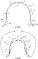
- FIG. 1 is a perspective view of a self-expanding device according to an embodiment of the invention shown in a relaxed condition;
- FIG. 2 is a side view of the device of FIG. 1 ;
- FIG. 3 is a section view through line A-A of FIG. 2 ;
- FIG. 4 is a top view of the device of FIGS. 1 to 3 illustrating the inversion direction
- FIG. 5 is a perspective view of the device of FIGS. 1 to 4 in a deployed configuration
- FIG. 6 is a front view of the device of FIGS. 1 to 5 in the deployed configuration
- FIG. 7 is an enlarged view of a segment of the body of the device of FIGS. 1 to 6 ;
- FIG. 8 is a section view through line B-B of FIG. 6 ;
- FIG. 9 is a top view of the device of FIGS. 1 to 8 in the deployed configuration
- FIG. 10 is an enlarged part-sectional view of the device of FIGS. 1 to 9 through a central one of the anchoring portions;
- FIG. 11 is an enlarged perspective view of the anchoring portions of the device of FIGS. 1 to 10 in the relaxed condition
- FIG. 12 is a perspective view of the device of FIGS. 1 to 11 shown in the loading configuration
- FIG. 13 is a schematic illustrating a first tracheal resection procedure using the device of FIGS. 1 to 12 in a loading configuration
- FIG. 14 is a schematic illustrating a second tracheal resection procedure using the device of FIGS. 1 to 12 in a loading configuration
- FIG. 15 is a perspective view of a self-expanding device according to another embodiment of the invention shown in a relaxed condition
- FIG. 16 is a perspective view of the device of FIG. 15 shown in a flexed condition.
- the body 2 and anchoring portions 3 are both formed integrally of a composite material including engineered cartilage and a biostable polymeric material. It is also envisaged that the body 2 may be formed solely of engineered cartilage or a biostable polymeric material.
- the axial edges 21 of the body 2 each include cartilage mapping undulations 22 which define a series of smooth projections or crests 23 which engage the cartilage rings of a trachea within which the stent 1 is to be received.
- the projections 23 are received between such rings to increase the grip and prevent the stent 1 moving once in place and deployed.
- each anchoring portion 3 When the stent 1 is in the relaxed condition, the central part 31 of the anchoring portion 3 has a positive curvature and the anchoring portions 3 converge towards each other, that is to say each anchoring portion 3 extends slightly inwardly (as well as axially) from the end 2 a , 2 b of the body 2 .
- the axial sides 32 of each anchoring portion 3 have a negative curvature, opposite the positive curvature of the central part 31 , that is to say the axial sides 32 have a reversed curvature relative to the central part 31 of the anchoring portion 3 .
- the central portion 5 with a negative curvature is invertible from a relaxed condition to a flexed condition. This is achieved by urging the edge portions 6 relative to the central portion 5 in the direction indicated by the arrows until the body 2 inverts, or folds back on itself, into a flexed condition in which the central portion 5 has positive curvature.
- the central portion 5 is invertible while the edge portions 6 remain in an un-inverted state.
- the first section 91 extends between retaining members 8 a , 8 b located outside of the stent 1 at each of its ends.
- the retaining members 8 a , 8 b are a pair of biodegradable stowing pins 8 a , 8 b connected orthogonal to the first section 91 .
- the stowing pins 8 a , 8 b are sufficiently wide as to not slip back through the retention holes 42 hence preventing the inadvertent deployment of the stent 1 .
- FIGS. 13 and 14 there is shown a schematic representation of each of two trachea resection procedures.
- a tube T is inserted into the trachea TR of a patient and air A is introduced into the tube T.
- An elongate opening O is formed in the trachea TR along a defective trachea section DTS with a flap F being formed for grippage of the lower section of the trachea TR.
- the tube T is then drawn through the opening O or a further tube T is inserted therethrough through which air is introduced for the resection procedure.
Landscapes
- Health & Medical Sciences (AREA)
- Engineering & Computer Science (AREA)
- Biomedical Technology (AREA)
- Heart & Thoracic Surgery (AREA)
- Life Sciences & Earth Sciences (AREA)
- Cardiology (AREA)
- Oral & Maxillofacial Surgery (AREA)
- Transplantation (AREA)
- Veterinary Medicine (AREA)
- Vascular Medicine (AREA)
- Public Health (AREA)
- Animal Behavior & Ethology (AREA)
- General Health & Medical Sciences (AREA)
- Optics & Photonics (AREA)
- Physics & Mathematics (AREA)
- Prostheses (AREA)
- Media Introduction/Drainage Providing Device (AREA)
Abstract
Description
Claims (20)
Applications Claiming Priority (4)
| Application Number | Priority Date | Filing Date | Title |
|---|---|---|---|
| GB1622215 | 2016-12-23 | ||
| GB1622215.0 | 2016-12-23 | ||
| GBGB1622215.0A GB201622215D0 (en) | 2016-12-23 | 2016-12-23 | Expanding device |
| PCT/GB2017/053852 WO2018115881A1 (en) | 2016-12-23 | 2017-12-21 | Expanding device |
Publications (2)
| Publication Number | Publication Date |
|---|---|
| US20190350731A1 US20190350731A1 (en) | 2019-11-21 |
| US11147697B2 true US11147697B2 (en) | 2021-10-19 |
Family
ID=58360564
Family Applications (1)
| Application Number | Title | Priority Date | Filing Date |
|---|---|---|---|
| US16/472,842 Active 2038-07-25 US11147697B2 (en) | 2016-12-23 | 2017-12-21 | Expanding device |
Country Status (4)
| Country | Link |
|---|---|
| US (1) | US11147697B2 (en) |
| EP (1) | EP3558173B1 (en) |
| GB (1) | GB201622215D0 (en) |
| WO (1) | WO2018115881A1 (en) |
Families Citing this family (2)
| Publication number | Priority date | Publication date | Assignee | Title |
|---|---|---|---|---|
| US11752020B2 (en) * | 2019-06-19 | 2023-09-12 | Michael J. Spearman | Tool for placement of degradable ostial stent |
| US11351024B2 (en) * | 2019-06-21 | 2022-06-07 | Lazzaro Medical, LLC | Airway support device |
Citations (30)
| Publication number | Priority date | Publication date | Assignee | Title |
|---|---|---|---|---|
| SU1635980A1 (en) | 1988-12-27 | 1991-03-23 | Всесоюзный научный центр хирургии АМН СССР | Device for esophagus stenosis endoprosthesis installation |
| FR2797176A1 (en) | 1999-08-06 | 2001-02-09 | Alain Fouere | Vascular endoprosthesis made in one piece from thin plate with curved section and lateral supports |
| US20010012961A1 (en) | 1999-02-16 | 2001-08-09 | Deem Mark E. | Apparatus and methods for selectively stenting a portion of a vessel wall |
| US20010053932A1 (en) | 1998-09-10 | 2001-12-20 | Percardia, Inc., | Designs for left ventricular conduit |
| US20020007222A1 (en) | 2000-04-11 | 2002-01-17 | Ashvin Desai | Method and apparatus for supporting a body organ |
| US20020042564A1 (en) | 1999-08-05 | 2002-04-11 | Cooper Joel D. | Devices for creating collateral channels in the lungs |
| US20020107540A1 (en) | 2001-01-23 | 2002-08-08 | Whalen Mark J. | Endourethral device & method |
| WO2003099165A1 (en) | 2002-05-23 | 2003-12-04 | Allium Inc. | Medical device having a tubular portion |
| US20050096498A1 (en) | 2001-04-24 | 2005-05-05 | Houser Russell A. | Sizing and shaping device for treating congestive heart failure |
| US20060037617A1 (en) | 2004-04-19 | 2006-02-23 | Walke Amrish J | Airway implant devices and methods of use |
| US20080039931A1 (en) | 2006-04-25 | 2008-02-14 | Surmodics, Inc. | Hydrophilic shape memory insertable medical articles |
| US20090005860A1 (en) | 2007-06-27 | 2009-01-01 | Gale David C | Method to fabricate a stent having selected morphology to reduce restenosis |
| US20090209972A1 (en) | 2008-02-20 | 2009-08-20 | Loushin Michael K H | Ventilation Device and Insertion System Therefor |
| US20090270971A1 (en) | 2008-04-24 | 2009-10-29 | Medtronic Vascular, Inc. | Prosthesis Fixation Apparatus and Methods |
| US20090326640A1 (en) | 2007-02-01 | 2009-12-31 | Shinichi Yoshimura | Medical device for body cavity and method of producing the same |
| US20100262156A1 (en) | 2009-04-09 | 2010-10-14 | Medtronic Vascular, Inc. | Endoventricular Stay and Delivery System |
| US20110022149A1 (en) | 2007-06-04 | 2011-01-27 | Cox Brian J | Methods and devices for treatment of vascular defects |
| US20110288625A1 (en) | 2008-10-30 | 2011-11-24 | Macquarie University | Vessel Support Device and Methods for Supporting a Vessel |
| US20120035715A1 (en) | 2010-08-09 | 2012-02-09 | Boston Scientific Scimed, Inc. | Tracheal Stent With Longitudinal Ribs to Minimize Stent Movement, Coughing and Halitosis |
| US8187315B1 (en) | 2006-12-08 | 2012-05-29 | Cardica, Inc. | Partial stent for treatment of a vascular aneurysm |
| US20140072610A1 (en) | 2011-03-21 | 2014-03-13 | National University Of Singapore | Bioabsorbable tracheal stent, and method of manufacturing thereof |
| US20140079758A1 (en) | 2012-09-19 | 2014-03-20 | Merit Medical Systems, Inc. | Electrospun material covered medical appliances and methods of manufacture |
| US20150148886A1 (en) | 2012-05-21 | 2015-05-28 | Medplate Lifesciences Corporation | Collapsible, shape memory alloy structures and folding fixtures for collapsing same |
| US20150223922A1 (en) | 2014-02-12 | 2015-08-13 | Boston Scientific Scimed Inc. | Lung elasticity restoring device and related methods of use and manufacture |
| US20150272750A1 (en) | 2012-10-02 | 2015-10-01 | Icon Medical Corp. | Expandable Device |
| US20150342765A1 (en) | 2014-05-30 | 2015-12-03 | Boston Scientific Scimed, Inc. | Endoluminal stents and methods of delivery |
| WO2016030898A1 (en) | 2014-08-27 | 2016-03-03 | Amnis Therapeutics Ltd. | Implantable devices comprising graft membranes |
| US20160128852A1 (en) | 2014-11-06 | 2016-05-12 | Boston Scientific Scimed, Inc. | Tracheal stent |
| US20160193029A1 (en) | 2013-05-23 | 2016-07-07 | Endospan Ltd. | Ascending aorta stent-graft system |
| US20160199085A1 (en) | 2013-04-13 | 2016-07-14 | Solinas Medical Inc. | Self-closing devices and apparatus and methods for making and delivering them |
-
2016
- 2016-12-23 GB GBGB1622215.0A patent/GB201622215D0/en not_active Ceased
-
2017
- 2017-12-21 US US16/472,842 patent/US11147697B2/en active Active
- 2017-12-21 EP EP17823191.6A patent/EP3558173B1/en active Active
- 2017-12-21 WO PCT/GB2017/053852 patent/WO2018115881A1/en unknown
Patent Citations (30)
| Publication number | Priority date | Publication date | Assignee | Title |
|---|---|---|---|---|
| SU1635980A1 (en) | 1988-12-27 | 1991-03-23 | Всесоюзный научный центр хирургии АМН СССР | Device for esophagus stenosis endoprosthesis installation |
| US20010053932A1 (en) | 1998-09-10 | 2001-12-20 | Percardia, Inc., | Designs for left ventricular conduit |
| US20010012961A1 (en) | 1999-02-16 | 2001-08-09 | Deem Mark E. | Apparatus and methods for selectively stenting a portion of a vessel wall |
| US20020042564A1 (en) | 1999-08-05 | 2002-04-11 | Cooper Joel D. | Devices for creating collateral channels in the lungs |
| FR2797176A1 (en) | 1999-08-06 | 2001-02-09 | Alain Fouere | Vascular endoprosthesis made in one piece from thin plate with curved section and lateral supports |
| US20020007222A1 (en) | 2000-04-11 | 2002-01-17 | Ashvin Desai | Method and apparatus for supporting a body organ |
| US20020107540A1 (en) | 2001-01-23 | 2002-08-08 | Whalen Mark J. | Endourethral device & method |
| US20050096498A1 (en) | 2001-04-24 | 2005-05-05 | Houser Russell A. | Sizing and shaping device for treating congestive heart failure |
| WO2003099165A1 (en) | 2002-05-23 | 2003-12-04 | Allium Inc. | Medical device having a tubular portion |
| US20060037617A1 (en) | 2004-04-19 | 2006-02-23 | Walke Amrish J | Airway implant devices and methods of use |
| US20080039931A1 (en) | 2006-04-25 | 2008-02-14 | Surmodics, Inc. | Hydrophilic shape memory insertable medical articles |
| US8187315B1 (en) | 2006-12-08 | 2012-05-29 | Cardica, Inc. | Partial stent for treatment of a vascular aneurysm |
| US20090326640A1 (en) | 2007-02-01 | 2009-12-31 | Shinichi Yoshimura | Medical device for body cavity and method of producing the same |
| US20110022149A1 (en) | 2007-06-04 | 2011-01-27 | Cox Brian J | Methods and devices for treatment of vascular defects |
| US20090005860A1 (en) | 2007-06-27 | 2009-01-01 | Gale David C | Method to fabricate a stent having selected morphology to reduce restenosis |
| US20090209972A1 (en) | 2008-02-20 | 2009-08-20 | Loushin Michael K H | Ventilation Device and Insertion System Therefor |
| US20090270971A1 (en) | 2008-04-24 | 2009-10-29 | Medtronic Vascular, Inc. | Prosthesis Fixation Apparatus and Methods |
| US20110288625A1 (en) | 2008-10-30 | 2011-11-24 | Macquarie University | Vessel Support Device and Methods for Supporting a Vessel |
| US20100262156A1 (en) | 2009-04-09 | 2010-10-14 | Medtronic Vascular, Inc. | Endoventricular Stay and Delivery System |
| US20120035715A1 (en) | 2010-08-09 | 2012-02-09 | Boston Scientific Scimed, Inc. | Tracheal Stent With Longitudinal Ribs to Minimize Stent Movement, Coughing and Halitosis |
| US20140072610A1 (en) | 2011-03-21 | 2014-03-13 | National University Of Singapore | Bioabsorbable tracheal stent, and method of manufacturing thereof |
| US20150148886A1 (en) | 2012-05-21 | 2015-05-28 | Medplate Lifesciences Corporation | Collapsible, shape memory alloy structures and folding fixtures for collapsing same |
| US20140079758A1 (en) | 2012-09-19 | 2014-03-20 | Merit Medical Systems, Inc. | Electrospun material covered medical appliances and methods of manufacture |
| US20150272750A1 (en) | 2012-10-02 | 2015-10-01 | Icon Medical Corp. | Expandable Device |
| US20160199085A1 (en) | 2013-04-13 | 2016-07-14 | Solinas Medical Inc. | Self-closing devices and apparatus and methods for making and delivering them |
| US20160193029A1 (en) | 2013-05-23 | 2016-07-07 | Endospan Ltd. | Ascending aorta stent-graft system |
| US20150223922A1 (en) | 2014-02-12 | 2015-08-13 | Boston Scientific Scimed Inc. | Lung elasticity restoring device and related methods of use and manufacture |
| US20150342765A1 (en) | 2014-05-30 | 2015-12-03 | Boston Scientific Scimed, Inc. | Endoluminal stents and methods of delivery |
| WO2016030898A1 (en) | 2014-08-27 | 2016-03-03 | Amnis Therapeutics Ltd. | Implantable devices comprising graft membranes |
| US20160128852A1 (en) | 2014-11-06 | 2016-05-12 | Boston Scientific Scimed, Inc. | Tracheal stent |
Non-Patent Citations (1)
| Title |
|---|
| International Search Report and Written Opinion dated Mar. 7, 2018 in connection with corresponding International Application No. PCT/US2017/053852. |
Also Published As
| Publication number | Publication date |
|---|---|
| EP3558173B1 (en) | 2022-11-16 |
| WO2018115881A1 (en) | 2018-06-28 |
| GB201622215D0 (en) | 2017-02-08 |
| EP3558173A1 (en) | 2019-10-30 |
| US20190350731A1 (en) | 2019-11-21 |
Similar Documents
| Publication | Publication Date | Title |
|---|---|---|
| TWI781131B (en) | Device for fixation in a body lumen | |
| US20210068996A1 (en) | Lattice | |
| ES2946944T3 (en) | Directional expansion of intraluminal devices | |
| AU2015210440B2 (en) | Stent | |
| JP4566988B2 (en) | Separable and recoverable stent assembly | |
| EP3646818B1 (en) | Improved surgical implant devices | |
| JP6431183B2 (en) | In-vivo prosthesis delivery system with improved storage | |
| US20240216155A1 (en) | Hydration delivery system for stents | |
| JP6530400B2 (en) | Tapered implantable device and method of making such device | |
| EP2528540A1 (en) | Biodegradable protrusions on inflatable device | |
| US9572696B2 (en) | Stent loading and delivery device having a loading basket lock mechanism | |
| US8790388B2 (en) | Stent with reduced profile | |
| AU2015280419A1 (en) | Thin-film composite retrievable endovascular devices and method of use | |
| US11147697B2 (en) | Expanding device | |
| US10575972B2 (en) | Medical device with induction triggered anchors and system for deployment of the same | |
| AU2017203267B2 (en) | Endoprosthesis |
Legal Events
| Date | Code | Title | Description |
|---|---|---|---|
| AS | Assignment |
Owner name: TONKIN LIU STENTS LIMITED, UNITED KINGDOM Free format text: ASSIGNMENT OF ASSIGNORS INTEREST;ASSIGNORS:LIU, ANNA;TONKIN, MICHAEL;REEL/FRAME:049556/0819 Effective date: 20190618 |
|
| FEPP | Fee payment procedure |
Free format text: ENTITY STATUS SET TO UNDISCOUNTED (ORIGINAL EVENT CODE: BIG.); ENTITY STATUS OF PATENT OWNER: SMALL ENTITY |
|
| FEPP | Fee payment procedure |
Free format text: ENTITY STATUS SET TO SMALL (ORIGINAL EVENT CODE: SMAL); ENTITY STATUS OF PATENT OWNER: SMALL ENTITY |
|
| STPP | Information on status: patent application and granting procedure in general |
Free format text: DOCKETED NEW CASE - READY FOR EXAMINATION |
|
| STPP | Information on status: patent application and granting procedure in general |
Free format text: NON FINAL ACTION MAILED |
|
| STPP | Information on status: patent application and granting procedure in general |
Free format text: RESPONSE TO NON-FINAL OFFICE ACTION ENTERED AND FORWARDED TO EXAMINER |
|
| STPP | Information on status: patent application and granting procedure in general |
Free format text: NOTICE OF ALLOWANCE MAILED -- APPLICATION RECEIVED IN OFFICE OF PUBLICATIONS |
|
| STPP | Information on status: patent application and granting procedure in general |
Free format text: PUBLICATIONS -- ISSUE FEE PAYMENT RECEIVED |
|
| STPP | Information on status: patent application and granting procedure in general |
Free format text: PUBLICATIONS -- ISSUE FEE PAYMENT VERIFIED |
|
| STCF | Information on status: patent grant |
Free format text: PATENTED CASE |