US11142267B2 - Passive walking apparatus and passive walking module - Google Patents
Passive walking apparatus and passive walking module Download PDFInfo
- Publication number
- US11142267B2 US11142267B2 US15/779,667 US201715779667A US11142267B2 US 11142267 B2 US11142267 B2 US 11142267B2 US 201715779667 A US201715779667 A US 201715779667A US 11142267 B2 US11142267 B2 US 11142267B2
- Authority
- US
- United States
- Prior art keywords
- leg
- crank
- coupled
- connection
- passive walking
- Prior art date
- Legal status (The legal status is an assumption and is not a legal conclusion. Google has not performed a legal analysis and makes no representation as to the accuracy of the status listed.)
- Active, expires
Links
Images


Classifications
-
- B—PERFORMING OPERATIONS; TRANSPORTING
- B62—LAND VEHICLES FOR TRAVELLING OTHERWISE THAN ON RAILS
- B62D—MOTOR VEHICLES; TRAILERS
- B62D57/00—Vehicles characterised by having other propulsion or other ground- engaging means than wheels or endless track, alone or in addition to wheels or endless track
- B62D57/02—Vehicles characterised by having other propulsion or other ground- engaging means than wheels or endless track, alone or in addition to wheels or endless track with ground-engaging propulsion means, e.g. walking members
- B62D57/032—Vehicles characterised by having other propulsion or other ground- engaging means than wheels or endless track, alone or in addition to wheels or endless track with ground-engaging propulsion means, e.g. walking members with alternately or sequentially lifted supporting base and legs; with alternately or sequentially lifted feet or skid
-
- F—MECHANICAL ENGINEERING; LIGHTING; HEATING; WEAPONS; BLASTING
- F16—ENGINEERING ELEMENTS AND UNITS; GENERAL MEASURES FOR PRODUCING AND MAINTAINING EFFECTIVE FUNCTIONING OF MACHINES OR INSTALLATIONS; THERMAL INSULATION IN GENERAL
- F16H—GEARING
- F16H21/00—Gearings comprising primarily only links or levers, with or without slides
- F16H21/10—Gearings comprising primarily only links or levers, with or without slides all movement being in, or parallel to, a single plane
- F16H21/40—Gearings comprising primarily only links or levers, with or without slides all movement being in, or parallel to, a single plane for interconverting rotary motion and oscillating motion
Definitions
- the present invention relates to a passive walking apparatus and a passive walking module.
- a passive walking apparatus described in Japanese Patent Laying-Open No. 2011-131677 represents a conventional passive walking apparatus.
- the passive walking apparatus described in PTD 1 includes two legs and a hip joint portion including a hip shaft. These two legs are attached to the hip joint portion by being pivotably coupled to the hip shaft.
- PTD 1 Japanese Patent Laying-Open No. 2011-131677
- the passive walking apparatus described in PTD 1 does not include a mechanism for having two legs operate in coordination. Therefore, it is difficult for the passive walking apparatus described in PTD 1 to continue walking in a stable manner.
- the present invention was made in view of such a problem of the conventional art.
- the present invention more specifically provides a passive walking apparatus capable of continuing passive walking in a stable manner.
- a passive walking apparatus includes a hip portion including a first side portion and a second side portion located opposite to the first side portion, a first leg coupled to the first side portion, a second leg coupled to the second side portion, and a crank mechanism including a first-leg-side crank portion provided on a side of the first side portion, a second-leg-side crank portion provided on a side of the second side portion as being opposite in phase to the first-leg-side crank portion, a crankshaft coupling the first-leg-side crank portion and the second-leg-side crank portion to each other, a first-leg-side connection portion connected to the first leg and the first-leg-side crank portion, and a second-leg-side connection portion connected to the second-leg-side crank portion and the second leg.
- the first-leg-side connection portion When the first leg moves rearward from the front relatively to the hip portion as being in contact with a walking surface, the first-leg-side connection portion has the first-leg-side crank portion pivot and the first-leg-side crank portion has the second-leg-side crank portion pivot around the crankshaft.
- the second-leg-side crank portion moves the second leg forward from the rear relatively to the hip portion with the second-leg-side connection portion being interposed.
- the passive walking apparatus can continue stable passive walking.
- FIG. 1 is a side view of a passive walking apparatus according to a first embodiment.
- FIG. 2 is a side view of the passive walking apparatus according to the first embodiment at a time point of contact of a support leg with a walking surface.
- FIG. 3 is a side view of the passive walking apparatus according to the first embodiment at a time point of passage of the support leg in the vicinity of a portion directly under a hip portion.
- FIG. 4 is a side view of the passive walking apparatus according to the first embodiment at a time point of contact of an idling leg with the walking surface.
- FIG. 5 is a side view of a passive walking apparatus according to a first modification of the first embodiment.
- FIG. 6 is a side view of a passive walking apparatus according to a second modification of the first embodiment.
- FIG. 7A is a side view of a passive walking apparatus according to a second embodiment showing a construction on a side of a first leg.
- FIG. 7B is a side view of the passive walking apparatus according to the second embodiment showing only a construction on a side of a second leg.
- FIG. 8 is a schematic diagram for illustrating an operation on the side of the first leg of the passive walking apparatus according to the second embodiment at a time point immediately before contact of the first leg with the walking surface.
- FIG. 9 is a schematic diagram for illustrating an operation on the side of the second leg of the passive walking apparatus according to the second embodiment at the time point immediately before contact of the first leg with the walking surface.
- FIG. 10 is a schematic diagram for illustrating an operation on the side of the first leg of the passive walking apparatus according to the second embodiment at a time point immediately after contact of the first leg with the walking surface.
- FIG. 11 is a schematic diagram for illustrating an operation on the side of the second leg of the passive walking apparatus according to the second embodiment at the time point immediately after contact of the first leg with the walking surface.
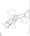
- FIG. 12 is a side view of a passive walking apparatus according to a third embodiment.
- FIG. 13 is a side view of the passive walking apparatus according to the third embodiment showing only a construction on the side of the second leg.
- FIG. 14 is a side view of a passive walking apparatus according to a fourth embodiment showing only a construction on the side of the first leg.
- FIG. 15 is a side view of the passive walking apparatus according to the fourth embodiment showing only a construction on the side of the second leg.
- FIG. 16 is a side view showing only a construction on the side of the first leg of the passive walking apparatus according to the fourth embodiment when the first leg starts to come in contact with the walking surface.
- FIG. 17 is a side view showing only a construction on the side of the first leg of the passive walking apparatus according to the fourth embodiment when the first leg moves away from the walking surface.
- FIG. 18 is a side view showing only a construction on the side of the first leg of the passive walking apparatus according to the fourth embodiment when the first leg comes in contact with the walking surface.
- FIG. 19 is a perspective view of a passive walking apparatus according to a fifth embodiment.
- FIG. 20 is a plan view of the passive walking apparatus according to the fifth embodiment.
- FIG. 21 is a plan view of the passive walking apparatus according to the fifth embodiment when the first leg is located in front during walking.
- FIG. 22 is a plan view of the passive walking apparatus according to the fifth embodiment when the second leg is located in front during walking.
- FIG. 23 is a side view of a passive walking apparatus according to a sixth embodiment.
- FIG. 1 is a side view of passive walking apparatus 100 according to the first embodiment.
- passive walking apparatus 100 according to the first embodiment includes a hip portion 1 .
- Hip portion 1 includes a first side portion 11 and a second side portion 12 (not shown).
- Second side portion 12 is a side portion of hip portion 1 located opposite to first side portion 11 .
- Passive walking apparatus 100 includes a leg portion 2 .
- the number of legs included in leg portion 2 is set, for example, to two.
- the number of legs included in leg portion 2 is not limited as such.
- the number of legs included in leg portion 2 may be set to three or more.
- first leg 21 is coupled to first side portion 11 .
- First leg 21 is pivotable with respect to first side portion 11 . More specifically, first leg 21 is movable forward and rearward around a point of coupling to hip portion 1 .
- Forward herein means a direction of movement of passive walking apparatus 100 according to the first embodiment and rearward means a direction opposite to the direction of movement of passive walking apparatus 100 according to the first embodiment.
- First leg 21 includes a thigh portion 21 a , a lower leg portion 21 b , and a foot portion 21 c .
- Foot portion 21 c is a portion in contact with a walking surface GR.
- Lower leg portion 21 b is coupled to foot portion 21 c .
- Thigh portion 21 a is coupled to lower leg portion 21 b with a first connection member 32 a which will be described later being interposed.
- First leg 21 may further include a calf portion 21 d .
- Calf portion 21 d has one end coupled to foot portion 21 c.
- Second leg 22 is similar in construction to first leg 21 .
- Second leg 22 is coupled to second side portion 12 as being movable forward and rearward around a point of coupling to hip portion 1 and includes a thigh portion 22 a , a lower leg portion 22 b , and a foot portion 22 c.
- Passive walking apparatus 100 includes a crank mechanism 3 .
- Crank mechanism 3 includes a crank portion 31 , a connection portion 32 , a crankshaft 33 , a crank portion 34 , and a connection portion 35 .
- Crank portion 31 is provided in first side portion 11 of hip portion 1 .
- Connection portion 32 is connected to crank portion 31 and first leg 21 .
- Crank portion 34 is provided in second side portion 12 of hip portion 1 .
- Connection portion 35 is connected to crank portion 34 and second leg 22 .
- Crankshaft 33 is coupled to crank portion 31 and crank portion 34 .
- Crank portion 34 is provided as being opposite in phase to crank portion 31 .
- Crank portion 34 is provided as being in point symmetry to crank portion 31 with respect to crankshaft 33 .
- Connection portion 32 has crank portion 31 pivot when first leg 21 moves rearward from the front relatively to hip portion 1 as being in contact with walking surface GR when first leg 21 functions as a support leg (a leg on a side in contact with walking surface GR). Crank portion 31 transmits this pivot to crank portion 34 with crankshaft 33 being interposed. With this pivot, crank portion 34 moves second leg 22 functioning as an idling leg (a leg on a side not in contact with walking surface GR) forward from the rear relatively to hip portion 1 with connection portion 35 being interposed.
- connection portion 35 has crank portion 34 pivot when second leg 22 moves rearward from the front relatively to hip portion 1 .
- Crank portion 34 transmits this pivot to crank portion 31 with crankshaft 33 being interposed.
- crank portion 31 moves first leg 21 functioning as the idling leg forward from the rear relatively to hip portion 1 with connection portion 32 being interposed.
- crank portion 31 includes a first crank 31 a and a second crank 31 b .
- Connection portion 32 includes a first connection member 32 a and a second connection member 32 b.
- First connection member 32 a has one end coupled to first crank 31 a .
- First connection member 32 a is coupled also to first leg 21 .
- First connection member 32 a is preferably coupled to thigh portion 21 a .
- First connection member 32 a is preferably coupled to first crank 31 a and first leg 21 such that a straight line connecting a position of contact of first leg 21 with walking surface GR at a time point of the contact of first leg 21 with the walking surface to a point of connection of first crank 31 a to first connection member 32 a substantially matches with a tangent line of pivot of first crank 31 a (a tangent line of a circular path of pivot of first crank 31 a ).
- a case that the straight line connecting the position of contact of first leg 21 with walking surface GR at the time point of the contact of first leg 21 with the walking surface to the point of connection of first crank 31 a to first connection member 32 a substantially matches with the tangent line of pivot of first crank 31 a includes not only a case that the straight line connecting the position of contact of first leg 21 with walking surface GR at the time point of the contact of first leg 21 with the walking surface to the point of connection of first crank 31 a to first connection member 32 a matches with the tangent line of pivot of first crank 31 a but also a case that an angle formed between the straight line connecting the position of contact of first leg 21 with walking surface GR at the time point of the contact of first leg 21 with the walking surface to the point of connection of first crank 31 a to first connection member 32 a and the tangent line of pivot of first crank 31 a is within a range of ⁇ 10°.
- Second connection member 32 b has one end coupled to second crank 31 b .
- Second connection member 32 b is coupled also to first leg 21 .
- Second connection member 32 b is preferably coupled to lower leg portion 21 b .
- Second connection member 32 b may be coupled to the other end of calf portion 21 d .
- Second connection member 32 b may be constituted of a plurality of members.
- Second connection member 32 b is preferably coupled to second crank 31 b such that a straight line connecting a position of contact of first leg 21 at a time point of passage of first leg 21 under hip portion 1 to a point of connection of second crank 31 b to second connection member 32 b substantially matches with a tangent line of pivot of second crank 31 b.
- a case that the straight line connecting the position of contact of first leg 21 at the time point of passage of first leg 21 under hip portion 1 to the point of connection of second crank 31 b to second connection member 32 b substantially matches with the tangent line of pivot of second crank 31 b includes not only a case that the straight line connecting the position of contact of first leg 21 at the time point of passage of first leg 21 under hip portion 1 to the point of connection of second crank 31 b to second connection member 32 b matches with the tangent line of pivot of second crank 31 b but also a case that an angle formed between the straight line connecting the position of contact of first leg 21 at the time point of passage of first leg 21 under hip portion 1 to the point of connection of second crank 31 b to second connection member 32 b and the tangent line of pivot of second crank 31 b is within a range of ⁇ 10°.
- a direction of extension of an arm of first crank 31 a and a direction of extension of an arm of second crank 31 b form a prescribed angle. From a different point of view, first crank 31 a and second crank 31 b are arranged such that their positions of dead points are not superimposed on each other. An angle formed between the direction of extension of the arm of first crank 31 a and the direction of extension of the arm of second crank 31 b is set, for example, to 90°.
- Crank portion 34 is similar in construction to crank portion 31 .
- Crank portion 34 includes a first crank 34 a and a second crank 34 b , and first crank 34 a and second crank 34 b are arranged such that their positions of dead points are not superimposed on each other.
- First crank 34 a is opposite in phase to first crank 31 a and second crank 34 b is opposite in phase to second crank 31 b.
- Connection portion 35 is also similar in construction to connection portion 32 .
- Connection portion 35 includes a first connection member 35 a and a second connection member 35 b .
- First connection member 35 a has one end coupled to first crank 34 a .
- First connection member 35 a is coupled also to second leg 22 .
- First connection member 35 a is preferably coupled to thigh portion 22 a.
- Second connection member 35 b has one end coupled to second crank 34 b . Second connection member 35 b is coupled also to second leg 22 . Second connection member 35 b is preferably coupled to lower leg portion 22 b . Second connection member 35 b may be coupled to the other end of calf portion 22 d.
- FIG. 2 is a side view of passive walking apparatus 100 according to the first embodiment at a time point of contact of the support leg with walking surface GR.
- first leg 21 functioning as the support leg comes in contact with walking surface GR and thereafter moves rearward from the front relatively to hip portion 1 with a point of coupling between first leg 21 and hip portion 1 being defined as an axis.
- thigh portion 21 a moves rearward from the front relatively to hip portion 1 with the point of coupling between first leg 21 and hip portion 1 being defined as the axis (see an arrow A 1 in the figure).
- This movement of thigh portion 21 a is transmitted to first connection member 32 a so that first connection member 32 a has first crank 31 a pivot (see an arrow A 2 in the figure). Consequently, this pivot is transmitted also to crank portion 34 with crankshaft 33 being interposed, and connection portion 35 moves second leg 22 functioning as the idling leg forward from the rear relatively to hip portion 1 .
- FIG. 3 is a side view of passive walking apparatus 100 according to the first embodiment at a time point of passage of the support leg in the vicinity of a portion directly under hip portion 1 .
- an angle formed between the direction of extension of first connection member 32 a and the direction of extension of the arm of first crank 31 a has become small (that is, first crank 31 a is close to the dead point). Therefore, it is difficult for first connection member 32 a to have first crank 31 a pivot in this state.
- second connection member 32 b is able to have second crank 31 b pivot (see an arrow A 3 in the figure).
- FIG. 4 is a side view of passive walking apparatus 100 according to the first embodiment at a time point of contact of the idling leg with walking surface GR.
- first leg 21 when the support leg (first leg 21 ) moves further rearward when viewed from hip portion 1 , an angle formed between the direction of extension of second connection member 32 b and the direction of extension of the arm of second crank 31 b also becomes smaller. Therefore, it becomes difficult for second connection member 32 b to have second crank 31 b pivot.
- crank portion 31 and crank portion 34 continues.
- first crank 31 a first crank 34 a
- second crank 31 b second crank 34 b
- first connection member 35 a coupled to second leg 22 functioning as the idling leg starts to have first crank 34 a pivot before second connection member 32 a is unable to have second crank 31 b pivot so that passive walking continues.
- passive walking apparatus 100 As set forth above, in passive walking apparatus 100 according to the first embodiment, movement of the support leg (for example, first leg 21 ) rearward from the front relatively to hip portion 1 is converted to movement of the idling leg (for example, second leg 22 ) forward from the rear relatively to hip portion 1 , with the connection portion (for example, connection member 32 ) on the side of the support leg, the crank portion (for example, crank portion 31 ) on the side of the support leg, crankshaft 33 , the crank portion (for example, crank portion 34 ) on the side of the idling leg (for example, second leg 22 ), and the connection portion (for example, connection portion 35 ) on the side of the idling leg being interposed. Therefore, passive walking apparatus 100 according to the first embodiment can continue stable passive walking.
- connection portion for example, connection member 32
- crank portion for example, crank portion 31
- the crank portion on the side of the support leg includes the first crank (for example, first crank 31 a ) and the second crank different in position of the dead point from the first crank (for example, second crank 31 b ) and the connection portion (for example, connection portion 32 ) on the side of the support leg has at least any one of the first crank and the second crank pivot throughout a period during which the support leg moves rearward from the front relatively to hip portion 1 , more stable passive walking can continue.
- the connection portion (for example, connection portion 32 ) includes the first connection member (for example, first connection member 32 a ) and the second connection member (for example, second connection member 32 b ), the first connection member is connected to the thigh portion, and the second connection member is connected to the lower leg portion, force received by the support leg from walking surface GR can more efficiently be converted to pivot of the first crank and the second crank. Therefore, in this case, more stable passive walking can continue.
- a construction of a passive walking apparatus 110 according to a modification of the first embodiment will be described below. A difference from the first embodiment will mainly be described and redundant description will not be repeated.
- FIG. 5 is a side view of passive walking apparatus 110 according to the first modification of the first embodiment.
- passive walking apparatus 110 according to the first modification of the first embodiment includes hip portion 1 , leg portion 2 , and crank mechanism 3 similarly to passive walking apparatus 100 according to the first embodiment.
- Passive walking apparatus 110 according to the first modification of the first embodiment is different from passive walking apparatus 100 according to the first embodiment in construction of leg portion 2 and crank mechanism 3 . More specifically, in passive walking apparatus 110 according to the first modification of the first embodiment, thigh portion 21 a (thigh portion 22 a ) is directly coupled to lower leg portion 21 b (lower leg portion 22 b ). First connection member 32 a (first connection member 35 a ) is coupled to a portion of coupling between thigh portion 21 a (thigh portion 22 a ) and lower leg portion 21 b (lower leg portion 22 b ).
- an angle formed between the direction of extension of the arm of first crank 31 a (first crank 34 a ) and the direction of extension of the arm of second crank 31 b (second crank 34 b ) is smaller than 90°
- second connection member 32 b (second connection member 35 b ) is connected to second crank 31 b (second crank 34 b ) and thigh portion 21 a (thigh portion 22 a ).
- calf portion 21 d (calf portion 22 d ) is coupled to first connection member 32 a (first connection member 35 a ).
- FIG. 6 is a side view of a passive walking apparatus 120 according to a second modification of the first embodiment.
- passive walking apparatus 120 according to the second modification of the first embodiment includes hip portion 1 , leg portion 2 , and crank mechanism 3 similarly to passive walking apparatus 100 according to the first embodiment and passive walking apparatus 110 according to the first modification of the first embodiment.
- Passive walking apparatus 120 according to the second modification of the first embodiment is different from passive walking apparatus 100 according to the first embodiment and passive walking apparatus 110 according to the first modification of the first embodiment in position where leg portion 2 and crank mechanism 3 are provided. More specifically, in passive walking apparatus 120 according to the second modification of the first embodiment, first leg 21 (second leg 22 ) is arranged in the rear of crank portion 31 (crank portion 34 ).
- a construction of a passive walking apparatus 200 according to a second embodiment will be described below. A difference from the first embodiment will mainly be described and redundant description will not be repeated.
- FIG. 7A is a side view of passive walking apparatus 200 according to the second embodiment which shows a construction on the side of first leg 21 .
- FIG. 7B is a side view of passive walking apparatus 200 according to the second embodiment showing only a construction on the side of second leg 22 .
- passive walking apparatus 200 according to the second embodiment includes hip portion 1 including first side portion 11 and second side portion 12 , leg portion 2 including first leg 21 coupled to first side portion 11 and second leg 22 coupled to second side portion 12 , and crank mechanism 3 .
- a protruding portion 13 is provided in first side portion 11 and a protruding portion 14 is provided in second side portion 12 .
- Protruding portion 13 and protruding portion 14 are preferably provided in the rear of and above a position where crank mechanism 3 is provided.
- Crank mechanism 3 of passive walking apparatus 200 includes crank portion 31 provided on the side of first side portion 11 , connection portion 32 connecting crank portion 31 and first leg 21 to each other, crankshaft 33 coupling crank portion 31 and crank portion 34 to each other, crank portion 34 , and connection portion 35 connecting crank portion 34 and second leg 22 to each other.
- Crank portion 31 is implemented by crank 31 c
- Connection portion 32 is implemented by a connection member 32 c .
- Connection member 32 c connects crank 31 c and first leg 21 to each other.
- Connection member 32 c includes a first portion 32 ca which is a portion extending toward first leg 21 and a second portion 32 cb which is a portion extending in a direction different from first portion 32 ca.
- Crank portion 34 is implemented by crank 34 c .
- Connection portion 35 is implemented by a connection member 35 c .
- Connection member 35 c connects crank 34 c and second leg 22 to each other.
- Connection member 35 c includes a first portion 35 ca which is a portion extending toward second leg 22 and a second portion 35 cb which is a portion extending in a direction toward a pivot assistance portion 4 .
- Passive walking apparatus 200 further includes pivot assistance portion 4 .
- Pivot assistance portion 4 is provided on each of the side of first side portion 11 and the side of second side portion 12 .
- Two pivot assistance portions 4 are coupled to second portion 32 cb of connection portion 32 c and second portion 35 cb of connection member 35 c , respectively.
- Pivot assistance portions 4 are thus coupled to crank 31 c and crank 34 c , respectively.
- Pivot assistance portion 4 is provided with a groove 41 .
- Pivot assistance portions 4 are coupled to first side portion 11 and second side portion 12 by inserting protruding portion 13 and protruding portion 14 into grooves 41 , respectively. Owing to sliding of protruding portion 13 and protruding portion 14 with respect to grooves 41 , positions of pivot assistance portions 4 are variable and pivot assistance portions 4 are pivotable around protruding portion 13 and protruding portion 14 , respectively.
- Pivot assistance portion 4 includes an elastic member 42 .
- Elastic member 42 is implemented, for example, by a coil spring.
- Elastic members 42 are provided in respective portions where pivot assistance portions 4 are coupled to connection member 32 c and connection member 35 c .
- Elastic members 42 have one ends attached to pivot assistance portions 4 and the other ends attached to connection member 32 c and connection member 35 c , respectively.
- elastic members 42 contract with movement of connection member 32 c and connection member 35 c in transition of leg portion 2 on the side as the support leg to the idling leg and extend with movement of connection member 32 c and connection member 35 c in movement of leg portion 2 on the side as the idling leg forward from the rear relatively to hip portion 1 .
- FIG. 8 is a schematic diagram for illustrating an operation on the side of first leg 21 of passive walking apparatus 200 according to the second embodiment at a time point immediately before contact of first leg 21 with the walking surface.
- FIG. 9 is a schematic diagram for illustrating an operation on the side of second leg 22 of passive walking apparatus 200 according to the second embodiment at the time point immediately before contact of first leg 21 with the walking surface.
- FIG. 10 is a schematic diagram for illustrating an operation on the side of first leg 21 of passive walking apparatus 200 according to the second embodiment at a time point immediately after contact of first leg 21 with the walking surface.
- FIG. 11 is a schematic diagram for illustrating an operation on the side of second leg 22 of passive walking apparatus 200 according to the second embodiment at a time point immediately after contact of second leg 22 with the walking surface.
- connection member 35 c can have crank 34 c pivot with reaction force from the ground transmitted from second leg 22 .
- pivot of crank 34 c is transmitted to crank 31 c with crankshaft 33 being interposed and connection member 32 c moves first leg 21 rearward from the front relatively to hip portion 1 .
- crank 31 c and crank 34 c pivot with reaction force from the ground transmitted from first leg 21 .
- passive walking apparatus 200 An effect of passive walking apparatus 200 according to the second embodiment will be described below.
- elastic member 42 of pivot assistance portion 4 biases connection member 35 c , for example, by contracting when second leg 22 moves away from the walking surface and extending when second leg 22 moves forward from the rear relatively to hip portion 1 . Consequently, pivot of crank 31 c and crank 34 c can be assisted.
- FIG. 12 is a side view of passive walking apparatus 400 according to the third embodiment.
- FIG. 13 is a side view of passive walking apparatus 400 according to the third embodiment showing only a construction on the side of second leg 22 .
- passive walking apparatus 400 includes hip portion 1 including first side portion 11 and second side portion 12 , leg portion 2 including first leg 21 coupled to first side portion 11 and second leg 22 coupled to second side portion 12 , and crank mechanism 3 .
- Crank mechanism 3 includes crank portion 31 , connection portion 32 , crankshaft 33 , crank portion 34 , connection portion 35 , a third crank 36 , a third crank 37 , a crankshaft 38 , and a synchronization mechanism 39 .
- First leg 21 includes thigh portion 21 a , lower leg portion 21 b , and foot portion 21 c .
- Second leg 22 includes thigh portion 22 a , lower leg portion 22 b , and foot portion 22 c .
- Third crank 36 and third crank 37 are coupled to each other with crankshaft 38 being interposed.
- Third crank 36 is located on the side of first side portion 11 .
- Third crank 37 is located on the side of second side portion 12 .
- Thigh portion 21 a is coupled to third crank 36 .
- Thigh portion 22 a is connected to third crank 37 .
- Third crank 36 is provided as being opposite in phase to third crank 37 .
- thigh portion 21 a is connected to third crank 36 such that a position of a point of connection to third crank 36 when first leg 21 is away from walking surface GR is farther from walking surface GR than a position of a point of connection to third crank 36 when first leg 21 is in contact with walking surface GR.
- thigh portion 22 a is connected to third crank 37 such that a position of a point of connection to third crank 37 when second leg 22 is away from walking surface GR is farther from walking surface GR than a position of a point of connection to third crank 37 when second leg 22 is in contact with walking surface GR.
- synchronization mechanism 39 includes a gear 39 a , a gear 39 b , and a gear 39 c arranged on the side of first side portion 11 and a gear 39 d , a gear 39 e , and a gear 39 f arranged on the side of second side portion 12 .
- Gear 39 a and gear 39 d are attached to crankshaft 33 .
- Gear 39 b and gear 39 e are attached to crankshaft 38 .
- Gear 39 c is arranged between gear 39 a and gear 39 b and meshed with gear 39 a and gear 39 b .
- Gear 39 f is arranged between gear 39 d and gear 39 e and meshed with gear 39 d and gear 39 e .
- a set of gear 39 a and gear 39 d , a set of gear 39 b and gear 39 e , and a set of gear 39 c and gear 39 f may each be implemented as a single gear.
- synchronization mechanism 39 is not limited as such.
- rotation of crankshaft 33 may be transmitted to third crank 36 and third crank 37 coupled to crankshaft 38 by coupling gear 39 a (gear 39 d ) and gear 39 b (gear 39 e ) to each other with a chain or a belt without providing gear 39 c and gear 39 f.
- connection portion 35 has crank portion 34 and crankshaft 33 pivot and rotate with reaction force from the ground transmitted from second leg 22 .
- crankshaft 38 rotates in synchronization with crankshaft 33 in the direction the same as crankshaft 33 . Consequently, when first leg 21 moves forward from the rear relatively to hip portion 1 , third crank 36 lifts first leg 21 away from walking surface GR.
- passive walking apparatus 400 according to the third embodiment walking with the idling leg being lifted higher than in passive walking apparatus 100 according to the first embodiment can be achieved.
- a construction of a passive walking apparatus 500 according to a fourth embodiment will be described below. A difference from the first embodiment will mainly be described and redundant description will not be repeated.
- FIG. 14 is a side view of passive walking apparatus 500 according to the fourth embodiment showing only a construction on the side of first leg 21 .
- FIG. 15 is a side view of passive walking apparatus 500 according to the fourth embodiment showing only a construction on the side of second leg 22 .
- passive walking apparatus 500 according to the fourth embodiment includes hip portion 1 including first side portion 11 and second side portion 12 , leg portion 2 including first leg 21 coupled to first side portion 11 and second leg 22 coupled to second side portion 12 , and crank mechanism 3 .
- Crank mechanism 3 includes crank portion 31 , connection portion 32 , crankshaft 33 , crank portion 34 , and connection portion 35 .
- First leg 21 includes thigh portion 21 a and lower leg portion 21 b .
- Second leg 22 includes thigh portion 22 a and lower leg portion 22 b .
- Lower leg portion 21 b includes a first end 21 ba and a second end 21 bb .
- First end 21 ba is an end of lower leg portion 21 b on a side of walking surface GR.
- Second end 21 bb is an end opposite to first end 21 ba .
- Lower leg portion 21 b is pivotably coupled to thigh portion 21 a at a point between first end 21 ba and second end 21 bb .
- Lower leg portion 21 b is preferably bent toward a third connection member 32 d at a point of coupling to thigh portion 21 a.
- Lower leg portion 22 b includes a first end 22 ba and a second end 22 bb .
- First end 22 ba is an end of lower leg portion 22 b on the side of walking surface GR.
- Second end 22 bb is an end opposite to first end 22 ba .
- Lower leg portion 22 b is pivotably coupled to thigh portion 22 a at a point between first end 22 ba and second end 22 bb .
- Lower leg portion 22 b is preferably bent toward a third connection portion 35 d at a point of coupling to thigh portion 22 a.
- Crank portion 31 is implemented by a crank 31 d .
- Connection portion 32 includes third connection member 32 d and a fourth connection member 32 e .
- Third connection member 32 d is connected to crank 31 d .
- Fourth connection member 32 e has one end pivotably coupled to lower leg portion 21 b on the side of second end 21 bb .
- Fourth connection member 32 e has the other end coupled to third connection member 32 d.
- Crank portion 34 is implemented by a crank 34 d .
- Connection portion 35 includes third connection member 35 d and a fourth connection member 35 e .
- Third connection member 35 d is connected to crank 34 d .
- Fourth connection member 35 e has one end pivotably coupled to lower leg portion 22 b on the side of second end 22 bb .
- Fourth connection member 35 e has the other end coupled to third connection member 35 d.
- FIG. 16 is a side view showing only a construction on the side of first leg 21 of passive walking apparatus 500 according to the fourth embodiment when first leg 21 starts to come in contact with walking surface GR.
- first leg 21 moves rearward from the front relatively to hip portion 1 .
- connection portion 32 third connection member 32 d and fourth connection member 32 e
- crank 31 d rotates.
- Rotation of crank 31 d is transmitted to connection portion 35 (third connection member 35 d and fourth connection member 35 e ) with crankshaft 33 and crank 34 d being interposed and moves second leg 22 forward from the rear relatively to hip portion 1 .
- FIG. 17 is a side view showing only a construction on the side of first leg 21 of passive walking apparatus 500 according to the fourth embodiment when first leg 21 moves away from walking surface GR.
- a distance between a point of connection between crank 31 d and third connection member 32 d and a point of coupling between thigh portion 21 a and hip portion 1 is smaller. Consequently, fourth connection member 32 e has lower leg portion 21 b pivot such that an angle formed between a direction from a point of coupling between thigh portion 21 a and lower leg portion 21 b toward first end 21 ba and a direction of extension of thigh portion 21 a is greater. With this pivot of lower leg portion 21 b , first end 21 ba moves away from walking surface GR.
- FIG. 18 is a side view showing only a construction on the side of first leg 21 of passive walking apparatus 500 according to the fourth embodiment when first leg 21 comes in contact with walking surface GR.
- a distance between the point of connection between crank 31 d and third connection member 32 d and the point of coupling between thigh portion 21 a and hip portion 1 is again greater. Consequently, fourth connection member 32 e has lower leg portion 21 b pivot such that an angle formed between the direction from the point of coupling between thigh portion 21 a and lower leg portion 21 b toward first end 21 ba and the direction of extension of thigh portion 21 a is smaller. With this pivot, first end 21 ba comes in contact again with walking surface GR.
- passive walking apparatus 500 with rotation of crank 31 d (crank 34 d ), an angle formed between a portion of lower leg portion 21 b (lower leg portion 22 b ) on the side of first end 21 ba (first end 22 ba ) and thigh portion 21 a (thigh portion 22 a ) varies. Therefore, passive walking apparatus 500 according to the fourth embodiment can continue walking, with first end 21 ba (first end 22 ba ) vertically moving with respect to walking surface GR.
- FIG. 19 is a perspective view of passive walking apparatus 600 according to the fifth embodiment.
- FIG. 20 is a plan view of passive walking apparatus 600 according to the fifth embodiment.
- passive walking apparatus 600 according to the fifth embodiment includes hip portion 1 , first leg 21 , second leg 22 , a rotation shaft 6 , and an upper body portion 7 .
- Passive walking apparatus 600 according to the fifth embodiment preferably includes crank mechanism 3 .
- Crank mechanism 3 is implemented, for example, by any of crank mechanisms 3 according to the first to fourth embodiments.
- Passive walking apparatus 600 according to the fifth embodiment does not have to include crank mechanism 3 .
- Rotation shaft 6 is attached to hip portion 1 . More specifically, rotation shaft 6 is fixed to hip portion 1 . Rotation shaft 6 is attached to hip portion 1 so as not to rotate around a central axis 6 a with respect to hip portion 1 . Rotation shaft 6 is preferably attached in front of crankshaft 33 in a plan view.
- Upper body portion 7 is attached to rotation shaft 6 .
- Upper body portion 7 is attached to rotation shaft 6 so as to be rotatable around central axis 6 a .
- An angle up to which upper body portion 7 can rotate around central axis 6 a with respect to rotation shaft 6 may be restricted.
- Upper body portion 7 includes a chest portion 71 and an arm portion 72 .
- External force for passive walking apparatus 600 according to the fifth embodiment to continue walking is applied to upper body portion 7 . This force may be applied by pulling arm portion 72 or pushing chest portion 71 forward from the rear.
- rotation shaft 6 may be fixed to upper body portion 7 and rotatably attached to hip portion 1 , or an angle up to which the rotation shaft can rotate with the rotation shaft being rotatably attached to both of upper body portion 7 and hip portion 1 may be restricted.
- FIG. 21 is a plan view of passive walking apparatus 600 according to the fifth embodiment when second leg 22 is located in front and first leg 21 is located in the rear during walking by pulling.
- FIG. 22 is a plan view of passive walking apparatus 600 according to the fifth embodiment when first leg 21 is located in front and second leg 22 is located in the rear during walking by pulling.
- rotation shaft 6 is fixed to hip portion 1 , whereas it is rotatable around central axis 6 a with respect to upper body portion 7 . Therefore, when force for continuing walking is applied to upper body portion 7 by pulling arm portion 72 , rotation shaft 6 , hip portion 1 , first leg 21 , and second leg 22 rotate around central axis 6 a . Consequently, as shown in FIGS.
- passive walking apparatus 600 can suppress lateral sway involved with a continued walking action.
- a construction of a passive walking apparatus 300 (a passive walking module) according to a sixth embodiment will be described below. A difference from the first embodiment will mainly be described and redundant description will not be repeated.
- FIG. 23 is a side view of passive walking apparatus 300 according to the sixth embodiment. As shown in FIG. 23 , passive walking apparatus 300 according to the sixth embodiment is constructed such that a plurality of passive walking apparatuses 100 according to the first embodiment are coupled in a direction of movement.
- passive walking apparatus 300 includes a plurality of (for example, two) passive walking apparatuses 100 according to the first embodiment and a coupling mechanism 5 .
- Coupling mechanism 5 includes a gear 51 and a gear 52 .
- Gear 51 is provided on crankshaft 33 .
- Gear 52 is provided such that a plurality of gears 51 rotate in synchronization.
- gears 51 are synchronized by interposing an odd number of (three in FIG. 23 ) gears 52 between the plurality of gears 51 .
- Gear 52 transmits motive power of gear 51 of one passive walking apparatus 100 according to the first embodiment to gear 51 of the other passive walking apparatus 100 according to the first embodiment through gear 52 .
- coupling mechanism 5 tunes passive walking of the plurality of passive walking apparatuses 100 according to the first embodiment to each other.
- coupling mechanism 5 may couple a plurality of passive walking apparatuses 200 according to the second embodiment, a plurality of passive walking apparatuses 400 according to the third embodiment, or a plurality of passive walking apparatuses 500 according to the fourth embodiment.
- passive walking apparatus 300 An effect of passive walking apparatus 300 according to the sixth embodiment will be described below.
- a multi-legged passive walking apparatus such as a four-legged passive walking apparatus can also continue stable passive walking.
Abstract
Description
-
- 1 hip portion; 11 first side portion; 12 second side portion; 13, 14 protruding portion; 2 leg portion; 21 first leg; 21 a thigh portion; 21 b lower leg portion; 21 c foot portion; 21 d calf portion; 22 second leg; 22 a thigh portion; 22 b lower leg portion; 22 c foot portion; 22 d calf portion; 3 crank mechanism; 31 crank portion; 31 a first crank; 31 b second crank; 31 c crank; 31 d crank; 32 connection portion; 32 a first connection member; 32 b second connection member; 32 c connection member; 32 ca first portion; 32 cb second portion; 32 d third connection member; 32 e fourth connection member; 33 crankshaft; 34 crank portion; 34 a first crank; 34 b second crank; 34 c crank; 34 d crank; 35 connection portion; 35 a first connection member; 35 b second connection member; 35 c connection member; 35 ca first portion; 35 cb second portion; 35 d third connection member; 35 e fourth connection member; 36 third crank; 37 third crank; 38 crankshaft; 39 synchronization mechanism; 39 a, 39 b, 39 c, 39 d, 39 e, 39 f gear; 4 pivot assistance portion; 41 groove; 42 elastic member; 5 coupling mechanism; 51, 52 gear; and 100, 110, 120, 200, 300, 400, 500, 600 passive walking apparatus
Claims (19)
Applications Claiming Priority (4)
| Application Number | Priority Date | Filing Date | Title |
|---|---|---|---|
| JP2016114429 | 2016-06-08 | ||
| JPJP2016-114429 | 2016-06-08 | ||
| JP2016-114429 | 2016-06-08 | ||
| PCT/JP2017/018885 WO2017212899A1 (en) | 2016-06-08 | 2017-05-19 | Passive walking device and passive walking module |
Publications (2)
| Publication Number | Publication Date |
|---|---|
| US20180370585A1 US20180370585A1 (en) | 2018-12-27 |
| US11142267B2 true US11142267B2 (en) | 2021-10-12 |
Family
ID=60578582
Family Applications (1)
| Application Number | Title | Priority Date | Filing Date |
|---|---|---|---|
| US15/779,667 Active 2037-09-03 US11142267B2 (en) | 2016-06-08 | 2017-05-19 | Passive walking apparatus and passive walking module |
Country Status (4)
| Country | Link |
|---|---|
| US (1) | US11142267B2 (en) |
| EP (1) | EP3450115B1 (en) |
| JP (1) | JP6909783B2 (en) |
| WO (1) | WO2017212899A1 (en) |
Families Citing this family (7)
| Publication number | Priority date | Publication date | Assignee | Title |
|---|---|---|---|---|
| GB2574822B (en) * | 2018-06-18 | 2021-09-15 | Ten Fold Engineering Ltd | Mechanical linkage assembly for converting motion |
| CN109733501A (en) * | 2019-01-31 | 2019-05-10 | 满世海 | Walking vehicle body leg |
| CN110065551A (en) * | 2019-03-27 | 2019-07-30 | 佛山科学技术学院 | A kind of active walking mechanism and method |
| JP6851528B1 (en) | 2020-04-09 | 2021-03-31 | 任天堂株式会社 | Walking toys |
| CN112339880B (en) * | 2020-10-30 | 2022-06-21 | 深圳市优必选科技股份有限公司 | Hip structure and humanoid robot |
| CN112590964B (en) * | 2020-12-15 | 2022-10-21 | 武汉理工大学 | Wheel-leg combined robot and control method thereof |
| CN115946795B (en) * | 2023-03-10 | 2023-05-30 | 之江实验室 | Foot type robot with light leg characteristics |
Citations (33)
| Publication number | Priority date | Publication date | Assignee | Title |
|---|---|---|---|---|
| JPS58132475A (en) | 1982-01-28 | 1983-08-06 | 本田技研工業株式会社 | Walking device |
| JPS60259580A (en) | 1984-06-06 | 1985-12-21 | Agency Of Ind Science & Technol | Foot unit link mechanism for multifeet walking machine for unlevelled ground |
| JPS61205567A (en) | 1985-03-07 | 1986-09-11 | Motoda Electronics Co Ltd | Robot leg mechanism |
| JPS6332590A (en) | 1986-07-26 | 1988-02-12 | 東洋通信機株式会社 | Cursor movement system for display device |
| US5355064A (en) * | 1992-03-04 | 1994-10-11 | Honda Giken Kogyo Kabushiki Kaisha | Control system for legged mobile robot |
| US5455497A (en) * | 1992-04-20 | 1995-10-03 | Honda Giken Kogyo Kabushiki Kaisha | Legged mobile robot and a system for controlling the same |
| JP2001129268A (en) | 1999-11-09 | 2001-05-15 | Jenoido Proto Design:Kk | Toy robot mechanism |
| JP2002219673A (en) | 2001-01-26 | 2002-08-06 | Kansai Tlo Kk | Bipedal walking type robot |
| US6564888B1 (en) * | 1999-08-30 | 2003-05-20 | Honda Giken Kogyo Kabushiki Kaisha | Biped mobile robot |
| US20050102111A1 (en) * | 2002-09-23 | 2005-05-12 | Behzad Dariush | Gravity compensation method in a human assist system and a human assist system with gravity compensation control |
| JP2005144582A (en) | 2003-11-13 | 2005-06-09 | Avice:Kk | Tetrapodal traveling machine |
| US6915230B2 (en) * | 2001-06-27 | 2005-07-05 | Honda Giken Kogyo Kabushiki Kaisha | Method of estimating floor reactions of bipedal walking body, and method of estimating joint moments of bipedal walking body |
| US20050167167A1 (en) * | 2003-03-31 | 2005-08-04 | Susumu Miyazaki | Leg type movable robot |
| JP2005246565A (en) | 2004-03-05 | 2005-09-15 | Sanyo Electric Co Ltd | Leg part mechanism of robot device |
| US20080203955A1 (en) * | 2002-08-28 | 2008-08-28 | Honda Giken Kogyo Kabushiki Kaisha | Legged Mobile Robot |
| US20090055021A1 (en) * | 2005-06-08 | 2009-02-26 | Akihito Sano | Fixed point stablization device for legged mobile body |
| US20090237025A1 (en) * | 2007-10-23 | 2009-09-24 | Honda Motor Co., Ltd. | Bipedal walking robot |
| US20090260472A1 (en) * | 2006-07-31 | 2009-10-22 | Keisuke Suga | Legged robot |
| JP2009274142A (en) | 2008-05-12 | 2009-11-26 | Tokai Univ | Walking robot |
| JP2011131677A (en) | 2009-12-24 | 2011-07-07 | Nagoya Institute Of Technology | Leg type carrier |
| US20110199038A1 (en) * | 2010-02-13 | 2011-08-18 | Ivan Godler | Drive Unit for Legged Robots and Control Method Thereof |
| US20110297461A1 (en) * | 2010-06-04 | 2011-12-08 | Honda Motor Co., Ltd. | Legged mobile robot |
| CN103395457A (en) | 2013-07-01 | 2013-11-20 | 中国科学技术大学 | Multi-foot moving device based on combination driving mechanism |
| CN103963869A (en) | 2014-05-14 | 2014-08-06 | 王岳林 | Elliptic gear drive walking robot and manufacturing method thereof |
| CN104890756A (en) | 2015-06-09 | 2015-09-09 | 江苏科技大学 | Mechanical structure of three-dimensional human-simulated biped walking robot and walking method |
| US20160243699A1 (en) * | 2015-02-24 | 2016-08-25 | Disney Enterprises, Inc. | Method for developing and controlling a robot to have movements matching an animation character |
| US20160347387A1 (en) * | 2015-05-29 | 2016-12-01 | Oregon State University | Leg configuration for spring-mass legged locomotion |
| US20170097084A1 (en) * | 2015-10-02 | 2017-04-06 | Super ATV, LLC | Forged portal hub mounting body |
| US20180290511A1 (en) * | 2017-04-03 | 2018-10-11 | Robby Gordon | Low suspension arm strut coupling |
| US20190168400A1 (en) * | 2015-12-03 | 2019-06-06 | Kawasaki Jukogyo Kabushiki Kaisha | Drive mechanism of two degrees of freedom |
| US20190240832A1 (en) * | 2016-10-20 | 2019-08-08 | Mitsubishi Electric Corporation | Three-rotational-degree-of-freedom connection mechanism, robot, robot arm, and robot hand |
| US20200180145A1 (en) * | 2018-12-11 | 2020-06-11 | Ubtech Robotics Corp | Robot and leg assembly thereof |
| US20200290209A1 (en) * | 2019-03-12 | 2020-09-17 | Honda Motor Co.,Ltd. | Control device for robot |
Family Cites Families (1)
| Publication number | Priority date | Publication date | Assignee | Title |
|---|---|---|---|---|
| JPS6332590U (en) * | 1986-08-19 | 1988-03-02 |
-
2017
- 2017-05-19 WO PCT/JP2017/018885 patent/WO2017212899A1/en unknown
- 2017-05-19 JP JP2018522403A patent/JP6909783B2/en active Active
- 2017-05-19 US US15/779,667 patent/US11142267B2/en active Active
- 2017-05-19 EP EP17810080.6A patent/EP3450115B1/en active Active
Patent Citations (33)
| Publication number | Priority date | Publication date | Assignee | Title |
|---|---|---|---|---|
| JPS58132475A (en) | 1982-01-28 | 1983-08-06 | 本田技研工業株式会社 | Walking device |
| JPS60259580A (en) | 1984-06-06 | 1985-12-21 | Agency Of Ind Science & Technol | Foot unit link mechanism for multifeet walking machine for unlevelled ground |
| JPS61205567A (en) | 1985-03-07 | 1986-09-11 | Motoda Electronics Co Ltd | Robot leg mechanism |
| JPS6332590A (en) | 1986-07-26 | 1988-02-12 | 東洋通信機株式会社 | Cursor movement system for display device |
| US5355064A (en) * | 1992-03-04 | 1994-10-11 | Honda Giken Kogyo Kabushiki Kaisha | Control system for legged mobile robot |
| US5455497A (en) * | 1992-04-20 | 1995-10-03 | Honda Giken Kogyo Kabushiki Kaisha | Legged mobile robot and a system for controlling the same |
| US6564888B1 (en) * | 1999-08-30 | 2003-05-20 | Honda Giken Kogyo Kabushiki Kaisha | Biped mobile robot |
| JP2001129268A (en) | 1999-11-09 | 2001-05-15 | Jenoido Proto Design:Kk | Toy robot mechanism |
| JP2002219673A (en) | 2001-01-26 | 2002-08-06 | Kansai Tlo Kk | Bipedal walking type robot |
| US6915230B2 (en) * | 2001-06-27 | 2005-07-05 | Honda Giken Kogyo Kabushiki Kaisha | Method of estimating floor reactions of bipedal walking body, and method of estimating joint moments of bipedal walking body |
| US20080203955A1 (en) * | 2002-08-28 | 2008-08-28 | Honda Giken Kogyo Kabushiki Kaisha | Legged Mobile Robot |
| US20050102111A1 (en) * | 2002-09-23 | 2005-05-12 | Behzad Dariush | Gravity compensation method in a human assist system and a human assist system with gravity compensation control |
| US20050167167A1 (en) * | 2003-03-31 | 2005-08-04 | Susumu Miyazaki | Leg type movable robot |
| JP2005144582A (en) | 2003-11-13 | 2005-06-09 | Avice:Kk | Tetrapodal traveling machine |
| JP2005246565A (en) | 2004-03-05 | 2005-09-15 | Sanyo Electric Co Ltd | Leg part mechanism of robot device |
| US20090055021A1 (en) * | 2005-06-08 | 2009-02-26 | Akihito Sano | Fixed point stablization device for legged mobile body |
| US20090260472A1 (en) * | 2006-07-31 | 2009-10-22 | Keisuke Suga | Legged robot |
| US20090237025A1 (en) * | 2007-10-23 | 2009-09-24 | Honda Motor Co., Ltd. | Bipedal walking robot |
| JP2009274142A (en) | 2008-05-12 | 2009-11-26 | Tokai Univ | Walking robot |
| JP2011131677A (en) | 2009-12-24 | 2011-07-07 | Nagoya Institute Of Technology | Leg type carrier |
| US20110199038A1 (en) * | 2010-02-13 | 2011-08-18 | Ivan Godler | Drive Unit for Legged Robots and Control Method Thereof |
| US20110297461A1 (en) * | 2010-06-04 | 2011-12-08 | Honda Motor Co., Ltd. | Legged mobile robot |
| CN103395457A (en) | 2013-07-01 | 2013-11-20 | 中国科学技术大学 | Multi-foot moving device based on combination driving mechanism |
| CN103963869A (en) | 2014-05-14 | 2014-08-06 | 王岳林 | Elliptic gear drive walking robot and manufacturing method thereof |
| US20160243699A1 (en) * | 2015-02-24 | 2016-08-25 | Disney Enterprises, Inc. | Method for developing and controlling a robot to have movements matching an animation character |
| US20160347387A1 (en) * | 2015-05-29 | 2016-12-01 | Oregon State University | Leg configuration for spring-mass legged locomotion |
| CN104890756A (en) | 2015-06-09 | 2015-09-09 | 江苏科技大学 | Mechanical structure of three-dimensional human-simulated biped walking robot and walking method |
| US20170097084A1 (en) * | 2015-10-02 | 2017-04-06 | Super ATV, LLC | Forged portal hub mounting body |
| US20190168400A1 (en) * | 2015-12-03 | 2019-06-06 | Kawasaki Jukogyo Kabushiki Kaisha | Drive mechanism of two degrees of freedom |
| US20190240832A1 (en) * | 2016-10-20 | 2019-08-08 | Mitsubishi Electric Corporation | Three-rotational-degree-of-freedom connection mechanism, robot, robot arm, and robot hand |
| US20180290511A1 (en) * | 2017-04-03 | 2018-10-11 | Robby Gordon | Low suspension arm strut coupling |
| US20200180145A1 (en) * | 2018-12-11 | 2020-06-11 | Ubtech Robotics Corp | Robot and leg assembly thereof |
| US20200290209A1 (en) * | 2019-03-12 | 2020-09-17 | Honda Motor Co.,Ltd. | Control device for robot |
Non-Patent Citations (2)
| Title |
|---|
| International Search Report for PCT/JP2017/018885 dated Aug. 1, 2017, 4 pages. |
| Tanaka, E., et al., "The Development of Walking Assist Mechanism Supporting Whole Legs", Proceedings of the 23rd Annual Conference of the Robotics Society of Japan, Robotics Society of Japan, Sep. 15, 2005 with English language abstract (4 pages). |
Also Published As
| Publication number | Publication date |
|---|---|
| US20180370585A1 (en) | 2018-12-27 |
| EP3450115A4 (en) | 2019-12-25 |
| WO2017212899A1 (en) | 2017-12-14 |
| JP6909783B2 (en) | 2021-07-28 |
| EP3450115B1 (en) | 2021-03-31 |
| EP3450115A1 (en) | 2019-03-06 |
| JPWO2017212899A1 (en) | 2019-04-11 |
Similar Documents
| Publication | Publication Date | Title |
|---|---|---|
| US11142267B2 (en) | Passive walking apparatus and passive walking module | |
| KR101986933B1 (en) | Forward or rearward oriented exoskeleton | |
| RU2721543C2 (en) | Exoskeleton comprising mechanical ankle joint with two rotary axes | |
| CN106924013B (en) | Exoskeleton type upper limb rehabilitation training robot | |
| KR102387577B1 (en) | Rehabilitation exercise apparatus for upper limb and lower limb | |
| KR102352604B1 (en) | Rehabilitation exercise apparatus for upper limb and lower limb | |
| KR102352603B1 (en) | Rehabilitation exercise apparatus for upper limb and lower limb | |
| KR102352602B1 (en) | Rehabilitation exercise apparatus for upper limb and lower limb | |
| US8387726B2 (en) | Legged mobile robot | |
| TWI435743B (en) | Sport assistive device | |
| US20110306907A1 (en) | Walking assist device | |
| US11020850B2 (en) | Linking device for an exoskeleton structure facilitating the carrying of loads while walking or running | |
| KR101283143B1 (en) | Knee Joint Assistive Device | |
| WO2009122557A1 (en) | Exercise aiding apparatus | |
| US11426299B2 (en) | Joint support unit and walking support apparatus | |
| KR102553064B1 (en) | A frame assembly and a motion assist apparatus comprising thereof | |
| US20180147073A1 (en) | Lower limb articulation for bipedal locomotion | |
| GB2599579A (en) | Assist device and artificial limb | |
| KR102466581B1 (en) | Knee/elbow joint assist device | |
| WO2016013039A1 (en) | Knee joint orthosis | |
| CN114571439A (en) | Compact type joint braking lower limb assistance exoskeleton device | |
| JP7377290B2 (en) | Compact devices designed to be placed in close proximity to joints and general systems comprising such compact devices | |
| KR101894083B1 (en) | Lower limb exercise assistance apparatus | |
| KR102473636B1 (en) | robot joint structure | |
| KR102469772B1 (en) | Robot walking system adopting complex link structure |
Legal Events
| Date | Code | Title | Description |
|---|---|---|---|
| AS | Assignment |
Owner name: NINTENDO CO., LTD., JAPAN Free format text: ASSIGNMENT OF ASSIGNORS INTEREST;ASSIGNORS:SAWANO, TAKAO;OHTA, KEIZO;SHIOMI, MASASHI;REEL/FRAME:045921/0341 Effective date: 20180419 |
|
| FEPP | Fee payment procedure |
Free format text: ENTITY STATUS SET TO UNDISCOUNTED (ORIGINAL EVENT CODE: BIG.); ENTITY STATUS OF PATENT OWNER: LARGE ENTITY |
|
| STPP | Information on status: patent application and granting procedure in general |
Free format text: APPLICATION DISPATCHED FROM PREEXAM, NOT YET DOCKETED |
|
| STPP | Information on status: patent application and granting procedure in general |
Free format text: DOCKETED NEW CASE - READY FOR EXAMINATION |
|
| STPP | Information on status: patent application and granting procedure in general |
Free format text: NOTICE OF ALLOWANCE MAILED -- APPLICATION RECEIVED IN OFFICE OF PUBLICATIONS |
|
| STPP | Information on status: patent application and granting procedure in general |
Free format text: RESPONSE TO NON-FINAL OFFICE ACTION ENTERED AND FORWARDED TO EXAMINER |
|
| STPP | Information on status: patent application and granting procedure in general |
Free format text: NON FINAL ACTION MAILED |
|
| STPP | Information on status: patent application and granting procedure in general |
Free format text: RESPONSE TO NON-FINAL OFFICE ACTION ENTERED AND FORWARDED TO EXAMINER |
|
| STPP | Information on status: patent application and granting procedure in general |
Free format text: AWAITING TC RESP., ISSUE FEE NOT PAID |
|
| STPP | Information on status: patent application and granting procedure in general |
Free format text: NOTICE OF ALLOWANCE MAILED -- APPLICATION RECEIVED IN OFFICE OF PUBLICATIONS |
|
| STPP | Information on status: patent application and granting procedure in general |
Free format text: PUBLICATIONS -- ISSUE FEE PAYMENT VERIFIED |
|
| STCF | Information on status: patent grant |
Free format text: PATENTED CASE |