US11140986B2 - Plastic composite board - Google Patents
Plastic composite board Download PDFInfo
- Publication number
- US11140986B2 US11140986B2 US16/875,099 US202016875099A US11140986B2 US 11140986 B2 US11140986 B2 US 11140986B2 US 202016875099 A US202016875099 A US 202016875099A US 11140986 B2 US11140986 B2 US 11140986B2
- Authority
- US
- United States
- Prior art keywords
- edge
- board
- plastic composite
- support frame
- fastener
- Prior art date
- Legal status (The legal status is an assumption and is not a legal conclusion. Google has not performed a legal analysis and makes no representation as to the accuracy of the status listed.)
- Active
Links
- 239000002131 composite material Substances 0.000 title claims abstract description 36
- 229920003023 plastic Polymers 0.000 title claims abstract description 34
- 239000004033 plastic Substances 0.000 title claims abstract description 34
- 230000003014 reinforcing effect Effects 0.000 claims description 6
- 238000005452 bending Methods 0.000 claims description 5
- 229910052751 metal Inorganic materials 0.000 claims description 5
- 239000002184 metal Substances 0.000 claims description 5
- 229910052782 aluminium Inorganic materials 0.000 claims description 3
- XAGFODPZIPBFFR-UHFFFAOYSA-N aluminium Chemical group [Al] XAGFODPZIPBFFR-UHFFFAOYSA-N 0.000 claims description 3
- 239000003292 glue Substances 0.000 description 3
- 238000012986 modification Methods 0.000 description 2
- 230000004048 modification Effects 0.000 description 2
- 230000006835 compression Effects 0.000 description 1
- 238000007906 compression Methods 0.000 description 1
- 238000004519 manufacturing process Methods 0.000 description 1
- 238000000034 method Methods 0.000 description 1
Images


Classifications
-
- A—HUMAN NECESSITIES
- A47—FURNITURE; DOMESTIC ARTICLES OR APPLIANCES; COFFEE MILLS; SPICE MILLS; SUCTION CLEANERS IN GENERAL
- A47B—TABLES; DESKS; OFFICE FURNITURE; CABINETS; DRAWERS; GENERAL DETAILS OF FURNITURE
- A47B96/00—Details of cabinets, racks or shelf units not covered by a single one of groups A47B43/00 - A47B95/00; General details of furniture
- A47B96/20—Furniture panels or like furniture elements
- A47B96/205—Composite panels, comprising several elements joined together
- A47B96/206—Composite panels, comprising several elements joined together with laminates comprising planar, continuous or separate layers
-
- A—HUMAN NECESSITIES
- A47—FURNITURE; DOMESTIC ARTICLES OR APPLIANCES; COFFEE MILLS; SPICE MILLS; SUCTION CLEANERS IN GENERAL
- A47B—TABLES; DESKS; OFFICE FURNITURE; CABINETS; DRAWERS; GENERAL DETAILS OF FURNITURE
- A47B13/00—Details of tables or desks
- A47B13/08—Table tops; Rims therefor
-
- B—PERFORMING OPERATIONS; TRANSPORTING
- B32—LAYERED PRODUCTS
- B32B—LAYERED PRODUCTS, i.e. PRODUCTS BUILT-UP OF STRATA OF FLAT OR NON-FLAT, e.g. CELLULAR OR HONEYCOMB, FORM
- B32B27/00—Layered products comprising a layer of synthetic resin
- B32B27/06—Layered products comprising a layer of synthetic resin as the main or only constituent of a layer, which is next to another layer of the same or of a different material
- B32B27/08—Layered products comprising a layer of synthetic resin as the main or only constituent of a layer, which is next to another layer of the same or of a different material of synthetic resin
-
- B—PERFORMING OPERATIONS; TRANSPORTING
- B32—LAYERED PRODUCTS
- B32B—LAYERED PRODUCTS, i.e. PRODUCTS BUILT-UP OF STRATA OF FLAT OR NON-FLAT, e.g. CELLULAR OR HONEYCOMB, FORM
- B32B3/00—Layered products comprising a layer with external or internal discontinuities or unevennesses, or a layer of non-planar form; Layered products having particular features of form
- B32B3/02—Layered products comprising a layer with external or internal discontinuities or unevennesses, or a layer of non-planar form; Layered products having particular features of form characterised by features of form at particular places, e.g. in edge regions
- B32B3/04—Layered products comprising a layer with external or internal discontinuities or unevennesses, or a layer of non-planar form; Layered products having particular features of form characterised by features of form at particular places, e.g. in edge regions characterised by at least one layer folded at the edge, e.g. over another layer ; characterised by at least one layer enveloping or enclosing a material
-
- B—PERFORMING OPERATIONS; TRANSPORTING
- B32—LAYERED PRODUCTS
- B32B—LAYERED PRODUCTS, i.e. PRODUCTS BUILT-UP OF STRATA OF FLAT OR NON-FLAT, e.g. CELLULAR OR HONEYCOMB, FORM
- B32B3/00—Layered products comprising a layer with external or internal discontinuities or unevennesses, or a layer of non-planar form; Layered products having particular features of form
- B32B3/10—Layered products comprising a layer with external or internal discontinuities or unevennesses, or a layer of non-planar form; Layered products having particular features of form characterised by a discontinuous layer, i.e. formed of separate pieces of material
- B32B3/12—Layered products comprising a layer with external or internal discontinuities or unevennesses, or a layer of non-planar form; Layered products having particular features of form characterised by a discontinuous layer, i.e. formed of separate pieces of material characterised by a layer of regularly- arranged cells, e.g. a honeycomb structure
-
- B—PERFORMING OPERATIONS; TRANSPORTING
- B32—LAYERED PRODUCTS
- B32B—LAYERED PRODUCTS, i.e. PRODUCTS BUILT-UP OF STRATA OF FLAT OR NON-FLAT, e.g. CELLULAR OR HONEYCOMB, FORM
- B32B7/00—Layered products characterised by the relation between layers; Layered products characterised by the relative orientation of features between layers, or by the relative values of a measurable parameter between layers, i.e. products comprising layers having different physical, chemical or physicochemical properties; Layered products characterised by the interconnection of layers
- B32B7/04—Interconnection of layers
- B32B7/08—Interconnection of layers by mechanical means
-
- F—MECHANICAL ENGINEERING; LIGHTING; HEATING; WEAPONS; BLASTING
- F16—ENGINEERING ELEMENTS AND UNITS; GENERAL MEASURES FOR PRODUCING AND MAINTAINING EFFECTIVE FUNCTIONING OF MACHINES OR INSTALLATIONS; THERMAL INSULATION IN GENERAL
- F16B—DEVICES FOR FASTENING OR SECURING CONSTRUCTIONAL ELEMENTS OR MACHINE PARTS TOGETHER, e.g. NAILS, BOLTS, CIRCLIPS, CLAMPS, CLIPS OR WEDGES; JOINTS OR JOINTING
- F16B5/00—Joining sheets or plates, e.g. panels, to one another or to strips or bars parallel to them
- F16B5/0004—Joining sheets, plates or panels in abutting relationship
-
- F—MECHANICAL ENGINEERING; LIGHTING; HEATING; WEAPONS; BLASTING
- F16—ENGINEERING ELEMENTS AND UNITS; GENERAL MEASURES FOR PRODUCING AND MAINTAINING EFFECTIVE FUNCTIONING OF MACHINES OR INSTALLATIONS; THERMAL INSULATION IN GENERAL
- F16B—DEVICES FOR FASTENING OR SECURING CONSTRUCTIONAL ELEMENTS OR MACHINE PARTS TOGETHER, e.g. NAILS, BOLTS, CIRCLIPS, CLAMPS, CLIPS OR WEDGES; JOINTS OR JOINTING
- F16B5/00—Joining sheets or plates, e.g. panels, to one another or to strips or bars parallel to them
- F16B5/06—Joining sheets or plates, e.g. panels, to one another or to strips or bars parallel to them by means of clamps or clips
- F16B5/0607—Joining sheets or plates, e.g. panels, to one another or to strips or bars parallel to them by means of clamps or clips joining sheets or plates to each other
- F16B5/0614—Joining sheets or plates, e.g. panels, to one another or to strips or bars parallel to them by means of clamps or clips joining sheets or plates to each other in angled relationship
-
- F—MECHANICAL ENGINEERING; LIGHTING; HEATING; WEAPONS; BLASTING
- F16—ENGINEERING ELEMENTS AND UNITS; GENERAL MEASURES FOR PRODUCING AND MAINTAINING EFFECTIVE FUNCTIONING OF MACHINES OR INSTALLATIONS; THERMAL INSULATION IN GENERAL
- F16B—DEVICES FOR FASTENING OR SECURING CONSTRUCTIONAL ELEMENTS OR MACHINE PARTS TOGETHER, e.g. NAILS, BOLTS, CIRCLIPS, CLAMPS, CLIPS OR WEDGES; JOINTS OR JOINTING
- F16B5/00—Joining sheets or plates, e.g. panels, to one another or to strips or bars parallel to them
- F16B5/12—Fastening strips or bars to sheets or plates, e.g. rubber strips, decorative strips for motor vehicles, by means of clips
- F16B5/121—Fastening strips or bars to sheets or plates, e.g. rubber strips, decorative strips for motor vehicles, by means of clips fastened over the edge(s) of the sheet(s) or plate(s)
-
- F—MECHANICAL ENGINEERING; LIGHTING; HEATING; WEAPONS; BLASTING
- F16—ENGINEERING ELEMENTS AND UNITS; GENERAL MEASURES FOR PRODUCING AND MAINTAINING EFFECTIVE FUNCTIONING OF MACHINES OR INSTALLATIONS; THERMAL INSULATION IN GENERAL
- F16B—DEVICES FOR FASTENING OR SECURING CONSTRUCTIONAL ELEMENTS OR MACHINE PARTS TOGETHER, e.g. NAILS, BOLTS, CIRCLIPS, CLAMPS, CLIPS OR WEDGES; JOINTS OR JOINTING
- F16B5/00—Joining sheets or plates, e.g. panels, to one another or to strips or bars parallel to them
- F16B5/12—Fastening strips or bars to sheets or plates, e.g. rubber strips, decorative strips for motor vehicles, by means of clips
- F16B5/126—Fastening strips or bars to sheets or plates, e.g. rubber strips, decorative strips for motor vehicles, by means of clips at least one of the sheets, plates, bars or strips having integrally formed or integrally connected snap-in-features
-
- A—HUMAN NECESSITIES
- A47—FURNITURE; DOMESTIC ARTICLES OR APPLIANCES; COFFEE MILLS; SPICE MILLS; SUCTION CLEANERS IN GENERAL
- A47B—TABLES; DESKS; OFFICE FURNITURE; CABINETS; DRAWERS; GENERAL DETAILS OF FURNITURE
- A47B2200/00—General construction of tables or desks
- A47B2200/0001—Tops
- A47B2200/001—Manufacture of table tops
-
- B—PERFORMING OPERATIONS; TRANSPORTING
- B32—LAYERED PRODUCTS
- B32B—LAYERED PRODUCTS, i.e. PRODUCTS BUILT-UP OF STRATA OF FLAT OR NON-FLAT, e.g. CELLULAR OR HONEYCOMB, FORM
- B32B2250/00—Layers arrangement
- B32B2250/02—2 layers
-
- B—PERFORMING OPERATIONS; TRANSPORTING
- B32—LAYERED PRODUCTS
- B32B—LAYERED PRODUCTS, i.e. PRODUCTS BUILT-UP OF STRATA OF FLAT OR NON-FLAT, e.g. CELLULAR OR HONEYCOMB, FORM
- B32B2250/00—Layers arrangement
- B32B2250/24—All layers being polymeric
-
- B—PERFORMING OPERATIONS; TRANSPORTING
- B32—LAYERED PRODUCTS
- B32B—LAYERED PRODUCTS, i.e. PRODUCTS BUILT-UP OF STRATA OF FLAT OR NON-FLAT, e.g. CELLULAR OR HONEYCOMB, FORM
- B32B2307/00—Properties of the layers or laminate
- B32B2307/50—Properties of the layers or laminate having particular mechanical properties
- B32B2307/584—Scratch resistance
-
- B—PERFORMING OPERATIONS; TRANSPORTING
- B32—LAYERED PRODUCTS
- B32B—LAYERED PRODUCTS, i.e. PRODUCTS BUILT-UP OF STRATA OF FLAT OR NON-FLAT, e.g. CELLULAR OR HONEYCOMB, FORM
- B32B2479/00—Furniture
-
- F—MECHANICAL ENGINEERING; LIGHTING; HEATING; WEAPONS; BLASTING
- F16—ENGINEERING ELEMENTS AND UNITS; GENERAL MEASURES FOR PRODUCING AND MAINTAINING EFFECTIVE FUNCTIONING OF MACHINES OR INSTALLATIONS; THERMAL INSULATION IN GENERAL
- F16B—DEVICES FOR FASTENING OR SECURING CONSTRUCTIONAL ELEMENTS OR MACHINE PARTS TOGETHER, e.g. NAILS, BOLTS, CIRCLIPS, CLAMPS, CLIPS OR WEDGES; JOINTS OR JOINTING
- F16B2/00—Friction-grip releasable fastenings
- F16B2/20—Clips, i.e. with gripping action effected solely by the inherent resistance to deformation of the material of the fastening
- F16B2/22—Clips, i.e. with gripping action effected solely by the inherent resistance to deformation of the material of the fastening of resilient material, e.g. rubbery material
- F16B2/24—Clips, i.e. with gripping action effected solely by the inherent resistance to deformation of the material of the fastening of resilient material, e.g. rubbery material of metal
- F16B2/241—Clips, i.e. with gripping action effected solely by the inherent resistance to deformation of the material of the fastening of resilient material, e.g. rubbery material of metal of sheet metal
- F16B2/245—Clips, i.e. with gripping action effected solely by the inherent resistance to deformation of the material of the fastening of resilient material, e.g. rubbery material of metal of sheet metal external, i.e. with contracting action
Definitions
- the present disclosure relates to a plastic composite board, and in particular relates to a composite board desktop.
- Plastic board structures such as single-board structures and multiple-board composite structures.
- Multiple-board composite structures generally comprise an upper board and a lower board, and glue is usually used to bond the boards together.
- glue is usually used to bond the boards together.
- side edge structures are formed at the sides of the upper board and the lower board. The side edge structures are also glued to the upper and lower board.
- the area of the side edge structure is small, and bonding with glue is difficult. Therefore, the glue needs to have good adhesion performance.
- the present disclosure provides a plastic composite board with good strength and that is easy to be manufactured.
- a plastic composite board comprises an upper board, a lower board, and a fastener.
- the lower board supports the upper board.
- the upper board comprises a panel and a downward edge disposed on a periphery of the panel.
- the periphery of the panel sinks downward to define a horizontal step surface, and the downward edge extends downward from an outer edge of the horizontal step surface.
- the fastener comprises a buckle groove.
- An inner side of the buckle groove defines an opening, and the buckle groove surrounds side portions of the upper board and the lower board to fixedly clamp the upper board and the lower board together.
- An upper wall of the buckle groove abuts the horizontal step surface, and a top surface of the fastener is lower than a top surface of the upper board.
- the fastener is obtained by bending a metal sheet.
- the fastener further comprises an upper press edge, a side block edge, a lower press edge, and a vertical edge connected in series.
- the upper press edge, the side block edge, and the lower press edge are arranged to define the buckle groove.
- a lower end of the vertical edge curls inward to define a curled edge.
- the fastener is obtained by bending a metal sheet, and the fastener further comprises a bottom support frame connected to a lower end of the buckle groove.
- the fastener further comprises an upper press edge, an outer block edge, a lower bottom edge, an inner block edge, a lower press edge, and a connection edge connected in series.
- the connection edge abuts the outer block edge.
- the outer block edge, the lower bottom edge, the inner block edge, and the lower press edge are arranged to define the bottom support frame.
- the upper press edge abuts the horizontal step surface, and the lower press edge abuts the lower board.
- the fastener is an aluminum member.
- the fastener further comprises a bottom support frame, a side block edge extending vertically upward from an outer end of a top surface of the bottom support frame, and an upper press edge extending horizontally inward from a top end of the side block edge.
- the top surface of the bottom support frame, the side block edge, and the upper press edge are arranged to define the buckle groove.
- the upper press edge abuts the horizontal step surface, and the top surface of the bottom support frame abuts the lower board.
- an inner side of a lower portion of the bottom support frame comprises a guide angle, and a width of a bottom surface of the bottom support frame is smaller than a width of the horizontal step surface.
- an inner end of the top surface of the bottom support frame extends horizontally inward to define a support board.
- a periphery of the lower board comprises a reinforcing edge horizontally disposed, and the reinforcing edge supports a lower end of the horizontal step surface of the panel.
- the lower board comprises a honeycomb-shaped board and an upward edge connected to a periphery of the honeycomb-shaped board.
- the upward edge abuts the downward edge.
- the fastener is respectively tightly connected to the upper board and the lower board to fixedly clamp the upper board and the lower board together.
- a periphery of the upper board is fixedly connected to lower board by clamping, and a pressure resistance of the plastic composite board is greatly improved.
- the fastener is easy to assemble and is convenient for automatic production.
- the top surface of the fastener is lower than the top surface of the upper board.
- the fastener can prevent a surface of the plastic composite board from being scratched.
- FIG. 1 illustrates a partial cross-sectional view of a plastic composite board of Embodiment 1 of the present disclosure.
- FIG. 2 illustrates a cross-sectional view of a fastener in FIG. 1 .
- FIG. 3 illustrates a cross-sectional view of a portion of a plastic composite board of Embodiment 2 of the present disclosure.
- FIG. 4 illustrates a cross-sectional view of a fastener in FIG. 3 .
- FIG. 5 illustrates a cross-sectional view of a portion of a plastic composite board of Embodiment 3 of the present disclosure.
- FIG. 6 illustrates a cross-sectional view of a fastener in FIG. 5 .
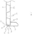
- FIG. 7 illustrates a cross-sectional view of a portion of a plastic composite board of Embodiment 4 of the present disclosure.
- FIG. 8 illustrates a cross-sectional view of a fastener in FIG. 7 .
- a plastic composite board comprises an upper board 10 , a lower board 20 , and a fastener 30 .
- the lower board 20 supports the upper board 10 .
- the upper board 10 and the lower board 20 are vacuum-formed plastics.
- the lower board 20 evenly comprises honeycomb-shaped holes to improve a strength of the lower board 20 .
- the upper board 10 comprises a panel 11 and a downward edge 12 disposed on a periphery of the panel 11 .
- the periphery of the panel 11 sinks downward and outward to define a first inclined surface 113 , and a periphery of the first inclined surface 113 extends outward to define a horizontal step surface 112 .
- the downward edge 12 extends downward from an outer edge of the horizontal step surface 112 .
- the fastener 30 comprises a buckle groove 31 , and an inner side of the buckle groove 31 are arranged to define an opening.
- the buckle groove 31 (e.g., the opening of the buckle groove 31 ) surrounds side portions of the upper board 10 and the lower board 20 to fixedly clamp the upper board 10 and the lower board 20 together, and the upper board 10 , the lower board 20 , and the fastener 30 (e.g., the buckle groove 31 ) define a whole member.
- An upper wall of the buckle groove 31 abuts the horizontal step surface 112 , and a top surface of the fastener 30 is lower than a top surface of the upper board 10 . That is, an upper wall of the buckle groove 31 is lower than the top surface of the panel 11 .
- the fastener 30 is obtained by bending a metal sheet.
- the fastener 30 comprises an upper press edge 32 , a side block edge 33 , a lower press edge 34 , and a vertical edge 35 connected in series.
- the upper press edge 32 , the side block edge 33 , and the lower press edge 34 define the buckle groove 31 .
- a lower end of the vertical edge 35 curls inward to define a curled edge 352 .
- the upper press edge 32 defines the upper wall of the buckle groove 31 , and the upper press edge 32 abuts the horizontal step surface 112 .
- a periphery of the lower board 20 comprises a reinforcing edge 22 horizontally disposed.
- the reinforcing edge 22 supports a lower side of the horizontal step surface 112 of the panel 11 .
- this embodiment differs Embodiment 1 in that an upper part of a fastener 40 comprises a buckle groove 48 .
- the function of the buckle groove 48 is the same as the function of the buckle groove 31 .
- the buckle groove 48 is configured to fixedly clamp the upper board 10 and lower board 20 .
- a lower part of the fastener 40 comprises a bottom support frame 401 .
- the fastener 40 comprises an upper press edge 41 , an outer block edge 42 , a lower bottom edge 43 , an inner block edge 44 , a lower press edge 45 , and a connection edge 46 connected in series.
- the connection edge 46 abuts the outer block edge 42 .
- the outer block edge 42 , the lower bottom edge 43 , the inner block edge 44 , and the lower press edge 45 are arranged to define the bottom support frame 401 .
- the upper press edge 41 abuts the horizontal step surface 112
- the lower press edge 45 abuts the lower board 20 .
- the bottom support frame 401 of the fastener 40 can really enhance a strength of the fastener 40 .
- a fastener 50 is an aluminum member.
- the fastener 50 comprises a bottom support frame 52 , a side block edge 54 extending vertically upward from an outer end of a top surface of the bottom support frame 52 , and an upper press edge 56 extending horizontally inward from a top end of the side block edge 54 .
- the top surface of the bottom support frame 52 , the side block edge 54 , and the upper press edge 56 are arranged to define a buckle groove 51 .
- the function of the buckle groove 51 is the same as the function of the buckle groove 31 .
- the buckle groove 51 is configured to fixedly clamp the upper board 10 and the lower board 20 .
- the upper press edge 56 abuts the horizontal step surface 112
- the top surface of the bottom support frame 52 abuts the lower board 20 .
- An inner side of a lower portion of the bottom support frame 52 comprises a guide angle 58 to enable a width of a bottom surface of the bottom support frame 52 to be smaller than a width of the horizontal step surface 112 .
- the bottom surface of the bottom support frame 52 of the fastener 50 of an upper plastic composite board of the plurality of plastic composite boards is configured to be supported on the upper press edge 56 of the fastener 50 of a lower plastic composite board of the plurality of plastic composite boards
- the horizontal step surface 112 is configured to effectively prevent the upper plastic composite board from sliding leftward and rightward relative to the lower plastic composite board.
- a side of the bottom support frame 52 facing an inner side of the panel 11 defines a second inclined surface 521 extending upward and inward from a bottom of the side of the bottom support frame 52 , and the first inclined surface 113 cooperates with the second inclined surface 521 .
- this embodiment differs from Embodiment 3 in that an inner end of the top surface of the bottom support frame 52 extends horizontally inward to define a support board 59 to increase a support area of a lower board 20 a .
- the lower board 20 a comprises a honeycomb-shaped board 24 and an upward edge 26 connected to a periphery the honeycomb-shaped board 24 .
- the upward edge 26 abuts the downward edge 12 of the upper board 10 to further improve a strength of the plastic composite board.
Abstract
Description
Claims (11)
Applications Claiming Priority (3)
| Application Number | Priority Date | Filing Date | Title |
|---|---|---|---|
| CN201721526196.3 | 2017-11-15 | ||
| CN201721526196.3U CN207657291U (en) | 2017-11-15 | 2017-11-15 | A kind of composite panel of plastic material |
| PCT/CN2018/115532 WO2019096185A1 (en) | 2017-11-15 | 2018-11-15 | Plastic composite board |
Related Parent Applications (1)
| Application Number | Title | Priority Date | Filing Date |
|---|---|---|---|
| PCT/CN2018/115532 Continuation WO2019096185A1 (en) | 2017-11-15 | 2018-11-15 | Plastic composite board |
Publications (2)
| Publication Number | Publication Date |
|---|---|
| US20200275780A1 US20200275780A1 (en) | 2020-09-03 |
| US11140986B2 true US11140986B2 (en) | 2021-10-12 |
Family
ID=62945923
Family Applications (1)
| Application Number | Title | Priority Date | Filing Date |
|---|---|---|---|
| US16/875,099 Active US11140986B2 (en) | 2017-11-15 | 2020-05-15 | Plastic composite board |
Country Status (4)
| Country | Link |
|---|---|
| US (1) | US11140986B2 (en) |
| JP (1) | JP3229245U (en) |
| CN (1) | CN207657291U (en) |
| WO (1) | WO2019096185A1 (en) |
Cited By (4)
| Publication number | Priority date | Publication date | Assignee | Title |
|---|---|---|---|---|
| US20200191331A1 (en) * | 2017-08-30 | 2020-06-18 | Luhao Leng | Single-layer plastic composite board |
| US20220354256A1 (en) * | 2020-09-29 | 2022-11-10 | New-Tec Integration (Xiamen) Co., Ltd. | Foldable plastic-steel chair |
| US20230148752A1 (en) * | 2021-11-12 | 2023-05-18 | Mity-Lite, Inc. | Table with Floating Perimeter Support |
| US11684159B2 (en) | 2017-08-30 | 2023-06-27 | New-Tec Integration (Xiamen) Co., Ltd. | Composite structural board |
Families Citing this family (4)
| Publication number | Priority date | Publication date | Assignee | Title |
|---|---|---|---|---|
| CN205093820U (en) | 2015-09-16 | 2016-03-23 | 厦门新技术集成有限公司 | Frame structure of table |
| CN207657291U (en) * | 2017-11-15 | 2018-07-27 | 厦门新技术集成有限公司 | A kind of composite panel of plastic material |
| CN111568035B (en) | 2019-02-15 | 2023-10-27 | 厦门新技术集成有限公司 | Composite panel and table with same |
| CN115336871A (en) * | 2021-09-01 | 2022-11-15 | 厦门新技术集成有限公司 | Composite board, furniture and manufacturing method |
Citations (16)
| Publication number | Priority date | Publication date | Assignee | Title |
|---|---|---|---|---|
| US2353777A (en) * | 1941-10-17 | 1944-07-18 | Tracy Mfg Company | Table-top construction |
| US2940805A (en) * | 1958-12-29 | 1960-06-14 | American Seating Co | Table top construction |
| US2981579A (en) * | 1957-05-06 | 1961-04-25 | Shwayder Bros Inc | Top for folding tables and the like |
| US3294353A (en) * | 1964-03-27 | 1966-12-27 | Carl E Rowe | Trim means or a border edge covering |
| EP0330228A2 (en) | 1988-02-25 | 1989-08-30 | Mitsubishi Plastics Industries Limited | Method for folding a plastic sheet |
| US5173348A (en) * | 1990-11-07 | 1992-12-22 | Krueger International, Inc. | Table edging system |
| US5551352A (en) * | 1994-02-25 | 1996-09-03 | Mecalit Gmbh Kunststoffverarbeitung | Table or cover plate |
| US5947037A (en) * | 1998-01-19 | 1999-09-07 | Krueger International, Inc. | Portable folding table incorporating a lightweight core |
| US6694897B2 (en) * | 2001-12-08 | 2004-02-24 | Cosco Management, Inc. | Table |
| CN201299266Y (en) | 2008-11-25 | 2009-09-02 | 冷鹭浩 | Desktop board |
| US7635114B2 (en) * | 2002-06-18 | 2009-12-22 | Mfs, Llc | Rotationally molded, reinforced decorative fence post and method of making same |
| US8181579B2 (en) * | 2008-08-25 | 2012-05-22 | New-Tec Integration (Xiamen) Co., Ltd. | Plastic and wood composite tabletop |
| CN205162320U (en) | 2015-11-13 | 2016-04-20 | 厦门新技术集成有限公司 | Plastic uptake table |
| CN106363912A (en) | 2016-08-31 | 2017-02-01 | 厦门新技术集成有限公司 | Covering method of composite board |
| US9750340B2 (en) * | 2015-02-11 | 2017-09-05 | Dorel Home Furnishings, Inc. | Banquet table |
| CN207657291U (en) | 2017-11-15 | 2018-07-27 | 厦门新技术集成有限公司 | A kind of composite panel of plastic material |
-
2017
- 2017-11-15 CN CN201721526196.3U patent/CN207657291U/en active Active
-
2018
- 2018-11-15 WO PCT/CN2018/115532 patent/WO2019096185A1/en active Application Filing
- 2018-11-15 JP JP2020600069U patent/JP3229245U/en active Active
-
2020
- 2020-05-15 US US16/875,099 patent/US11140986B2/en active Active
Patent Citations (16)
| Publication number | Priority date | Publication date | Assignee | Title |
|---|---|---|---|---|
| US2353777A (en) * | 1941-10-17 | 1944-07-18 | Tracy Mfg Company | Table-top construction |
| US2981579A (en) * | 1957-05-06 | 1961-04-25 | Shwayder Bros Inc | Top for folding tables and the like |
| US2940805A (en) * | 1958-12-29 | 1960-06-14 | American Seating Co | Table top construction |
| US3294353A (en) * | 1964-03-27 | 1966-12-27 | Carl E Rowe | Trim means or a border edge covering |
| EP0330228A2 (en) | 1988-02-25 | 1989-08-30 | Mitsubishi Plastics Industries Limited | Method for folding a plastic sheet |
| US5173348A (en) * | 1990-11-07 | 1992-12-22 | Krueger International, Inc. | Table edging system |
| US5551352A (en) * | 1994-02-25 | 1996-09-03 | Mecalit Gmbh Kunststoffverarbeitung | Table or cover plate |
| US5947037A (en) * | 1998-01-19 | 1999-09-07 | Krueger International, Inc. | Portable folding table incorporating a lightweight core |
| US6694897B2 (en) * | 2001-12-08 | 2004-02-24 | Cosco Management, Inc. | Table |
| US7635114B2 (en) * | 2002-06-18 | 2009-12-22 | Mfs, Llc | Rotationally molded, reinforced decorative fence post and method of making same |
| US8181579B2 (en) * | 2008-08-25 | 2012-05-22 | New-Tec Integration (Xiamen) Co., Ltd. | Plastic and wood composite tabletop |
| CN201299266Y (en) | 2008-11-25 | 2009-09-02 | 冷鹭浩 | Desktop board |
| US9750340B2 (en) * | 2015-02-11 | 2017-09-05 | Dorel Home Furnishings, Inc. | Banquet table |
| CN205162320U (en) | 2015-11-13 | 2016-04-20 | 厦门新技术集成有限公司 | Plastic uptake table |
| CN106363912A (en) | 2016-08-31 | 2017-02-01 | 厦门新技术集成有限公司 | Covering method of composite board |
| CN207657291U (en) | 2017-11-15 | 2018-07-27 | 厦门新技术集成有限公司 | A kind of composite panel of plastic material |
Non-Patent Citations (1)
| Title |
|---|
| International Search Report and Written Opinion with English Translation of ISR, cited in PCT/CN2018/115532 dated Feb. 26, 2019, 15 pages. |
Cited By (6)
| Publication number | Priority date | Publication date | Assignee | Title |
|---|---|---|---|---|
| US20200191331A1 (en) * | 2017-08-30 | 2020-06-18 | Luhao Leng | Single-layer plastic composite board |
| US11684159B2 (en) | 2017-08-30 | 2023-06-27 | New-Tec Integration (Xiamen) Co., Ltd. | Composite structural board |
| US11754224B2 (en) * | 2017-08-30 | 2023-09-12 | New-Tec Integration (Xiamen) Co., Ltd. | Single-layer plastic composite board |
| US20220354256A1 (en) * | 2020-09-29 | 2022-11-10 | New-Tec Integration (Xiamen) Co., Ltd. | Foldable plastic-steel chair |
| US20230148752A1 (en) * | 2021-11-12 | 2023-05-18 | Mity-Lite, Inc. | Table with Floating Perimeter Support |
| US11839302B2 (en) * | 2021-11-12 | 2023-12-12 | Mity-Lite, Inc. | Table with floating perimeter support |
Also Published As
| Publication number | Publication date |
|---|---|
| WO2019096185A1 (en) | 2019-05-23 |
| JP3229245U (en) | 2020-12-03 |
| CN207657291U (en) | 2018-07-27 |
| US20200275780A1 (en) | 2020-09-03 |
Similar Documents
| Publication | Publication Date | Title |
|---|---|---|
| US11140986B2 (en) | Plastic composite board | |
| US20230276938A1 (en) | Hollow panel furniture | |
| US7869224B1 (en) | Housing structure for pluggable transceiver module | |
| US20210177138A1 (en) | Table panel | |
| CN111568035B (en) | Composite panel and table with same | |
| US20090165211A1 (en) | Inflatable Bed | |
| CN211408005U (en) | Plastic uptake table | |
| US11930291B2 (en) | Display module and television | |
| US9816689B2 (en) | Backlight back plate, adhesive-metal integrated structure of backlight source, backlight source, and display panel | |
| US10648611B2 (en) | Display stand | |
| CN215186609U (en) | Mounting bracket and assembly structure of photovoltaic module | |
| JP3130243U (en) | Cover profile strip | |
| CN206021805U (en) | A kind of display screen and display device | |
| US10531589B2 (en) | Server casing and plate connecting structure thereof | |
| KR100622344B1 (en) | Shelf supporter for assembly rack system | |
| JP2012031653A (en) | Support tool for building | |
| CN211959531U (en) | Loudspeaker | |
| US9603278B1 (en) | Server casing and plate connecting structure thereof | |
| TWM543848U (en) | Storage box stacking engagement structure | |
| CN211200896U (en) | Multifunctional square aluminum beam | |
| US11567545B2 (en) | Display device and frame module thereof | |
| CN209677983U (en) | A kind of showing stand with combined type objective table | |
| CN217157000U (en) | Frameless curved surface display module | |
| AU2018100308A4 (en) | Hollow desk panel | |
| KR200408932Y1 (en) | Reinforcement assembly member for furniture |
Legal Events
| Date | Code | Title | Description |
|---|---|---|---|
| AS | Assignment |
Owner name: NEW-TEC INTEGRATION (XIAMEN) CO., LTD., CHINA Free format text: ASSIGNMENT OF ASSIGNORS INTEREST;ASSIGNOR:LENG, LUHAO;REEL/FRAME:052672/0819 Effective date: 20200515 |
|
| FEPP | Fee payment procedure |
Free format text: ENTITY STATUS SET TO UNDISCOUNTED (ORIGINAL EVENT CODE: BIG.); ENTITY STATUS OF PATENT OWNER: SMALL ENTITY |
|
| FEPP | Fee payment procedure |
Free format text: ENTITY STATUS SET TO SMALL (ORIGINAL EVENT CODE: SMAL); ENTITY STATUS OF PATENT OWNER: SMALL ENTITY |
|
| STPP | Information on status: patent application and granting procedure in general |
Free format text: NON FINAL ACTION MAILED |
|
| STPP | Information on status: patent application and granting procedure in general |
Free format text: RESPONSE TO NON-FINAL OFFICE ACTION ENTERED AND FORWARDED TO EXAMINER |
|
| STPP | Information on status: patent application and granting procedure in general |
Free format text: NOTICE OF ALLOWANCE MAILED -- APPLICATION RECEIVED IN OFFICE OF PUBLICATIONS |
|
| STPP | Information on status: patent application and granting procedure in general |
Free format text: PUBLICATIONS -- ISSUE FEE PAYMENT VERIFIED |
|
| STCF | Information on status: patent grant |
Free format text: PATENTED CASE |