US11139729B2 - Magnetic coupling - Google Patents
Magnetic coupling Download PDFInfo
- Publication number
- US11139729B2 US11139729B2 US16/657,004 US201916657004A US11139729B2 US 11139729 B2 US11139729 B2 US 11139729B2 US 201916657004 A US201916657004 A US 201916657004A US 11139729 B2 US11139729 B2 US 11139729B2
- Authority
- US
- United States
- Prior art keywords
- magnets
- rotor
- magnet insertion
- insertion recesses
- pole
- Prior art date
- Legal status (The legal status is an assumption and is not a legal conclusion. Google has not performed a legal analysis and makes no representation as to the accuracy of the status listed.)
- Active, expires
Links
- 230000008878 coupling Effects 0.000 title claims abstract description 51
- 238000010168 coupling process Methods 0.000 title claims abstract description 51
- 238000005859 coupling reaction Methods 0.000 title claims abstract description 51
- 238000003780 insertion Methods 0.000 claims abstract description 80
- 230000037431 insertion Effects 0.000 claims abstract description 80
- 238000003491 array Methods 0.000 abstract description 2
- 230000005540 biological transmission Effects 0.000 description 7
- 238000002955 isolation Methods 0.000 description 1
- 238000004519 manufacturing process Methods 0.000 description 1
- 238000012986 modification Methods 0.000 description 1
- 230000004048 modification Effects 0.000 description 1
- 238000007789 sealing Methods 0.000 description 1
- 239000000126 substance Substances 0.000 description 1
Images


Classifications
-
- H—ELECTRICITY
- H02—GENERATION; CONVERSION OR DISTRIBUTION OF ELECTRIC POWER
- H02K—DYNAMO-ELECTRIC MACHINES
- H02K49/00—Dynamo-electric clutches; Dynamo-electric brakes
- H02K49/10—Dynamo-electric clutches; Dynamo-electric brakes of the permanent-magnet type
- H02K49/104—Magnetic couplings consisting of only two coaxial rotary elements, i.e. the driving element and the driven element
- H02K49/106—Magnetic couplings consisting of only two coaxial rotary elements, i.e. the driving element and the driven element with a radial air gap
-
- H—ELECTRICITY
- H02—GENERATION; CONVERSION OR DISTRIBUTION OF ELECTRIC POWER
- H02K—DYNAMO-ELECTRIC MACHINES
- H02K1/00—Details of the magnetic circuit
- H02K1/06—Details of the magnetic circuit characterised by the shape, form or construction
- H02K1/22—Rotating parts of the magnetic circuit
- H02K1/27—Rotor cores with permanent magnets
- H02K1/2706—Inner rotors
- H02K1/272—Inner rotors the magnetisation axis of the magnets being perpendicular to the rotor axis
- H02K1/274—Inner rotors the magnetisation axis of the magnets being perpendicular to the rotor axis the rotor consisting of two or more circumferentially positioned magnets
- H02K1/2753—Inner rotors the magnetisation axis of the magnets being perpendicular to the rotor axis the rotor consisting of two or more circumferentially positioned magnets the rotor consisting of magnets or groups of magnets arranged with alternating polarity
- H02K1/278—Surface mounted magnets; Inset magnets
-
- H—ELECTRICITY
- H02—GENERATION; CONVERSION OR DISTRIBUTION OF ELECTRIC POWER
- H02K—DYNAMO-ELECTRIC MACHINES
- H02K2213/00—Specific aspects, not otherwise provided for and not covered by codes H02K2201/00 - H02K2211/00
- H02K2213/03—Machines characterised by numerical values, ranges, mathematical expressions or similar information
Definitions
- the present disclosure relates to a magnetic coupling and, more particularly, to a magnetic coupling that can meet any of various specification requirements by employing magnets of the same shape.
- a coupling is shaft joint device which may be installed in a power transmission apparatus such as an industrial machine and an automation equipment to connect a drive shaft to a driven shaft to transfer torque with little deviation in rotation speeds between the drive shaft and the driven shaft.
- Conventional couplings include a gear coupling such as a spline, a diaphragm coupling, a flexible coupling, a magnetic coupling, and the like.
- the magnetic coupling connects physically separated shafts by using magnetic forces to transfer the torque between the shafts. Since the magnetic coupling allows a complete isolation of the axes, it is widely being used in applications which require sealing between the axes.
- the magnetic coupling is made using magnets of different shapes and dimensions suited for each power transmission apparatus to meet various specification requirements of the power transmission apparatuses. As the magnetic coupling and the magnets are manufactured according to the specification of the power transmission apparatus, it is difficult to share the magnets between the magnetic couplings having different specifications, which increases the manufacturing costs of the magnetic couplings.
- the present disclosure provides a magnetic coupling that can be manufactured to meet various specification requirements of the power transmission apparatuses by employing magnets which can be shared between the magnetic couplings.
- the present disclosure provides a magnetic coupling that can be manufactured to meet various specification requirements of the power transmission apparatuses by using the magnets of the same shape.
- an inner rotor for use in a magnetic coupling.
- the inner rotor includes: an inner rotor core having inner magnet insertion recesses formed in a two-dimensional array having m rows and n columns on an entire outer circumferential surface, where m and n are natural numbers larger than 3 and n is larger than m; an inner rotation shaft coupled to a center of an end face of the inner rotor core; and a plurality of inner magnets magnetized in a radial direction and each being installed in respective one of at least some of the inner magnet insertion recesses such that a magnetic north (N) pole of one or more of the plurality of inner magnets alternates with a magnetic south (S) pole of one or more of the plurality of inner magnets.
- N magnetic north
- S magnetic south
- Each of the inner magnet insertion recesses may have rectangular cross sections in longitudinal and transverse directions.
- the inner magnet insertion recesses in a column may be arranged in a direction parallel to a rotational axis of the inner rotor, and the inner magnet insertion recesses in a row may be arranged in a circumference of which plane is orthogonal with respect to the rotational axis of the inner rotor.
- the inner magnet insertion recesses arranged in a column may be provided with the inner magnets of a same polarity.
- an outer rotor for use in a magnetic coupling.
- the outer rotor includes: an outer rotor core having a cavity for receiving an inner rotor and outer magnet insertion recesses formed in a two-dimensional array having x rows and y columns on an entire inner circumferential surface, where x and y are natural numbers larger than 3 and y is larger than x; an outer rotation shaft coupled to the outer rotor core and extending axially in a direction opposite to the cavity; and a plurality of outer magnets magnetized in a radial direction and each being installed in respective one of at least some of the outer magnet insertion recesses such that the N pole of one or more of the plurality of outer magnets alternates with the S pole of one or more of the plurality of outer magnets.
- the outer magnet insertion recesses in a column may be arranged in a direction parallel to a rotational axis of the outer rotor, and the outer magnet insertion recesses in a row may be arranged in a circumference of which plane is orthogonal with respect to the rotational axis of the outer rotor.
- the outer magnet insertion recesses arranged in a column may be provided with the outer magnets of a same polarity.
- the magnetic coupling includes: an outer rotor having a cavity for receiving an inner rotor and an inner circumferential surface on which a plurality outer magnets are installed; and the inner rotor placed in the cavity of the outer rotor and having an outer circumferential surface on which a plurality inner magnets are installed.
- the present disclosure enables to provide a magnetic coupling that can meet various specification requirements by magnets of the same shape and dimension.
- the magnetic coupling can meet various specification requirements by forming the magnet insertion recesses in a two-dimensional arrays having a plurality of rows and a plurality of columns in an area where the magnets are to be is installed and inserting the magnets selectively into the magnet insertion recesses according to the specification requirements.
- the magnets inserted into the magnet insertion recesses have the same shape, the magnets can be shared between the magnetic couplings having different specifications from each other.
- the specification of the magnetic coupling may be adjusted further by changing the width and length of the magnets inserted into the magnet insertion recesses.
- the magnetic coupling of more various specifications can be manufactured easily by adjusting the number of the magnets inserted into the magnet insertion recesses as well as the shape of the magnets.
- FIG. 1 is an exploded view of a magnetic coupling according to an exemplary embodiment of the present disclosure
- FIG. 2 is a perspective view of the magnetic coupling according to an exemplary embodiment of the present disclosure in an assembled state
- FIG. 3 is a perspective view of an inner rotor core of an inner rotor shown in FIG.
- FIG. 4 is a perspective view of the inner rotor shown in FIG. 1 ;
- FIGS. 5 to 7 are perspective views of the inner rotors having different inner magnet arrangements according to another exemplary embodiments of the present disclosure.
- FIG. 8 is a perspective view of an outer rotor shown in FIG. 1 .
- FIG. 1 is an exploded view of a magnetic coupling according to an exemplary embodiment of the present disclosure
- FIG. 2 is a perspective view of the magnetic coupling in an assembled state.
- the magnetic coupling 100 includes an outer rotor 10 and an inner rotor 20 .
- the outer rotor 10 has a shape of a cylinder of which one end is closed to form a cavity 13 , into which the inner rotor 20 is inserted.
- a plurality of outer magnets 17 may be disposed on an inner circumferential surface of the cavity 13 of the outer rotor 10 .
- the inner rotor 20 is inserted into the cavity 13 of the outer rotor 10 , and a plurality of inner magnets 27 may be disposed on an outer circumferential surface of the inner rotor 20 .
- Each of the outer magnets 17 and the inner magnets 27 is installed to be located close to, but spaced apart from, corresponding one of the inner magnets 27 and the outer magnets 17 .
- the outer rotor 10 and the inner rotor 20 have an outer rotation shaft 12 and an inner rotation shaft 22 , respectively, separated physically from each other and extending in opposite directions on a same virtual axis.
- the outer rotation shaft 12 and the inner rotation shaft 22 connected by magnetic forces between the outer magnets 17 and the inner magnets 27 to transfer a rotational torque.
- Magnet insertion recesses 15 or 25 may be formed on the inner circumferential surface of the outer rotor 10 or the outer circumferential surface of the inner rotor 20 , respectively.
- the outer magnet insertion recesses 15 may be formed on an entire inner circumferential surface of the outer rotor 10
- the inner magnet insertion recesses 25 may be formed on an entire outer circumferential surface of the inner rotor 20 . All or some of the outer and inner magnet insertion recesses 15 or 25 are inserted with magnets 17 or 27 according to the specification required for the magnetic coupling 100 to be manufactured. Thus, some of the magnet insertion recesses 15 and 25 may be left empty without the magnets 17 and 27 being inserted.
- the magnet insertion recesses 15 and 25 are formed in a two-dimensional array consisting of a plurality of rows and columns.
- the magnets 17 and 27 may be inserted into the magnet insertion recesses 15 and 25 .
- the specification required for the magnetic coupling 100 can be met by adjusting the length or width of the magnets 17 and 27 inserted into the magnet insertion recesses 15 and 25 .
- the specification required for the magnetic coupling 100 can be met by adjusting the number of the magnets 17 and 27 inserted into the magnet insertion recesses 15 and 25 . Accordingly, the magnet coupling 100 according to the present embodiment can met the specification required for the power transmission apparatus by using the magnets 17 and 27 having the same shape. That is, the magnetic coupling 100 that meets a certain specification requirement can be provided by inserting as many magnets 17 and 27 as necessary according to the specification requirement into the plurality of magnet insertion recesses 15 and 25 formed in the outer rotor 10 and the inner rotor 20 .
- the magnets 17 and 27 inserted into the magnet insertion recesses 15 and 25 have the same shape, the magnets 17 and 27 can be shared between the magnetic couplings 100 having different specification requirements.
- the specification of the magnetic coupling 100 may be adjusted further by changing the width and length of the magnets 17 and 27 inserted into the magnet insertion recesses 15 and 25 .
- the magnetic coupling 100 of more various specifications can be manufactured easily by adjusting the number of the magnets 17 and 27 inserted into the magnet insertion recesses 15 and 25 as well as the shape of the magnets 17 and 27 .
- the magnet insertion recesses 15 and 25 into which the magnets 17 and 27 can be inserted are formed in the outer rotor 10 and the inner rotor 20 , respectively, according to the present embodiment.
- the outer rotor 10 and the inner rotor 20 according to the present embodiment will be described in more detail with reference to FIGS. 3-8 .
- FIG. 3 is a perspective view of an inner rotor core 21 of the inner rotor 20 .
- FIG. 4 is a perspective view of the inner rotor 20 shown in FIG. 1 .
- the inner rotor 20 includes the inner rotor core 21 , the inner rotation shaft 22 , and the plurality of inner magnets 27 .
- the inner rotor core 21 has the inner magnet insertion recesses 25 formed in the two-dimensional array having m rows and n columns, where m and n are natural numbers larger than 3 and n is larger than m, on its entire outer circumferential surface.
- the inner rotation shaft 22 may be coupled to the inner rotor core 21 to extend from a center of an end face of the inner rotor core 21 .
- the plurality of inner magnets 27 are installed in at least some of the inner magnet insertion recesses 25 .
- the inner magnets 27 may be installed such that a magnetic north (N) pole of one or a plurality of inner magnets 27 alternates with a magnetic south (S) pole of one or a plurality of inner magnets 27 on the outer circumferential surface of the inner rotor 20 .
- the inner rotor core 21 has a cylindrical shape, and a shaft insertion hole 23 may be formed to penetrate the centers of the planar sides of the inner rotor core 21 along its rotational axis so that the inner rotation shaft 22 is inserted into the shaft insertion hole 23 .
- the inner magnet insertion recesses 25 formed on the entire outer circumferential surface may have rectangular cross sections in longitudinal and transverse directions, for example.
- the inner magnet insertion recesses 25 in a column are arranged in a direction parallel to the rotational axis of the inner rotor 20 .
- the inner magnet insertion recesses 25 in a row are arranged in a circumference of which plane is orthogonal with respect to the rotational axis of the inner rotor 20 .
- the inner magnets 27 are magnetized in a radial direction. Some of the inner magnets 27 may be disposed such that their N poles are exposed to the outer circumferential surface of the inner rotor core 21 , while the other inner magnets 27 may be disposed such that their S poles are exposed to the outer circumferential surface of the inner rotor core 21 .
- N-pole magnet a magnet of which N pole is exposed to the outer circumferential surface
- S-pole magnet a magnet of which S pole is exposed to the outer circumferential surface
- the inner magnets 27 may be provided such that the N pole of one or a plurality of inner magnets 27 alternates with the S pole of one or a plurality of inner magnets 27 on the outer circumferential surface of the inner rotor 20 .
- the inner magnets 27 may be installed such that one or more N-pole magnets 28 alternate with one or more S-pole magnets 29 .
- the inner magnet insertion recesses 25 arranged in a column are provided with the inner magnets 27 of a same polarity.
- the inner magnets 27 are inserted into all the inner magnet insertion recesses 25 .
- every three inner N-pole magnets 28 alternate with a single inner S-pole magnet 29 in a certain row of the inner magnet insertion recesses 25 .
- the inner rotor 20 may be assembled in a manner similar to an assembly of tessellating pieces onto a puzzle board in a tiling puzzle.
- the inner rotor core 21 may correspond to the puzzle board
- the inner magnet insertion recesses 25 may correspond to piece marks of the puzzle board
- the inner magnets 27 may correspond to the pieces.
- the inner rotor 20 may be manufactured by forming the inner magnet insertion recesses 25 on the inner rotor core 21 and inserting the inner magnets 27 into the inner magnet insertion recesses 25 .
- the specification of the magnetic coupling 100 can be adjusted by changing the number and arrangement of the inner magnets 27 installed in the inner rotor core 21 .
- the inner magnets 27 are inserted into all the inner magnet insertion recesses 25 and every three inner N-pole magnets 28 alternate with a single inner S-pole magnet 29 circumferentially in the embodiment described above, the present disclosure is not limited thereto.
- the inner magnets 27 may be arranged in various ways as shown in FIGS. 5-7 according to the specification required in the application of the magnetic coupling 100 .
- FIGS. 5-7 are perspective views of the inner rotors 20 a - 20 c having different inner magnet arrangements according to another exemplary embodiments.
- the inner magnets 27 may be arranged on the inner rotor 20 a such that every two inner N-pole magnets 28 alternate with a single inner S-pole magnet 29 and a vacant position in a circumferential direction. That is, a combination of two inner N-pole magnets 28 and a single inner S-pole magnet 29 is repeatedly arranged, and one inner magnet insertion recess 25 a where no inner magnet 27 is inserted is located between the combinations.
- the inner magnets 27 are arranged such that every three inner N-pole magnets 28 alternate with a single inner S-pole magnet 29 in the circumferential direction.
- the inner rotor 20 b includes a series of vacant positions arranged in the circumferential direction. That is, the inner rotor 20 b includes one or more rows of vacant positions where no inner magnet 27 is inserted.
- the inner rotor 20 b includes five rows of the inner magnet insertion recesses 25 . Among the five rows of the inner magnet insertion recesses 25 , three rows are filled with the inner magnets 27 while the remaining two rows of the insertion recesses 25 b are vacant.
- the inner magnets 27 are inserted into all the inner magnet insertion recesses 25 on the inner rotor 20 c .
- the inner magnets 27 are arranged such that every two inner N-pole magnets 28 alternate with two inner S-pole magnet 29 in the circumferential direction. That is, the same number of inner N-pole magnets 28 and the inner S-pole magnets 29 are alternately arranged on the inner rotor 20 c.
- the inner rotor may have an arrangement of the inner magnets 27 reverse to that shown in FIG. 4 . That is, the inner magnets 27 are may be inserted into all the inner magnet insertion recesses 25 on the inner rotor 20 c , and the inner magnets 27 may be arranged such that every three inner S-pole magnets 29 alternate with a single inner N-pole magnet 28 in the circumferential direction.
- the inner rotor cores 20 - 20 c have the inner magnet insertion recesses 25 formed in the two-dimensional array having m rows and n columns.
- the arrangement of the inner magnets 27 including the arrangement of the vacant row or the vacant column and the alternating pattern of the column of the inner N-pole magnets 28 and the column of the inner S-pole magnets 29 may be adjusted as necessary.
- the specification required for the magnetic coupling 100 can be met by adjusting the arrangement of the inner magnets 27 .
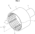
- FIG. 8 is a perspective view of the outer rotor 10 shown in FIG. 1 .
- the outer rotor 10 includes an outer rotor core 11 , an outer rotation shaft 12 , and a plurality of outer magnets 17 .
- the outer rotor core 11 has a cylindrical shape with an opening formed on one side and is closed by an end plate on the other side.
- the cylindrical side wall and the end plate of the outer rotor core 11 define the cavity 13 for receiving the inner rotor 20 .
- the opening of the outer rotor core 11 serves as an entrance of the cavity 13 and allows the inner rotor 20 to be inserted into the cavity 13 .
- the outer rotation shaft 12 extends axially in the direction opposite to the cavity 13 from a center of an outer surface of the end plate of the outer rotor core 11 .
- the outer rotor core 11 has the outer magnet insertion recesses 15 formed in a two-dimensional array having x rows and y columns, where x and y are natural numbers larger than 3 and y is larger than x, on an entire inner circumferential surface of the cavity 13 .
- the plurality of outer magnets 17 are installed in at least some of the outer magnet insertion recesses 15 such that the N pole of one or a plurality of outer magnets 17 alternates with the S pole of one or a plurality of outer magnets 27 .
- the outer magnet insertion recesses 15 are formed on the entire inner circumferential surface of the outer rotor core 11 .
- the outer magnet insertion recesses 15 may have rectangular cross sections in the longitudinal and the transverse directions, for example.
- Each of the outer magnet insertion recesses 15 may be formed to face a corresponding one of the inner magnet insertion recesses 25 .
- the outer magnet insertion recesses 15 in a column are arranged in a direction parallel to the rotational axis of the outer rotor 10 .
- the outer magnet insertion recesses 15 in a row are arranged in a circumference of which plane is orthogonal with respect to the rotational axis of the outer rotor 10 .
- the outer magnets 17 are magnetized in the radial direction. Some of the outer magnets 17 may be disposed such that their N poles are exposed to the inner circumferential surface of the outer rotor core 11 , while the other outer magnets 17 may be disposed such that their S poles are exposed to the inner circumferential surface of the outer rotor core 11 .
- the outer magnets 17 may be provided such that the N pole of one or a plurality of outer magnets 17 alternates with the S pole of one or a plurality of outer magnets 17 on the inner circumferential surface of the outer rotor core 11 . In other words, the outer magnets 17 may be installed such that one or more outer N-pole magnets 18 alternate with one or more outer S-pole magnets 19 .
- the outer magnet insertion recesses 15 arranged in a column are provided with the outer magnets 17 of a same polarity.
- the polarity of the outer magnet 17 may be chosen to be opposite to that of the inner magnet 27 facing the outer magnet 17 so that an attraction force acts between the outer magnet 17 and the inner magnet 27 .
- the outer magnets 17 may be provided such that every three outer S-pole magnets 19 alternate with a single outer N-pole magnet 18 in the row.
- the magnetic coupling 100 can transfer torque received by one of the outer rotation shaft 12 and the inner rotation shaft 22 separated from each other to the other one of the outer rotation shaft 12 and the inner rotation shaft 22 by a magnetic force between the outer magnet 17 and the inner magnet 27 .
- the magnet insertion recesses 15 and 25 for inserting the magnets 17 and 27 are formed on both the outer rotor 10 and the inner rotor 20 in the embodiment described above, the present disclosure is not limited thereto.
- the magnet insertion recesses may be formed on either the outer rotor 10 or the inner rotor 20 .
- the outer magnets provided in the outer rotor may have the same shape as each other.
- the inner magnets provided in the inner rotor may have the same shape as each other.
- the outer magnet and the inner magnet may have the same shape as each other.
- the outer magnet and the inner magnet may have different shapes from each other.
Landscapes
- Engineering & Computer Science (AREA)
- Power Engineering (AREA)
- Permanent Field Magnets Of Synchronous Machinery (AREA)
Abstract
Description
Claims (9)
Applications Claiming Priority (2)
| Application Number | Priority Date | Filing Date | Title |
|---|---|---|---|
| KR10-2019-0048954 | 2019-04-26 | ||
| KR1020190048954A KR102302463B1 (en) | 2019-04-26 | 2019-04-26 | Magnetic coupling |
Publications (2)
| Publication Number | Publication Date |
|---|---|
| US20200343805A1 US20200343805A1 (en) | 2020-10-29 |
| US11139729B2 true US11139729B2 (en) | 2021-10-05 |
Family
ID=72921952
Family Applications (1)
| Application Number | Title | Priority Date | Filing Date |
|---|---|---|---|
| US16/657,004 Active 2040-01-01 US11139729B2 (en) | 2019-04-26 | 2019-10-18 | Magnetic coupling |
Country Status (2)
| Country | Link |
|---|---|
| US (1) | US11139729B2 (en) |
| KR (1) | KR102302463B1 (en) |
Cited By (3)
| Publication number | Priority date | Publication date | Assignee | Title |
|---|---|---|---|---|
| US20200386289A1 (en) * | 2019-01-09 | 2020-12-10 | Green Wave Power Systems Llc | Magnetically-coupled torque-assist apparatus |
| US11646630B2 (en) | 2021-09-30 | 2023-05-09 | Green Wave Power Systems Llc | System and method for generating rotation of a body to generate energy and reduce climate change |
| US11776722B2 (en) | 2019-01-09 | 2023-10-03 | Green Wave Power Systems Llc | System and method for perturbing a permanent magnet asymmetric field to move a body |
Families Citing this family (1)
| Publication number | Priority date | Publication date | Assignee | Title |
|---|---|---|---|---|
| US11561359B2 (en) * | 2018-02-09 | 2023-01-24 | Carl Zeiss Meditec Ag | Balancing device for rotary apparatus |
Citations (4)
| Publication number | Priority date | Publication date | Assignee | Title |
|---|---|---|---|---|
| JPH05168222A (en) | 1991-12-18 | 1993-07-02 | Heriosu:Kk | Excessive torque prevention method and prevention device |
| JP2014100027A (en) * | 2012-11-15 | 2014-05-29 | Hirotoshi Tochihira | Magnet motor and drive mechanism |
| KR101501549B1 (en) | 2013-10-30 | 2015-03-12 | 한국에너지기술연구원 | Magnetic Coupling And Fluid Pump Using The Same |
| KR101846343B1 (en) | 2017-02-03 | 2018-05-18 | 전남대학교 산학협력단 | The magnetic coupling torque limiter |
-
2019
- 2019-04-26 KR KR1020190048954A patent/KR102302463B1/en active Active
- 2019-10-18 US US16/657,004 patent/US11139729B2/en active Active
Patent Citations (4)
| Publication number | Priority date | Publication date | Assignee | Title |
|---|---|---|---|---|
| JPH05168222A (en) | 1991-12-18 | 1993-07-02 | Heriosu:Kk | Excessive torque prevention method and prevention device |
| JP2014100027A (en) * | 2012-11-15 | 2014-05-29 | Hirotoshi Tochihira | Magnet motor and drive mechanism |
| KR101501549B1 (en) | 2013-10-30 | 2015-03-12 | 한국에너지기술연구원 | Magnetic Coupling And Fluid Pump Using The Same |
| KR101846343B1 (en) | 2017-02-03 | 2018-05-18 | 전남대학교 산학협력단 | The magnetic coupling torque limiter |
Non-Patent Citations (2)
| Title |
|---|
| Korean Office Action dated Mar. 17, 2021 in Courterpart Korean Patent Application No. 10-2019-0048954 (Seven pages in Korean). |
| Machine translation JP201400027 (Year: 2014). * |
Cited By (4)
| Publication number | Priority date | Publication date | Assignee | Title |
|---|---|---|---|---|
| US20200386289A1 (en) * | 2019-01-09 | 2020-12-10 | Green Wave Power Systems Llc | Magnetically-coupled torque-assist apparatus |
| US11732769B2 (en) * | 2019-01-09 | 2023-08-22 | Green Wave Power Systems Llc | Magnetically-coupled torque-assist apparatus |
| US11776722B2 (en) | 2019-01-09 | 2023-10-03 | Green Wave Power Systems Llc | System and method for perturbing a permanent magnet asymmetric field to move a body |
| US11646630B2 (en) | 2021-09-30 | 2023-05-09 | Green Wave Power Systems Llc | System and method for generating rotation of a body to generate energy and reduce climate change |
Also Published As
| Publication number | Publication date |
|---|---|
| US20200343805A1 (en) | 2020-10-29 |
| KR20200125134A (en) | 2020-11-04 |
| KR102302463B1 (en) | 2021-09-15 |
Similar Documents
| Publication | Publication Date | Title |
|---|---|---|
| US11139729B2 (en) | Magnetic coupling | |
| EP2549624B1 (en) | Rotor core for motor | |
| US5051635A (en) | Ball-splined shaft assembly | |
| US20130285497A1 (en) | Magnetic drive apparatus | |
| JP2005269709A (en) | Magnetic rotation transmitting unit and sealed agitator | |
| JP5087583B2 (en) | Electric motor and method of manufacturing electric motor | |
| KR950015919A (en) | Linear-rotary compound stepping motor | |
| SG192960A1 (en) | Magnetic couplings | |
| KR101296877B1 (en) | Power transmission mechanism | |
| JPH07308060A (en) | Magnetic coupling device | |
| JP2004248443A (en) | Dc brushless motor | |
| US11239535B2 (en) | Waveguide switch rotor with improved isolation | |
| CN101589537A (en) | Electric motor, rotor structure and magnetic equipment | |
| WO2015115694A1 (en) | Coaxial magnetic gear | |
| KR101059268B1 (en) | Magnetic coupling for conveyor | |
| KR101282613B1 (en) | Speed increasing or decreasing device using permanent magnets | |
| EP3316451A1 (en) | Motor device | |
| KR100944543B1 (en) | Coupler for Magnet Pump | |
| JP2025061701A (en) | Systems and methods for magnetic rotary coupling devices - Patents.com | |
| JP2007074900A (en) | Magnetic rotation transmission unit and sealed stirring arrangement | |
| KR19990084233A (en) | Magnetic coupling device for power transmission | |
| KR20210023335A (en) | Magnetic coupling for conveyor | |
| JPH1155932A (en) | Non-contact power transmission mechanism | |
| JP4854625B2 (en) | Load sensitive switching device | |
| SU864458A1 (en) | Contact-free magnetic reducing clutch |
Legal Events
| Date | Code | Title | Description |
|---|---|---|---|
| AS | Assignment |
Owner name: KOREA ELECTRONICS TECHNOLOGY INSTITUTE, KOREA, REPUBLIC OF Free format text: ASSIGNMENT OF ASSIGNORS INTEREST;ASSIGNORS:RHYU, SEHYUN;SEO, JUNGMOO;LEE, JEONGJONG;AND OTHERS;REEL/FRAME:050759/0275 Effective date: 20191016 |
|
| FEPP | Fee payment procedure |
Free format text: ENTITY STATUS SET TO UNDISCOUNTED (ORIGINAL EVENT CODE: BIG.); ENTITY STATUS OF PATENT OWNER: SMALL ENTITY |
|
| FEPP | Fee payment procedure |
Free format text: ENTITY STATUS SET TO SMALL (ORIGINAL EVENT CODE: SMAL); ENTITY STATUS OF PATENT OWNER: SMALL ENTITY |
|
| STPP | Information on status: patent application and granting procedure in general |
Free format text: NON FINAL ACTION MAILED |
|
| STPP | Information on status: patent application and granting procedure in general |
Free format text: RESPONSE TO NON-FINAL OFFICE ACTION ENTERED AND FORWARDED TO EXAMINER |
|
| STPP | Information on status: patent application and granting procedure in general |
Free format text: NOTICE OF ALLOWANCE MAILED -- APPLICATION RECEIVED IN OFFICE OF PUBLICATIONS |
|
| STPP | Information on status: patent application and granting procedure in general |
Free format text: PUBLICATIONS -- ISSUE FEE PAYMENT RECEIVED |
|
| STPP | Information on status: patent application and granting procedure in general |
Free format text: PUBLICATIONS -- ISSUE FEE PAYMENT VERIFIED |
|
| STCF | Information on status: patent grant |
Free format text: PATENTED CASE |
|
| MAFP | Maintenance fee payment |
Free format text: PAYMENT OF MAINTENANCE FEE, 4TH YR, SMALL ENTITY (ORIGINAL EVENT CODE: M2551); ENTITY STATUS OF PATENT OWNER: SMALL ENTITY Year of fee payment: 4 |