US11137182B2 - Thermostatic expansion valves including interchangeable metering pins - Google Patents
Thermostatic expansion valves including interchangeable metering pins Download PDFInfo
- Publication number
- US11137182B2 US11137182B2 US16/704,749 US201916704749A US11137182B2 US 11137182 B2 US11137182 B2 US 11137182B2 US 201916704749 A US201916704749 A US 201916704749A US 11137182 B2 US11137182 B2 US 11137182B2
- Authority
- US
- United States
- Prior art keywords
- metering pin
- expansion valve
- thermostatic expansion
- taper portion
- metering
- Prior art date
- Legal status (The legal status is an assumption and is not a legal conclusion. Google has not performed a legal analysis and makes no representation as to the accuracy of the status listed.)
- Active, expires
Links
Images


Classifications
-
- F—MECHANICAL ENGINEERING; LIGHTING; HEATING; WEAPONS; BLASTING
- F25—REFRIGERATION OR COOLING; COMBINED HEATING AND REFRIGERATION SYSTEMS; HEAT PUMP SYSTEMS; MANUFACTURE OR STORAGE OF ICE; LIQUEFACTION SOLIDIFICATION OF GASES
- F25B—REFRIGERATION MACHINES, PLANTS OR SYSTEMS; COMBINED HEATING AND REFRIGERATION SYSTEMS; HEAT PUMP SYSTEMS
- F25B41/00—Fluid-circulation arrangements
- F25B41/30—Expansion means; Dispositions thereof
- F25B41/31—Expansion valves
- F25B41/33—Expansion valves with the valve member being actuated by the fluid pressure, e.g. by the pressure of the refrigerant
- F25B41/335—Expansion valves with the valve member being actuated by the fluid pressure, e.g. by the pressure of the refrigerant via diaphragms
-
- F—MECHANICAL ENGINEERING; LIGHTING; HEATING; WEAPONS; BLASTING
- F25—REFRIGERATION OR COOLING; COMBINED HEATING AND REFRIGERATION SYSTEMS; HEAT PUMP SYSTEMS; MANUFACTURE OR STORAGE OF ICE; LIQUEFACTION SOLIDIFICATION OF GASES
- F25B—REFRIGERATION MACHINES, PLANTS OR SYSTEMS; COMBINED HEATING AND REFRIGERATION SYSTEMS; HEAT PUMP SYSTEMS
- F25B41/00—Fluid-circulation arrangements
- F25B41/30—Expansion means; Dispositions thereof
- F25B41/31—Expansion valves
-
- F—MECHANICAL ENGINEERING; LIGHTING; HEATING; WEAPONS; BLASTING
- F25—REFRIGERATION OR COOLING; COMBINED HEATING AND REFRIGERATION SYSTEMS; HEAT PUMP SYSTEMS; MANUFACTURE OR STORAGE OF ICE; LIQUEFACTION SOLIDIFICATION OF GASES
- F25B—REFRIGERATION MACHINES, PLANTS OR SYSTEMS; COMBINED HEATING AND REFRIGERATION SYSTEMS; HEAT PUMP SYSTEMS
- F25B2600/00—Control issues
- F25B2600/21—Refrigerant outlet evaporator temperature
-
- F—MECHANICAL ENGINEERING; LIGHTING; HEATING; WEAPONS; BLASTING
- F25—REFRIGERATION OR COOLING; COMBINED HEATING AND REFRIGERATION SYSTEMS; HEAT PUMP SYSTEMS; MANUFACTURE OR STORAGE OF ICE; LIQUEFACTION SOLIDIFICATION OF GASES
- F25B—REFRIGERATION MACHINES, PLANTS OR SYSTEMS; COMBINED HEATING AND REFRIGERATION SYSTEMS; HEAT PUMP SYSTEMS
- F25B2600/00—Control issues
- F25B2600/25—Control of valves
- F25B2600/2513—Expansion valves
Definitions
- the present disclosure generally relates to thermostatic expansion valves including interchangeable metering pins.
- thermostatic expansion valve is a commonly used device for controlling the flow of liquid refrigerant into an evaporator.
- Thermostatic expansion valves are often designed to regulate refrigerant liquid flow into an evaporator hi approximate proportion to evaporation of refrigerant liquid in the evaporator.
- Refrigerant gas leaving the evaporator is regulated by the thermostatic expansion valve responding to the temperature of the refrigerant gas leaving the evaporator and the pressure in the evaporator.
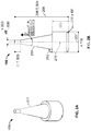
- FIG. 1 is a cross-sectional view of a thermostatic expansion valve according to an example embodiment of the present disclosure
- FIG. 2A is an orthogonal view of the metering pin of the thermostatic expansion valve illustrated in FIG. 1 ;
- FIG. 2B is a side view of the metering pin of the thermostatic expansion valve illustrated in FIG. 1 ;
- FIG. 3A is a side view of an example 1 ⁇ 5 ton metering pin for use in the thermostatic expansion valve illustrated in FIG. 1 ;
- FIG. 3B is a side view of an example 1 ⁇ 4 ton metering pin for use in the thermostatic expansion valve illustrated in FIG. 1 ;
- FIG. 3C is a side view of an example 1 ⁇ 2 ton metering pin for use in the thermostatic expansion valve illustrated in FIG. 1 .
- the refrigeration market is increasing demand for fractional tonnage expansion valves with balanced port construction.
- Current expansion valves do not offer a range of fractional tonnages with balanced port design.
- Some example embodiments disclosed herein utilize interchangeable valve elements to provide a range of fractional tonnage expansion valves with balanced port construction, while reducing the number of unique components for each fractional tonnage.
- Multiple metering pins may be interchangeable to provide different fractional refrigeration tonnages using the same thermostatic expansion valve.
- the different pins may have the same base diameter and overall length with a different taper portion on each pin (e.g., a different degree of taper, a different location of the start of the taper along the pin, etc.). Accordingly, fractional refrigeration tonnages of the thermostatic expansion valve may be changed during manufacturing and assembly at a factory, by a technician in the field, etc., simply by replacing only the appropriate metering pin without replacing other components of the valve, etc.
- each interchangeable metering pin may facilitate a balanced port for the thermostatic expansion valve (e.g., due to the taper portion or “shoulder” design of each metering pin, etc.).
- the normal projected area for each pin may be designed to equal an exposed area of the operating rod that the pin contacts at the tapered end. This may cancel out the forces due to pressure and facilitate balancing of the throttling port.
- Thermostatic expansion valves are commonly used for controlling the flow of liquid refrigerant into an evaporator, and are often designed to regulate refrigerant liquid flow into the evaporator in approximate proportion to evaporation of refrigerant liquid in the evaporator.
- Refrigerant gas leaving the evaporator is regulated by the thermostatic expansion valve responding to the temperature of the refrigerant gas leaving the evaporator and the pressure in the evaporator. This controlled flow inhibits the return of refrigerant liquid to the compressor, and the thermostatic expansion valve may control the flow of refrigerant by maintaining a predetermined superheat.
- An orifice in the thermostatic expansion valve meters the flow into the evaporator.
- the flow is modulated by a metering pin that varies the orifice opening.
- the metering pin may be subject to multiple forces, such as a power element pressure, an evaporator pressure, a superheat spring equivalent pressure, etc.
- a power assembly pressure corresponding to a saturation pressure of the refrigerant gas temperature leaving the evaporator may move the metering pin in an opening direction, while dosing forces are supplied by an evaporator pressure and a superheat spring.
- a vapor may be superheated whenever its temperature is higher than the saturation temperature corresponding to its pressure.
- the superheat equals the temperature increase above the saturation pressure at that temperature.
- the thermostatic expansion valve may control the superheat of the suction gas leaving the evaporator.
- the operating superheat of the thermostatic expansion valve may vary as the pressure drop across the thermostatic expansion valve ports changes due to changes in head pressure or suction pressure.
- the imbalance can sometimes result in compressor flooding or evaporation starvation.
- a balanced port attempts to reduce the effect of the pressure imbalance, to permit the thermostatic expansion valve to operate at a fairly constant superheat over a wide range of operating conditions.
- thermostatic expansion valves use a double ported design in which there are two paths for refrigerant flow. One path creates a force that tends to push the metering pin in the open direction, while the other path creates a force pushing the pin in the closed position. These paths are designed with the forces in each path equal to one another, to provide a balanced design.
- a metering pin includes a shoulder on the inlet side of the thermostatic expansion valve.
- the high inlet pressure times the area of the shoulder may result in an upward closing force, while the pressure differential across the pin results in a downward force.
- the shoulder By designing the shoulder carefully, the downward force may be balanced.
- FIG. 1 illustrates a thermostatic expansion valve 100 including an operating rod 102 , a recessed receiver portion 104 , and a first metering pin 106 .
- the first metering pin 106 is positioned at least partially within the recessed receiver portion 104 to selectively contact the operating rod 102 .
- the first metering pin 106 includes a base diameter 207 , an overall length 209 , and a taper portion 211 .
- the taper portion 211 is tapered at a specified degree 213 relative to a longitudinal axis 215 of the first metering pin 106 .
- FIG. 2B includes example dimensions for purposes of illustration only, and other embodiments may include any suitable dimensions for the metering pin 106 .
- the thermostatic expansion valve 100 is adapted to operate at a first specified refrigeration tonnage when the first metering pin 106 is positioned at least partially within the receiver portion 104 , and to operate at a second specified refrigeration tonnage when the first metering pin 106 is replaced with a second metering pin including a different taper portion than the first metering pin 106 .
- FIGS. 3A-3C illustrate three different metering pins 306 A, 306 B, and 306 C, each designed to operate the thermostatic expansion valve with a different specified refrigeration tonnage.
- FIG. 3A illustrates an example 1 ⁇ 5 ton metering pin 306 A
- FIG. 3B illustrates an example 1 ⁇ 4 ton metering pin 306 B
- FIG. 3C illustrates an example 1 ⁇ 2 ton metering pin 306 C.
- Each metering pin 306 A, 306 B and 306 C includes a different taper portion 311 A, 311 B, and 311 C, respectively.
- the angle 313 A, 313 B, and 313 C of each taper portion 311 A, 311 B, and 311 C is different, and an upper starting point of the taper portion 311 A, 311 B, and 311 C is different.
- FIGS. 3A-3C include example dimensions for purposes of illustration only, and other embodiments may include any suitable dimensions for the metering pins 306 A, 306 B and 306 C.
- the thermostatic expansion valve 100 would be adapted to operate at a first specified refrigeration tonnage of 1 ⁇ 5 ton when the metering pin 306 A is positioned at least partially within the receiver portion 104 , to operate at a second specified refrigeration tonnage of 1 ⁇ 4 ton when the metering pin 306 A is replaced with the metering pin 306 B, and to operate at a third specified refrigeration tonnage of 1 ⁇ 2 ton when the metering pin 306 A or 306 B is replaced with the metering pin 306 C.
- valve 100 may be adapted to receive metering pins for operating at refrigeration tonnages of 1/7 ton, 1 ⁇ 3 ton, or any other suitable tonnage, which may depend on a type of refrigerant used with the valve 100 .
- the refrigeration tonnage operation of the thermostatic expansion valve 100 may be changed during manufacturing and assembly at a factory, by a technician in the field, etc., simply by changing only the metering pin 106 , and leaving other components of the thermostatic expansion valve 100 in place.
- the thermostatic expansion valve 100 includes a seal 108 (e.g., an internal seal, etc.), a washer 109 , a spring carrier 110 , a buffer plate 112 , and a spring 114 .
- the metering pin 106 may be replaced with another metering pin for a different refrigeration tonnage (or a different metering pin may be selected for the initial expansion valve assembly at a factory, etc.), without changing the operating rod 102 , the seal 108 , the washer 109 , the spring carrier 110 , the buffer plate 112 , and the spring 114 , etc. Therefore, the operating rod 102 , the seal 108 , the washer 109 , the spring carrier 110 , the buffer plate 112 , the spring 114 , etc., may be common among different metering pins 106 for different refrigeration tonnages.
- the recessed receiver portion 104 may be common among different metering pins 106 . As shown in FIG. 1 , the recessed receiver portion 104 may be a port that is chamfered, drilled, etc., to receive different metering pins 106 .
- FIG. 1 also illustrates an optional pin guide 105 .
- the pin guide 105 sits on top of the spring 114 and holds the metering pin 106 in place.
- the pin guide 105 may be integral with the metering pin 106 , so the metering pin 106 and the pin guide 106 have a one piece construction.
- the thermostatic expansion valve 100 may include any suitable type of thermostatic expansion valve, such as a hermetic thermostatic expansion valve, etc.
- the metering pin 106 may be adapted to facilitate operation of the thermostatic expansion valve 100 with at least one of a minimum tonnage of 1/10 Ton for R-290 system refrigerant, a minimum tonnage of 1/14 Ton for R-404A or R-1234yf system refrigerants, etc.
- At least one of the operating rod 102 , the recessed receiver portion 104 , and the metering pin 106 may comprise stainless steel, or any other suitable material for controlling flow of refrigerant.
- the thermostatic expansion valve 100 may include a check valve to inhibit refrigerant from flowing in a reverse direction through the thermostatic expansion valve 100 .
- the thermostatic expansion valve includes an inlet port 116 for receiving refrigerant, and an outlet port 118 for supplying refrigerant.
- the metering pin 106 is located in a refrigerant flow path between the inlet port 116 and the outlet port 118 .
- the base diameter 207 , overall length 209 , and specified degree 213 of the taper portion relative to the longitudinal axis 215 of the metering pin 106 may facilitate a balanced port where an inlet pressure times an area of the taper portion 211 of the metering pin 106 results in an upward closing force on the valve that is balanced with a downward force according to a pressure differential across the metering pin 106 .
- a normal projection area of the metering pin 106 on the operating rod 102 at a tapered end 120 of the metering pin 106 may be equal to an exposed area of the operating rod 102 to balance the effects of inlet pressure on the thermostatic expansion valve 100 .
- the net force up or down on the operating rod 102 and metering pin 106 may be substantially balanced.
- an imbalance force that would otherwise bias the operating rod 102 and metering pin 106 may be reduced (e.g., eliminated), to provide better control over a wider range of evaporator loads.
- the valve may be substantially balanced within a suitable tolerance range, which may include an upward closing force on the valve (e.g., an inlet pressure times an area of the taper portion 211 of the metering pin 106 ), is within about 1% of a downward opening force, within about 2% of the downward force, within about 5% of the downward force, etc.
- the thermostatic expansion valve 100 may be used in any refrigeration system, such as a free-standing refrigerator, a milk cooler, a food service preparation table, a refrigerated drawer, an under-counter refrigerator, a walk-in refrigerator, a roll-in refrigerator, etc.
- the thermostatic expansion valve 100 may be used in a cooling system such as ice production equipment, ice storage equipment, a freezer, a storage cooler, a soft serve ice cream machine, a compressor, a condenser, an evaporator, a water filter, a slush and/or smoothie machine, a blast chiller, a blast freezer, a drop-in pan chiller, an ice cream cabinet, an air conditioner, a heat pump, etc.
- a cooling system such as ice production equipment, ice storage equipment, a freezer, a storage cooler, a soft serve ice cream machine, a compressor, a condenser, an evaporator, a water filter, a slush and/or smoothie machine, a blast chiller, a blast freezer, a drop-in pan chiller, an ice cream cabinet, an air conditioner, a heat pump, etc.
- a thermostatic expansion valve includes an operating rod, a recessed receiver portion, and a metering pin positioned at least partially within the recessed receiver portion to selectively contact the operating rod.
- the metering pin includes a base diameter, an overall length, and a taper portion.
- the taper portion is tapered at a specified degree relative to a longitudinal axis of the metering pin.
- a normal projection area of the metering pin on the operating rod at a tapered end of the metering pin is equal to an exposed area of the operating rod to balance the effects of pressure on the thermostatic expansion valve.
- the base diameter, overall length, and specified degree of the taper portion relative to the longitudinal axis of the metering pin may facilitate a balanced port where an inlet pressure times an area of the taper portion of the first metering pin results in an upward closing force on the valve that is balanced with a downward force according to a pressure differential across the metering pin.
- a method of replacing a metering pin in a thermostatic expansion valve includes an operating rod and a recessed receiver portion.
- the method includes inserting a first metering pin at least partially within the receiver portion to selectively contact the operating rod to operate the thermostatic expansion valve at a first specified refrigeration tonnage.
- the first metering pin includes a base diameter, an overall length, and a taper portion. The taper portion is tapered at a specified degree relative to a longitudinal axis of the first metering pin.
- the method also includes removing the first metering pin from the receiver portion, and inserting a second metering pin at least partially within the receiver portion to selectively contact the operating rod to operate the thermostatic valve at a second specified refrigeration tonnage, wherein the second metering pin includes a different taper portion than the first metering pin.
- the base diameter, overall length, and specified degree of the taper portion relative to the longitudinal axis of the first metering pin may facilitate a balanced port where an inlet pressure times an area of the taper portion of the first metering pin results in an upward closing force on the valve that is balanced with a downward force according to a pressure differential across the first metering pin.
- a base diameter, an overall length, and a specified degree of the taper portion relative to a longitudinal axis of the second metering pin may facilitate a balanced port where the inlet pressure times an area of the taper portion of the second metering pin results in the upward closing force on the valve that is balanced with the downward force according to the pressure differential across the second metering pin.
- the thermostatic expansion valve may include at least one of a common seal, a common push rod, a common spring carrier, a common buffer plate, and a common spring. And, removing the first metering pin and inserting the second metering pin may include removing the first metering pin and inserting the second metering pin without changing the at least one of the common seal, the common spring carrier, the common buffer plate, and the common spring.
- the method further includes removing the second metering pin from the receiver portion, and inserting a third metering pin at least partially within the receiver portion to selectively contact the operating rod to operate the thermostatic valve at a third specified refrigeration tonnage, wherein the third metering pin includes a different taper portion than the first metering pin and the second metering pin.
- the first metering pin may be a 1 ⁇ 5 ton metering pin
- the second metering pin comprises a 1 ⁇ 4 ton metering pin
- the third metering pin comprises a 1 ⁇ 2 ton metering pin. Accordingly, fractional refrigeration tonnages of the thermostatic expansion valve may be selected, changed, etc., simply by inserting the appropriate metering pin, without replacing other components of the valve, while replacing only a minimal (or at least reduced) number of other components of the valve, etc.
- each interchangeable metering pin may facilitate a balanced port for the thermostatic expansion valve (e.g., due to the taper portion or “shoulder” design of each metering pin, etc.).
- Example embodiments are provided so that this disclosure will be thorough, and will fully convey the scope to those who are skilled in the art. Numerous specific details are set forth such as examples of specific components, devices, and methods, to provide a thorough understanding of embodiments of the present disclosure. It will be apparent to those skilled in the art that specific details need not be employed, that example embodiments may be embodied in many different forms, and that neither should be construed to limit the scope of the disclosure. In some example embodiments, well-known processes, well-known device structures, and well-known technologies are not described in detail.
- parameter X may have a range of values from about A to about Z.
- disclosure of two or more ranges of values for a parameter subsume all possible combination of ranges for the value that might be claimed using endpoints of the disclosed ranges.
- parameter X is exemplified herein to have values in the range of 1-10, or 2-9, or 3-8, it is also envisioned that Parameter X may have other ranges of values including 1-9, 1-8, 1-3, 1-2, 2-10, 2-8, 2-3, 3-10, and 3-9.
- first, second, third, etc. may be used herein to describe various elements, components, regions, layers and/or sections, these elements, components, regions, layers and/or sections should not be limited by these terms. These terms may be only used to distinguish one element, component, region, layer or section from another region, layer or section. Terms such as “first,” “second,” and other numerical terms when used herein do not imply a sequence or order unless clearly indicated by the context. Thus, a first element, component, region, layer or section discussed below could be termed a second element, component, region, layer or section without departing from the teachings of the example embodiments.
- Spatially relative terms such as “inner,” “outer,” “beneath,” “below,” “lower,” “above,” “upper” and the like, may be used herein for ease of description to describe one element or feature's relationship to another element(s) or feature(s) as illustrated in the figures. Spatially relative terms may be intended to encompass different orientations of the device in use or operation in addition to the orientation depicted in the figures. For example, if the device in the figures is turned over, elements described as “below” or “beneath” other elements or features would then be oriented “above” the other elements or features. Thus, the example term “below” can encompass both an orientation of above and below. The device may be otherwise oriented (rotated 90 degrees or at other orientations) and the spatially relative descriptors used herein interpreted accordingly.
Landscapes
- Engineering & Computer Science (AREA)
- Physics & Mathematics (AREA)
- Mechanical Engineering (AREA)
- Thermal Sciences (AREA)
- General Engineering & Computer Science (AREA)
- Temperature-Responsive Valves (AREA)
- Fluid Mechanics (AREA)
Abstract
Description
Claims (20)
Priority Applications (1)
| Application Number | Priority Date | Filing Date | Title |
|---|---|---|---|
| US16/704,749 US11137182B2 (en) | 2019-11-21 | 2019-12-05 | Thermostatic expansion valves including interchangeable metering pins |
Applications Claiming Priority (2)
| Application Number | Priority Date | Filing Date | Title |
|---|---|---|---|
| US201962938714P | 2019-11-21 | 2019-11-21 | |
| US16/704,749 US11137182B2 (en) | 2019-11-21 | 2019-12-05 | Thermostatic expansion valves including interchangeable metering pins |
Publications (2)
| Publication Number | Publication Date |
|---|---|
| US20210156599A1 US20210156599A1 (en) | 2021-05-27 |
| US11137182B2 true US11137182B2 (en) | 2021-10-05 |
Family
ID=75973794
Family Applications (1)
| Application Number | Title | Priority Date | Filing Date |
|---|---|---|---|
| US16/704,749 Active 2040-05-24 US11137182B2 (en) | 2019-11-21 | 2019-12-05 | Thermostatic expansion valves including interchangeable metering pins |
Country Status (1)
| Country | Link |
|---|---|
| US (1) | US11137182B2 (en) |
Families Citing this family (2)
| Publication number | Priority date | Publication date | Assignee | Title |
|---|---|---|---|---|
| US11879676B2 (en) | 2021-07-30 | 2024-01-23 | Danfoss A/S | Thermal expansion valve for a heat exchanger and heat exchanger with a thermal expansion valve |
| US20230034594A1 (en) * | 2021-07-30 | 2023-02-02 | Danfoss A/S | Thermal expansion valve for a residential refrigeration application |
Citations (20)
| Publication number | Priority date | Publication date | Assignee | Title |
|---|---|---|---|---|
| US2550022A (en) * | 1947-06-04 | 1951-04-24 | Gen Controls Co | Expansion valve |
| US2966044A (en) * | 1956-12-21 | 1960-12-27 | Mitchell Co John E | Regulator for flow-responsive refrigeration valve |
| US3317135A (en) * | 1963-09-17 | 1967-05-02 | Feinberg Maurice | Electrically controlled thermosensitive actuators for remote control of valves and other devices |
| US4095742A (en) | 1976-08-26 | 1978-06-20 | Virginia Chemicals Inc. | Balanced single port thermostatic expansion valve |
| US4341090A (en) * | 1981-01-26 | 1982-07-27 | Lennox Industries, Inc. | Variable orifice metering |
| US4475686A (en) * | 1977-11-03 | 1984-10-09 | Danfoss A/S | Valve for liquid injection into a refrigerant evaporator |
| US4523436A (en) * | 1983-12-22 | 1985-06-18 | Carrier Corporation | Incrementally adjustable electronic expansion valve |
| US5002089A (en) * | 1990-04-02 | 1991-03-26 | Carrier Corporation | Variable area refrigerant expansion device for heating mode of a heat pump |
| US5026022A (en) * | 1990-08-28 | 1991-06-25 | Parker Hannifin Corporation | Thermostatic expansion valve for low refrigerant flow rates |
| US5832744A (en) * | 1996-09-16 | 1998-11-10 | Sporlan Valve Company | Distributor for refrigeration system |
| US6161766A (en) * | 1999-09-07 | 2000-12-19 | Goba; Stephen M. | Refrigeration expansion valve having a port to which a pressure-measuring device may be connected |
| US20080087038A1 (en) * | 2004-10-21 | 2008-04-17 | Danfoss A/S | Valve For Use In A Refrigeration System |
| US20090045264A1 (en) * | 2007-08-17 | 2009-02-19 | Zheng Lou | Thermostatic expansion valve |
| US7707844B2 (en) | 2006-02-17 | 2010-05-04 | Emerson Electric Co. | Thermostatic expansion valve with bypass passage |
| US20160097465A1 (en) * | 2014-10-01 | 2016-04-07 | Emerson Electric Co. | Closures Including Adjustment Tools for Adjustment Mechanisms |
| US9631850B2 (en) * | 2012-04-28 | 2017-04-25 | Zhejiang Sanhua Co., Ltd. | Thermal expansion valve with one-way control function |
| US20170219277A1 (en) * | 2016-01-29 | 2017-08-03 | Samsung Electronics Co., Ltd | Refrigerator and method of controlling the same |
| US9810460B2 (en) * | 2011-10-19 | 2017-11-07 | Trane International Inc. | Reversible flow electric expansion valve |
| US20180142802A1 (en) * | 2015-04-09 | 2018-05-24 | Taconova Group AG | Valve For Use In the Feed Pipe Or Return Pipe Of A Heating or Cooling Water Circuit |
| US10295064B2 (en) * | 2014-03-19 | 2019-05-21 | Zhejiang Sanhua Co., Ltd | Electronic expansion valve |
-
2019
- 2019-12-05 US US16/704,749 patent/US11137182B2/en active Active
Patent Citations (20)
| Publication number | Priority date | Publication date | Assignee | Title |
|---|---|---|---|---|
| US2550022A (en) * | 1947-06-04 | 1951-04-24 | Gen Controls Co | Expansion valve |
| US2966044A (en) * | 1956-12-21 | 1960-12-27 | Mitchell Co John E | Regulator for flow-responsive refrigeration valve |
| US3317135A (en) * | 1963-09-17 | 1967-05-02 | Feinberg Maurice | Electrically controlled thermosensitive actuators for remote control of valves and other devices |
| US4095742A (en) | 1976-08-26 | 1978-06-20 | Virginia Chemicals Inc. | Balanced single port thermostatic expansion valve |
| US4475686A (en) * | 1977-11-03 | 1984-10-09 | Danfoss A/S | Valve for liquid injection into a refrigerant evaporator |
| US4341090A (en) * | 1981-01-26 | 1982-07-27 | Lennox Industries, Inc. | Variable orifice metering |
| US4523436A (en) * | 1983-12-22 | 1985-06-18 | Carrier Corporation | Incrementally adjustable electronic expansion valve |
| US5002089A (en) * | 1990-04-02 | 1991-03-26 | Carrier Corporation | Variable area refrigerant expansion device for heating mode of a heat pump |
| US5026022A (en) * | 1990-08-28 | 1991-06-25 | Parker Hannifin Corporation | Thermostatic expansion valve for low refrigerant flow rates |
| US5832744A (en) * | 1996-09-16 | 1998-11-10 | Sporlan Valve Company | Distributor for refrigeration system |
| US6161766A (en) * | 1999-09-07 | 2000-12-19 | Goba; Stephen M. | Refrigeration expansion valve having a port to which a pressure-measuring device may be connected |
| US20080087038A1 (en) * | 2004-10-21 | 2008-04-17 | Danfoss A/S | Valve For Use In A Refrigeration System |
| US7707844B2 (en) | 2006-02-17 | 2010-05-04 | Emerson Electric Co. | Thermostatic expansion valve with bypass passage |
| US20090045264A1 (en) * | 2007-08-17 | 2009-02-19 | Zheng Lou | Thermostatic expansion valve |
| US9810460B2 (en) * | 2011-10-19 | 2017-11-07 | Trane International Inc. | Reversible flow electric expansion valve |
| US9631850B2 (en) * | 2012-04-28 | 2017-04-25 | Zhejiang Sanhua Co., Ltd. | Thermal expansion valve with one-way control function |
| US10295064B2 (en) * | 2014-03-19 | 2019-05-21 | Zhejiang Sanhua Co., Ltd | Electronic expansion valve |
| US20160097465A1 (en) * | 2014-10-01 | 2016-04-07 | Emerson Electric Co. | Closures Including Adjustment Tools for Adjustment Mechanisms |
| US20180142802A1 (en) * | 2015-04-09 | 2018-05-24 | Taconova Group AG | Valve For Use In the Feed Pipe Or Return Pipe Of A Heating or Cooling Water Circuit |
| US20170219277A1 (en) * | 2016-01-29 | 2017-08-03 | Samsung Electronics Co., Ltd | Refrigerator and method of controlling the same |
Also Published As
| Publication number | Publication date |
|---|---|
| US20210156599A1 (en) | 2021-05-27 |
Similar Documents
| Publication | Publication Date | Title |
|---|---|---|
| JP6785988B2 (en) | Air conditioner | |
| US20230112193A1 (en) | Refrigeration System with Efficient Expansion Device Control, Liquid Refrigerant Return, Oil Return, and Evaporator Defrost | |
| US8205465B2 (en) | Control system for an expansion valve regulating refrigerant to an evaporator of a climate control system | |
| EP2375188B1 (en) | Air conditioner | |
| US6418741B1 (en) | Expansion/check valve assembly including a reverse flow rate adjustment device | |
| US20140083126A1 (en) | Air-conditioning apparatus | |
| US11137182B2 (en) | Thermostatic expansion valves including interchangeable metering pins | |
| EP2868997B1 (en) | Refrigerator | |
| CN204512473U (en) | Refrigeration agent throttling arrangement and aircondition | |
| WO2010013392A1 (en) | Refrigerating device | |
| CA2389695C (en) | Vapor compression system and method for controlling conditions in ambient surroundings | |
| WO2018121425A1 (en) | Refrigeration system utilizing parallel and serial-connected dual evaporators, and control method thereof | |
| KR19980013707A (en) | A refrigerating machine | |
| US10415859B2 (en) | Heat recovery system with liquid separator application | |
| EP1783443A1 (en) | Freezing apparatus | |
| NZ524732A (en) | Expansion device for vapor compression system with variable orifice expansion device | |
| AU2001291017A1 (en) | Expansion device for vapor compression system | |
| CN101852503A (en) | A multi-temperature refrigerator | |
| WO2011074028A1 (en) | Air conditioner | |
| US6857281B2 (en) | Expansion device for vapor compression system | |
| US10823479B2 (en) | Multi-evaporator appliance having a multi-directional valve for delivering refrigerant to the evaporators | |
| JP5770157B2 (en) | Refrigeration equipment | |
| JP6695447B2 (en) | Flow path switching device, refrigeration cycle circuit and refrigerator | |
| GB2581720A (en) | Refrigeration Apparatus and Outdoor unit | |
| JP2006234207A (en) | Refrigerating cycle decompressor |
Legal Events
| Date | Code | Title | Description |
|---|---|---|---|
| FEPP | Fee payment procedure |
Free format text: ENTITY STATUS SET TO UNDISCOUNTED (ORIGINAL EVENT CODE: BIG.); ENTITY STATUS OF PATENT OWNER: LARGE ENTITY |
|
| AS | Assignment |
Owner name: EMERSON ELECTRIC CO., MISSOURI Free format text: ASSIGNMENT OF ASSIGNORS INTEREST;ASSIGNORS:HESCHEL, SUSAN M.;STRAZAR, KYLE A.;SCHROEDER, CHRISTOPHER J.;SIGNING DATES FROM 20191122 TO 20191126;REEL/FRAME:051198/0299 |
|
| STPP | Information on status: patent application and granting procedure in general |
Free format text: NON FINAL ACTION MAILED |
|
| STPP | Information on status: patent application and granting procedure in general |
Free format text: RESPONSE TO NON-FINAL OFFICE ACTION ENTERED AND FORWARDED TO EXAMINER |
|
| STPP | Information on status: patent application and granting procedure in general |
Free format text: PUBLICATIONS -- ISSUE FEE PAYMENT RECEIVED |
|
| STPP | Information on status: patent application and granting procedure in general |
Free format text: PUBLICATIONS -- ISSUE FEE PAYMENT VERIFIED |
|
| STCF | Information on status: patent grant |
Free format text: PATENTED CASE |
|
| AS | Assignment |
Owner name: COPELAND COMFORT CONTROL LP, MISSOURI Free format text: SUPPLEMENTAL IP ASSIGNMENT AGREEMENT;ASSIGNOR:EMERSON ELECTRIC CO.;REEL/FRAME:063804/0611 Effective date: 20230426 |
|
| AS | Assignment |
Owner name: ROYAL BANK OF CANADA, AS COLLATERAL AGENT, CANADA Free format text: SECURITY INTEREST;ASSIGNOR:COPELAND COMFORT CONTROL LP;REEL/FRAME:064278/0165 Effective date: 20230531 Owner name: U.S. BANK TRUST COMPANY, NATIONAL ASSOCIATION, AS NOTES COLLATERAL AGENT, MINNESOTA Free format text: SECURITY INTEREST;ASSIGNOR:COPELAND COMFORT CONTROL LP;REEL/FRAME:064280/0333 Effective date: 20230531 Owner name: WELLS FARGO BANK, NATIONAL ASSOCIATION, AS COLLATERAL AGENT, CALIFORNIA Free format text: SECURITY INTEREST;ASSIGNOR:COPELAND COMFORT CONTROL LP;REEL/FRAME:064286/0001 Effective date: 20230531 |
|
| AS | Assignment |
Owner name: U.S. BANK TRUST COMPANY, NATIONAL ASSOCIATION, AS NOTES COLLATERAL AGENT, MINNESOTA Free format text: SECURITY INTEREST;ASSIGNOR:COPELAND COMFORT CONTROL LP;REEL/FRAME:068255/0466 Effective date: 20240708 |
|
| MAFP | Maintenance fee payment |
Free format text: PAYMENT OF MAINTENANCE FEE, 4TH YEAR, LARGE ENTITY (ORIGINAL EVENT CODE: M1551); ENTITY STATUS OF PATENT OWNER: LARGE ENTITY Year of fee payment: 4 |