US11137016B2 - Washer with shear tube - Google Patents
Washer with shear tube Download PDFInfo
- Publication number
- US11137016B2 US11137016B2 US16/378,433 US201916378433A US11137016B2 US 11137016 B2 US11137016 B2 US 11137016B2 US 201916378433 A US201916378433 A US 201916378433A US 11137016 B2 US11137016 B2 US 11137016B2
- Authority
- US
- United States
- Prior art keywords
- washer
- central body
- connection
- fastener
- passage
- Prior art date
- Legal status (The legal status is an assumption and is not a legal conclusion. Google has not performed a legal analysis and makes no representation as to the accuracy of the status listed.)
- Active
Links
- 238000004873 anchoring Methods 0.000 claims description 35
- 239000002023 wood Substances 0.000 description 4
- 238000007789 sealing Methods 0.000 description 3
- 235000013290 Sagittaria latifolia Nutrition 0.000 description 2
- 235000015246 common arrowhead Nutrition 0.000 description 2
- 230000002093 peripheral effect Effects 0.000 description 2
- 229910000831 Steel Inorganic materials 0.000 description 1
- 229920002522 Wood fibre Polymers 0.000 description 1
- 238000005553 drilling Methods 0.000 description 1
- 230000000694 effects Effects 0.000 description 1
- 239000000463 material Substances 0.000 description 1
- 239000010959 steel Substances 0.000 description 1
- 239000002025 wood fiber Substances 0.000 description 1
Images


Classifications
-
- F—MECHANICAL ENGINEERING; LIGHTING; HEATING; WEAPONS; BLASTING
- F16—ENGINEERING ELEMENTS AND UNITS; GENERAL MEASURES FOR PRODUCING AND MAINTAINING EFFECTIVE FUNCTIONING OF MACHINES OR INSTALLATIONS; THERMAL INSULATION IN GENERAL
- F16B—DEVICES FOR FASTENING OR SECURING CONSTRUCTIONAL ELEMENTS OR MACHINE PARTS TOGETHER, e.g. NAILS, BOLTS, CIRCLIPS, CLAMPS, CLIPS OR WEDGES; JOINTS OR JOINTING
- F16B43/00—Washers or equivalent devices; Other devices for supporting bolt-heads or nuts
-
- E—FIXED CONSTRUCTIONS
- E04—BUILDING
- E04B—GENERAL BUILDING CONSTRUCTIONS; WALLS, e.g. PARTITIONS; ROOFS; FLOORS; CEILINGS; INSULATION OR OTHER PROTECTION OF BUILDINGS
- E04B1/00—Constructions in general; Structures which are not restricted either to walls, e.g. partitions, or floors or ceilings or roofs
- E04B1/18—Structures comprising elongated load-supporting parts, e.g. columns, girders, skeletons
- E04B1/24—Structures comprising elongated load-supporting parts, e.g. columns, girders, skeletons the supporting parts consisting of metal
- E04B1/2403—Connection details of the elongated load-supporting parts
-
- E—FIXED CONSTRUCTIONS
- E04—BUILDING
- E04B—GENERAL BUILDING CONSTRUCTIONS; WALLS, e.g. PARTITIONS; ROOFS; FLOORS; CEILINGS; INSULATION OR OTHER PROTECTION OF BUILDINGS
- E04B1/00—Constructions in general; Structures which are not restricted either to walls, e.g. partitions, or floors or ceilings or roofs
- E04B1/18—Structures comprising elongated load-supporting parts, e.g. columns, girders, skeletons
- E04B1/26—Structures comprising elongated load-supporting parts, e.g. columns, girders, skeletons the supporting parts consisting of wood
- E04B1/2604—Connections specially adapted therefor
- E04B1/2608—Connectors made from folded sheet metal
-
- F—MECHANICAL ENGINEERING; LIGHTING; HEATING; WEAPONS; BLASTING
- F16—ENGINEERING ELEMENTS AND UNITS; GENERAL MEASURES FOR PRODUCING AND MAINTAINING EFFECTIVE FUNCTIONING OF MACHINES OR INSTALLATIONS; THERMAL INSULATION IN GENERAL
- F16B—DEVICES FOR FASTENING OR SECURING CONSTRUCTIONAL ELEMENTS OR MACHINE PARTS TOGETHER, e.g. NAILS, BOLTS, CIRCLIPS, CLAMPS, CLIPS OR WEDGES; JOINTS OR JOINTING
- F16B35/00—Screw-bolts; Stay-bolts; Screw-threaded studs; Screws; Set screws
-
- F—MECHANICAL ENGINEERING; LIGHTING; HEATING; WEAPONS; BLASTING
- F16—ENGINEERING ELEMENTS AND UNITS; GENERAL MEASURES FOR PRODUCING AND MAINTAINING EFFECTIVE FUNCTIONING OF MACHINES OR INSTALLATIONS; THERMAL INSULATION IN GENERAL
- F16B—DEVICES FOR FASTENING OR SECURING CONSTRUCTIONAL ELEMENTS OR MACHINE PARTS TOGETHER, e.g. NAILS, BOLTS, CIRCLIPS, CLAMPS, CLIPS OR WEDGES; JOINTS OR JOINTING
- F16B5/00—Joining sheets or plates, e.g. panels, to one another or to strips or bars parallel to them
- F16B5/02—Joining sheets or plates, e.g. panels, to one another or to strips or bars parallel to them by means of fastening members using screw-thread
-
- E—FIXED CONSTRUCTIONS
- E04—BUILDING
- E04B—GENERAL BUILDING CONSTRUCTIONS; WALLS, e.g. PARTITIONS; ROOFS; FLOORS; CEILINGS; INSULATION OR OTHER PROTECTION OF BUILDINGS
- E04B1/00—Constructions in general; Structures which are not restricted either to walls, e.g. partitions, or floors or ceilings or roofs
- E04B1/18—Structures comprising elongated load-supporting parts, e.g. columns, girders, skeletons
- E04B1/26—Structures comprising elongated load-supporting parts, e.g. columns, girders, skeletons the supporting parts consisting of wood
- E04B1/2604—Connections specially adapted therefor
- E04B2001/2644—Brackets, gussets or joining plates
-
- E—FIXED CONSTRUCTIONS
- E04—BUILDING
- E04B—GENERAL BUILDING CONSTRUCTIONS; WALLS, e.g. PARTITIONS; ROOFS; FLOORS; CEILINGS; INSULATION OR OTHER PROTECTION OF BUILDINGS
- E04B1/00—Constructions in general; Structures which are not restricted either to walls, e.g. partitions, or floors or ceilings or roofs
- E04B1/18—Structures comprising elongated load-supporting parts, e.g. columns, girders, skeletons
- E04B1/26—Structures comprising elongated load-supporting parts, e.g. columns, girders, skeletons the supporting parts consisting of wood
- E04B1/2604—Connections specially adapted therefor
- E04B2001/268—Connection to foundations
- E04B2001/2684—Connection to foundations with metal connectors
Definitions
- the present invention relates to an improved fastener system for attaching a connector or other upper member to a lower structural member such as a post or beam
- the improved fastener consists of a fastener having an extending shank that is driven into a lower structural member and the fastener is received by a washer that also has an extending tube, and the extending tube of the washer is received by the connector or upper member and is also, preferably received in the structural member.
- U.S. Pat. No. 2,111,110 granted to A. J. Deniston, Jr., et al, on Apr. 21, 1937, teaches using an enlarged sealing head or washer with a nail or screw to secure sheathing and similar members to a roof or similar structure.
- the fastener used is formed with a special, enlarged shank portion, or alternatively an annular groove or series of notches, below the head of the fastener which is designed to resist pull-out of the fastener.
- the sealing head is made from lead or a softer material than the fastener head and is formed with a narrowing, depending shank that extends to the enlarged shank portion and closely receives the upper portion of the shank of the fastener. The sealing head is deformed by the driving of the nail or screw and helps seal the opening in the sheathing.
- U.S. Pat. No. 3,305,987 granted to Floyd E. Weaver, et al, on Feb. 28, 1967, teaches using an enlarged, shear washer with an anchored bolt to secure together two structural members in a building.
- the shear washer is formed with an annular outer depending flange or load-supporting portion at is periphery that has cutting flutes or grooves and teeth that allow it to cut into one of the structural members.
- the shear washer is either threaded onto the bolt, itself, or the shear washer is driven into wooden structural member by the operation of threading a standard nut onto the bolt that is keyed with the shear washer.
- the shear washer improves the strength of the connection.
- U.S. Pat. No. 5,201,627 granted to Marita Biedenbach on Apr. 13, 1993, teaches using a ring-shaped washer with a self-drilling, wood screw.
- the ring-shaped washer has a pair of downwardly depending annular edges that are pushed into the wood member when the screw is driven. These depending edges are disposed parallel to the shank of the fastener.
- the ring-shaped washer prevents over-driving of the fastener and helps to prevent the wood from splitting.
- the ring-shaped washer translates forces from the screw to the structural member at right angles to shank of the screw. Also according to Biedenbach, this redirection of forces reduces wedge effects and reduces the likelihood of splitting of the structural member.
- U.S. Pat. No. 8,544,291 granted to Jean-Nicolas Guyomard on Jun. 4, 2013, teaches a washer with protruding elements used with a screw to better anchor an “element” such as a headlight to a “holder” such as the front face of a vehicle.
- the protruding elements of the washer are located on the peripheral edge and the internal edge of the opening in the washer to connect to both the “element” and the “holder”.
- US Patent Publication 2013/0336743A1 applied for by Ian A. Hill, and published Dec. 19, 2013, teaches a fastener that is used with a decorative washer.
- the head of the fastener and the decorative washer are shaped to give the appearance that the fastener and washer are a one-piece, headed bolt, giving the connection a particular aesthetic.
- the prior art inventions teach washers that either deform while being installed to help seal the connection or they have teeth, protruding members or are otherwise formed to positively engage with and/or deform the upper element or member in the connection.
- the present invention provides a shear washer that is installed as quickly and in the same manner as a standard washer, yet provides improved fastener shear resistance.
- the present invention provides a shear washer that is not designed to deform, nor does it deform or bite into the upper member or connector, although the shear tube of the shear washer can engage the opening in the connector or upper member that also receives the fastener.
- the present invention provides a shear washer that engages with the lower or anchoring structural member into which the fastener is driven.
- a connection is provided between an anchoring structural member and an upper member with the anchoring structural member having an upper surface, and the upper member or connector having an upper surface and a lower surface.
- the lower surface of the upper member interfaces with the upper surface of the anchoring structural member.
- the upper member has a passage between the upper surface and the lower surface.
- the connection includes a fastener and a washer.
- the washer has a central body with a passage there through, a top surface and a bottom surface.
- the washer is formed with an extending tube that extends from the central body toward the anchoring structural member and past the bottom surface of the central body.
- the bottom surface of the central body interfaces with the upper surface of the upper member without deforming the upper surface of the upper member.
- the central body also has a bearing surface opposed to the bottom surface of the central body.
- the extending tube has a passage that communicates with the passage through the central body.
- the extending tube of the washer is received by the passage of the upper member without deforming the passage of the upper member.
- the fastener has a head and an extending shank. The extending shank of the fastener is received in the anchoring structural member and passes through the passage in the upper member and the passage in the extending tube and the passage in the central body of the washer.
- the head of the fastener has an underside that interfaces with the bearing surface of the central body of the washer.
- the extending tube can be formed with a cutting edge.
- the extending shank of the fastener makes contact with the passage of the extending tube.
- the fastener is preferably a screw.
- FIG. 1 is a perspective view of a connection made according to the present invention.
- FIG. 2 is an exploded, perspective view of a connection made according to the present invention shown in FIG. 1 .
- FIG. 3 is a sectional, side view of the connection shown in FIG. 1 .
- FIG. 4 is an upper perspective view of one embodiment of the separate washer that forms part of the connection of the present invention.
- FIG. 5 is a lower perspective view of the separate washer that forms part of the connection of the present invention.
- FIG. 6 is an exploded view of the separate screw and separate washer with a dotted line and arrow head showing how the separate screw is inserted into the washer.
- FIG. 7 is an upper perspective view of the separate screw partially inserted into the separate washer
- FIG. 8 is an upper perspective view of the screw inserted fully into the washer of the present invention.
- FIG. 9 is a top view of the separate washer that forms part of the present invention.
- FIG. 10 is a bottom view of the separate washer that forms part of the present invention.
- FIG. 11 is a front view of the separate washer that forms part of the present invention.
- FIG. 12 is a side view of the separate washer that forms part of the present invention.
- FIG. 13 is a top view of the screw shown fully inserted into one washer of the present invention as shown in FIG. 8 .
- FIG. 14 is a bottom view of the screw shown fully inserted into one washer of the present invention.
- FIG. 15 is a front view of the embodiment shown in FIGS. 8, 13 and 14 .
- FIG. 16 is a side view of the embodiment shown in FIGS. 8, 13 14 , and 15 .
- FIG. 17 is a sectional, side view of the connection similar to that shown in FIG. 1 , except the screws have been installed slightly askew.
- FIG. 18 is a perspective view of a connection made according to the present invention, showing an alternate washer embodiment.
- FIG. 19 is an exploded, perspective view of a connection made according to the present invention shown in FIG. 18 .
- FIG. 20 is a sectional, side view of the connection shown in FIG. 18 .
- FIG. 21 is an upper perspective view of an alternate embodiment of the separate washer that forms part of the connection of the present invention.
- FIG. 22 is a lower perspective view of the separate washer of FIG. 21 that forms part of the connection of the present invention.
- FIG. 23 is an exploded view of the separate screw and separate washer of FIG. 21 with a dotted line and arrow head showing how the separate screw is inserted into the washer.
- FIG. 24 is an upper perspective view of the separate screw partially inserted into the separate washer
- FIG. 25 is an upper perspective view of the screw inserted fully into the washer of FIG. 21 of the present invention.
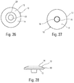
- FIG. 26 is a top view of the separate washer of FIG. 21 that forms part of the present invention.
- FIG. 27 is a bottom view of the separate washer of FIG. 21 that forms part of the present invention.
- FIG. 28 is a side view of the separate washer of FIG. 21 that forms part of the present invention.
- FIG. 29 is a top view of the screw shown fully inserted into one washer of the present invention as shown in FIG. 25 .
- FIG. 30 is a bottom view of the screw shown fully inserted into one washer of the present invention.
- FIG. 31 is a side view of the embodiment shown in FIGS. 25, 29 and 30 .
- FIG. 32 is a perspective view of an alternate connection made according to the present invention.
- FIG. 33 is a perspective view of an alternate connection made according to the present invention.
- FIG. 34 is a perspective view of an alternate connection made according to the present invention.
- FIG. 35 is a perspective view of an alternate connection made according to the present invention.
- FIG. 36 is a perspective view of an alternate connection made according to the present invention.
- FIG. 37 is a perspective view of an alternate connection made according to the present invention.
- FIG. 38 is a top view of the screw shown fully inserted into one washer of the present invention.
- FIG. 39 is a sectional, side view of the connection.
- the fastener 1 attaches a connector or anchored member 3 to an anchoring structural member 4 .
- the connector 3 attaches to two different anchoring structural members 4 , a post 4 a and a beam 4 b .
- the fastener 1 attaches a connector or upper member 3 to the anchoring structural member 4 by means of an extending shank 9 .
- the anchoring structural member 4 has an upper surface 5 .
- the upper member or connector 3 has an upper surface 7 and a lower surface 8 .
- the lower surface 8 of the upper member 3 interfaces with the upper surface 5 of the anchoring structural member 4 .
- the upper member 3 has a passage 6 between the upper surface 7 and the lower surface 8 .
- the passage 6 can be a notch in the upper member 3 or, as shown in FIG. 2 , an opening through upper member 3 with a closed peripheral edge.
- the washer 10 of the present invention has a central body 12 with a passage 13 there through, a top surface 14 and a bottom surface 15 .
- the central body 12 of washer 10 can be preferably shaped to resemble a typical hexagonal nut or bolt head with a circular, laterally extending washer beneath the nut.
- the washer 10 is formed with an extending tube 16 that extends from the central body 12 toward, and preferably, into the anchoring structural member 4 .
- the extending tube 16 can be formed with a cutting edge 17 .
- the extending tube 16 of washer 10 is driven into the lower or anchoring structural member 4 by fastener 1 , which is preferably a screw.
- fastener 1 which is preferably a screw.
- the underside 18 of the head 2 of the screw 1 pushes the extending tube 16 of the washer 10 into the upper surface 5 of the structural member 4 .
- the washer 10 has a central body 12 with a passage 13 through the central body 12 .
- the central body 12 has a bottom surface 15 with the bottom surface 15 of the central body 12 interfacing with the upper surface 7 of the upper member 3 without deforming the upper surface 7 of the upper member 3 .
- the central body 12 also has a bearing surface 20 opposed to the bottom surface 15 of the central body 12 .
- the washer 10 is also formed with an extending tube 16 that extends from the central body 12 and extends past the bottom surface 15 of the central body 12 .
- the extending tube 16 has a passage 19 that communicates with the passage 13 through the central body 12 .
- the extending tube 16 of the washer 10 is received by the passage 6 of the upper member 3 without deforming the passage 6 of the upper member 3 .
- the upper portion of the passage 13 near the bearing surface 20 is formed to conform closely to the shape of the portion of the shank 9 that it receives. This is the portion of the shank 9 just below the head 2 of the fastener 1 .
- the fastener 1 has a head 2 and an extending shank 9 .
- the extending shank 9 of the fastener 1 is received in the anchoring structural member 4 and passes through the passage 6 in the upper member 3 and the passage 19 in the extending tube 16 and the passage 13 in the central body 12 of the washer 10 .
- the head 2 of the fastener 1 has an underside 18 that interfaces with the bearing surface 20 of the central body 12 of the washer 10 .
- the extending tube 16 closely interfaces with the passage 6 in the upper member 3 , and preferably, the extending tube 16 of the washer 10 is also received in the anchoring structural member 4 .
- the extending tube 16 of the washer 10 has a distal edge 21 where it projects farthest from the central body 12 and the distal edge 13 is formed to cut into the anchoring structural member 4 .
- the washer 10 is hard enough that it resists being deformed by the fastener 1 when the underside 18 of the head 2 of the fastener 1 interfaces with the bearing surface 20 of the central body 12 of the washer 10 .
- the extending shank 9 of the fastener 1 can make contact with the passage 19 of the extending tube 16 .
- the fastener 1 has a thread 22 that interlocks with the anchoring structural member 4 .
- the bottom surface 15 of the central body 12 of the washer 10 is a flat surface
- the upper surface 7 of the upper member 3 where it interfaces with the bottom surface 15 of the central body 12 of the washer 10 is a flat surface
- the upper surface 5 of the anchoring structural member 4 is also a flat surface.
- the central body 12 can be formed with an annular cavity 23 that surrounds the passage 13 through the central body 12 .
- the upper member can be a connector 3 , and the upper member 3 receives a plurality of fasteners 1 that connect the upper member 3 to a plurality of anchoring structural members 4 a and 4 b.
- the lower, cutting edge 17 of the extending tube 16 cuts or compresses the wood fibers of the anchoring structural member 4 when it is made from wood.
- the washer 10 is positioned on the 4 anchoring structural member at a desired location.
- the fastener 1 is driven into the anchoring structural member 4 through the passage 13 in the washer 10 until the head 2 of the fastener 1 rests against the bearing surface 20 of the washer 10 .
- the fastener 1 , connector 3 and the washer 10 can all be made from steel.
Abstract
Description
Claims (20)
Priority Applications (1)
| Application Number | Priority Date | Filing Date | Title |
|---|---|---|---|
| US16/378,433 US11137016B2 (en) | 2015-09-29 | 2019-04-08 | Washer with shear tube |
Applications Claiming Priority (3)
| Application Number | Priority Date | Filing Date | Title |
|---|---|---|---|
| US201562234425P | 2015-09-29 | 2015-09-29 | |
| US15/279,193 US10253801B2 (en) | 2015-09-29 | 2016-09-28 | Washer with shear tube |
| US16/378,433 US11137016B2 (en) | 2015-09-29 | 2019-04-08 | Washer with shear tube |
Related Parent Applications (1)
| Application Number | Title | Priority Date | Filing Date |
|---|---|---|---|
| US15/279,193 Division US10253801B2 (en) | 2015-09-29 | 2016-09-28 | Washer with shear tube |
Publications (2)
| Publication Number | Publication Date |
|---|---|
| US20190242427A1 US20190242427A1 (en) | 2019-08-08 |
| US11137016B2 true US11137016B2 (en) | 2021-10-05 |
Family
ID=57208358
Family Applications (2)
| Application Number | Title | Priority Date | Filing Date |
|---|---|---|---|
| US15/279,193 Active US10253801B2 (en) | 2015-09-29 | 2016-09-28 | Washer with shear tube |
| US16/378,433 Active US11137016B2 (en) | 2015-09-29 | 2019-04-08 | Washer with shear tube |
Family Applications Before (1)
| Application Number | Title | Priority Date | Filing Date |
|---|---|---|---|
| US15/279,193 Active US10253801B2 (en) | 2015-09-29 | 2016-09-28 | Washer with shear tube |
Country Status (5)
| Country | Link |
|---|---|
| US (2) | US10253801B2 (en) |
| AU (1) | AU2016332897B2 (en) |
| CA (1) | CA3000193C (en) |
| NZ (1) | NZ741040A (en) |
| WO (1) | WO2017058941A1 (en) |
Families Citing this family (7)
| Publication number | Priority date | Publication date | Assignee | Title |
|---|---|---|---|---|
| US9133874B2 (en) | 2012-06-15 | 2015-09-15 | Oz-Post International, LLC | Mounting hardware |
| NZ741040A (en) | 2015-09-29 | 2022-01-28 | Simpson Strong Tie Co Inc | Washer with shear tube |
| US10641303B2 (en) * | 2016-12-13 | 2020-05-05 | Aktiebolaget Skf | Connector assembly fitting with co-molded washers |
| USD899905S1 (en) * | 2018-06-07 | 2020-10-27 | Donald Erik Kennedy | Concealment cap for cable tensioning mechanism |
| USD918020S1 (en) * | 2018-06-07 | 2021-05-04 | Donald Erik Kennedy | Concealment cap for cable tensioning mechanism |
| US11253069B2 (en) * | 2019-02-06 | 2022-02-22 | Organized Living, Inc. | Hanging rack assemblies and methods of use |
| US20220135386A1 (en) * | 2020-11-02 | 2022-05-05 | Simpson Strong-Tie Company Inc. | Mounted Bottle Opener |
Citations (83)
| Publication number | Priority date | Publication date | Assignee | Title |
|---|---|---|---|---|
| US156699A (en) | 1874-11-10 | Improvement in washers for wood-screws | ||
| US937199A (en) | 1909-01-07 | 1909-10-19 | Mathew D Willard | Washer. |
| US970423A (en) | 1909-03-31 | 1910-09-13 | John A Cunningham | Nail. |
| US1044055A (en) | 1912-03-13 | 1912-11-12 | Olof M Johnson | Adjusting mechanism. |
| US1301302A (en) | 1917-12-03 | 1919-04-22 | Francis A Nolan | Washer. |
| US1640650A (en) | 1925-05-11 | 1927-08-30 | Ehrhardt Paul Georg | Press-ring washer |
| US1674258A (en) | 1925-06-24 | 1928-06-19 | Automatic Electric Inc | Insulated screw |
| US2111110A (en) | 1937-04-21 | 1938-03-15 | Deniston Jr | Roof construction |
| US3156281A (en) | 1960-11-04 | 1964-11-10 | Robertshaw Controls Co | Fastener assembly with resilient locking retainer |
| US3174383A (en) * | 1961-04-26 | 1965-03-23 | Telefonbau & Normalzeit Gmbh | Sealing devices for vending machines and like applications |
| US3212387A (en) | 1962-05-08 | 1965-10-19 | California Plasteck Inc | Plastic captive screw washer |
| US3270610A (en) | 1963-08-20 | 1966-09-06 | United Carr Inc | Sealed hollow fastener members |
| US3305987A (en) | 1961-09-21 | 1967-02-28 | Floyd E Weaver | Joist-supporting structure and method |
| US3315720A (en) | 1965-10-20 | 1967-04-25 | Illinois Tool Works | Non-crazing spring washer |
| US3852931A (en) | 1972-05-01 | 1974-12-10 | C Morse | Resilient foundation connection |
| US4238165A (en) | 1979-01-25 | 1980-12-09 | Illinois Tool Works Inc. | Fastener unit for clamping plastic workpieces |
| US4257465A (en) | 1979-04-12 | 1981-03-24 | Winfred M. Berg, Inc. | Lock washer |
| US4361997A (en) * | 1980-02-25 | 1982-12-07 | Textron Inc. | Fastener plate and assembly |
| US4380413A (en) * | 1980-11-03 | 1983-04-19 | Illinois Tool Works Inc. | Load-distributive washer for use with compressible material |
| US4540322A (en) | 1983-01-13 | 1985-09-10 | Grace Petroleum Corporation | Security Device |
| US4543763A (en) | 1982-07-22 | 1985-10-01 | Illinois Tool Works Inc. | Penetration controlling device and system |
| US4630984A (en) * | 1984-01-27 | 1986-12-23 | Elco Industries, Inc. | Assembly for fastening a layer of compressible material to a rigid member |
| US4632616A (en) | 1984-12-17 | 1986-12-30 | Sidoti Kenneth C | Simulated bolt |
| US4884932A (en) * | 1987-05-01 | 1989-12-05 | Meyer Eugene M | Decking insulation fastener |
| US4988351A (en) | 1989-01-06 | 1991-01-29 | Concept, Inc. | Washer for use with cancellous screw for attaching soft tissue to bone |
| US5082412A (en) * | 1990-12-03 | 1992-01-21 | Illinois Tool Works Inc. | Roofing washer |
| US5175665A (en) | 1989-10-27 | 1992-12-29 | British Aerospace Public Limited Company | Lighting resistant composite structures |
| US5201627A (en) | 1989-09-09 | 1993-04-13 | Hubert J. Koch | Washer for screws |
| US5217339A (en) * | 1992-06-30 | 1993-06-08 | Performance Building Products, Inc. | Non-seating plate/fastener assembly |
| WO1996011311A1 (en) | 1994-10-07 | 1996-04-18 | Sfs Industrie Holding Ag | Preassembled fastening element |
| US5628599A (en) | 1995-07-17 | 1997-05-13 | Eakin; Karl F. | Anchored fastener |
| FR2751355A1 (en) | 1996-07-16 | 1998-01-23 | Hilti France | Connector between wooden frame and concrete floor for restoration of old buildings |
| US5711711A (en) | 1994-06-08 | 1998-01-27 | Crest Products, Inc. | Method of manufacturing a fastener assembly with axially captivated washer |
| US5779380A (en) | 1994-06-17 | 1998-07-14 | Friedrich Knapp Gesellschaft M.B.H. | Strip for joining components |
| US5908278A (en) * | 1997-08-07 | 1999-06-01 | Illinois Tool Works Inc. | Stress plate with depending sleeve |
| USD418048S (en) | 1998-02-25 | 1999-12-28 | Yung-Nong Chan | Bolt |
| WO2000018309A1 (en) | 1998-09-30 | 2000-04-06 | Bionx Implants Oy | Bioabsorbable surgical screw and washer system |
| US6105332A (en) | 1994-09-22 | 2000-08-22 | Boyadjian; Shahe K. | Anchoring plate |
| JP2001012442A (en) | 1999-06-25 | 2001-01-16 | Kaoru Taneichi | Nut |
| US6186698B1 (en) | 1994-03-18 | 2001-02-13 | Friedrich Knapp Gesellschaft M.B.H. | Connecting element |
| US20020062617A1 (en) * | 2000-11-29 | 2002-05-30 | The Steel Network, Inc. | Building member connector allowing bi-directional relative movement |
| US6565303B1 (en) * | 2001-07-16 | 2003-05-20 | Olympic Manufacturing Group, Inc. | Washer and assembly of same employing a securing member |
| US7004436B2 (en) | 2001-04-18 | 2006-02-28 | Friedrich Knapp | Fitting for connecting two components |
| US20060067804A1 (en) | 2004-09-27 | 2006-03-30 | Kornblum Stephen R | Deforming member and captive fastener retaining method |
| US20070036630A1 (en) | 2005-08-12 | 2007-02-15 | 3Bz Ltd, A Limited Liability Company | Penetrating washer |
| US20070154258A1 (en) | 2003-02-13 | 2007-07-05 | Friedrich Knapp | Fitting with an arresting device |
| USD549091S1 (en) | 2004-12-24 | 2007-08-21 | Mcintyre Dale Michael | Washer |
| WO2007131166A2 (en) | 2006-05-05 | 2007-11-15 | Pavlov Richard A | Anchor fastening device for flush mounting of structures |
| USD557131S1 (en) | 2006-06-16 | 2007-12-11 | A-Stainless International Co., Ltd. | Screw |
| US7402106B2 (en) | 2004-03-24 | 2008-07-22 | Bay Tek Games, Inc. | Computer controlled car racing game |
| USD581776S1 (en) | 2007-11-15 | 2008-12-02 | A-Stainless International Co., Ltd. | Screw |
| USD585731S1 (en) | 2007-12-10 | 2009-02-03 | Carrillo Sr Daniel | Flange headed screw |
| USD601004S1 (en) | 2008-09-26 | 2009-09-29 | Tyrone Hagins | Head screw |
| USD610717S1 (en) | 2008-09-27 | 2010-02-23 | Simpson Strong-Tie Company, Inc. | Post base with domes |
| US7784150B2 (en) * | 2007-04-06 | 2010-08-31 | Standard Car Truck Company | Railroad car door pivot assembly |
| EP2226440A2 (en) | 2009-03-05 | 2010-09-08 | SWG Schraubenwerk Gaisbach GmbH | Fitting element |
| EP2246578A1 (en) | 2008-12-22 | 2010-11-03 | Simpson Strong-Tie Company, Inc. | Intermediate connector member |
| US7866931B2 (en) | 2004-07-19 | 2011-01-11 | James Murtha | Preset depth adapter and finger guard for screws and nails when installing sheetrock |
| US7877939B2 (en) | 2005-04-04 | 2011-02-01 | Friedrich Knapp | Fastening device with improved fastening portion for securement of a glass pane or a plate in a frame |
| USD637071S1 (en) | 2010-01-20 | 2011-05-03 | Powers Fasteners, Inc. | Screw |
| US7938608B1 (en) | 2009-02-05 | 2011-05-10 | Jordan Arthur L | Wall surface protecting bolt support apparatus and method |
| US20110173916A1 (en) | 2008-09-23 | 2011-07-21 | Friedrich Knapp | Fixing construction for terrace floors |
| US8002509B2 (en) * | 2007-09-05 | 2011-08-23 | Newfrey Llc | Fastening system for fastening components, in particular for motor vehicles |
| USD644921S1 (en) | 2011-01-15 | 2011-09-13 | Group-A Autosports, Inc. | Large washer |
| US8347566B2 (en) | 2007-12-31 | 2013-01-08 | Friedrich Knapp | Device for connecting mullions to transoms and reinforcing plate therefor |
| WO2013034978A2 (en) | 2011-05-30 | 2013-03-14 | Friedrich Knapp | Vibration-damped joining arrangement for glass facades |
| USD682666S1 (en) | 2012-09-06 | 2013-05-21 | Rodenhouse, Inc. | Washer |
| US8454291B2 (en) | 2004-12-14 | 2013-06-04 | Valeo Systems Thermiques S.A.S. | Device for attaching an element to a holder |
| WO2013092822A2 (en) | 2011-12-23 | 2013-06-27 | Sfs Intec Holding Ag | Connection of at least one component made of steel to a substructure made of brittle material |
| US20130334392A1 (en) | 2012-06-15 | 2013-12-19 | Oz-Post International, LLC | L-shaped bracket with alignment assisting peep hole |
| US20130334389A1 (en) | 2012-06-18 | 2013-12-19 | Oz-Post International LLC | Standoff connector for use, for example, as a post base |
| US20130336743A1 (en) | 2012-06-15 | 2013-12-19 | Oz-Post International, LLC | Mounting hardware |
| US20130340375A1 (en) | 2012-06-25 | 2013-12-26 | Oz-Post International, LLC | Multi-piece hanger for a post-to-beam connection |
| USD696932S1 (en) | 2013-03-15 | 2014-01-07 | Rodenhouse, Inc. | Washer |
| USD696930S1 (en) | 2013-03-15 | 2014-01-07 | Rodenhouse, Inc. | Washer |
| US20140007541A1 (en) | 2012-07-09 | 2014-01-09 | Oz-Post International, LLC | Multi-piece truss plate for use in joining two structural members |
| US8894339B2 (en) | 2005-12-02 | 2014-11-25 | Simpson Strong-Tie Company, Inc. | Variably threaded screw |
| US8904719B2 (en) | 2008-04-02 | 2014-12-09 | Friedrich Knapp | Fastening device for glass panes |
| US20140369787A1 (en) | 2013-06-14 | 2014-12-18 | Oz-Post International, LLC | Through bolted connection hardware |
| EP2886731A1 (en) | 2013-07-01 | 2015-06-24 | Simpson Strong-Tie Company, Inc. | Piece for use in the construction industry and method for the manufacturing thereof |
| USD733546S1 (en) | 2013-10-25 | 2015-07-07 | Simpson Strong-Tie Company, Inc. | Screw with decorative head |
| EP2664724B1 (en) | 2012-05-14 | 2015-10-14 | Simpson Strong-Tie GmbH | Connection assembly with an intermediate element |
| WO2017058941A1 (en) | 2015-09-29 | 2017-04-06 | Simpson Strong-Tie Company, Inc. | Washer with shear tube |
Family Cites Families (1)
| Publication number | Priority date | Publication date | Assignee | Title |
|---|---|---|---|---|
| KR100797481B1 (en) | 2007-01-18 | 2008-01-24 | 엘지전자 주식회사 | Refrigerator |
-
2016
- 2016-09-28 NZ NZ741040A patent/NZ741040A/en unknown
- 2016-09-28 AU AU2016332897A patent/AU2016332897B2/en active Active
- 2016-09-28 WO PCT/US2016/054219 patent/WO2017058941A1/en active Application Filing
- 2016-09-28 US US15/279,193 patent/US10253801B2/en active Active
- 2016-09-28 CA CA3000193A patent/CA3000193C/en active Active
-
2019
- 2019-04-08 US US16/378,433 patent/US11137016B2/en active Active
Patent Citations (87)
| Publication number | Priority date | Publication date | Assignee | Title |
|---|---|---|---|---|
| US156699A (en) | 1874-11-10 | Improvement in washers for wood-screws | ||
| US937199A (en) | 1909-01-07 | 1909-10-19 | Mathew D Willard | Washer. |
| US970423A (en) | 1909-03-31 | 1910-09-13 | John A Cunningham | Nail. |
| US1044055A (en) | 1912-03-13 | 1912-11-12 | Olof M Johnson | Adjusting mechanism. |
| US1301302A (en) | 1917-12-03 | 1919-04-22 | Francis A Nolan | Washer. |
| US1640650A (en) | 1925-05-11 | 1927-08-30 | Ehrhardt Paul Georg | Press-ring washer |
| US1674258A (en) | 1925-06-24 | 1928-06-19 | Automatic Electric Inc | Insulated screw |
| US2111110A (en) | 1937-04-21 | 1938-03-15 | Deniston Jr | Roof construction |
| US3156281A (en) | 1960-11-04 | 1964-11-10 | Robertshaw Controls Co | Fastener assembly with resilient locking retainer |
| US3174383A (en) * | 1961-04-26 | 1965-03-23 | Telefonbau & Normalzeit Gmbh | Sealing devices for vending machines and like applications |
| US3305987A (en) | 1961-09-21 | 1967-02-28 | Floyd E Weaver | Joist-supporting structure and method |
| US3212387A (en) | 1962-05-08 | 1965-10-19 | California Plasteck Inc | Plastic captive screw washer |
| US3270610A (en) | 1963-08-20 | 1966-09-06 | United Carr Inc | Sealed hollow fastener members |
| US3315720A (en) | 1965-10-20 | 1967-04-25 | Illinois Tool Works | Non-crazing spring washer |
| US3852931A (en) | 1972-05-01 | 1974-12-10 | C Morse | Resilient foundation connection |
| US4238165A (en) | 1979-01-25 | 1980-12-09 | Illinois Tool Works Inc. | Fastener unit for clamping plastic workpieces |
| US4257465A (en) | 1979-04-12 | 1981-03-24 | Winfred M. Berg, Inc. | Lock washer |
| US4361997A (en) * | 1980-02-25 | 1982-12-07 | Textron Inc. | Fastener plate and assembly |
| US4380413A (en) * | 1980-11-03 | 1983-04-19 | Illinois Tool Works Inc. | Load-distributive washer for use with compressible material |
| US4543763A (en) | 1982-07-22 | 1985-10-01 | Illinois Tool Works Inc. | Penetration controlling device and system |
| US4540322A (en) | 1983-01-13 | 1985-09-10 | Grace Petroleum Corporation | Security Device |
| US4630984A (en) * | 1984-01-27 | 1986-12-23 | Elco Industries, Inc. | Assembly for fastening a layer of compressible material to a rigid member |
| US4632616A (en) | 1984-12-17 | 1986-12-30 | Sidoti Kenneth C | Simulated bolt |
| US4884932A (en) * | 1987-05-01 | 1989-12-05 | Meyer Eugene M | Decking insulation fastener |
| US4988351A (en) | 1989-01-06 | 1991-01-29 | Concept, Inc. | Washer for use with cancellous screw for attaching soft tissue to bone |
| US5201627A (en) | 1989-09-09 | 1993-04-13 | Hubert J. Koch | Washer for screws |
| US5175665A (en) | 1989-10-27 | 1992-12-29 | British Aerospace Public Limited Company | Lighting resistant composite structures |
| US5082412A (en) * | 1990-12-03 | 1992-01-21 | Illinois Tool Works Inc. | Roofing washer |
| US5217339A (en) * | 1992-06-30 | 1993-06-08 | Performance Building Products, Inc. | Non-seating plate/fastener assembly |
| US6186698B1 (en) | 1994-03-18 | 2001-02-13 | Friedrich Knapp Gesellschaft M.B.H. | Connecting element |
| US5711711A (en) | 1994-06-08 | 1998-01-27 | Crest Products, Inc. | Method of manufacturing a fastener assembly with axially captivated washer |
| US5779380A (en) | 1994-06-17 | 1998-07-14 | Friedrich Knapp Gesellschaft M.B.H. | Strip for joining components |
| US6105332A (en) | 1994-09-22 | 2000-08-22 | Boyadjian; Shahe K. | Anchoring plate |
| WO1996011311A1 (en) | 1994-10-07 | 1996-04-18 | Sfs Industrie Holding Ag | Preassembled fastening element |
| US5628599A (en) | 1995-07-17 | 1997-05-13 | Eakin; Karl F. | Anchored fastener |
| FR2751355A1 (en) | 1996-07-16 | 1998-01-23 | Hilti France | Connector between wooden frame and concrete floor for restoration of old buildings |
| US5908278A (en) * | 1997-08-07 | 1999-06-01 | Illinois Tool Works Inc. | Stress plate with depending sleeve |
| USD418048S (en) | 1998-02-25 | 1999-12-28 | Yung-Nong Chan | Bolt |
| WO2000018309A1 (en) | 1998-09-30 | 2000-04-06 | Bionx Implants Oy | Bioabsorbable surgical screw and washer system |
| US6383187B2 (en) | 1998-09-30 | 2002-05-07 | Bionx Implants Oy | Bioabsorbable surgical screw and washer system |
| JP2001012442A (en) | 1999-06-25 | 2001-01-16 | Kaoru Taneichi | Nut |
| US20020062617A1 (en) * | 2000-11-29 | 2002-05-30 | The Steel Network, Inc. | Building member connector allowing bi-directional relative movement |
| US7004436B2 (en) | 2001-04-18 | 2006-02-28 | Friedrich Knapp | Fitting for connecting two components |
| US6565303B1 (en) * | 2001-07-16 | 2003-05-20 | Olympic Manufacturing Group, Inc. | Washer and assembly of same employing a securing member |
| US20070154258A1 (en) | 2003-02-13 | 2007-07-05 | Friedrich Knapp | Fitting with an arresting device |
| US7402106B2 (en) | 2004-03-24 | 2008-07-22 | Bay Tek Games, Inc. | Computer controlled car racing game |
| US7866931B2 (en) | 2004-07-19 | 2011-01-11 | James Murtha | Preset depth adapter and finger guard for screws and nails when installing sheetrock |
| US7306418B2 (en) | 2004-09-27 | 2007-12-11 | General Motors Corporation | Deforming member and captive fastener retaining method |
| US20060067804A1 (en) | 2004-09-27 | 2006-03-30 | Kornblum Stephen R | Deforming member and captive fastener retaining method |
| US8454291B2 (en) | 2004-12-14 | 2013-06-04 | Valeo Systems Thermiques S.A.S. | Device for attaching an element to a holder |
| USD549091S1 (en) | 2004-12-24 | 2007-08-21 | Mcintyre Dale Michael | Washer |
| US7877939B2 (en) | 2005-04-04 | 2011-02-01 | Friedrich Knapp | Fastening device with improved fastening portion for securement of a glass pane or a plate in a frame |
| US20070036630A1 (en) | 2005-08-12 | 2007-02-15 | 3Bz Ltd, A Limited Liability Company | Penetrating washer |
| US8894339B2 (en) | 2005-12-02 | 2014-11-25 | Simpson Strong-Tie Company, Inc. | Variably threaded screw |
| WO2007131166A2 (en) | 2006-05-05 | 2007-11-15 | Pavlov Richard A | Anchor fastening device for flush mounting of structures |
| USD557131S1 (en) | 2006-06-16 | 2007-12-11 | A-Stainless International Co., Ltd. | Screw |
| US7784150B2 (en) * | 2007-04-06 | 2010-08-31 | Standard Car Truck Company | Railroad car door pivot assembly |
| US8002509B2 (en) * | 2007-09-05 | 2011-08-23 | Newfrey Llc | Fastening system for fastening components, in particular for motor vehicles |
| USD581776S1 (en) | 2007-11-15 | 2008-12-02 | A-Stainless International Co., Ltd. | Screw |
| USD585731S1 (en) | 2007-12-10 | 2009-02-03 | Carrillo Sr Daniel | Flange headed screw |
| US8347566B2 (en) | 2007-12-31 | 2013-01-08 | Friedrich Knapp | Device for connecting mullions to transoms and reinforcing plate therefor |
| US8904719B2 (en) | 2008-04-02 | 2014-12-09 | Friedrich Knapp | Fastening device for glass panes |
| US20110173916A1 (en) | 2008-09-23 | 2011-07-21 | Friedrich Knapp | Fixing construction for terrace floors |
| USD601004S1 (en) | 2008-09-26 | 2009-09-29 | Tyrone Hagins | Head screw |
| USD610717S1 (en) | 2008-09-27 | 2010-02-23 | Simpson Strong-Tie Company, Inc. | Post base with domes |
| EP2246578A1 (en) | 2008-12-22 | 2010-11-03 | Simpson Strong-Tie Company, Inc. | Intermediate connector member |
| US7938608B1 (en) | 2009-02-05 | 2011-05-10 | Jordan Arthur L | Wall surface protecting bolt support apparatus and method |
| EP2226440A2 (en) | 2009-03-05 | 2010-09-08 | SWG Schraubenwerk Gaisbach GmbH | Fitting element |
| USD637071S1 (en) | 2010-01-20 | 2011-05-03 | Powers Fasteners, Inc. | Screw |
| USD644921S1 (en) | 2011-01-15 | 2011-09-13 | Group-A Autosports, Inc. | Large washer |
| WO2013034978A2 (en) | 2011-05-30 | 2013-03-14 | Friedrich Knapp | Vibration-damped joining arrangement for glass facades |
| WO2013092822A2 (en) | 2011-12-23 | 2013-06-27 | Sfs Intec Holding Ag | Connection of at least one component made of steel to a substructure made of brittle material |
| EP2664724B1 (en) | 2012-05-14 | 2015-10-14 | Simpson Strong-Tie GmbH | Connection assembly with an intermediate element |
| US20130334392A1 (en) | 2012-06-15 | 2013-12-19 | Oz-Post International, LLC | L-shaped bracket with alignment assisting peep hole |
| US20130336743A1 (en) | 2012-06-15 | 2013-12-19 | Oz-Post International, LLC | Mounting hardware |
| US20130334389A1 (en) | 2012-06-18 | 2013-12-19 | Oz-Post International LLC | Standoff connector for use, for example, as a post base |
| US9027897B2 (en) | 2012-06-18 | 2015-05-12 | Oz-Post International LLC | Standoff connector for use, for example, as a post base |
| US20130340375A1 (en) | 2012-06-25 | 2013-12-26 | Oz-Post International, LLC | Multi-piece hanger for a post-to-beam connection |
| US20140007541A1 (en) | 2012-07-09 | 2014-01-09 | Oz-Post International, LLC | Multi-piece truss plate for use in joining two structural members |
| USD682666S1 (en) | 2012-09-06 | 2013-05-21 | Rodenhouse, Inc. | Washer |
| USD696930S1 (en) | 2013-03-15 | 2014-01-07 | Rodenhouse, Inc. | Washer |
| USD696932S1 (en) | 2013-03-15 | 2014-01-07 | Rodenhouse, Inc. | Washer |
| US20140369787A1 (en) | 2013-06-14 | 2014-12-18 | Oz-Post International, LLC | Through bolted connection hardware |
| EP2886731A1 (en) | 2013-07-01 | 2015-06-24 | Simpson Strong-Tie Company, Inc. | Piece for use in the construction industry and method for the manufacturing thereof |
| USD733546S1 (en) | 2013-10-25 | 2015-07-07 | Simpson Strong-Tie Company, Inc. | Screw with decorative head |
| WO2017058941A1 (en) | 2015-09-29 | 2017-04-06 | Simpson Strong-Tie Company, Inc. | Washer with shear tube |
| US10253801B2 (en) | 2015-09-29 | 2019-04-09 | Simpson Strong-Tie Company Inc. | Washer with shear tube |
Non-Patent Citations (13)
| Title |
|---|
| "45° Wedge Washer," website page, copyright 2011-2016, MyTiCon Timber Connectors, Surrey, Canada. |
| "90° SWG ASSY Cup Washer," Brochure, available as early as Jan. 19, 2016, 3 pages, MyTiCon Timber Connectors, Surrey, Canada. |
| "Anchoring and Fastening Systems for Concrete and Masonry," Catalog, Jan. 1, 2012, pp. front cover, 4-5, 8, 95-96, 106-107, 110-111, 122-123, 127-130, 133-134, 146, 157-177, 180-186, 201-214, 242-243, back cover, C-SAS-2012, Simpson Strong-Tie Company, Inc., Pleasanton, CA, USA. |
| "Fastening Systems; Includes Quik Drive Auto-Feed Screw Driving Systems," Catalog, Aug. 2011, pp. front cover, 15-16, 19, 21-22, 24-29, 76-133, 160-162, 166-182, back cover, C-FS11, Simpson Strong-Tie Company, Inc., Pleasanton, CA, USA. |
| "How to choose a wood connector face plate size for exposed beams", website page, Jan. 5, 2016, 3 pages, Old West Iron, Felt, ID, USA. |
| "OZCO 2015 New Product Launch", Catalog, 2015, cover and 4 pages, OZCO Building Products, Richardson, TX, USA. |
| "OZCO Decorative Structural Wood Connectors", website page, Jan. 4, 2016, 1 page, OZCO Building Products, Richardson, TX, USA. |
| "Swan Secure Fasteners," Catalog, Jul. 2009, pp. front cover, 19-29, 37-40, 52-53, 62-63, 69-70, 74-82, back cover, C-SSTSWAN09, Simpson Strong-Tie Company, Inc., Pleasanton, CA, USA. |
| "Wood Construction Connectors," Catalog, Jan. 1, 2013, pp. front cover, 9, 22, 24-27, 42-45, 128, 163, 176, 184-185, 194, 208, back cover, C-2013, Simpson Strong-Tie Company, Inc., Pleasanton, CA, USA. |
| "Wood to Wood Connector Gallery," web page, Jun. 2012, 2 pages, Old West Iron DBA Teton Iron, Tetonia, ID, USA. |
| Closen, Max, "Steel to Wood Connection Systems," Brochure, available as early as Jan. 19, 2016, 6 pages, MyTiCon timer Connectors, Surrey, Canada. |
| International Search Report and Written Opinion of the International Searching Authority, Application No. PCT/US2016/05219, dated Jan. 3, 2017, 11 pages, European Patent Office, Rijswijk, NL. |
| Old West Iron Connectors, web pages, Feb. 15, 2017, 8 pages, Old West Iron, Felt, ID, USA. |
Also Published As
| Publication number | Publication date |
|---|---|
| CA3000193A1 (en) | 2017-04-06 |
| US20190242427A1 (en) | 2019-08-08 |
| US10253801B2 (en) | 2019-04-09 |
| WO2017058941A1 (en) | 2017-04-06 |
| CA3000193C (en) | 2023-09-05 |
| NZ741040A (en) | 2022-01-28 |
| AU2016332897B2 (en) | 2021-07-08 |
| AU2016332897A1 (en) | 2018-04-19 |
| US20170089385A1 (en) | 2017-03-30 |
Similar Documents
| Publication | Publication Date | Title |
|---|---|---|
| US11137016B2 (en) | Washer with shear tube | |
| US6470641B1 (en) | Assembly device without visible screws for wooden slats | |
| US9574593B2 (en) | Two-way fastener and method | |
| US20050260058A1 (en) | Hex fastener | |
| US8393125B2 (en) | Hidden fastener for deck planks with undercut side grooves | |
| US20020131843A1 (en) | Fasteners with improved retaining effect | |
| US20060291978A1 (en) | Threaded screw fastener characterized by high pull-out resistance, reduced installation torque, and unique head structure and drive socket implement or tool therefor | |
| US10738462B2 (en) | Deck connector | |
| US5947670A (en) | Self-drilling fastener | |
| US20070224019A1 (en) | Tapping screw | |
| WO2005003572A3 (en) | Reverse barb system for screws and nails | |
| US10113312B2 (en) | Panel fixing assembly | |
| JP6816855B2 (en) | Driving type screw nail | |
| US20180172051A1 (en) | Enlarged head fastener device and method of manufacture | |
| US20170030394A1 (en) | Fastener with transition zone and method of use | |
| US20200003245A1 (en) | Fastener With Transition Zone And Method Of Use | |
| US20200284287A1 (en) | Fastener systems with overtightening and loosening prevention | |
| US20110094084A1 (en) | Connecting device and method for creating a screw connection | |
| US8950129B2 (en) | Shutter panel assembly | |
| US5865584A (en) | Plywood fastener for affixing plywood to light gauge sheet metal | |
| TW201905342A (en) | Self-piercing fastener | |
| US10697483B2 (en) | Tension bracket | |
| EP1471206B1 (en) | Fastening means, and method for making a casing using such a fastening means. | |
| US20220056938A1 (en) | Dowel fasteners | |
| CN214837697U (en) | Y-shaped traceless screw |
Legal Events
| Date | Code | Title | Description |
|---|---|---|---|
| FEPP | Fee payment procedure |
Free format text: ENTITY STATUS SET TO UNDISCOUNTED (ORIGINAL EVENT CODE: BIG.); ENTITY STATUS OF PATENT OWNER: LARGE ENTITY |
|
| STPP | Information on status: patent application and granting procedure in general |
Free format text: DOCKETED NEW CASE - READY FOR EXAMINATION |
|
| STPP | Information on status: patent application and granting procedure in general |
Free format text: NON FINAL ACTION MAILED |
|
| AS | Assignment |
Owner name: SIMPSON STRONG-TIE COMPANY, INC., CALIFORNIA Free format text: ASSIGNMENT OF ASSIGNORS INTEREST;ASSIGNOR:LEICHTI, ROBERT J.;REEL/FRAME:054099/0277 Effective date: 20160913 Owner name: SIMPSON STRONG-TIE COMPANY, INC., CALIFORNIA Free format text: ASSIGNMENT OF ASSIGNORS INTEREST;ASSIGNOR:LIN, JIN-JIE;REEL/FRAME:054099/0411 Effective date: 20160913 |
|
| STCB | Information on status: application discontinuation |
Free format text: ABANDONED -- FAILURE TO RESPOND TO AN OFFICE ACTION |
|
| STCC | Information on status: application revival |
Free format text: WITHDRAWN ABANDONMENT, AWAITING EXAMINER ACTION |
|
| STPP | Information on status: patent application and granting procedure in general |
Free format text: RESPONSE TO NON-FINAL OFFICE ACTION ENTERED AND FORWARDED TO EXAMINER Free format text: NON FINAL ACTION MAILED |
|
| STPP | Information on status: patent application and granting procedure in general |
Free format text: NOTICE OF ALLOWANCE MAILED -- APPLICATION RECEIVED IN OFFICE OF PUBLICATIONS |
|
| STPP | Information on status: patent application and granting procedure in general |
Free format text: PUBLICATIONS -- ISSUE FEE PAYMENT VERIFIED |
|
| STCF | Information on status: patent grant |
Free format text: PATENTED CASE |