US11136877B2 - Control for rotary steerable system - Google Patents
Control for rotary steerable system Download PDFInfo
- Publication number
- US11136877B2 US11136877B2 US16/532,771 US201916532771A US11136877B2 US 11136877 B2 US11136877 B2 US 11136877B2 US 201916532771 A US201916532771 A US 201916532771A US 11136877 B2 US11136877 B2 US 11136877B2
- Authority
- US
- United States
- Prior art keywords
- readings
- rotation
- angular
- borehole
- angular rate
- Prior art date
- Legal status (The legal status is an assumption and is not a legal conclusion. Google has not performed a legal analysis and makes no representation as to the accuracy of the status listed.)
- Active
Links
- 238000005259 measurement Methods 0.000 claims abstract description 40
- 238000000034 method Methods 0.000 claims description 68
- 238000005553 drilling Methods 0.000 claims description 61
- 230000002596 correlated effect Effects 0.000 claims description 11
- 238000004891 communication Methods 0.000 claims description 3
- 230000002277 temperature effect Effects 0.000 claims description 2
- 238000004364 calculation method Methods 0.000 abstract description 19
- 230000001788 irregular Effects 0.000 abstract description 2
- 230000008569 process Effects 0.000 description 29
- 238000012545 processing Methods 0.000 description 13
- 230000010355 oscillation Effects 0.000 description 9
- 230000007246 mechanism Effects 0.000 description 8
- 238000012937 correction Methods 0.000 description 7
- 230000008901 benefit Effects 0.000 description 6
- 230000001276 controlling effect Effects 0.000 description 6
- 239000012530 fluid Substances 0.000 description 6
- 230000035945 sensitivity Effects 0.000 description 6
- 230000003068 static effect Effects 0.000 description 5
- 238000006073 displacement reaction Methods 0.000 description 4
- 230000005855 radiation Effects 0.000 description 4
- 230000008859 change Effects 0.000 description 3
- 230000004044 response Effects 0.000 description 3
- 238000009825 accumulation Methods 0.000 description 2
- 230000009286 beneficial effect Effects 0.000 description 2
- 238000010586 diagram Methods 0.000 description 2
- 230000005672 electromagnetic field Effects 0.000 description 2
- 230000006870 function Effects 0.000 description 2
- 241000880493 Leptailurus serval Species 0.000 description 1
- 241000965255 Pseudobranchus striatus Species 0.000 description 1
- ILVGMCVCQBJPSH-WDSKDSINSA-N Ser-Val Chemical compound CC(C)[C@@H](C(O)=O)NC(=O)[C@@H](N)CO ILVGMCVCQBJPSH-WDSKDSINSA-N 0.000 description 1
- 230000004308 accommodation Effects 0.000 description 1
- 230000004075 alteration Effects 0.000 description 1
- 230000015572 biosynthetic process Effects 0.000 description 1
- 238000001514 detection method Methods 0.000 description 1
- 230000000694 effects Effects 0.000 description 1
- 230000005484 gravity Effects 0.000 description 1
- 238000003384 imaging method Methods 0.000 description 1
- 238000004519 manufacturing process Methods 0.000 description 1
- 238000012986 modification Methods 0.000 description 1
- 230000004048 modification Effects 0.000 description 1
- 238000012544 monitoring process Methods 0.000 description 1
- 230000000149 penetrating effect Effects 0.000 description 1
- 230000000737 periodic effect Effects 0.000 description 1
- 230000003252 repetitive effect Effects 0.000 description 1
- 238000005096 rolling process Methods 0.000 description 1
- 230000001360 synchronised effect Effects 0.000 description 1
- 238000012360 testing method Methods 0.000 description 1
Images


Classifications
-
- E—FIXED CONSTRUCTIONS
- E21—EARTH DRILLING; MINING
- E21B—EARTH DRILLING, e.g. DEEP DRILLING; OBTAINING OIL, GAS, WATER, SOLUBLE OR MELTABLE MATERIALS OR A SLURRY OF MINERALS FROM WELLS
- E21B44/00—Automatic control systems specially adapted for drilling operations, i.e. self-operating systems which function to carry out or modify a drilling operation without intervention of a human operator, e.g. computer-controlled drilling systems; Systems specially adapted for monitoring a plurality of drilling variables or conditions
-
- E—FIXED CONSTRUCTIONS
- E21—EARTH DRILLING; MINING
- E21B—EARTH DRILLING, e.g. DEEP DRILLING; OBTAINING OIL, GAS, WATER, SOLUBLE OR MELTABLE MATERIALS OR A SLURRY OF MINERALS FROM WELLS
- E21B47/00—Survey of boreholes or wells
- E21B47/02—Determining slope or direction
- E21B47/022—Determining slope or direction of the borehole, e.g. using geomagnetism
-
- E—FIXED CONSTRUCTIONS
- E21—EARTH DRILLING; MINING
- E21B—EARTH DRILLING, e.g. DEEP DRILLING; OBTAINING OIL, GAS, WATER, SOLUBLE OR MELTABLE MATERIALS OR A SLURRY OF MINERALS FROM WELLS
- E21B47/00—Survey of boreholes or wells
- E21B47/12—Means for transmitting measuring-signals or control signals from the well to the surface, or from the surface to the well, e.g. for logging while drilling
-
- E—FIXED CONSTRUCTIONS
- E21—EARTH DRILLING; MINING
- E21B—EARTH DRILLING, e.g. DEEP DRILLING; OBTAINING OIL, GAS, WATER, SOLUBLE OR MELTABLE MATERIALS OR A SLURRY OF MINERALS FROM WELLS
- E21B7/00—Special methods or apparatus for drilling
- E21B7/04—Directional drilling
- E21B7/06—Deflecting the direction of boreholes
- E21B7/067—Deflecting the direction of boreholes with means for locking sections of a pipe or of a guide for a shaft in angular relation, e.g. adjustable bent sub
-
- G—PHYSICS
- G01—MEASURING; TESTING
- G01D—MEASURING NOT SPECIALLY ADAPTED FOR A SPECIFIC VARIABLE; ARRANGEMENTS FOR MEASURING TWO OR MORE VARIABLES NOT COVERED IN A SINGLE OTHER SUBCLASS; TARIFF METERING APPARATUS; MEASURING OR TESTING NOT OTHERWISE PROVIDED FOR
- G01D5/00—Mechanical means for transferring the output of a sensing member; Means for converting the output of a sensing member to another variable where the form or nature of the sensing member does not constrain the means for converting; Transducers not specially adapted for a specific variable
- G01D5/12—Mechanical means for transferring the output of a sensing member; Means for converting the output of a sensing member to another variable where the form or nature of the sensing member does not constrain the means for converting; Transducers not specially adapted for a specific variable using electric or magnetic means
- G01D5/14—Mechanical means for transferring the output of a sensing member; Means for converting the output of a sensing member to another variable where the form or nature of the sensing member does not constrain the means for converting; Transducers not specially adapted for a specific variable using electric or magnetic means influencing the magnitude of a current or voltage
Definitions
- the subject matter of the present disclosure relates to an apparatus and method for controlling a downhole assembly.
- the subject matter is likely to find its greatest utility in controlling a steering mechanism of a downhole assembly to steer a drill bit in a chosen direction, and most of the following description will relate to steering applications. It will be understood, however, that the disclosed subject matter may be used to control other parts of a downhole assembly.
- Steerable drill bits can be used for directional drilling and are often used when drilling complex borehole trajectories that require accurate control of the path of the drill bit during the drilling operation.
- Directional drilling is complicated because the steerable drill bit must operate in harsh borehole conditions.
- the steering mechanism is typically disposed near the drill bit, and the desired real-time directional control of the steering mechanism is remotely controlled from the surface. Regardless of its depth within the borehole, the steering mechanism must maintain the desired path and direction and must also maintain practical drilling speeds. Finally, the steering mechanism must reliably operate under exceptional heat, pressure, and vibration conditions that will typically be encountered during the drilling operation.
- a common type of steering mechanism has a motor disposed in a housing with a longitudinal axis that is offset or displaced from the axis of the borehole.
- the motor can be of a variety of types including electric and hydraulic. Hydraulic motors that operate using the circulating drilling fluid are commonly known as a “mud” motors.
- the laterally offset motor housing commonly referred to as a bent housing or “bent sub”, provides lateral displacement that can be used to change the trajectory of the borehole.
- a bent housing or “bent sub” By rotating the drill bit with the motor and simultaneously rotating the motor housing with the drillstring, the orientation of the housing offset continuously changes, and the path of the advancing borehole is maintained substantially parallel to the axis of the drillstring.
- the path of the borehole is deviated from the axis of the non-rotating drillstring in the direction of the offset on the bent housing.
- Rotary steerable tool that allows the drill bit to be moved in any chosen direction. In this way, the direction (and degree) of curvature of the borehole can be determined during the drilling operation, and can be chosen based on the measured drilling conditions at a particular borehole depth.
- Rotary steerable tools can be configured as point-the-bit or push-the-bit to steer drilling.
- the rotary steerable tool uses a reference to the tool's position while drilling so the rotary steerable tool can steer the advancing borehole in the correct direction. Because the rotary steerable tool rotates in the advancing borehole and experiences a number of disturbances in the process, the rotational speed of the tool can vary significantly over the course of several and even a single rotation.
- Stick-Slip is one type of variation that can occur in the rotational speed of the steering apparatus. Stick-Slip can produce inaccuracies that cause significant difficulties in controlling the trajectory of the borehole. Therefore, accurate sensing capabilities of the rotary steerable tool in high resolution is beneficial to system performance, allowing the rotary steerable tool to better compensate for downhole dynamics.
- a method is used in drilling a borehole with an apparatus having at least one actuator for steering.
- the borehole is advanced by imparting rotation to the apparatus.
- Angular rate readings of the rotation are obtained, and angular position readings of the apparatus are obtained during the rotation.
- the angular rate readings are adjusted based at least on the angular position readings to determine angular positions of the apparatus. Actuations of the at least one actuator is determined for steering the apparatus toward a target toolface relative to the determined angular positions. The apparatus can then be deviated in the advancing borehole in response to the determined actuations of the at least one actuator.
- an apparatus is imparted with rotation for drilling a borehole.
- the apparatus comprises at least one actuator, a sensing element, and a control system.
- the at least one actuator is actuatable to steer the apparatus in advancing the borehole.
- the sensing element obtains angular position readings and obtains angular rate readings of the rotation.
- the control system is in operable communication with the at least one actuator and the sensing element. Using the obtained readings to control the apparatus, the control system adjusts the angular rate readings based at least on the angular position readings to determine angular positions of the apparatus, determines actuations of the at least one actuator for steering the apparatus toward a target direction relative to the determined angular positions, and deviates the apparatus in advancing the borehole in response to the determined actuations of the at least one actuator.
- the disclosed method and apparatus of the present disclosure may be directed to a push-the-bit configuration of steering.
- push-the-bit the drilling direction of the drill bit in a desired direction is changed by pushing against the side of the borehole in an opposing direction.
- Comparable components and techniques disclosed herein can be used in the other type of steering configuration of point-the-bit.
- the drilling direction of the bit in a desired direction is changed by pushing an internal drive shaft having the drill bit in the desired direction.
- the components and techniques disclosed herein with respect to the push-the-bit system can apply equally well to a point-the-bit system through a reversal of pushing components from external (push) to internal (point).
- toolface offset readings of the apparatus in the borehole can be obtained at least periodically when not rotating.
- the angular position readings of the apparatus can then be corrected relative to the at least periodically obtained toolface offset readings.
- the angular rate readings can be adjusted based at least on the angular position readings corrected relative to the at least periodically obtained toolface offset readings.
- a magnetic toolface e.g., using X-Y magnetometer readings
- a highside toolface e.g., using accelerometer readings
- This calculated toolface offset can be adjusted by at least one dynamic parameter based on information of inclination and azimuth of the apparatus.
- the calculations can detect zero-crossings for X-Y directions of the angular position readings at four of the states in each of the X-Y directions.
- the angular rate readings accumulated over time can be adjusted by the resolved angular orientations.
- Calibrations can be performed for the sensor readings.
- at least drilling parameter downhole e.g., temperature, mud flow rate, mud weight, etc.
- Bias of the angular rate readings can be measured at least periodically when the apparatus is not rotating in the borehole, and the angular rate readings obtained during the rotation can be adjusted by the at least periodically measured bias.
- the angular rate readings can also be calibrated for temperature effects based on a scale factor determined dynamically from the obtained angular position readings.
- the angular position readings obtained during the rotation can be calibrated based on at least one of: sensor bias, scale of first of the readings with respect to a first axis relative to second of the readings with respect to a second axis, and a misalignment of the first and second axes relative the apparatus.
- the actuations of the at least one actuator determined during the rotation can involve determine a first angular orientation to start the actuation and a second angular orientation to stop the actuation for each of the at least one actuator.
- the actuations of the at least one actuator can be monitored so that adjustments to the actuations can be made in response to the monitoring.
- teachings of the present disclosure can be used in other implementations, such as in measurement-while-drilling (MWD) or logging-while-drilling (LWD) implementations.
- the teachings of the present disclosure can be used when measuring/logging with at least one sensor on an apparatus in a borehole.
- the at least one sensor advances in the borehole while rotation is imparted to the apparatus so that the at least one sensor senses measurements while rotation is imparted to the apparatus advancing in the borehole.
- Angular rate readings are obtained of the rotation of the apparatus, and angular position readings are obtained of the apparatus during the rotation.
- the technique adjusts the angular rate readings based at least on the angular position readings to determine angular positions of the apparatus.
- one or more the measurements of the at least one sensor sensing during the rotation can be correlated to the determined angular positions.
- an image can be generated from the one or more correlated measurements.
- the results can give high resolution angular position measurements that can improve the quality of log images, wellbore surveys, and the like.
- the correlation can allow for targeted sensing by the at least one sensor. For instance, the one or more measurements sensed with the at least one sensor at one or more sensed directions during the rotation can be correlated to one or more target directions of the determined angular positions. The result is that the at least one sensor can sense towards (or be correlated to) one or more target directions based on the determined angular positions.
- the angular position measurement does not require “calibrated sensors,” such as magnetometers or accelerometers.
- a “calibrated sensor” typically means that, during tool production and subsequent testing activities, the tool's sensor is subjected to a series of mechanical orientations at various temperatures during which data is collected. This raw data is then post-processed to generate a formal set of calibration coefficients, which are then typically loaded into the tool's memory so that they are directly available to the sensor compensation algorithms that execute during tool deployment.
- One advantage of the techniques in the present disclosure is that the techniques potentially eliminate the requirement to characterize the sensor using these traditional methods. Instead, the present techniques dynamically generate sensor calibration coefficients in the form of ‘bias’ and ‘scale factor’ corrections during deployment.
- a dynamic scale factor calculation for an angular rate gyroscope allows the gyroscope to be used over a much wider operating range than without such a calculation.
- an integrated angular rate from the gyroscope calibrated for bias and scale factor fills in positional information between magnetometers' zero crossings to deliver a high resolution hybrid angular position system, which is capable of measuring precise angular position at high and irregular downhole rotation rates.
- FIG. 1 schematically illustrates a downhole assembly incorporating a steering apparatus according to the present disclosure.
- FIG. 2 schematically illustrates a configuration of a steering apparatus according to the present disclosure.
- FIGS. 3A-3B schematically illustrate end views of the steering apparatus during operation.
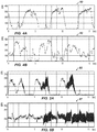
- FIGS. 4A-4B plot examples of stick slip under consideration according to the present disclosure.
- FIGS. 5A-5B plot examples of high frequency torsional oscillation under consideration according to the present disclosure.
- FIG. 6 illustrates a schematic of a control system for the disclosed steering apparatus.
- FIG. 7 illustrates a flow diagram of the control techniques for the disclosed steering apparatus.
- FIG. 8 plots bias and sensitivity of an angular rate sensor relative to temperature.
- FIG. 1 schematically illustrates a drilling system 10 incorporating a rotating steering apparatus 50 according to the present disclosure.
- a downhole drilling assembly 20 drills a borehole 12 penetrating an earth formation 11 .
- the assembly 20 is operationally connected to a drillstring 22 using a suitable connector 21 .
- the drillstring 22 is operationally connected to a rotary drilling rig 24 or other known type of surface drive.
- the downhole assembly 20 includes a control assembly 30 having a sensor section 32 , a power supply section 34 , an electronics section 36 , and a downhole telemetry section 38 .
- the sensor section 32 has various sensing elements, such as directional sensors, accelerometers, magnetometers, and inclinometers, which can be used to indicate the orientation, movement, and other parameters of the downhole assembly 20 within the borehole 12 . This information, in turn, can be used to define the borehole's trajectory for steering purposes.
- the sensor section 32 can also have any other type of sensors used in Measurement-While-Drilling (MWD) and Logging-While-Drilling (LWD) operations including, but not limited to, sensors responsive to gamma radiation, neutron radiation, and electromagnetic fields.
- MWD Measurement-While-Drilling
- LWD Logging-While-Drilling
- the electronics section 36 has electronic circuitry to operate and control other elements within the downhole assembly 20 .
- the electronics section 46 has downhole processor(s) (not shown) and downhole memory (not shown).
- the memory can store directional drilling parameters, measurements made with the sensor section 32 , and directional drilling operating systems.
- the downhole processor(s) can process the measurement data and telemetry data for the various purposes disclosed herein.
- Elements within the downhole assembly 20 communicate with surface equipment 28 using the downhole telemetry section 38 .
- Components of this telemetry section 38 receive and transmit data to an uphole telemetry unit (not shown) within the surface equipment 28 .
- Various types of borehole telemetry systems can be used, including mud pulse systems, mud siren systems, electromagnetic systems, angular velocity encoding, and acoustic systems.
- the power supply section 34 supplies electrical power necessary to operate the other elements within the assembly 20 .
- the power is typically supplied by batteries, but the batteries can be supplemented by power extracted from the drilling fluid by way of a power turbine, for example.
- a drill bit 40 is rotated, as conceptually illustrated by the arrow RB.
- the rotation of the drill bit 40 is imparted by rotation RD of the drillstring 22 at the rotary rig 24 .
- the speed (RPM) of the drillstring rotation RD is typically controlled from the surface using the surface equipment 28 . Additional rotation to the drill bit 40 can also be imparted by a drilling motor (not shown) on the drilling assembly 20 .
- the drilling fluid system or pumps 26 pumps drilling fluid or “mud” from the surface downward and through the drillstring 22 to the downhole assembly 20 .
- the mud exits through the drill bit 40 and returns to the surface via the borehole annulus. Circulation is illustrated conceptually by the arrows 14 .
- the steering apparatus 50 rotates with the drill string 22 in imparting rotation to the drill bit 40 .
- a control system or controller 60 operates, actuates, activates, etc. one or more directional devices 70 a - c on the apparatus 50 .
- multiple devices 70 a - c can be operated independently on the apparatus 50 , and the control system 60 can operate the devices 70 a - c individually using hydraulic, mechanical, and other configurations.
- the control system 60 changes delivery of a portion of the flow of the fluid (circulated drilling mud) to actuate the devices 70 a - c , and the control system 60 in the mechanical configuration changes physical engagement to actuate the devices 70 a - c .
- the independent operation of the multiple directional devices 70 a - c alters the direction of the steering apparatus 50 as it advances the borehole 12 .
- the control system 60 uses orientation information measured by the sensor section 32 cooperating with control information stored in the downhole memory of the electronics section 36 .
- the independent extension/retraction of the directional devices 70 a - c can be coordinated with the orientation of the drilling assembly 20 in the advancing borehole 12 to control the trajectory of drilling.
- the extension/retraction of the directional devices 70 a - c disproportionately engages the drill bit 40 against a certain side in the advancing borehole 12 for directional drilling. (Reference to disproportionate engagement at least means that the engagement in advancing the borehole 12 is periodic, varied, repetitive, selective, modulated, changing over time, etc.)
- a hydraulic configuration of the steering apparatus 50 is schematically shown in more detail in FIG. 2 .
- the controller 60 connects to the control assembly 30 having the sensor section 32 , the power source 34 , etc.
- the controller 60 also connects to each of the one or more directional devices or directors 70 .
- Tele directional devices 70 a - b are schematically shown here for illustrative purposes: the apparatus 50 can have more or less as desired.
- Each directional device 70 a - b includes an actuator 72 and a movable element 76 disposed on the apparatus 50 to rotate therewith.
- Each device 70 a - c is independently operable to move its movable element 76 between an extended condition and a retracted condition relative to the apparatus 50 .
- the actuator 72 can be used for various devices, such as hydraulic valves, electric motors, solenoids, and the like.
- various devices can be used for the movable element 76 , such as pistons, pads, arms, and the like.
- the actuators 72 include hydraulic components to direct a portion of bore flow ( 15 ) (passing through the apparatus 50 from the drill string ( 22 ) to the drill bit ( 40 )) to piston chambers 74 having pistons as the movable elements 76 . Diverted flow ( 17 ) from the actuators 72 can activate these pistons as the movable elements 76 in the piston chambers 74 to move pads 78 to engage the borehole as the apparatus rotates.
- Expelled fluid ( 19 ) from the piston chambers 74 by the actuators 72 can then allow the pads 78 to retract from the borehole as the apparatus 50 rotates.
- other actuators 72 and moveable elements 76 can be used to achieve similar actuations and can rely on hydraulics, mechanical engagement, electric power, or other motive source.
- the steering apparatus 50 steers the assembly ( 20 ) using active deflection as the apparatus 50 rotates with the drill string ( 22 ). Therefore, the steering apparatus 50 of FIG. 2 operates to steer drilling during rotation R about the apparatus' axis A. This rotation R of the apparatus 50 can average 300-rpm or more.
- Each actuator 72 can be operated to extend its piston as the movable elements 76 at the same target position, synchronous to the apparatus' rotation R. Meanwhile, the rotary position of the apparatus 50 is determined by the sensor section 32 and the like of the control system 30 (discussed in more detail later).
- FIGS. 3A-3B schematically illustrate end views of the steering apparatus 50 during operation in two states of operation.
- the steering apparatus 50 has one or more directional devices 70 a - c disposed around the apparatus' housing 51 , such as the three directional devices 70 a - c depicted here.
- the apparatus 50 is capable of controlling multiple actuators (not shown) independently to extend the directional devices 70 a - c as they rotate with the housing 51 .
- the housing 51 having the directional devices 70 a - c rotates with the drillstring ( 22 ), and the housing 51 imparts rotation to the drill bit ( 40 ).
- the transverse displacement of the directional devices 70 a - c can then displace the longitudinal axis of the housing 51 relative to the advancing borehole. This, in turn, tends to change the trajectory of the advancing borehole.
- the independent extensions/retractions of the directional devices 70 a - c are timed relative to a desired direction D to deviate the apparatus 50 during drilling. In this way, the apparatus 50 operates to push the drill bit ( 40 ) to change the drilling trajectory.
- FIGS. 3A-3B show one of the movable directional devices 70 a extended therefrom during a first rotary orientation ( FIG. 3A ) and then during a later rotary orientation ( FIG. 3B ) after the housing 51 has rotated. Because the steering apparatus 50 is rotated along with the drillstring ( 22 ), the operation of the steering apparatus 50 is cyclical to substantially match the period of rotation of the drillstring ( 22 ).
- the orientation of the directional devices 70 a - c is determined by the control system ( 60 ), position sensors, toolface (TF), etc.
- the control system ( 60 ) calculates the orientation of the diametrically opposed position O and instructs the actuators for the directional devices 70 a - c to operate accordingly.
- the control system ( 60 ) may produce the actuation so that one directional device 70 a extends at a first angular orientation (a in FIG. 3A ) relative to the desired direction D and then retracts at a second angular orientation ( ⁇ in FIG. 3B ) in the rotation R of the steering apparatus 50 .
- orientation of the directional device 70 a relative to a reference point is determined using the toolface (TF) of the housing 51 .
- This thereby corresponds to the directional device 70 a being actuated to extend starting at a first angular orientation ⁇ A relative to the toolface (TF) and to retract at a second angular orientation ⁇ B relative to the toolface (TF).
- the toolface (TF) of the housing 51 can be determined by the control system ( 60 ) using the sensors and techniques discussed below.
- the directional device 70 a does not move instantaneously to its extended condition, it may be necessary that the active deflection functions before the directional device 70 a reaches the opposite position O and that the active deflection remains active for a proportion of each rotation R.
- the directional device 70 a can be extended during a segment or width S of the rotation R best suited for the directional device 70 a to extend and retract relative to the housing 51 and engage the borehole to deflect the housing 51 .
- the RPM of the housing's rotation R, the drilling direction D relative to the toolface (TF), the operating metrics of the directional device 70 a , and other factors involved can be used to define the segment S.
- angles ⁇ and ⁇ are equally-spaced to either side of the position O, but because it is likely that the directional device 70 a will extend gradually (and in particular more slowly than it will retract) it may be preferable that the angle ⁇ is closer to the position O than is the angle ⁇ .
- the steering apparatus 50 as disclosed herein has the additional directional devices 70 b - c arranged at different angular orientations about the housing's circumference. Extension and retraction of these additional directional devices 70 b - c can be comparably controlled in conjunction with what has been discussed above with reference to FIGS. 3A-3B so that the control system ( 60 ) can coordinate multiple retractions and extensions of the serval directional devices 70 a - c during each of (or one or more of) the rotations R.
- the displacement of the housing 51 and directional devices 70 a - c can be timed with the rotation R of the drillstring ( 22 ) and the apparatus 50 based on the orientation of the steering apparatus 50 in the advancing borehole.
- the displacement can ultimately be timed to direct the drill bit ( 40 ) in a desired drilling direction D and can be performed with each rotation or any subset of the rotations.
- the steering apparatus 50 uses a reference to the apparatus' angular position while drilling so the steering apparatus 50 can steer the advancing borehole in the correct direction. Because the steering apparatus 50 rotates in the advancing borehole and experiences a number of disturbances in the process, the rotational speed of the apparatus 50 can vary significantly over the course of several and even a single rotation.
- stick-slip is one type of disturbance that can occur in the rotational speed of the steering apparatus 50 .
- Stick-slip of the bottom hole assembly can produce inaccuracies that cause significant difficulties in controlling the trajectory of the borehole. Therefore, accurate angular position of the steering apparatus 50 in high resolution is beneficial to system performance, allowing the steering apparatus 50 to better compensate for downhole dynamics.
- features of the disclosed steering apparatus 50 , control system 60 , control techniques, and the like are directed to addressing these problems.
- control system 60 seeks to accurately control the actuators ( 72 ) for the directional devices ( 70 a - c ) under various downhole disturbances, such as stick-slip conditions. Additionally, the control system 60 seeks to be self-calibrating during operations so that a build-up of inaccuracies can be avoided.
- FIGS. 4A-4B plot examples of stick slip under consideration according to the present disclosure. These plots 80 and 82 are merely explanatory.
- stick-slip can cause the rotational speed (RPM) of a bottom hole assembly having the disclosed steering apparatus ( 50 ) to oscillate from stick conditions (about 0 RPMs) to slip conditions (elevated RPMs), when the torsion built-up in the drill string during the stick condition releases and the RPM of the bottom hole assembly well exceeds the average RPMs being imparted to the bottom hole assembly for the drilling conditions.
- RPMs can reach above 300 RPM in the slip conditions, and the stick slip oscillations can be cyclical in a more or less uniform fashion when the bottom hole assembly tends to engage roughly the same side of the borehole.
- FIG. 4B shows the plot 82 of a stick slip condition that is more complex in character.
- the slip conditions of increased RPM can exceed the resolution of sensing capabilities in a given control system to an extent that the given control system incorrectly determines angular orientation. This in turn would lead to incorrect actuation of the apparatus so that the direction of the advancing borehole would be incorrect.
- the disclosed steering apparatus 50 has control and sensing capabilities to at least better handle disturbances, such as forms of stick-slip discussed herein.
- high frequency torsional oscillation can be another downhole disturbance under consideration according to the present disclosure.
- FIGS. 5A-5B plot examples of these types of oscillations. Again, these plots 85 and 87 are merely explanatory.
- the RPMs of a bottom hole assembly can oscillate at a high frequency over a short period of time between lower and upper RPM values. For instance, one set of oscillations changes rapidly in a short time period between about 50-RPM to about 225-RPM. A later oscillation changes rapidly in another short time period between about 75-RPM to about 250-RPM.
- the high frequency torsional oscillations can extend over longer periods of time, such as shown in the plot 87 of FIG. 5B .
- the high frequency oscillations of RPM can exceed the resolution of sensing capabilities in a given control system to an extent that the given control system incorrectly determines angular orientation. This in turn would lead to incorrect actuation of the apparatus so that the direction of the advancing borehole would be incorrect. Again for this reason, the disclosed steering apparatus 50 has control and sensing capabilities to at least better handle disturbances, such as forms of high frequency torsional oscillation discussed herein.
- the control system 60 preferably includes accurate sensors and sensing capabilities.
- the control system 60 preferably includes an angular rate gyroscope sensor (ARG) with a scaled output range between ⁇ 2000°/Sec and ⁇ 5000°/Sec.
- the control system 60 preferably includes an angular position sensor (APS) having magnetic detectors orthogonally oriented at two-axes and capable of detecting the earth's magnetic field.
- ARG angular rate gyroscope sensor
- APS angular position sensor
- the various sensors of the control system 60 have sources of error that the control system 60 preferably accounts for to improve accuracy.
- the angular position sensor (APS) of the control system 60 has sources of error that include bias, scale, and misalignment.
- the bias of the sensor can be determined as an average, and compensations based on the average bias can be applied to the angular position readings.
- Misalignment of how the angular position sensor is installed in the apparatus 50 can be initially determined and similarly accounted for.
- the scale of angular position sensor (APS) is preferably corrected so that the X and Y readings are scaled for relative comparison to one another.
- sensing of the tool face has similar errors that include bias, scale, and misalignments, similar accommodations can be made for sensing of the tool face with the control system 60 .
- the Angular Rate Gyroscope (ARG) of the control system 60 has somewhat different sources of error that include bias and sample period jitter.
- the bias of the Angular Rate Gyroscope (ARG) is preferably accounted for in adjusting the angular rate readings.
- the sample period jitter of the Angular Rate Gyroscope (ARG) can be known and applied to readings as needed.
- FIG. 8 plots bias 90 and sensitivity 92 determined experimentally for an angular rate sensor (ARG) relative to temperature.
- the bias 90 of the angular rate sensor remains relative steady from 25 C to about 145 C, but then drops sharply.
- Sensitivity 92 of the angular rate sensor also remains relative steady from 25 C to about 145 C, and only rises slowly thereafter.
- the control system 60 for the disclosed apparatus 50 can account for such bias 90 and sensitivity 92 relative to temperature, as in affects sensors such as the angular rate sensor, to improve operation of the system 60 during drilling.
- the control system 60 preferably performs self-calibration during operations.
- the form of calibrations at least include angular position and angular rate calibrations.
- angular position calibration discussed in more detail below, for example, the mechanical misalignment of X-Y magnetometers of the control system 60 is applied to magnetometer readings. Also, corrections for the X-Y rotating biases and the X-Y rotating scales are applied to the magnetometer readings.
- the bias of an angular rate sensor of the control system 60 is determined when pumps ( 26 ) are off and the drillstring ( 22 ) is not rotating during drillpipe connections.
- the angular rate readings obtained during rotations are then corrected for that bias, and any rotating scale of the readings can be corrected.
- FIG. 6 illustrates a schematic of a control system 100 for the disclosed steering apparatus 50 .
- the control system 100 as depicted here can combine or can be part of one or more previously disclosed elements, such as the control assembly 30 , control system 60 , etc., which are consolidated in the description here. Separate reference to some of these components may have been made previously in the disclosure for the sake of simplicity.
- the control system 100 includes a processing unit 110 having processor(s), memory, etc. Sensor elements or “sensors” 120 , 130 , and 170 interface with the processing unit 110 and may use one or more analog-to-digital converters 140 to do so.
- the control system 100 uses an angular rate gyroscope to determine an angular rate of the apparatus 50 , and readings from a magnetometer give a highside of the apparatus 50 for orientation of the apparatus 50 relative to the borehole.
- various sensor elements can include inclinometers, magnetometers, accelerometers, and other sensors that provide position information to the processing unit 110 .
- an inclinometer and azimuthal sensor element 120 can include a near-bit azimuthal sensor 122 and a near-bit inclinometer sensor 124 , which may use magnetometers and Z-axis accelerometers.
- a static toolface sensor 126 can provide the toolface of the apparatus ( 50 ) and can have X and Y axes accelerometers.
- a temperature sensor 128 can provide temperature readings.
- an angular rate gyroscope (ARG) sensor 130 can provide the angular rate of the apparatus ( 50 ) during operation for obtaining position readings.
- the processing unit 110 also communicates with an angular position sensor (APS) 170 , which provides static magnetic toolface and detects the rotary quadrant of the apparatus ( 50 ) during operation.
- the processing unit 110 can communicate with other components of the apparatus ( 50 ) via communication circuitry 112 and a bus and can store information in logging memory 114 .
- the processing unit 110 interfaces with multiple actuator modules 160 - 1 , 160 - 2 , 160 - 3 of the apparatus ( 50 ), which are used to actuate the various directional devices as noted herein.
- the actuator modules 160 - 1 , 160 - 2 , 160 - 3 may use sensors 164 to monitor the operation (e.g., state, position, etc.) of the actuators using feedback to the processing unit 110 .
- the sensors 164 can be pressure transducers used to determine the actuators' operations in the first instance.
- the pressure transducers can also provide pressure readings that can also help determine wear and to verify overall operation.
- the control system 100 operates based on discrete position information obtained with the various sensor elements 122 , 124 , 126 , 130 , 170 , etc.
- the resolution of the position information can be 0.5 ms @ 300 rpm, which would can give an angular resolution of about 0.9° for the apparatus' rotation.
- the angular rate gyroscope sensor 130 is used in conjunction with X-Y crossovers from the APS 170 to obtain position information at about 3-kHz.
- the X-Y accelerometers obtain an offset value of static gravity to magnetic highside for determining toolface of the apparatus ( 50 ).
- the processing unit 110 processes the input of the various sensor readings and can monitor the operation (e.g., state, position, etc.) of the actuators using feedback from the modules' sensors 164 . In turn, the processing unit 110 provides actuator control signals to the actuator modules 160 - 1 , 160 - 2 , and 160 - 3 to steer the apparatus ( 50 ).
- FIG. 7 illustrates a flow diagram of a control process 200 used by the control system 100 as in FIG. 6 of the disclosed steering apparatus 50 .
- the control process 200 combines the operation of the angular position sensor ( 170 ), the angular rate sensor ( 130 ), and an analog-to-digital converter ( 140 ) together to develop director actuations 290 for the actuator modules ( 160 ) based on a target toolface 282 .
- the angular position sensor ( 170 ) obtains measurements and is calibrated during rotation in a measurement and calibration process 270 to produce calibrated magnetometer readings 210 .
- a toolface offset (TFO) 257 between a magnetic toolface (MTF) 254 and a highside toolface (HSTF) 256 of the apparatus ( 50 ) is determined periodically in an offset calculation process 250 .
- the bias 232 of the angular rate sensor ( 130 ) is also measured periodically so that the bias correction 234 can be applied to the readings from the angular rate sensor ( 130 ).
- the calibrated magnetometer readings 210 and the calculated toolface offset (TFO) 257 are combined in a datum reference calculation 220 that is used to re-datum the accumulation of readings from the angular rate sensor ( 130 ).
- the magnetometer(s) for the angular position sensor(s) ( 170 ) are used to re-sync the angular rate sensor (ARG) ( 130 ) at least one zero crossing point. All position based control and/or measurements are based upon the calibrated angle provided by the angular rate sensor 130 .
- the accumulated angular rate readings in an accumulator 236 are used to determine director actuation calculations 280 based on the target toolface 282 so that the counts of the analog-to-digital converter ( 140 ) can be properly sampled and the processing unit ( 110 ) can operate the actuator modules ( 160 ) of the apparatus ( 50 ).
- the angular position measurement steps 270 may not strictly require “calibrated” magnetometers or accelerometers to function.
- an ArcTan of the measurements from the sensors would be used to compute instantaneous toolface.
- the magnitudes of the measurements involved in the typical arrangement would be important.
- the process 200 of the present disclosure instead uses zero-crossings (see zero-crossing detector 212 ). Therefore, the magnitudes of the magnetometer and accelerometer waveforms are of less importance as long as a sufficient signal-to-noise ratio exists for zero-crossing events to be detected. (As an aside, bias and misalignment may still need to be applied to get accurate zero-crossings at the cross points (i.e., 90° points).
- an integrated angular rate obtained from the calibrated angular rate gyroscope sensor 130 fills in the positional information between the zero-crossings 212 to deliver a high-resolution hybrid angular position system.
- the angular position sensor ( 170 ) obtains magnetometer readings Bx-By. To account for errors due to bias and scale with the angular position sensor ( 170 ), calculations of the X-Y bias 272 and X-Y scale 274 are made, and a misalignment factor 276 is also applied so that a calibration 278 can be applied. As will be appreciated, the angular position sensor ( 170 ) accumulates rolling errors during rotation so that the errors are corrected in the process 270 .
- correction 272 for instance, average bias in both X and Y directions is calculated as the apparatus ( 50 ) rotates, and the X-Y magnetometer readings of the angular position sensor ( 170 ) are corrected for that average bias.
- correction 274 the higher amplitude of the magnetometer reading in X or Y directions is used to scale the lower amplitude reading so that the X-Y magnetometer readings of the angular position sensor ( 170 ) are corrected for scale.
- the misalignment is essentially a constant offset value based on how the X-Y magnetometer of the angular position sensor ( 170 ) is installed in the apparatus ( 50 ). With the corrections applied in step 278 , calibrated X-Y magnetometer readings 210 are produced.
- the calibrated magnetometer readings 210 are fed into a detector 212 to determine states in X-Y for the datum reference process 220 .
- states in X-Y for the datum reference process 220 .
- four zero-crossing states are determined per each revolution using a zero-crossing detector that finds when the sine and cosine signals of the X-Y magnetometer readings cross zero, which may simply lend itself to ready detection.
- any other number of states can be determined for any partial revolution or any group of revolutions.
- the number of states can be matched to the number of detector actuators of the apparatus ( 50 ) to simplify later calculations.
- the system ( 100 ) can use a single magnetometer component to re-sync the angular rate sensor (ARG) measurements at zero crossing points. Additionally, use of one magnetometer component for the angular position sensor ( 170 ) may not require a misalignment calibration. However, using a single magnetometer component may require a bias calibration to insure that the zero crossings (re-sync points) are properly spaced (e.g., 180° apart).
- the bias calibration may not need to be particularly accurate. At most, the system ( 100 ) may only need to ensure that the magnetometer measurement crosses zero twice per revolution.
- the calibrated magnetometer readings 210 are also fed into the offset calculation process 250 .
- this process 250 is determined periodically when the pumps are off and the apparatus ( 50 ) is not rotating, such as when a drill pipe connection is being made at the surface.
- the process 250 starts after an initial time (T1) 252 of the pumps being off 251 .
- Rotation 253 of the apparatus ( 50 ) is checked. If the apparatus ( 50 ) is not rotating, then the process 250 calculates the magnetic toolface (MTF) 254 using the calibrated magnetometer readings 210 . Because the magnetometer is not rotating, any previous X-Y bias, X-Y scale, and the like determined for the angular position sensor ( 270 ) is stored in memory and applied to the calculation of the magnetic toolface (MTF) 254 .
- the process 250 also calculates the highside toolface (HSTF) 256 using static toolface measurements from accelerometers or the like. These two toolface readings MTF 254 and HSTF 256 are then used to calculate the toolface offset 257 , which is used to orient the dynamic X-Y magnetometer readings to a static reference position.
- the calculated toolface offset (TFO) 257 is then fed into the datum reference process 220 as an adjustment toolface offset 224 to the dynamic X-Y magnetometer readings for the magnetic toolface from the angular position sensor ( 170 ) during revolutions.
- this toolface offset (TFO) 257 of the magnetic toolface 254 relative to the highside toolface 256 can be a relatively constant value of the drilling distance of one stand of drill pipe.
- the toolface offset (TFO) 257 can vary as much as 15-degrees because the offset 257 may generally depend on the inclination and azimuth of the apparatus ( 50 ) while drilling. Accordingly, the calculation of the toolface offset (TFO) 257 may be adjusted by dynamic parameters 258 , which may be in the form of constant values, variables, and equations based on the inclination and azimuth of the apparatus ( 50 ) while drilling.
- the bias 232 of the angular rate sensor ( 130 ) is also measured.
- the measured bias 234 is a relatively stable value so that evaluating the bias at each drillpipe connection may be sufficient.
- the angular rate reading bias 232 can be at least periodically measured when the apparatus ( 50 ) is rotating in the borehole. To do this, the process finds two periods in which average rotation rates are different. The angular rate gyroscope (ARG) counts and the RPM delta between these two periods can then be used to calculate a form a scale factor of raw counts per RPM. In other words, from these two period, a ratio is calculated of a count of the angular rate readings relative to a difference in the rotation rates. The angular rate reading bias can then be determined by linearly extrapolating the ratio for either of these two periods to a point of no rotation (i.e., 0 RPM), which will indicate the bias.
- ARG angular rate gyroscope
- the measured bias 234 is applied to the angular rate readings from the angular rate sensor ( 130 ).
- the angular rate readings from the angular rate sensor ( 130 ) may also go through a dynamic scaling process 235 .
- the sensitivity of the angular rate sensor ( 130 ) is reduced at the higher temperatures.
- a dynamic scale factor can be used to extend the operating range of the angular rate sensor ( 130 ) and provide for more accurate measurements. This scaling may be done for one or more revolutions based on the zero crossings as sync points.
- the process 235 calibrates the readings of the angular rate sensor ( 130 ) with the readings of the angular position sensor ( 170 ).
- the process 235 determines a dynamic scale factor to apply to the angular rate measure by using two accumulators 237 a - b and mathematical calculation.
- a first accumulator 237 a is used to track the total number of degrees that the angular position sensor ( 170 ) has moved (i.e., “Total Degrees APS”).
- An additional accumulator 237 b is used to track the total number of counts from the analog-to-digital converter 140 have been gathered from the angular rate sensor ( 130 ) (i.e., “Total ARG ADC Counts”). Both accumulators 237 a - b sum over the same period.
- the ARG scale factor Periodically (e.g., based upon degrees traversed), the ARG scale factor is calculated by dividing the “Total Degrees APS” 237 a by the “Total ARG ADC Counts” 237 b . This newly calculated ARG scale factor (degrees per ARG ADC count) can then be used to compensate the ADC counts of angular rate sensor ( 130 ) until a subsequent scale factor is ready.
- the dynamic ARG scale factor will be more accurate when a larger the number of degrees are traveled for the accumulation and calculation.
- the scaling process 235 is not sensitive to stick-slip conditions.
- the datum reference process 220 uses the calibrated magnetometer readings 210 and the calculated adjustment toolface offset 224 to calculate seed counts 226 of the acquisition for seed angles in the apparatus's rotation. The calculation of the seed counts 226 is based on a stored configuration 228 for the apparatus ( 50 ).
- the stored configuration 220 can be preset and can be different as needed for a given implementation.
- the configuration 228 sets a particular sample period for measurement, dictates the number of bits for ADC, provides a range and span of RPMs, gives a measurement resolution of RPM relative to count (i.e., degrees of rotation). Example information for one such configuration 228 is depicted here.
- the datum reference process 220 calculates the seed counts 226 for the various MTF or seed angles, such as 0, 90, 180, 270-degrees.
- the seed counts 226 are then used in processing (i.e., adjusting, re-orienting, etc.) the accumulated angular rate readings in the accumulator 236 for the director actuations 290 at particular seed counts (i.e., angles). In this way, the angular rate readings can be seeded in the actuation calculation process 280 for the given target toolface 282 to advance the borehole in the desired direction.
- the apparatus ( 50 ) in this example has three actuator modules 160 (i.e., actuators, directors, etc.), although the apparatus ( 50 ) may in general having one or more actuators.
- the actuators for the modules ( 160 ) are arranged uniformly at every 120-degrees about the circumference of the apparatus ( 50 ), but any arrangement could be used.
- the target toolface 282 in degrees is divided into the geometrical arrangement of the actuators on the apparatus ( 50 ) (i.e., three pistons arranged symmetrically about the apparatus' circumference at 120-degress from one another).
- Start 292 of the actuation (shown in degrees/speed counts), stop 294 of the actuation (shown in degrees/speed counts), and width 296 of the actuation (shown in degrees/speed counts) are determined for each of the pads 284 of the actuator module ( 160 ) so as to move the apparatus ( 50 ) toward the target toolface 282 .
- These actuations 292 , 294 are fed to the analog to digital converter 140 in time (T2) 286 so the processing unit ( 110 ) can operate the actuator modules ( 160 ) accordingly.
- the target toolface 282 is provided to the processing unit ( 110 ) as part of the drilling operations and may be dictated from control signals in memory, from telemetry, from on-board sensing and calculation, etc.
- teachings of the present disclosure can be used in other implementations, such as in measurement-while-drilling (MWD) or logging-while-drilling (LWD) implementations.
- MWD measurement-while-drilling
- LWD logging-while-drilling
- teachings of the present disclosure can be used when measuring/logging with at least one sensor on an apparatus in a borehole, either in addition to or instead of the directional drilling disclosed here.
- the sensor section 32 of the downhole assembly 20 can have any type of sensors used in Measurement-While-Drilling (MWD) and Logging-While-Drilling (LWD) operations including, but not limited to, sensors responsive to gamma radiation, neutron radiation, and electromagnetic fields.
- MWD Measurement-While-Drilling
- LWD Logging-While-Drilling
- at least one sensor 33 in the sensor section 32 advances in the borehole 12 while rotation is imparted to the assembly 20 . Consequently, the at least one sensor 33 senses measurements while rotation is imparted to the assembly 20 advancing in the borehole 12 .
- angular rate readings are obtained of the rotation of the assembly 20
- angular position readings are obtained of the assembly 20 during the rotation.
- the present technique then adjusts the angular rate readings based at least on the angular position readings to determine angular positions of the assembly 20 in the manner disclosed herein.
- one or more the measurements of the at least one sensor 33 sensing during the rotation can be correlated to the determined angular positions.
- an image can be generated using known imaging method from the one or more correlated measurements.
- the results can give high resolution angular position measurements that can improve the quality of log images, wellbore surveys, and the like.
- the correlation can allow for targeted sensing by the at least one sensor 33 of the sensing section 32 .
- the one or more measurements sensed with the at least one sensor 33 at one or more sensed directions during the rotation can be correlated to one or more targeted directions of the determined angular positions.
- the result is that the at least one sensor 33 can sense towards (or be correlated to) the one or more targeted directions based on the determined angular positions.
Abstract
Description
Claims (20)
Priority Applications (1)
| Application Number | Priority Date | Filing Date | Title |
|---|---|---|---|
| US16/532,771 US11136877B2 (en) | 2016-09-30 | 2019-08-06 | Control for rotary steerable system |
Applications Claiming Priority (2)
| Application Number | Priority Date | Filing Date | Title |
|---|---|---|---|
| US15/282,379 US10415363B2 (en) | 2016-09-30 | 2016-09-30 | Control for rotary steerable system |
| US16/532,771 US11136877B2 (en) | 2016-09-30 | 2019-08-06 | Control for rotary steerable system |
Related Parent Applications (1)
| Application Number | Title | Priority Date | Filing Date |
|---|---|---|---|
| US15/282,379 Continuation US10415363B2 (en) | 2016-09-30 | 2016-09-30 | Control for rotary steerable system |
Publications (2)
| Publication Number | Publication Date |
|---|---|
| US20200072033A1 US20200072033A1 (en) | 2020-03-05 |
| US11136877B2 true US11136877B2 (en) | 2021-10-05 |
Family
ID=59714121
Family Applications (2)
| Application Number | Title | Priority Date | Filing Date |
|---|---|---|---|
| US15/282,379 Active 2037-04-19 US10415363B2 (en) | 2016-09-30 | 2016-09-30 | Control for rotary steerable system |
| US16/532,771 Active US11136877B2 (en) | 2016-09-30 | 2019-08-06 | Control for rotary steerable system |
Family Applications Before (1)
| Application Number | Title | Priority Date | Filing Date |
|---|---|---|---|
| US15/282,379 Active 2037-04-19 US10415363B2 (en) | 2016-09-30 | 2016-09-30 | Control for rotary steerable system |
Country Status (4)
| Country | Link |
|---|---|
| US (2) | US10415363B2 (en) |
| EP (2) | EP4219893A1 (en) |
| CA (1) | CA3034615C (en) |
| WO (1) | WO2018063543A1 (en) |
Families Citing this family (6)
| Publication number | Priority date | Publication date | Assignee | Title |
|---|---|---|---|---|
| WO2019118185A1 (en) * | 2017-12-14 | 2019-06-20 | Halliburton Energy Services, Inc. | Noise robust algorithm for measuring gravitational tool-face |
| WO2019232516A1 (en) | 2018-06-01 | 2019-12-05 | Schlumberger Technology Corporation | Estimating downhole rpm oscillations |
| US11573139B2 (en) * | 2019-08-16 | 2023-02-07 | Baker Hughes Oilfield Operations Llc | Estimation of downhole torque based on directional measurements |
| US11916507B2 (en) | 2020-03-03 | 2024-02-27 | Schlumberger Technology Corporation | Motor angular position control |
| US11933156B2 (en) | 2020-04-28 | 2024-03-19 | Schlumberger Technology Corporation | Controller augmenting existing control system |
| US20230098032A1 (en) * | 2021-09-24 | 2023-03-30 | Halliburton Energy Services, Inc. | Velocity Correction With Joint Inversion |
Citations (46)
| Publication number | Priority date | Publication date | Assignee | Title |
|---|---|---|---|---|
| US4416339A (en) | 1982-01-21 | 1983-11-22 | Baker Royce E | Bit guidance device and method |
| US5685379A (en) * | 1995-02-25 | 1997-11-11 | Camco Drilling Group Ltd. Of Hycalog | Method of operating a steerable rotary drilling system |
| US5706905A (en) | 1995-02-25 | 1998-01-13 | Camco Drilling Group Limited, Of Hycalog | Steerable rotary drilling systems |
| EP1008717A1 (en) | 1998-12-11 | 2000-06-14 | Schlumberger Holdings Limited | Rotary steerable well drilling system utilizing sliding sleeve |
| US6092610A (en) | 1998-02-05 | 2000-07-25 | Schlumberger Technology Corporation | Actively controlled rotary steerable system and method for drilling wells |
| US6109370A (en) | 1996-06-25 | 2000-08-29 | Ian Gray | System for directional control of drilling |
| US6116354A (en) | 1999-03-19 | 2000-09-12 | Weatherford/Lamb, Inc. | Rotary steerable system for use in drilling deviated wells |
| US6290003B1 (en) | 1999-01-30 | 2001-09-18 | Smart Stabilizer Systems Limited | Controllable stabilizer |
| US6315062B1 (en) | 1999-09-24 | 2001-11-13 | Vermeer Manufacturing Company | Horizontal directional drilling machine employing inertial navigation control system and method |
| US6470974B1 (en) | 1999-04-14 | 2002-10-29 | Western Well Tool, Inc. | Three-dimensional steering tool for controlled downhole extended-reach directional drilling |
| US20040016571A1 (en) | 2002-05-15 | 2004-01-29 | Baker Hughes Incorporated | Closed loop drilling assembly with electronics outside a non-rotating sleeve |
| US20040222023A1 (en) | 2003-05-10 | 2004-11-11 | Marc Haci | Continuous on-bottom directional drilling method and system |
| US6837315B2 (en) | 2001-05-09 | 2005-01-04 | Schlumberger Technology Corporation | Rotary steerable drilling tool |
| US6840336B2 (en) | 2001-06-05 | 2005-01-11 | Schlumberger Technology Corporation | Drilling tool with non-rotating sleeve |
| US7004263B2 (en) | 2001-05-09 | 2006-02-28 | Schlumberger Technology Corporation | Directional casing drilling |
| US20060243487A1 (en) | 2005-04-29 | 2006-11-02 | Aps Technology, Inc. | Rotary steerable motor system for underground drilling |
| US20060249287A1 (en) | 2005-05-05 | 2006-11-09 | Schlumberger Technology Corporation | Steerable drilling system |
| US7360610B2 (en) | 2005-11-21 | 2008-04-22 | Hall David R | Drill bit assembly for directional drilling |
| US7510027B2 (en) | 2004-07-09 | 2009-03-31 | Halliburton Energy Services, Inc. | Borehole drilling control system, method and apparatus |
| US7510029B2 (en) | 2005-08-23 | 2009-03-31 | The Charles Machine Works, Inc. | System for tracking and maintaining an on-grade horizontal borehole |
| US20090222209A1 (en) | 2008-02-29 | 2009-09-03 | Marian Morys | Apparatus and method for motion correction to sensor measurements |
| US20090260884A1 (en) | 2008-04-16 | 2009-10-22 | Baker Hughes Incorporated | Steering Device for Downhole Tools |
| US20100163308A1 (en) | 2008-12-29 | 2010-07-01 | Precision Energy Services, Inc. | Directional drilling control using periodic perturbation of the drill bit |
| US7766098B2 (en) | 2007-08-31 | 2010-08-03 | Precision Energy Services, Inc. | Directional drilling control using modulated bit rotation |
| US20110066392A1 (en) | 2009-09-14 | 2011-03-17 | Honeywell International Inc. | Systems and methods for calibration of gyroscopes and a magnetic compass |
| US20110266063A1 (en) | 2003-11-26 | 2011-11-03 | Geoff Downton | Steerable drilling system |
| US20120018225A1 (en) | 2010-07-21 | 2012-01-26 | Baker Hughes Incorporated | Tilted bit rotary steerable drilling system |
| GB2486811A (en) | 2010-12-23 | 2012-06-27 | Schlumberger Holdings | Rotary steerable system |
| US20120160563A1 (en) | 2010-12-23 | 2012-06-28 | Brian Clark | System and method for controlling steering in a rotary steerable system |
| US8255163B2 (en) | 2008-09-30 | 2012-08-28 | Precision Energy Services, Inc. | Downhole drilling vibration analysis |
| US20130092439A1 (en) | 2011-10-14 | 2013-04-18 | Precision Energy Services, Inc. | Analysis of Drillstring Dynamics Using an Angular Rate Sensor |
| US8528636B2 (en) | 2006-09-13 | 2013-09-10 | Baker Hughes Incorporated | Instantaneous measurement of drillstring orientation |
| US20140163888A1 (en) | 2012-12-10 | 2014-06-12 | Schlumberger Technology Corporation | Weighting Function For Inclination And Azimuth Computation |
| US8781746B2 (en) | 2007-08-30 | 2014-07-15 | Precision Energy Services, Inc. | System and method for obtaining and using downhole data during well control operations |
| US8827006B2 (en) | 2005-05-12 | 2014-09-09 | Schlumberger Technology Corporation | Apparatus and method for measuring while drilling |
| US20140262507A1 (en) | 2013-03-12 | 2014-09-18 | Weatherford/Lamb, Inc. | Rotary steerable system for vertical drilling |
| WO2014196958A1 (en) | 2013-06-04 | 2014-12-11 | Halliburton Energy Services, Inc. | Dynamic geo-stationary actuation for a fully-rotating rotary steerable system |
| WO2015127345A2 (en) | 2014-02-24 | 2015-08-27 | Weatherford/Lamb, Inc. | Eccentric stabilizer for synchronous rotary steerable system |
| US20150337601A1 (en) | 2012-07-11 | 2015-11-26 | Schlumberger Technology Corporation | Drilling System with Flow Control Valve |
| US20160002978A1 (en) | 2014-07-07 | 2016-01-07 | Schlumberger Technology Corporation | Steering System for Drill String |
| US9347279B2 (en) | 2012-02-28 | 2016-05-24 | Smart Stabilizer Systems Limited | Torque control device for a downhole drilling assembly |
| US9366131B2 (en) | 2009-12-22 | 2016-06-14 | Precision Energy Services, Inc. | Analyzing toolface velocity to detect detrimental vibration during drilling |
| US9567844B2 (en) | 2013-10-10 | 2017-02-14 | Weatherford Technology Holdings, Llc | Analysis of drillstring dynamics using angular and linear motion data from multiple accelerometer pairs |
| US20180252088A1 (en) | 2015-10-12 | 2018-09-06 | Halliburton Energy Services, Inc. | Rotary Steerable Drilling Tool and Method |
| US10100630B2 (en) | 2014-02-12 | 2018-10-16 | Weatherford Technology Holdings, Llc | Method and apparatus for communicating incremental depth and/or other useful data of a downhole tool |
| US10641077B2 (en) * | 2017-04-13 | 2020-05-05 | Weatherford Technology Holdings, Llc | Determining angular offset between geomagnetic and gravitational fields while drilling wellbore |
Family Cites Families (1)
| Publication number | Priority date | Publication date | Assignee | Title |
|---|---|---|---|---|
| JP2016016633A (en) * | 2014-07-10 | 2016-02-01 | キヤノン株式会社 | Recording element substrate, liquid discharge head, and liquid discharge device |
-
2016
- 2016-09-30 US US15/282,379 patent/US10415363B2/en active Active
-
2017
- 2017-08-15 EP EP23173620.8A patent/EP4219893A1/en active Pending
- 2017-08-15 WO PCT/US2017/046883 patent/WO2018063543A1/en unknown
- 2017-08-15 CA CA3034615A patent/CA3034615C/en active Active
- 2017-08-15 EP EP17758341.6A patent/EP3519675B1/en active Active
-
2019
- 2019-08-06 US US16/532,771 patent/US11136877B2/en active Active
Patent Citations (51)
| Publication number | Priority date | Publication date | Assignee | Title |
|---|---|---|---|---|
| US4416339A (en) | 1982-01-21 | 1983-11-22 | Baker Royce E | Bit guidance device and method |
| US5685379A (en) * | 1995-02-25 | 1997-11-11 | Camco Drilling Group Ltd. Of Hycalog | Method of operating a steerable rotary drilling system |
| US5706905A (en) | 1995-02-25 | 1998-01-13 | Camco Drilling Group Limited, Of Hycalog | Steerable rotary drilling systems |
| US6109370A (en) | 1996-06-25 | 2000-08-29 | Ian Gray | System for directional control of drilling |
| US6092610A (en) | 1998-02-05 | 2000-07-25 | Schlumberger Technology Corporation | Actively controlled rotary steerable system and method for drilling wells |
| US6158529A (en) | 1998-12-11 | 2000-12-12 | Schlumberger Technology Corporation | Rotary steerable well drilling system utilizing sliding sleeve |
| EP1008717A1 (en) | 1998-12-11 | 2000-06-14 | Schlumberger Holdings Limited | Rotary steerable well drilling system utilizing sliding sleeve |
| US6290003B1 (en) | 1999-01-30 | 2001-09-18 | Smart Stabilizer Systems Limited | Controllable stabilizer |
| US6116354A (en) | 1999-03-19 | 2000-09-12 | Weatherford/Lamb, Inc. | Rotary steerable system for use in drilling deviated wells |
| US6470974B1 (en) | 1999-04-14 | 2002-10-29 | Western Well Tool, Inc. | Three-dimensional steering tool for controlled downhole extended-reach directional drilling |
| US6315062B1 (en) | 1999-09-24 | 2001-11-13 | Vermeer Manufacturing Company | Horizontal directional drilling machine employing inertial navigation control system and method |
| US7004263B2 (en) | 2001-05-09 | 2006-02-28 | Schlumberger Technology Corporation | Directional casing drilling |
| US6837315B2 (en) | 2001-05-09 | 2005-01-04 | Schlumberger Technology Corporation | Rotary steerable drilling tool |
| US6840336B2 (en) | 2001-06-05 | 2005-01-11 | Schlumberger Technology Corporation | Drilling tool with non-rotating sleeve |
| US20040016571A1 (en) | 2002-05-15 | 2004-01-29 | Baker Hughes Incorporated | Closed loop drilling assembly with electronics outside a non-rotating sleeve |
| US6913095B2 (en) | 2002-05-15 | 2005-07-05 | Baker Hughes Incorporated | Closed loop drilling assembly with electronics outside a non-rotating sleeve |
| US20040222023A1 (en) | 2003-05-10 | 2004-11-11 | Marc Haci | Continuous on-bottom directional drilling method and system |
| US20110266063A1 (en) | 2003-11-26 | 2011-11-03 | Geoff Downton | Steerable drilling system |
| US7510027B2 (en) | 2004-07-09 | 2009-03-31 | Halliburton Energy Services, Inc. | Borehole drilling control system, method and apparatus |
| US20060243487A1 (en) | 2005-04-29 | 2006-11-02 | Aps Technology, Inc. | Rotary steerable motor system for underground drilling |
| US20060249287A1 (en) | 2005-05-05 | 2006-11-09 | Schlumberger Technology Corporation | Steerable drilling system |
| US8827006B2 (en) | 2005-05-12 | 2014-09-09 | Schlumberger Technology Corporation | Apparatus and method for measuring while drilling |
| US7510029B2 (en) | 2005-08-23 | 2009-03-31 | The Charles Machine Works, Inc. | System for tracking and maintaining an on-grade horizontal borehole |
| US7360610B2 (en) | 2005-11-21 | 2008-04-22 | Hall David R | Drill bit assembly for directional drilling |
| US8528636B2 (en) | 2006-09-13 | 2013-09-10 | Baker Hughes Incorporated | Instantaneous measurement of drillstring orientation |
| US8781746B2 (en) | 2007-08-30 | 2014-07-15 | Precision Energy Services, Inc. | System and method for obtaining and using downhole data during well control operations |
| US7766098B2 (en) | 2007-08-31 | 2010-08-03 | Precision Energy Services, Inc. | Directional drilling control using modulated bit rotation |
| US20090222209A1 (en) | 2008-02-29 | 2009-09-03 | Marian Morys | Apparatus and method for motion correction to sensor measurements |
| US20090260884A1 (en) | 2008-04-16 | 2009-10-22 | Baker Hughes Incorporated | Steering Device for Downhole Tools |
| US8255163B2 (en) | 2008-09-30 | 2012-08-28 | Precision Energy Services, Inc. | Downhole drilling vibration analysis |
| US20100163308A1 (en) | 2008-12-29 | 2010-07-01 | Precision Energy Services, Inc. | Directional drilling control using periodic perturbation of the drill bit |
| US20110066392A1 (en) | 2009-09-14 | 2011-03-17 | Honeywell International Inc. | Systems and methods for calibration of gyroscopes and a magnetic compass |
| US9366131B2 (en) | 2009-12-22 | 2016-06-14 | Precision Energy Services, Inc. | Analyzing toolface velocity to detect detrimental vibration during drilling |
| US20120018225A1 (en) | 2010-07-21 | 2012-01-26 | Baker Hughes Incorporated | Tilted bit rotary steerable drilling system |
| WO2012012624A1 (en) | 2010-07-21 | 2012-01-26 | Baker Hughes Incorporated | Titled bit rotary steerable drilling system |
| US20120160565A1 (en) | 2010-12-23 | 2012-06-28 | Downton Geoffrey C | System and method to control steering and additional functionality in a rotary steerable system |
| US20120160563A1 (en) | 2010-12-23 | 2012-06-28 | Brian Clark | System and method for controlling steering in a rotary steerable system |
| GB2486811A (en) | 2010-12-23 | 2012-06-27 | Schlumberger Holdings | Rotary steerable system |
| US20130092439A1 (en) | 2011-10-14 | 2013-04-18 | Precision Energy Services, Inc. | Analysis of Drillstring Dynamics Using an Angular Rate Sensor |
| US9347279B2 (en) | 2012-02-28 | 2016-05-24 | Smart Stabilizer Systems Limited | Torque control device for a downhole drilling assembly |
| US20150337601A1 (en) | 2012-07-11 | 2015-11-26 | Schlumberger Technology Corporation | Drilling System with Flow Control Valve |
| US20140163888A1 (en) | 2012-12-10 | 2014-06-12 | Schlumberger Technology Corporation | Weighting Function For Inclination And Azimuth Computation |
| US20140262507A1 (en) | 2013-03-12 | 2014-09-18 | Weatherford/Lamb, Inc. | Rotary steerable system for vertical drilling |
| US20160090789A1 (en) | 2013-06-04 | 2016-03-31 | Halliburton Energy Services, Inc. | Dynamic geo-stationary actuation for a fully-rotating rotary steerable system |
| WO2014196958A1 (en) | 2013-06-04 | 2014-12-11 | Halliburton Energy Services, Inc. | Dynamic geo-stationary actuation for a fully-rotating rotary steerable system |
| US9567844B2 (en) | 2013-10-10 | 2017-02-14 | Weatherford Technology Holdings, Llc | Analysis of drillstring dynamics using angular and linear motion data from multiple accelerometer pairs |
| US10100630B2 (en) | 2014-02-12 | 2018-10-16 | Weatherford Technology Holdings, Llc | Method and apparatus for communicating incremental depth and/or other useful data of a downhole tool |
| WO2015127345A2 (en) | 2014-02-24 | 2015-08-27 | Weatherford/Lamb, Inc. | Eccentric stabilizer for synchronous rotary steerable system |
| US20160002978A1 (en) | 2014-07-07 | 2016-01-07 | Schlumberger Technology Corporation | Steering System for Drill String |
| US20180252088A1 (en) | 2015-10-12 | 2018-09-06 | Halliburton Energy Services, Inc. | Rotary Steerable Drilling Tool and Method |
| US10641077B2 (en) * | 2017-04-13 | 2020-05-05 | Weatherford Technology Holdings, Llc | Determining angular offset between geomagnetic and gravitational fields while drilling wellbore |
Non-Patent Citations (8)
| Title |
|---|
| Final office action in copending U.S. Appl. No. 15/282,242, dated Nov. 9, 2018. |
| First office action in copending U.S. Appl. No. 15/282,242, dated May 3, 2018. |
| First office action in copending U.S. Appl. No. 15/452,229, dated Sep. 21, 2018. |
| Int'l Search Report and Written Opinion in counterpart PCT Appl. PCT/US2017/046883, dated Dec. 5, 2017, 14-pgs. |
| Int'l Search Report and Written Opinion in PCT Appl. PCT/US2017/046856, dated Nov. 20, 2017, 11-pgs. |
| PCT Search Report and Written Opinion in PCT Appl. No. PCT/US2018/019376; dated May 15, 2018; 12 Pages. |
| Schlumberger, "PowerDrive X6," Brochure, copyright 2010, 6-pgs. |
| Weatherford, "Revelotion(R) Rotary-Steerable System," Brochure, copyright 2015, 12-pgs. |
Also Published As
| Publication number | Publication date |
|---|---|
| US10415363B2 (en) | 2019-09-17 |
| CA3034615C (en) | 2021-05-25 |
| CA3034615A1 (en) | 2018-04-05 |
| US20180094516A1 (en) | 2018-04-05 |
| US20200072033A1 (en) | 2020-03-05 |
| EP4219893A1 (en) | 2023-08-02 |
| EP3519675B1 (en) | 2023-05-17 |
| WO2018063543A1 (en) | 2018-04-05 |
| EP3519675A1 (en) | 2019-08-07 |
Similar Documents
| Publication | Publication Date | Title |
|---|---|---|
| US11136877B2 (en) | Control for rotary steerable system | |
| CA3056259C (en) | Determining angular offset between geomagnetic and gravitational fields while drilling wellbore | |
| US7584788B2 (en) | Control method for downhole steering tool | |
| US6742604B2 (en) | Rotary control of rotary steerables using servo-accelerometers | |
| US7168507B2 (en) | Recalibration of downhole sensors | |
| US7681663B2 (en) | Methods and systems for determining angular orientation of a drill string | |
| CA2881918C (en) | Method and apparatus for communicating incremental depth and other useful data to downhole tool | |
| US11624275B2 (en) | System and method for improving rotating survey accuracy | |
| US7730943B2 (en) | Determination of azimuthal offset and radius of curvature in a deviated borehole using periodic drill string torque measurements |
Legal Events
| Date | Code | Title | Description |
|---|---|---|---|
| FEPP | Fee payment procedure |
Free format text: ENTITY STATUS SET TO UNDISCOUNTED (ORIGINAL EVENT CODE: BIG.); ENTITY STATUS OF PATENT OWNER: LARGE ENTITY |
|
| AS | Assignment |
Owner name: WEATHERFORD TECHNOLOGY HOLDINGS, LLC, TEXAS Free format text: ASSIGNMENT OF ASSIGNORS INTEREST;ASSIGNORS:MAULDIN, CHARLES L.;BERNS, RICHARD E.;SULLIVAN, DANIEL;AND OTHERS;SIGNING DATES FROM 20160927 TO 20161001;REEL/FRAME:051069/0131 |
|
| AS | Assignment |
Owner name: WELLS FARGO BANK NATIONAL ASSOCIATION AS AGENT, TEXAS Free format text: SECURITY INTEREST;ASSIGNORS:WEATHERFORD TECHNOLOGY HOLDINGS LLC;WEATHERFORD NETHERLANDS B.V.;WEATHERFORD NORGE AS;AND OTHERS;REEL/FRAME:051891/0089 Effective date: 20191213 |
|
| AS | Assignment |
Owner name: DEUTSCHE BANK TRUST COMPANY AMERICAS, AS ADMINISTRATIVE AGENT, NEW YORK Free format text: SECURITY INTEREST;ASSIGNORS:WEATHERFORD TECHNOLOGY HOLDINGS, LLC;WEATHERFORD NETHERLANDS B.V.;WEATHERFORD NORGE AS;AND OTHERS;REEL/FRAME:051419/0140 Effective date: 20191213 |
|
| AS | Assignment |
Owner name: WILMINGTON TRUST, NATIONAL ASSOCIATION, MINNESOTA Free format text: SECURITY INTEREST;ASSIGNORS:WEATHERFORD TECHNOLOGY HOLDINGS, LLC;WEATHERFORD NETHERLANDS B.V.;WEATHERFORD NORGE AS;AND OTHERS;REEL/FRAME:054288/0302 Effective date: 20200828 Owner name: WEATHERFORD U.K. LIMITED, TEXAS Free format text: RELEASE BY SECURED PARTY;ASSIGNOR:WELLS FARGO BANK, NATIONAL ASSOCIATION;REEL/FRAME:053838/0323 Effective date: 20200828 Owner name: WEATHERFORD CANADA LTD., TEXAS Free format text: RELEASE BY SECURED PARTY;ASSIGNOR:WELLS FARGO BANK, NATIONAL ASSOCIATION;REEL/FRAME:053838/0323 Effective date: 20200828 Owner name: WEATHERFORD TECHNOLOGY HOLDINGS, LLC, TEXAS Free format text: RELEASE BY SECURED PARTY;ASSIGNOR:WELLS FARGO BANK, NATIONAL ASSOCIATION;REEL/FRAME:053838/0323 Effective date: 20200828 Owner name: WEATHERFORD NORGE AS, TEXAS Free format text: RELEASE BY SECURED PARTY;ASSIGNOR:WELLS FARGO BANK, NATIONAL ASSOCIATION;REEL/FRAME:053838/0323 Effective date: 20200828 Owner name: PRECISION ENERGY SERVICES, INC., TEXAS Free format text: RELEASE BY SECURED PARTY;ASSIGNOR:WELLS FARGO BANK, NATIONAL ASSOCIATION;REEL/FRAME:053838/0323 Effective date: 20200828 Owner name: PRECISION ENERGY SERVICES ULC, TEXAS Free format text: RELEASE BY SECURED PARTY;ASSIGNOR:WELLS FARGO BANK, NATIONAL ASSOCIATION;REEL/FRAME:053838/0323 Effective date: 20200828 Owner name: WEATHERFORD NETHERLANDS B.V., TEXAS Free format text: RELEASE BY SECURED PARTY;ASSIGNOR:WELLS FARGO BANK, NATIONAL ASSOCIATION;REEL/FRAME:053838/0323 Effective date: 20200828 Owner name: WEATHERFORD SWITZERLAND TRADING AND DEVELOPMENT GMBH, TEXAS Free format text: RELEASE BY SECURED PARTY;ASSIGNOR:WELLS FARGO BANK, NATIONAL ASSOCIATION;REEL/FRAME:053838/0323 Effective date: 20200828 Owner name: HIGH PRESSURE INTEGRITY, INC., TEXAS Free format text: RELEASE BY SECURED PARTY;ASSIGNOR:WELLS FARGO BANK, NATIONAL ASSOCIATION;REEL/FRAME:053838/0323 Effective date: 20200828 |
|
| STPP | Information on status: patent application and granting procedure in general |
Free format text: NON FINAL ACTION MAILED |
|
| STPP | Information on status: patent application and granting procedure in general |
Free format text: RESPONSE TO NON-FINAL OFFICE ACTION ENTERED AND FORWARDED TO EXAMINER |
|
| STPP | Information on status: patent application and granting procedure in general |
Free format text: NOTICE OF ALLOWANCE MAILED -- APPLICATION RECEIVED IN OFFICE OF PUBLICATIONS |
|
| STPP | Information on status: patent application and granting procedure in general |
Free format text: PUBLICATIONS -- ISSUE FEE PAYMENT VERIFIED |
|
| STCF | Information on status: patent grant |
Free format text: PATENTED CASE |
|
| AS | Assignment |
Owner name: WILMINGTON TRUST, NATIONAL ASSOCIATION, MINNESOTA Free format text: SECURITY INTEREST;ASSIGNORS:WEATHERFORD TECHNOLOGY HOLDINGS, LLC;WEATHERFORD NETHERLANDS B.V.;WEATHERFORD NORGE AS;AND OTHERS;REEL/FRAME:057683/0706 Effective date: 20210930 Owner name: WEATHERFORD U.K. LIMITED, TEXAS Free format text: RELEASE BY SECURED PARTY;ASSIGNOR:WILMINGTON TRUST, NATIONAL ASSOCIATION;REEL/FRAME:057683/0423 Effective date: 20210930 Owner name: PRECISION ENERGY SERVICES ULC, TEXAS Free format text: RELEASE BY SECURED PARTY;ASSIGNOR:WILMINGTON TRUST, NATIONAL ASSOCIATION;REEL/FRAME:057683/0423 Effective date: 20210930 Owner name: WEATHERFORD SWITZERLAND TRADING AND DEVELOPMENT GMBH, TEXAS Free format text: RELEASE BY SECURED PARTY;ASSIGNOR:WILMINGTON TRUST, NATIONAL ASSOCIATION;REEL/FRAME:057683/0423 Effective date: 20210930 Owner name: WEATHERFORD CANADA LTD, TEXAS Free format text: RELEASE BY SECURED PARTY;ASSIGNOR:WILMINGTON TRUST, NATIONAL ASSOCIATION;REEL/FRAME:057683/0423 Effective date: 20210930 Owner name: PRECISION ENERGY SERVICES, INC., TEXAS Free format text: RELEASE BY SECURED PARTY;ASSIGNOR:WILMINGTON TRUST, NATIONAL ASSOCIATION;REEL/FRAME:057683/0423 Effective date: 20210930 Owner name: HIGH PRESSURE INTEGRITY, INC., TEXAS Free format text: RELEASE BY SECURED PARTY;ASSIGNOR:WILMINGTON TRUST, NATIONAL ASSOCIATION;REEL/FRAME:057683/0423 Effective date: 20210930 Owner name: WEATHERFORD NORGE AS, TEXAS Free format text: RELEASE BY SECURED PARTY;ASSIGNOR:WILMINGTON TRUST, NATIONAL ASSOCIATION;REEL/FRAME:057683/0423 Effective date: 20210930 Owner name: WEATHERFORD NETHERLANDS B.V., TEXAS Free format text: RELEASE BY SECURED PARTY;ASSIGNOR:WILMINGTON TRUST, NATIONAL ASSOCIATION;REEL/FRAME:057683/0423 Effective date: 20210930 Owner name: WEATHERFORD TECHNOLOGY HOLDINGS, LLC, TEXAS Free format text: RELEASE BY SECURED PARTY;ASSIGNOR:WILMINGTON TRUST, NATIONAL ASSOCIATION;REEL/FRAME:057683/0423 Effective date: 20210930 |
|
| AS | Assignment |
Owner name: WELLS FARGO BANK, NATIONAL ASSOCIATION, NORTH CAROLINA Free format text: PATENT SECURITY INTEREST ASSIGNMENT AGREEMENT;ASSIGNOR:DEUTSCHE BANK TRUST COMPANY AMERICAS;REEL/FRAME:063470/0629 Effective date: 20230131 |