US11136847B2 - Reusable field-attachable wellhead penetrator and method of assembly and use - Google Patents
Reusable field-attachable wellhead penetrator and method of assembly and use Download PDFInfo
- Publication number
- US11136847B2 US11136847B2 US16/085,519 US201716085519A US11136847B2 US 11136847 B2 US11136847 B2 US 11136847B2 US 201716085519 A US201716085519 A US 201716085519A US 11136847 B2 US11136847 B2 US 11136847B2
- Authority
- US
- United States
- Prior art keywords
- wellhead
- mandrel
- housing
- offset coupling
- offset
- Prior art date
- Legal status (The legal status is an assumption and is not a legal conclusion. Google has not performed a legal analysis and makes no representation as to the accuracy of the status listed.)
- Active, expires
Links
- 238000000034 method Methods 0.000 title description 2
- 239000004020 conductor Substances 0.000 claims abstract description 44
- 229920001971 elastomer Polymers 0.000 claims abstract description 16
- 239000004593 Epoxy Substances 0.000 claims abstract description 15
- 230000005294 ferromagnetic effect Effects 0.000 claims abstract description 15
- BFKJFAAPBSQJPD-UHFFFAOYSA-N tetrafluoroethene Chemical group FC(F)=C(F)F BFKJFAAPBSQJPD-UHFFFAOYSA-N 0.000 claims abstract description 5
- 230000008878 coupling Effects 0.000 claims description 24
- 238000010168 coupling process Methods 0.000 claims description 24
- 238000005859 coupling reaction Methods 0.000 claims description 24
- 210000002445 nipple Anatomy 0.000 claims description 18
- 230000007704 transition Effects 0.000 claims description 18
- 239000012212 insulator Substances 0.000 claims description 15
- 230000000717 retained effect Effects 0.000 abstract description 2
- 238000000576 coating method Methods 0.000 abstract 1
- 229920002943 EPDM rubber Polymers 0.000 description 3
- 238000009434 installation Methods 0.000 description 3
- PXHVJJICTQNCMI-UHFFFAOYSA-N Nickel Chemical compound [Ni] PXHVJJICTQNCMI-UHFFFAOYSA-N 0.000 description 2
- 239000004696 Poly ether ether ketone Substances 0.000 description 2
- 229910052500 inorganic mineral Inorganic materials 0.000 description 2
- 239000000463 material Substances 0.000 description 2
- 239000011707 mineral Substances 0.000 description 2
- 229920002530 polyetherether ketone Polymers 0.000 description 2
- 229910001369 Brass Inorganic materials 0.000 description 1
- 229930040373 Paraformaldehyde Natural products 0.000 description 1
- 230000005540 biological transmission Effects 0.000 description 1
- 239000010951 brass Substances 0.000 description 1
- 150000001875 compounds Chemical class 0.000 description 1
- 230000006837 decompression Effects 0.000 description 1
- 230000000694 effects Effects 0.000 description 1
- 238000009413 insulation Methods 0.000 description 1
- 239000002184 metal Substances 0.000 description 1
- 229910052751 metal Inorganic materials 0.000 description 1
- 230000005012 migration Effects 0.000 description 1
- 238000013508 migration Methods 0.000 description 1
- 229910052759 nickel Inorganic materials 0.000 description 1
- 230000000149 penetrating effect Effects 0.000 description 1
- 238000007747 plating Methods 0.000 description 1
- -1 polyoxymethylene Polymers 0.000 description 1
- 229920006324 polyoxymethylene Polymers 0.000 description 1
- 229920001296 polysiloxane Polymers 0.000 description 1
- 230000001681 protective effect Effects 0.000 description 1
- 125000006850 spacer group Chemical group 0.000 description 1
- 238000003466 welding Methods 0.000 description 1
Images

Classifications
-
- E—FIXED CONSTRUCTIONS
- E21—EARTH DRILLING; MINING
- E21B—EARTH DRILLING, e.g. DEEP DRILLING; OBTAINING OIL, GAS, WATER, SOLUBLE OR MELTABLE MATERIALS OR A SLURRY OF MINERALS FROM WELLS
- E21B33/00—Sealing or packing boreholes or wells
- E21B33/02—Surface sealing or packing
- E21B33/03—Well heads; Setting-up thereof
- E21B33/035—Well heads; Setting-up thereof specially adapted for underwater installations
- E21B33/038—Connectors used on well heads, e.g. for connecting blow-out preventer and riser
- E21B33/0385—Connectors used on well heads, e.g. for connecting blow-out preventer and riser electrical connectors
-
- E—FIXED CONSTRUCTIONS
- E21—EARTH DRILLING; MINING
- E21B—EARTH DRILLING, e.g. DEEP DRILLING; OBTAINING OIL, GAS, WATER, SOLUBLE OR MELTABLE MATERIALS OR A SLURRY OF MINERALS FROM WELLS
- E21B17/00—Drilling rods or pipes; Flexible drill strings; Kellies; Drill collars; Sucker rods; Cables; Casings; Tubings
- E21B17/02—Couplings; joints
- E21B17/028—Electrical or electro-magnetic connections
- E21B17/0285—Electrical or electro-magnetic connections characterised by electrically insulating elements
-
- E—FIXED CONSTRUCTIONS
- E21—EARTH DRILLING; MINING
- E21B—EARTH DRILLING, e.g. DEEP DRILLING; OBTAINING OIL, GAS, WATER, SOLUBLE OR MELTABLE MATERIALS OR A SLURRY OF MINERALS FROM WELLS
- E21B43/00—Methods or apparatus for obtaining oil, gas, water, soluble or meltable materials or a slurry of minerals from wells
- E21B43/11—Perforators; Permeators
- E21B43/112—Perforators with extendable perforating members, e.g. actuated by fluid means
Definitions
- the present application relates to a wellhead penetrator allowing the transmission of electrical energy though a wellhead to supply an electric submersible pump, or to heat mineral insulated cable within the wellbore. More specifically, this application describes a sealed wellhead penetrator which may be reused while remaining capable of use on any number of existing wellhead penetrator mandrels currently on the market.
- the delivery of electrical service within a well creates a variety of problems.
- the conductors coming from the electrical submersible pump (ESP) should continue through the wellhead to a surface power supply or junction.
- Utilizing splices of electrical cables within the wellbore often leads to disastrous short circuits because of the effect of vapors on the splice materials.
- the present invention allows a continuous cable run through a wellhead and provides a seal to the mandrel penetrating wellhead. Any number of existing mandrel penetrators may be retrofitted and reused for this purpose. This low-cost alternative to existing penetrator systems is therefore useful and provides a means of rapidly providing a new electrical connection for ESP or heater cable installations for the oil fields of the world.
- the wellhead penetrator system described in this application comprises a tubular mandrel insertable in a wellhead providing threads on an upper end extending from the wellhead permitting the passage of a plurality of electrical conductors used to power a electric submersible pump or a mineral insulated heater cable through the wellhead.
- a plug-in wellhead penetrator system can comprise a plurality of electrical conductors extending through a wellhead; means for attaching each electrical conductor to a surface cable electrical conductor; and, means for connecting a sealed electrical conductor non-conductive protective sleeve enclosing the electrical conductors extending from the well to the surface electrical conductors.
- This system specifically features an insertable tubular mandrel in a wellhead providing threads on an upper end extending from the wellhead allowing the passage of a plurality of electrical conductors used to power an ESP through the wellhead; a rubber seal enclosing each of the electrical conductors inserted in the upper end of the mandrel; a non-ferromagnetic guide enclosing each of the electrical conductors extending from the rubber seal within the upper end of the tubular mandrel; an offset coupling attached to the upper end of the tubular mandrel having an internal shoulder compressing the non-ferromagnetic guide and providing internal threads to attach to the mandrel and tapered internal threads on an upper end of an offset connector; a housing having tapered outer threads for connection to the offset coupling; a polymeric insulator block providing a least three internal paths inserted in the housing; and, a transition collar lock nut for retaining the polymeric insulator block and a transition cable connection providing a bottom ring for
- the housing of the wellhead penetrator system can be vented.
- the offset coupling can be angled at 10°, 45° or 90° to permit clearance of the wellhead and flanges located on the wellhead.
- the tubular mandrel can be internally-coated with tetrafluoroethylene or other slick components to allow the mandrel to be cleaned of epoxy or other materials used to complete the seal.
- the wellhead penetrator system can be assembled using epoxy packed between the non-ferromagnetic guide and the rubber seal.
- epoxy can be packed around an armored cable inserted into the tubular mandrel and the stripped ends of the conductors extending from the armored cable to the rubber seal.
- the present application also claims a method for installation of a plug in, re-useable, field available, wellhead penetrator by fabricating a pigtail from an ESP cable into a cable transition body and attaching it to conductors extending from the wellhead by: stripping an armored cable exposing the plurality of insulated conductors; attaching sockets to the end of the conductors; affixing the socketed conductors extending through the transition collar to the electrical conductors extending from the well head; and moving the insulator block, which can be composed of tetrafluoroethylene, polyether ether ketone (PEEK), or polyoxymethylene, or other suitable substitutes to cover each of the connectors; and locking the insulator block within the housing by screwing the transition collar lock-nut onto the housing.
- PEEK polyether ether ketone
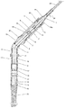
- FIG. 1 is a cross-sectional view of one embodiment of the plug in, re-usable wellhead penetrator.
- FIG. 1 shows a cross-sectional view of one embodiment of the claimed invention.
- An ESP cable 23 which can be either round or flat metal clad CLX cable, is preferably continuous from the ESP in the wellbore and is inserted into the down-hole side of a wellhead mandrel 16 .
- the wellhead mandrel 16 provides threads onto which is affixed a connection nipple 6 at the surface.
- the armored cable 23 is pre-stripped from each electrical conductor 19 (only two of the three normally found are shown in this view) in a length approximately one-half of the length of the mandrel 16 .
- Each leg of the three electrical conductors 19 is fed through a compressible rubber seal 10 fabricated from ethylene propylene diene monomer (EPDM), and inserted in a non-ferromagnetic guide 17 .
- the non-ferromagnetic guide 17 of this embodiment is made of brass coated with electroless nickel plating.
- An epoxy 18 is packed around each leg of the conductors 19 before they enter the rubber seal 10 and between the rubber seal 10 and the non-ferromagnetic guide 17 .
- the adapter nut or connection nipple 6 can be no larger than the outer diameter of the mandrel 16 itself.
- Epoxy 18 can be applied on the upper interior end of the mandrel. Epoxy 18 may be placed on each side of the rubber seal 10 or just on the down hole side of the rubber seal 10 .
- the non-ferromagnetic guide 17 is inserted on the interior of the mandrel 16 and retained there by offset coupling or connection nipple 6 .
- a mandrel lock nut could be screwed onto the threads shown on the mandrel 16 .
- the alternative placement of epoxy 18 on the interior of the mandrel covering both the end of the armored ESP cable supports the extending conductor coming through the armored cable 23 and the rubber seal 10 from rapid decompression.
- mandrel 16 Since the interior of mandrel 16 is intended to be coated with tetrafluoroethylene or other slick components, epoxy 18 can be readily removed from the mandrel 16 allowing its reuse as a wellhead penetrator.
- the entire assembly can also be packed with DC-4 or DC-11 silicone compound (both insulating products of Dow Corning) adding to the ease of removal while maintaining an insulated passage for the conductors through the wellhead.
- a surface cable 24 is inserted through a transition collar 1 and stripped of armoring.
- the armor-stripped surface conductors 24 a are further stripped of insulation and inserted into sockets 7 .
- the field-fabricated pigtail 20 can be fashioned from either flat or round ESP cable or CLX cable as available.
- the F-T-R (flat to round) transition collar 1 is packed with epoxy 18 providing a secure and insulated connection.
- Sockets 7 installed on the pig-tail conductors 24 a coming through the transition collar 1 can be either attached with set screws 15 or crimped on the stripped ends of each conductor.
- Each leg of the conductor 19 extending through the wellhead mandrel 16 is then inserted through a threaded nipple 13 which in turn is threadably attached to the wellhead nipple 6 on the wellhead side and through a union assembly 12 compressed against a second threaded nipple 13 .
- An elbow 11 of the needed degree depending on the wellhead clearance is then threaded onto the union assembly 12 .
- the electrical conductors 19 extending through the wellhead are inserted through an EPDM spacer 2 and into tubes 8 , carried within the insulator housing 4 restrained at its bottom by the vented insulator housing adapter 5 .
- Each of the insulated electrical conductors 19 extending through the wellhead (not shown in this view) is then stripped and an EDC connector pin 14 is attached to the stripped conductor 19 with set screws 15 .
- the installer will then insert the pins 14 into the prepared pigtail connectors 7 and move each into the insulator block or sleeve 3 .
- the vented insulator housing adapter 5 is threaded to the elbow.
- the sockets 7 are then covered by insulator block 3 .
- the transition collar 1 also provides a shoulder 21 that is formed by welding to a standard transition collar.
- a transition collar lock nut 22 is then threaded on the housing 4 retaining the conductors 24 a and insulator 3 .
- the housing 4 is further sealed to the elements by a vent hood 30 capping the vented insulator housing adapter 5 . Vent holes can be formed anywhere above the cable seal 10 to permit gas coming through the mandrel system to prevent migration down the surface cable 24 . Tightening the transition cable to housing lock nut 22 completes the installation.
Abstract
Description
Claims (20)
Priority Applications (1)
| Application Number | Priority Date | Filing Date | Title |
|---|---|---|---|
| US16/085,519 US11136847B2 (en) | 2016-03-15 | 2017-03-15 | Reusable field-attachable wellhead penetrator and method of assembly and use |
Applications Claiming Priority (3)
| Application Number | Priority Date | Filing Date | Title |
|---|---|---|---|
| US201662308649P | 2016-03-15 | 2016-03-15 | |
| PCT/US2017/022590 WO2017161048A2 (en) | 2016-03-15 | 2017-03-15 | Reusable field-attachable wellhead penetrator and method of assembly and use |
| US16/085,519 US11136847B2 (en) | 2016-03-15 | 2017-03-15 | Reusable field-attachable wellhead penetrator and method of assembly and use |
Publications (2)
| Publication Number | Publication Date |
|---|---|
| US20200291736A1 US20200291736A1 (en) | 2020-09-17 |
| US11136847B2 true US11136847B2 (en) | 2021-10-05 |
Family
ID=59850878
Family Applications (1)
| Application Number | Title | Priority Date | Filing Date |
|---|---|---|---|
| US16/085,519 Active 2037-11-30 US11136847B2 (en) | 2016-03-15 | 2017-03-15 | Reusable field-attachable wellhead penetrator and method of assembly and use |
Country Status (4)
| Country | Link |
|---|---|
| US (1) | US11136847B2 (en) |
| EP (1) | EP3430231A4 (en) |
| CA (1) | CA3016447A1 (en) |
| WO (1) | WO2017161048A2 (en) |
Families Citing this family (2)
| Publication number | Priority date | Publication date | Assignee | Title |
|---|---|---|---|---|
| GB201609468D0 (en) | 2016-05-30 | 2016-07-13 | Rmspumptools Ltd | Apparatus and method |
| CA3194654A1 (en) * | 2020-10-07 | 2022-04-14 | Innovex Downhole Solutions, Inc. | Wellhead penetrator for electrical connections |
Citations (14)
| Publication number | Priority date | Publication date | Assignee | Title |
|---|---|---|---|---|
| US3945700A (en) | 1974-08-06 | 1976-03-23 | Boston Insulated Wire & Cable Co. | Connector with fluid-resistant sleeve assembly |
| US4708201A (en) | 1984-10-29 | 1987-11-24 | Reed Lehman T | Top entry electrical transmission assembly for submersible pumping |
| US4728296A (en) * | 1986-09-05 | 1988-03-01 | Stamm Bradley C | Electrical adaptor for downhole submersible pump |
| WO1997039506A1 (en) | 1996-04-16 | 1997-10-23 | Moore Boyd B | Underground well electrical cable transition, seal and method |
| US20020070030A1 (en) * | 1999-12-08 | 2002-06-13 | Smith Leslie Dean | Wellhead with improved ESP cable pack-off and method |
| US6561268B2 (en) * | 2000-07-05 | 2003-05-13 | Tronic Limited | Connector |
| US6688386B2 (en) * | 2002-01-18 | 2004-02-10 | Stream-Flo Industries Ltd. | Tubing hanger and adapter assembly |
| US20080186155A1 (en) | 2005-02-04 | 2008-08-07 | Johnson Controls Technology Company | Persistence of Vision Display |
| US20100065302A1 (en) * | 2006-10-26 | 2010-03-18 | Romote Marine Systems Limited | Electrical connector with pressure seal |
| US20110017510A1 (en) | 2008-03-10 | 2011-01-27 | Quick Connectors, Inc. | Heater Cable to Pump Cable connector and Method of Installation |
| US8382508B1 (en) * | 2011-08-31 | 2013-02-26 | Baker Hughes Incorporated | High voltage mechanical splice connector |
| US20140110164A1 (en) | 2011-06-10 | 2014-04-24 | Quick Connectors, Inc. | System for continuous electrical well cable feed-through for a wellhead and method of installation |
| WO2014185958A1 (en) | 2013-05-14 | 2014-11-20 | Quick Connectors, Inc. | Disconnectable pressure-preserving electrical connector and method of installation |
| US20190119990A1 (en) * | 2015-10-19 | 2019-04-25 | Reelwell, A.S. | Wired pipe and method for making |
Family Cites Families (1)
| Publication number | Priority date | Publication date | Assignee | Title |
|---|---|---|---|---|
| CA2677346C (en) * | 2007-02-05 | 2014-03-18 | Quick Connectors Inc. | Down hole electrical connector for combating rapid decompression |
-
2017
- 2017-03-15 WO PCT/US2017/022590 patent/WO2017161048A2/en active Application Filing
- 2017-03-15 CA CA3016447A patent/CA3016447A1/en active Pending
- 2017-03-15 EP EP17767477.7A patent/EP3430231A4/en not_active Withdrawn
- 2017-03-15 US US16/085,519 patent/US11136847B2/en active Active
Patent Citations (14)
| Publication number | Priority date | Publication date | Assignee | Title |
|---|---|---|---|---|
| US3945700A (en) | 1974-08-06 | 1976-03-23 | Boston Insulated Wire & Cable Co. | Connector with fluid-resistant sleeve assembly |
| US4708201A (en) | 1984-10-29 | 1987-11-24 | Reed Lehman T | Top entry electrical transmission assembly for submersible pumping |
| US4728296A (en) * | 1986-09-05 | 1988-03-01 | Stamm Bradley C | Electrical adaptor for downhole submersible pump |
| WO1997039506A1 (en) | 1996-04-16 | 1997-10-23 | Moore Boyd B | Underground well electrical cable transition, seal and method |
| US20020070030A1 (en) * | 1999-12-08 | 2002-06-13 | Smith Leslie Dean | Wellhead with improved ESP cable pack-off and method |
| US6561268B2 (en) * | 2000-07-05 | 2003-05-13 | Tronic Limited | Connector |
| US6688386B2 (en) * | 2002-01-18 | 2004-02-10 | Stream-Flo Industries Ltd. | Tubing hanger and adapter assembly |
| US20080186155A1 (en) | 2005-02-04 | 2008-08-07 | Johnson Controls Technology Company | Persistence of Vision Display |
| US20100065302A1 (en) * | 2006-10-26 | 2010-03-18 | Romote Marine Systems Limited | Electrical connector with pressure seal |
| US20110017510A1 (en) | 2008-03-10 | 2011-01-27 | Quick Connectors, Inc. | Heater Cable to Pump Cable connector and Method of Installation |
| US20140110164A1 (en) | 2011-06-10 | 2014-04-24 | Quick Connectors, Inc. | System for continuous electrical well cable feed-through for a wellhead and method of installation |
| US8382508B1 (en) * | 2011-08-31 | 2013-02-26 | Baker Hughes Incorporated | High voltage mechanical splice connector |
| WO2014185958A1 (en) | 2013-05-14 | 2014-11-20 | Quick Connectors, Inc. | Disconnectable pressure-preserving electrical connector and method of installation |
| US20190119990A1 (en) * | 2015-10-19 | 2019-04-25 | Reelwell, A.S. | Wired pipe and method for making |
Non-Patent Citations (2)
| Title |
|---|
| Extended European Search Report dated Feb. 13, 2020, EP Application No. 17767477, pp. 1-12. |
| Ivan Kecman, Partial Supplementary European Search Report dated Oct. 14, 2019, EP Application No. 17167477.7, pp. 1-14. |
Also Published As
| Publication number | Publication date |
|---|---|
| US20200291736A1 (en) | 2020-09-17 |
| WO2017161048A2 (en) | 2017-09-21 |
| EP3430231A2 (en) | 2019-01-23 |
| EP3430231A4 (en) | 2020-03-18 |
| WO2017161048A3 (en) | 2018-07-26 |
| CA3016447A1 (en) | 2017-09-21 |
Similar Documents
| Publication | Publication Date | Title |
|---|---|---|
| EP2082454B1 (en) | Splice for down hole electrical submersible pump cable | |
| US11781396B2 (en) | Disconnectable pressure-preserving electrical connector and method of installation | |
| CA2826753C (en) | Cable connection system | |
| US7980873B2 (en) | Electrical connector for insulated conductive wires encapsulated in protective tubing | |
| US3945700A (en) | Connector with fluid-resistant sleeve assembly | |
| EP2989284B1 (en) | Orthogonal electrical connector penetrator system for a coiled tubing electrical service in a flow-through multi-bowl wellhead and method of installation and use | |
| CN109031568B (en) | Branching device for submarine cable connection | |
| US8502075B2 (en) | Heater cable to pump cable connector and method of installation | |
| US11136847B2 (en) | Reusable field-attachable wellhead penetrator and method of assembly and use | |
| US10689917B2 (en) | Simplified packer penetrator and method of installation | |
| RU179962U1 (en) | Device for current supply to the electric drill while drilling wells | |
| US10851606B2 (en) | Subsea flying lead | |
| RU194596U1 (en) | PACKER SLEEVE WITH CABLE INPUT | |
| US20210372234A1 (en) | Explosive environment termination of wellhead cables | |
| RU2610965C1 (en) | Load bearing sleeve for submersible rig | |
| US20170005428A1 (en) | Connector for wellhead |
Legal Events
| Date | Code | Title | Description |
|---|---|---|---|
| FEPP | Fee payment procedure |
Free format text: ENTITY STATUS SET TO UNDISCOUNTED (ORIGINAL EVENT CODE: BIG.); ENTITY STATUS OF PATENT OWNER: LARGE ENTITY |
|
| AS | Assignment |
Owner name: QUICK CONNECTORS, INC., TEXAS Free format text: ASSIGNMENT OF ASSIGNORS INTEREST;ASSIGNOR:EMERSON, TOD D;REEL/FRAME:047900/0192 Effective date: 20180406 |
|
| FEPP | Fee payment procedure |
Free format text: ENTITY STATUS SET TO SMALL (ORIGINAL EVENT CODE: SMAL); ENTITY STATUS OF PATENT OWNER: LARGE ENTITY |
|
| AS | Assignment |
Owner name: PNC BANK, NATIONAL ASSOCIATION, AS AGENT, PENNSYLVANIA Free format text: AMENDED AND RESTATED TRADEMARK AND PATENT SECURITY AGREEMENT;ASSIGNORS:INNOVEX DOWNHOLE SOLUTIONS, INC.;INNOVEX ENERSERVE ASSETCO, LLC;QUICK CONNECTORS, INC.;REEL/FRAME:049454/0374 Effective date: 20190610 |
|
| FEPP | Fee payment procedure |
Free format text: ENTITY STATUS SET TO UNDISCOUNTED (ORIGINAL EVENT CODE: BIG.); ENTITY STATUS OF PATENT OWNER: LARGE ENTITY |
|
| STPP | Information on status: patent application and granting procedure in general |
Free format text: FINAL REJECTION MAILED |
|
| STPP | Information on status: patent application and granting procedure in general |
Free format text: RESPONSE AFTER FINAL ACTION FORWARDED TO EXAMINER |
|
| STPP | Information on status: patent application and granting procedure in general |
Free format text: RESPONSE AFTER FINAL ACTION FORWARDED TO EXAMINER |
|
| STPP | Information on status: patent application and granting procedure in general |
Free format text: RESPONSE AFTER FINAL ACTION FORWARDED TO EXAMINER |
|
| STPP | Information on status: patent application and granting procedure in general |
Free format text: NOTICE OF ALLOWANCE MAILED -- APPLICATION RECEIVED IN OFFICE OF PUBLICATIONS |
|
| STPP | Information on status: patent application and granting procedure in general |
Free format text: PUBLICATIONS -- ISSUE FEE PAYMENT VERIFIED |
|
| STCF | Information on status: patent grant |
Free format text: PATENTED CASE |
|
| AS | Assignment |
Owner name: PNC BANK, NATIONAL ASSOCIATION, PENNSYLVANIA Free format text: AFFIRMATION OF ASSIGNMENT OF INTELLECTUAL PROPERTY;ASSIGNOR:INNOVEX DOWNHOLE SOLUTIONS, INC.;REEL/FRAME:060377/0585 Effective date: 20220610 |
|
| AS | Assignment |
Owner name: PNC BANK, NATIONAL ASSOCIATION, PENNSYLVANIA Free format text: SECOND AMENDED AND RESTATED TRADEMARK AND PATENT SECURITY AGREEMENT;ASSIGNORS:INNOVEX DOWNHOLE SOLUTIONS, INC.;TERCEL OILFIELD PRODUCTS USA L.L.C.;TOP-CO INC.;REEL/FRAME:060438/0932 Effective date: 20220610 |