US11135849B2 - Liquid ejecting apparatus and maintenance method of liquid ejecting apparatus - Google Patents
Liquid ejecting apparatus and maintenance method of liquid ejecting apparatus Download PDFInfo
- Publication number
- US11135849B2 US11135849B2 US16/505,380 US201916505380A US11135849B2 US 11135849 B2 US11135849 B2 US 11135849B2 US 201916505380 A US201916505380 A US 201916505380A US 11135849 B2 US11135849 B2 US 11135849B2
- Authority
- US
- United States
- Prior art keywords
- liquid
- wiping
- nozzle
- ejector
- ejecting apparatus
- Prior art date
- Legal status (The legal status is an assumption and is not a legal conclusion. Google has not performed a legal analysis and makes no representation as to the accuracy of the status listed.)
- Active, expires
Links
- 239000007788 liquid Substances 0.000 title claims abstract description 1350
- 238000012423 maintenance Methods 0.000 title claims description 75
- 238000000034 method Methods 0.000 title claims description 70
- 230000007246 mechanism Effects 0.000 claims abstract description 170
- 230000008859 change Effects 0.000 claims abstract description 47
- 238000012545 processing Methods 0.000 claims description 48
- 238000001514 detection method Methods 0.000 claims description 24
- 230000002159 abnormal effect Effects 0.000 claims description 22
- 239000000976 ink Substances 0.000 description 223
- 239000012530 fluid Substances 0.000 description 167
- 239000000203 mixture Substances 0.000 description 122
- 239000000758 substrate Substances 0.000 description 106
- 229920005989 resin Polymers 0.000 description 105
- 239000011347 resin Substances 0.000 description 105
- 238000011144 upstream manufacturing Methods 0.000 description 104
- 230000032258 transport Effects 0.000 description 98
- 239000000049 pigment Substances 0.000 description 86
- 239000004744 fabric Substances 0.000 description 85
- 239000004094 surface-active agent Substances 0.000 description 82
- -1 zirconium Chemical compound 0.000 description 76
- 238000005406 washing Methods 0.000 description 61
- 239000002585 base Substances 0.000 description 53
- PEDCQBHIVMGVHV-UHFFFAOYSA-N Glycerine Chemical compound OCC(O)CO PEDCQBHIVMGVHV-UHFFFAOYSA-N 0.000 description 48
- 238000004891 communication Methods 0.000 description 48
- 239000010408 film Substances 0.000 description 40
- 239000000463 material Substances 0.000 description 38
- 238000004804 winding Methods 0.000 description 38
- 239000000839 emulsion Substances 0.000 description 36
- 239000001023 inorganic pigment Substances 0.000 description 35
- 230000005484 gravity Effects 0.000 description 33
- 239000001993 wax Substances 0.000 description 33
- 238000011010 flushing procedure Methods 0.000 description 31
- 239000002245 particle Substances 0.000 description 31
- 239000007789 gas Substances 0.000 description 30
- 238000005470 impregnation Methods 0.000 description 30
- 238000004140 cleaning Methods 0.000 description 27
- 239000002699 waste material Substances 0.000 description 27
- XLYOFNOQVPJJNP-UHFFFAOYSA-N water Substances O XLYOFNOQVPJJNP-UHFFFAOYSA-N 0.000 description 26
- 235000011187 glycerol Nutrition 0.000 description 24
- 238000003860 storage Methods 0.000 description 24
- 238000002156 mixing Methods 0.000 description 21
- 238000003825 pressing Methods 0.000 description 21
- 230000005540 biological transmission Effects 0.000 description 20
- 230000000903 blocking effect Effects 0.000 description 20
- 238000010438 heat treatment Methods 0.000 description 20
- LYCAIKOWRPUZTN-UHFFFAOYSA-N Ethylene glycol Chemical compound OCCO LYCAIKOWRPUZTN-UHFFFAOYSA-N 0.000 description 19
- 230000008878 coupling Effects 0.000 description 19
- 238000010168 coupling process Methods 0.000 description 19
- 238000005859 coupling reaction Methods 0.000 description 19
- GWEVSGVZZGPLCZ-UHFFFAOYSA-N Titan oxide Chemical compound O=[Ti]=O GWEVSGVZZGPLCZ-UHFFFAOYSA-N 0.000 description 18
- 230000015572 biosynthetic process Effects 0.000 description 18
- 229920001577 copolymer Polymers 0.000 description 18
- 239000012298 atmosphere Substances 0.000 description 17
- 238000003780 insertion Methods 0.000 description 17
- 230000037431 insertion Effects 0.000 description 17
- 239000002736 nonionic surfactant Substances 0.000 description 17
- 239000013530 defoamer Substances 0.000 description 16
- 230000001681 protective effect Effects 0.000 description 16
- XUIMIQQOPSSXEZ-UHFFFAOYSA-N Silicon Chemical compound [Si] XUIMIQQOPSSXEZ-UHFFFAOYSA-N 0.000 description 15
- 239000010703 silicon Substances 0.000 description 15
- 229910052710 silicon Inorganic materials 0.000 description 15
- YCKRFDGAMUMZLT-UHFFFAOYSA-N Fluorine atom Chemical compound [F] YCKRFDGAMUMZLT-UHFFFAOYSA-N 0.000 description 14
- 229920001971 elastomer Polymers 0.000 description 14
- 239000011737 fluorine Substances 0.000 description 14
- 229910052731 fluorine Inorganic materials 0.000 description 14
- 229910052751 metal Inorganic materials 0.000 description 14
- 239000002184 metal Substances 0.000 description 14
- 230000002940 repellent Effects 0.000 description 14
- 239000005871 repellent Substances 0.000 description 14
- 239000004909 Moisturizer Substances 0.000 description 13
- 238000005299 abrasion Methods 0.000 description 13
- 238000004040 coloring Methods 0.000 description 13
- WGCNASOHLSPBMP-UHFFFAOYSA-N hydroxyacetaldehyde Natural products OCC=O WGCNASOHLSPBMP-UHFFFAOYSA-N 0.000 description 13
- 230000001333 moisturizer Effects 0.000 description 13
- 239000003960 organic solvent Substances 0.000 description 13
- 239000005060 rubber Substances 0.000 description 13
- 239000004698 Polyethylene Substances 0.000 description 12
- 150000001875 compounds Chemical class 0.000 description 12
- 238000010586 diagram Methods 0.000 description 12
- 230000000694 effects Effects 0.000 description 12
- 229920000573 polyethylene Polymers 0.000 description 12
- 238000004321 preservation Methods 0.000 description 12
- 238000007789 sealing Methods 0.000 description 12
- 239000000126 substance Substances 0.000 description 12
- 229920003171 Poly (ethylene oxide) Polymers 0.000 description 11
- VYPSYNLAJGMNEJ-UHFFFAOYSA-N Silicium dioxide Chemical compound O=[Si]=O VYPSYNLAJGMNEJ-UHFFFAOYSA-N 0.000 description 11
- HSFWRNGVRCDJHI-UHFFFAOYSA-N alpha-acetylene Natural products C#C HSFWRNGVRCDJHI-UHFFFAOYSA-N 0.000 description 11
- 230000002421 anti-septic effect Effects 0.000 description 11
- 238000009835 boiling Methods 0.000 description 11
- 239000002250 absorbent Substances 0.000 description 10
- 230000002745 absorbent Effects 0.000 description 10
- 230000004308 accommodation Effects 0.000 description 10
- 238000011109 contamination Methods 0.000 description 10
- 239000006260 foam Substances 0.000 description 10
- 238000005187 foaming Methods 0.000 description 10
- 229910052500 inorganic mineral Inorganic materials 0.000 description 10
- 239000011707 mineral Substances 0.000 description 10
- 150000005215 alkyl ethers Chemical class 0.000 description 9
- 125000004432 carbon atom Chemical group C* 0.000 description 9
- 239000013065 commercial product Substances 0.000 description 9
- 238000001914 filtration Methods 0.000 description 9
- 239000000047 product Substances 0.000 description 9
- OGIDPMRJRNCKJF-UHFFFAOYSA-N titanium oxide Inorganic materials [Ti]=O OGIDPMRJRNCKJF-UHFFFAOYSA-N 0.000 description 9
- 239000000975 dye Substances 0.000 description 8
- 230000005499 meniscus Effects 0.000 description 8
- 230000004048 modification Effects 0.000 description 8
- 238000012986 modification Methods 0.000 description 8
- 239000012860 organic pigment Substances 0.000 description 8
- 230000000149 penetrating effect Effects 0.000 description 8
- 229920000642 polymer Polymers 0.000 description 8
- 229910001220 stainless steel Inorganic materials 0.000 description 8
- 239000010935 stainless steel Substances 0.000 description 8
- DNIAPMSPPWPWGF-UHFFFAOYSA-N Propylene glycol Chemical compound CC(O)CO DNIAPMSPPWPWGF-UHFFFAOYSA-N 0.000 description 7
- 239000003795 chemical substances by application Substances 0.000 description 7
- KPUWHANPEXNPJT-UHFFFAOYSA-N disiloxane Chemical class [SiH3]O[SiH3] KPUWHANPEXNPJT-UHFFFAOYSA-N 0.000 description 7
- 238000010979 pH adjustment Methods 0.000 description 7
- PDEDQSAFHNADLV-UHFFFAOYSA-M potassium;disodium;dinitrate;nitrite Chemical compound [Na+].[Na+].[K+].[O-]N=O.[O-][N+]([O-])=O.[O-][N+]([O-])=O PDEDQSAFHNADLV-UHFFFAOYSA-M 0.000 description 7
- 239000002904 solvent Substances 0.000 description 7
- UQSXHKLRYXJYBZ-UHFFFAOYSA-N Iron oxide Chemical compound [Fe]=O UQSXHKLRYXJYBZ-UHFFFAOYSA-N 0.000 description 6
- KFZMGEQAYNKOFK-UHFFFAOYSA-N Isopropanol Chemical compound CC(C)O KFZMGEQAYNKOFK-UHFFFAOYSA-N 0.000 description 6
- ZMXDDKWLCZADIW-UHFFFAOYSA-N N,N-Dimethylformamide Chemical compound CN(C)C=O ZMXDDKWLCZADIW-UHFFFAOYSA-N 0.000 description 6
- PXHVJJICTQNCMI-UHFFFAOYSA-N Nickel Chemical compound [Ni] PXHVJJICTQNCMI-UHFFFAOYSA-N 0.000 description 6
- XLOMVQKBTHCTTD-UHFFFAOYSA-N Zinc monoxide Chemical compound [Zn]=O XLOMVQKBTHCTTD-UHFFFAOYSA-N 0.000 description 6
- 239000013078 crystal Substances 0.000 description 6
- MTHSVFCYNBDYFN-UHFFFAOYSA-N diethylene glycol Chemical compound OCCOCCO MTHSVFCYNBDYFN-UHFFFAOYSA-N 0.000 description 6
- 239000002270 dispersing agent Substances 0.000 description 6
- 238000009826 distribution Methods 0.000 description 6
- 230000006870 function Effects 0.000 description 6
- 125000002496 methyl group Chemical group [H]C([H])([H])* 0.000 description 6
- 239000002798 polar solvent Substances 0.000 description 6
- 229920001451 polypropylene glycol Polymers 0.000 description 6
- 238000007790 scraping Methods 0.000 description 6
- 239000007787 solid Substances 0.000 description 6
- 238000007711 solidification Methods 0.000 description 6
- 230000008023 solidification Effects 0.000 description 6
- LFQSCWFLJHTTHZ-UHFFFAOYSA-N Ethanol Chemical compound CCO LFQSCWFLJHTTHZ-UHFFFAOYSA-N 0.000 description 5
- 230000009471 action Effects 0.000 description 5
- 125000000217 alkyl group Chemical group 0.000 description 5
- 229920001400 block copolymer Polymers 0.000 description 5
- 229910052799 carbon Inorganic materials 0.000 description 5
- 239000006185 dispersion Substances 0.000 description 5
- 125000004435 hydrogen atom Chemical group [H]* 0.000 description 5
- YPFDHNVEDLHUCE-UHFFFAOYSA-N propane-1,3-diol Chemical compound OCCCO YPFDHNVEDLHUCE-UHFFFAOYSA-N 0.000 description 5
- 230000002441 reversible effect Effects 0.000 description 5
- FEIQOMCWGDNMHM-UHFFFAOYSA-N 5-phenylpenta-2,4-dienoic acid Chemical compound OC(=O)C=CC=CC1=CC=CC=C1 FEIQOMCWGDNMHM-UHFFFAOYSA-N 0.000 description 4
- IAZDPXIOMUYVGZ-UHFFFAOYSA-N Dimethylsulphoxide Chemical compound CS(C)=O IAZDPXIOMUYVGZ-UHFFFAOYSA-N 0.000 description 4
- CERQOIWHTDAKMF-UHFFFAOYSA-N Methacrylic acid Chemical compound CC(=C)C(O)=O CERQOIWHTDAKMF-UHFFFAOYSA-N 0.000 description 4
- SECXISVLQFMRJM-UHFFFAOYSA-N N-Methylpyrrolidone Chemical compound CN1CCCC1=O SECXISVLQFMRJM-UHFFFAOYSA-N 0.000 description 4
- 229920002845 Poly(methacrylic acid) Polymers 0.000 description 4
- 239000004721 Polyphenylene oxide Substances 0.000 description 4
- PPBRXRYQALVLMV-UHFFFAOYSA-N Styrene Chemical compound C=CC1=CC=CC=C1 PPBRXRYQALVLMV-UHFFFAOYSA-N 0.000 description 4
- XTXRWKRVRITETP-UHFFFAOYSA-N Vinyl acetate Chemical compound CC(=O)OC=C XTXRWKRVRITETP-UHFFFAOYSA-N 0.000 description 4
- 239000011358 absorbing material Substances 0.000 description 4
- 239000000654 additive Substances 0.000 description 4
- 239000000853 adhesive Substances 0.000 description 4
- 230000001070 adhesive effect Effects 0.000 description 4
- TZCXTZWJZNENPQ-UHFFFAOYSA-L barium sulfate Chemical compound [Ba+2].[O-]S([O-])(=O)=O TZCXTZWJZNENPQ-UHFFFAOYSA-L 0.000 description 4
- 239000011230 binding agent Substances 0.000 description 4
- 239000011575 calcium Substances 0.000 description 4
- 229920006026 co-polymeric resin Polymers 0.000 description 4
- 238000001035 drying Methods 0.000 description 4
- 230000002349 favourable effect Effects 0.000 description 4
- 235000019239 indanthrene blue RS Nutrition 0.000 description 4
- UHOKSCJSTAHBSO-UHFFFAOYSA-N indanthrone blue Chemical compound C1=CC=C2C(=O)C3=CC=C4NC5=C6C(=O)C7=CC=CC=C7C(=O)C6=CC=C5NC4=C3C(=O)C2=C1 UHOKSCJSTAHBSO-UHFFFAOYSA-N 0.000 description 4
- 229920000570 polyether Polymers 0.000 description 4
- 229920000098 polyolefin Polymers 0.000 description 4
- 229920001296 polysiloxane Polymers 0.000 description 4
- 229920002451 polyvinyl alcohol Polymers 0.000 description 4
- 230000008569 process Effects 0.000 description 4
- 229910052814 silicon oxide Inorganic materials 0.000 description 4
- 238000003892 spreading Methods 0.000 description 4
- 230000007480 spreading Effects 0.000 description 4
- HXJUTPCZVOIRIF-UHFFFAOYSA-N sulfolane Chemical class O=S1(=O)CCCC1 HXJUTPCZVOIRIF-UHFFFAOYSA-N 0.000 description 4
- ZUHZGEOKBKGPSW-UHFFFAOYSA-N tetraglyme Chemical compound COCCOCCOCCOCCOC ZUHZGEOKBKGPSW-UHFFFAOYSA-N 0.000 description 4
- 229920002554 vinyl polymer Polymers 0.000 description 4
- JNYAEWCLZODPBN-JGWLITMVSA-N (2r,3r,4s)-2-[(1r)-1,2-dihydroxyethyl]oxolane-3,4-diol Chemical class OC[C@@H](O)[C@H]1OC[C@H](O)[C@H]1O JNYAEWCLZODPBN-JGWLITMVSA-N 0.000 description 3
- 229920000178 Acrylic resin Polymers 0.000 description 3
- 239000004925 Acrylic resin Substances 0.000 description 3
- IAYPIBMASNFSPL-UHFFFAOYSA-N Ethylene oxide Chemical compound C1CO1 IAYPIBMASNFSPL-UHFFFAOYSA-N 0.000 description 3
- CPLXHLVBOLITMK-UHFFFAOYSA-N Magnesium oxide Chemical compound [Mg]=O CPLXHLVBOLITMK-UHFFFAOYSA-N 0.000 description 3
- OKKJLVBELUTLKV-UHFFFAOYSA-N Methanol Chemical compound OC OKKJLVBELUTLKV-UHFFFAOYSA-N 0.000 description 3
- ALQSHHUCVQOPAS-UHFFFAOYSA-N Pentane-1,5-diol Chemical compound OCCCCCO ALQSHHUCVQOPAS-UHFFFAOYSA-N 0.000 description 3
- KWYUFKZDYYNOTN-UHFFFAOYSA-M Potassium hydroxide Chemical compound [OH-].[K+] KWYUFKZDYYNOTN-UHFFFAOYSA-M 0.000 description 3
- HEMHJVSKTPXQMS-UHFFFAOYSA-M Sodium hydroxide Chemical compound [OH-].[Na+] HEMHJVSKTPXQMS-UHFFFAOYSA-M 0.000 description 3
- BZHJMEDXRYGGRV-UHFFFAOYSA-N Vinyl chloride Chemical compound ClC=C BZHJMEDXRYGGRV-UHFFFAOYSA-N 0.000 description 3
- ZUQAPLKKNAQJAU-UHFFFAOYSA-N acetylenediol Chemical compound OC#CO ZUQAPLKKNAQJAU-UHFFFAOYSA-N 0.000 description 3
- 230000002378 acidificating effect Effects 0.000 description 3
- 229910052782 aluminium Inorganic materials 0.000 description 3
- XAGFODPZIPBFFR-UHFFFAOYSA-N aluminium Chemical compound [Al] XAGFODPZIPBFFR-UHFFFAOYSA-N 0.000 description 3
- PNEYBMLMFCGWSK-UHFFFAOYSA-N aluminium oxide Inorganic materials [O-2].[O-2].[O-2].[Al+3].[Al+3] PNEYBMLMFCGWSK-UHFFFAOYSA-N 0.000 description 3
- 239000003945 anionic surfactant Substances 0.000 description 3
- DMSMPAJRVJJAGA-UHFFFAOYSA-N benzo[d]isothiazol-3-one Chemical compound C1=CC=C2C(=O)NSC2=C1 DMSMPAJRVJJAGA-UHFFFAOYSA-N 0.000 description 3
- 230000000740 bleeding effect Effects 0.000 description 3
- BTANRVKWQNVYAZ-UHFFFAOYSA-N butan-2-ol Chemical compound CCC(C)O BTANRVKWQNVYAZ-UHFFFAOYSA-N 0.000 description 3
- WUKWITHWXAAZEY-UHFFFAOYSA-L calcium difluoride Chemical compound [F-].[F-].[Ca+2] WUKWITHWXAAZEY-UHFFFAOYSA-L 0.000 description 3
- 235000014113 dietary fatty acids Nutrition 0.000 description 3
- USIUVYZYUHIAEV-UHFFFAOYSA-N diphenyl ether Chemical compound C=1C=CC=CC=1OC1=CC=CC=C1 USIUVYZYUHIAEV-UHFFFAOYSA-N 0.000 description 3
- 238000006073 displacement reaction Methods 0.000 description 3
- 239000000194 fatty acid Substances 0.000 description 3
- 229930195729 fatty acid Natural products 0.000 description 3
- 239000010436 fluorite Substances 0.000 description 3
- 230000009477 glass transition Effects 0.000 description 3
- 229910052736 halogen Inorganic materials 0.000 description 3
- 150000002367 halogens Chemical class 0.000 description 3
- 150000002430 hydrocarbons Chemical group 0.000 description 3
- 238000009413 insulation Methods 0.000 description 3
- 150000002596 lactones Chemical class 0.000 description 3
- 230000003020 moisturizing effect Effects 0.000 description 3
- 229910052759 nickel Inorganic materials 0.000 description 3
- 125000005375 organosiloxane group Chemical group 0.000 description 3
- TWNQGVIAIRXVLR-UHFFFAOYSA-N oxo(oxoalumanyloxy)alumane Chemical compound O=[Al]O[Al]=O TWNQGVIAIRXVLR-UHFFFAOYSA-N 0.000 description 3
- RVTZCBVAJQQJTK-UHFFFAOYSA-N oxygen(2-);zirconium(4+) Chemical compound [O-2].[O-2].[Zr+4] RVTZCBVAJQQJTK-UHFFFAOYSA-N 0.000 description 3
- 125000003367 polycyclic group Chemical group 0.000 description 3
- 239000000843 powder Substances 0.000 description 3
- 238000007639 printing Methods 0.000 description 3
- HNJBEVLQSNELDL-UHFFFAOYSA-N pyrrolidin-2-one Chemical compound O=C1CCCN1 HNJBEVLQSNELDL-UHFFFAOYSA-N 0.000 description 3
- 150000004040 pyrrolidinones Chemical class 0.000 description 3
- 239000000377 silicon dioxide Substances 0.000 description 3
- 150000003462 sulfoxides Chemical class 0.000 description 3
- 238000010408 sweeping Methods 0.000 description 3
- 229920005992 thermoplastic resin Polymers 0.000 description 3
- 230000008719 thickening Effects 0.000 description 3
- 239000010409 thin film Substances 0.000 description 3
- 239000011787 zinc oxide Substances 0.000 description 3
- 229910001928 zirconium oxide Inorganic materials 0.000 description 3
- QYGBYAQGBVHMDD-XQRVVYSFSA-N (z)-2-cyano-3-thiophen-2-ylprop-2-enoic acid Chemical compound OC(=O)C(\C#N)=C/C1=CC=CS1 QYGBYAQGBVHMDD-XQRVVYSFSA-N 0.000 description 2
- AVQQQNCBBIEMEU-UHFFFAOYSA-N 1,1,3,3-tetramethylurea Chemical compound CN(C)C(=O)N(C)C AVQQQNCBBIEMEU-UHFFFAOYSA-N 0.000 description 2
- 229940015975 1,2-hexanediol Drugs 0.000 description 2
- CYSGHNMQYZDMIA-UHFFFAOYSA-N 1,3-Dimethyl-2-imidazolidinon Chemical compound CN1CCN(C)C1=O CYSGHNMQYZDMIA-UHFFFAOYSA-N 0.000 description 2
- HYLLZXPMJRMUHH-UHFFFAOYSA-N 1-[2-(2-methoxyethoxy)ethoxy]butane Chemical compound CCCCOCCOCCOC HYLLZXPMJRMUHH-UHFFFAOYSA-N 0.000 description 2
- KPAPHODVWOVUJL-UHFFFAOYSA-N 1-benzofuran;1h-indene Chemical compound C1=CC=C2CC=CC2=C1.C1=CC=C2OC=CC2=C1 KPAPHODVWOVUJL-UHFFFAOYSA-N 0.000 description 2
- OSSNTDFYBPYIEC-UHFFFAOYSA-N 1-ethenylimidazole Chemical compound C=CN1C=CN=C1 OSSNTDFYBPYIEC-UHFFFAOYSA-N 0.000 description 2
- RRQYJINTUHWNHW-UHFFFAOYSA-N 1-ethoxy-2-(2-ethoxyethoxy)ethane Chemical compound CCOCCOCCOCC RRQYJINTUHWNHW-UHFFFAOYSA-N 0.000 description 2
- ZIKLJUUTSQYGQI-UHFFFAOYSA-N 1-ethoxy-2-(2-ethoxypropoxy)propane Chemical compound CCOCC(C)OCC(C)OCC ZIKLJUUTSQYGQI-UHFFFAOYSA-N 0.000 description 2
- JOLQKTGDSGKSKJ-UHFFFAOYSA-N 1-ethoxypropan-2-ol Chemical compound CCOCC(C)O JOLQKTGDSGKSKJ-UHFFFAOYSA-N 0.000 description 2
- RERATEUBWLKDFE-UHFFFAOYSA-N 1-methoxy-2-[2-(2-methoxypropoxy)propoxy]propane Chemical compound COCC(C)OCC(C)OCC(C)OC RERATEUBWLKDFE-UHFFFAOYSA-N 0.000 description 2
- ARXJGSRGQADJSQ-UHFFFAOYSA-N 1-methoxypropan-2-ol Chemical compound COCC(C)O ARXJGSRGQADJSQ-UHFFFAOYSA-N 0.000 description 2
- FENFUOGYJVOCRY-UHFFFAOYSA-N 1-propoxypropan-2-ol Chemical compound CCCOCC(C)O FENFUOGYJVOCRY-UHFFFAOYSA-N 0.000 description 2
- GQCZPFJGIXHZMB-UHFFFAOYSA-N 1-tert-Butoxy-2-propanol Chemical compound CC(O)COC(C)(C)C GQCZPFJGIXHZMB-UHFFFAOYSA-N 0.000 description 2
- OAYXUHPQHDHDDZ-UHFFFAOYSA-N 2-(2-butoxyethoxy)ethanol Chemical compound CCCCOCCOCCO OAYXUHPQHDHDDZ-UHFFFAOYSA-N 0.000 description 2
- WMDZKDKPYCNCDZ-UHFFFAOYSA-N 2-(2-butoxypropoxy)propan-1-ol Chemical compound CCCCOC(C)COC(C)CO WMDZKDKPYCNCDZ-UHFFFAOYSA-N 0.000 description 2
- ZUAURMBNZUCEAF-UHFFFAOYSA-N 2-(2-phenoxyethoxy)ethanol Chemical compound OCCOCCOC1=CC=CC=C1 ZUAURMBNZUCEAF-UHFFFAOYSA-N 0.000 description 2
- HUFRRBHGGJPNGG-UHFFFAOYSA-N 2-(2-propan-2-yloxypropoxy)propan-1-ol Chemical compound CC(C)OC(C)COC(C)CO HUFRRBHGGJPNGG-UHFFFAOYSA-N 0.000 description 2
- XYVAYAJYLWYJJN-UHFFFAOYSA-N 2-(2-propoxypropoxy)propan-1-ol Chemical compound CCCOC(C)COC(C)CO XYVAYAJYLWYJJN-UHFFFAOYSA-N 0.000 description 2
- OEPOKWHJYJXUGD-UHFFFAOYSA-N 2-(3-phenylmethoxyphenyl)-1,3-thiazole-4-carbaldehyde Chemical compound O=CC1=CSC(C=2C=C(OCC=3C=CC=CC=3)C=CC=2)=N1 OEPOKWHJYJXUGD-UHFFFAOYSA-N 0.000 description 2
- RWLALWYNXFYRGW-UHFFFAOYSA-N 2-Ethyl-1,3-hexanediol Chemical compound CCCC(O)C(CC)CO RWLALWYNXFYRGW-UHFFFAOYSA-N 0.000 description 2
- BDLXTDLGTWNUFM-UHFFFAOYSA-N 2-[(2-methylpropan-2-yl)oxy]ethanol Chemical compound CC(C)(C)OCCO BDLXTDLGTWNUFM-UHFFFAOYSA-N 0.000 description 2
- COBPKKZHLDDMTB-UHFFFAOYSA-N 2-[2-(2-butoxyethoxy)ethoxy]ethanol Chemical compound CCCCOCCOCCOCCO COBPKKZHLDDMTB-UHFFFAOYSA-N 0.000 description 2
- GICQWELXXKHZIN-UHFFFAOYSA-N 2-[2-[(2-methylpropan-2-yl)oxy]ethoxy]ethanol Chemical compound CC(C)(C)OCCOCCO GICQWELXXKHZIN-UHFFFAOYSA-N 0.000 description 2
- POAOYUHQDCAZBD-UHFFFAOYSA-N 2-butoxyethanol Chemical compound CCCCOCCO POAOYUHQDCAZBD-UHFFFAOYSA-N 0.000 description 2
- CRWNQZTZTZWPOF-UHFFFAOYSA-N 2-methyl-4-phenylpyridine Chemical compound C1=NC(C)=CC(C=2C=CC=CC=2)=C1 CRWNQZTZTZWPOF-UHFFFAOYSA-N 0.000 description 2
- SVTBMSDMJJWYQN-UHFFFAOYSA-N 2-methylpentane-2,4-diol Chemical compound CC(O)CC(C)(C)O SVTBMSDMJJWYQN-UHFFFAOYSA-N 0.000 description 2
- KGIGUEBEKRSTEW-UHFFFAOYSA-N 2-vinylpyridine Chemical compound C=CC1=CC=CC=N1 KGIGUEBEKRSTEW-UHFFFAOYSA-N 0.000 description 2
- NTKBNCABAMQDIG-UHFFFAOYSA-N 3-butoxypropan-1-ol Chemical compound CCCCOCCCO NTKBNCABAMQDIG-UHFFFAOYSA-N 0.000 description 2
- VATRWWPJWVCZTA-UHFFFAOYSA-N 3-oxo-n-[2-(trifluoromethyl)phenyl]butanamide Chemical compound CC(=O)CC(=O)NC1=CC=CC=C1C(F)(F)F VATRWWPJWVCZTA-UHFFFAOYSA-N 0.000 description 2
- GBSGXZBOFKJGMG-UHFFFAOYSA-N 3-propan-2-yloxypropan-1-ol Chemical compound CC(C)OCCCO GBSGXZBOFKJGMG-UHFFFAOYSA-N 0.000 description 2
- YEJRWHAVMIAJKC-UHFFFAOYSA-N 4-Butyrolactone Chemical compound O=C1CCCO1 YEJRWHAVMIAJKC-UHFFFAOYSA-N 0.000 description 2
- KSLLMGLKCVSKFF-UHFFFAOYSA-N 5,12-dihydroquinolino[2,3-b]acridine-6,7,13,14-tetrone Chemical compound N1C2=CC=CC=C2C(=O)C2=C1C(=O)C(C(=O)C1=CC=CC=C1N1)=C1C2=O KSLLMGLKCVSKFF-UHFFFAOYSA-N 0.000 description 2
- HRPVXLWXLXDGHG-UHFFFAOYSA-N Acrylamide Chemical compound NC(=O)C=C HRPVXLWXLXDGHG-UHFFFAOYSA-N 0.000 description 2
- NLHHRLWOUZZQLW-UHFFFAOYSA-N Acrylonitrile Chemical compound C=CC#N NLHHRLWOUZZQLW-UHFFFAOYSA-N 0.000 description 2
- QGZKDVFQNNGYKY-UHFFFAOYSA-N Ammonia Chemical compound N QGZKDVFQNNGYKY-UHFFFAOYSA-N 0.000 description 2
- KWIUHFFTVRNATP-UHFFFAOYSA-N Betaine Natural products C[N+](C)(C)CC([O-])=O KWIUHFFTVRNATP-UHFFFAOYSA-N 0.000 description 2
- 229910021532 Calcite Inorganic materials 0.000 description 2
- VTYYLEPIZMXCLO-UHFFFAOYSA-L Calcium carbonate Chemical compound [Ca+2].[O-]C([O-])=O VTYYLEPIZMXCLO-UHFFFAOYSA-L 0.000 description 2
- 229920001651 Cyanoacrylate Polymers 0.000 description 2
- IMROMDMJAWUWLK-UHFFFAOYSA-N Ethenol Chemical compound OC=C IMROMDMJAWUWLK-UHFFFAOYSA-N 0.000 description 2
- MHAJPDPJQMAIIY-UHFFFAOYSA-N Hydrogen peroxide Chemical compound OO MHAJPDPJQMAIIY-UHFFFAOYSA-N 0.000 description 2
- MWCLLHOVUTZFKS-UHFFFAOYSA-N Methyl cyanoacrylate Chemical compound COC(=O)C(=C)C#N MWCLLHOVUTZFKS-UHFFFAOYSA-N 0.000 description 2
- YNAVUWVOSKDBBP-UHFFFAOYSA-N Morpholine Chemical compound C1COCCN1 YNAVUWVOSKDBBP-UHFFFAOYSA-N 0.000 description 2
- FXHOOIRPVKKKFG-UHFFFAOYSA-N N,N-Dimethylacetamide Chemical compound CN(C)C(C)=O FXHOOIRPVKKKFG-UHFFFAOYSA-N 0.000 description 2
- LRHPLDYGYMQRHN-UHFFFAOYSA-N N-Butanol Chemical compound CCCCO LRHPLDYGYMQRHN-UHFFFAOYSA-N 0.000 description 2
- AMQJEAYHLZJPGS-UHFFFAOYSA-N N-Pentanol Chemical compound CCCCCO AMQJEAYHLZJPGS-UHFFFAOYSA-N 0.000 description 2
- WHNWPMSKXPGLAX-UHFFFAOYSA-N N-Vinyl-2-pyrrolidone Chemical compound C=CN1CCCC1=O WHNWPMSKXPGLAX-UHFFFAOYSA-N 0.000 description 2
- SJEYSFABYSGQBG-UHFFFAOYSA-M Patent blue Chemical compound [Na+].C1=CC(N(CC)CC)=CC=C1C(C=1C(=CC(=CC=1)S([O-])(=O)=O)S([O-])(=O)=O)=C1C=CC(=[N+](CC)CC)C=C1 SJEYSFABYSGQBG-UHFFFAOYSA-M 0.000 description 2
- 239000005062 Polybutadiene Substances 0.000 description 2
- 239000002202 Polyethylene glycol Substances 0.000 description 2
- 229920002367 Polyisobutene Polymers 0.000 description 2
- 239000004743 Polypropylene Substances 0.000 description 2
- 239000004793 Polystyrene Substances 0.000 description 2
- 239000004372 Polyvinyl alcohol Substances 0.000 description 2
- 229920001328 Polyvinylidene chloride Polymers 0.000 description 2
- NRCMAYZCPIVABH-UHFFFAOYSA-N Quinacridone Chemical compound N1C2=CC=CC=C2C(=O)C2=C1C=C1C(=O)C3=CC=CC=C3NC1=C2 NRCMAYZCPIVABH-UHFFFAOYSA-N 0.000 description 2
- ULUAUXLGCMPNKK-UHFFFAOYSA-N Sulfobutanedioic acid Chemical class OC(=O)CC(C(O)=O)S(O)(=O)=O ULUAUXLGCMPNKK-UHFFFAOYSA-N 0.000 description 2
- DKGAVHZHDRPRBM-UHFFFAOYSA-N Tert-Butanol Chemical compound CC(C)(C)O DKGAVHZHDRPRBM-UHFFFAOYSA-N 0.000 description 2
- WYURNTSHIVDZCO-UHFFFAOYSA-N Tetrahydrofuran Chemical compound C1CCOC1 WYURNTSHIVDZCO-UHFFFAOYSA-N 0.000 description 2
- QYKIQEUNHZKYBP-UHFFFAOYSA-N Vinyl ether Chemical compound C=COC=C QYKIQEUNHZKYBP-UHFFFAOYSA-N 0.000 description 2
- QCWXUUIWCKQGHC-UHFFFAOYSA-N Zirconium Chemical compound [Zr] QCWXUUIWCKQGHC-UHFFFAOYSA-N 0.000 description 2
- MCMNRKCIXSYSNV-UHFFFAOYSA-N Zirconium dioxide Chemical compound O=[Zr]=O MCMNRKCIXSYSNV-UHFFFAOYSA-N 0.000 description 2
- DHKHKXVYLBGOIT-UHFFFAOYSA-N acetaldehyde Diethyl Acetal Natural products CCOC(C)OCC DHKHKXVYLBGOIT-UHFFFAOYSA-N 0.000 description 2
- 150000001241 acetals Chemical class 0.000 description 2
- 239000000980 acid dye Substances 0.000 description 2
- 150000001298 alcohols Chemical class 0.000 description 2
- 229910052784 alkaline earth metal Inorganic materials 0.000 description 2
- 150000001342 alkaline earth metals Chemical class 0.000 description 2
- 150000001336 alkenes Chemical class 0.000 description 2
- 229920005603 alternating copolymer Polymers 0.000 description 2
- 125000000129 anionic group Chemical group 0.000 description 2
- PYKYMHQGRFAEBM-UHFFFAOYSA-N anthraquinone Natural products CCC(=O)c1c(O)c2C(=O)C3C(C=CC=C3O)C(=O)c2cc1CC(=O)OC PYKYMHQGRFAEBM-UHFFFAOYSA-N 0.000 description 2
- 150000004056 anthraquinones Chemical class 0.000 description 2
- 239000003429 antifungal agent Substances 0.000 description 2
- 229940121375 antifungal agent Drugs 0.000 description 2
- 239000000981 basic dye Substances 0.000 description 2
- MYONAGGJKCJOBT-UHFFFAOYSA-N benzimidazol-2-one Chemical compound C1=CC=CC2=NC(=O)N=C21 MYONAGGJKCJOBT-UHFFFAOYSA-N 0.000 description 2
- 229960003237 betaine Drugs 0.000 description 2
- WERYXYBDKMZEQL-UHFFFAOYSA-N butane-1,4-diol Chemical compound OCCCCO WERYXYBDKMZEQL-UHFFFAOYSA-N 0.000 description 2
- 229920005549 butyl rubber Polymers 0.000 description 2
- 239000000378 calcium silicate Substances 0.000 description 2
- 229910052918 calcium silicate Inorganic materials 0.000 description 2
- OSGAYBCDTDRGGQ-UHFFFAOYSA-L calcium sulfate Chemical compound [Ca+2].[O-]S([O-])(=O)=O OSGAYBCDTDRGGQ-UHFFFAOYSA-L 0.000 description 2
- OYACROKNLOSFPA-UHFFFAOYSA-N calcium;dioxido(oxo)silane Chemical compound [Ca+2].[O-][Si]([O-])=O OYACROKNLOSFPA-UHFFFAOYSA-N 0.000 description 2
- 239000006229 carbon black Substances 0.000 description 2
- 239000003093 cationic surfactant Substances 0.000 description 2
- 229910010293 ceramic material Inorganic materials 0.000 description 2
- 239000002738 chelating agent Substances 0.000 description 2
- 230000000295 complement effect Effects 0.000 description 2
- XCJYREBRNVKWGJ-UHFFFAOYSA-N copper(II) phthalocyanine Chemical compound [Cu+2].C12=CC=CC=C2C(N=C2[N-]C(C3=CC=CC=C32)=N2)=NC1=NC([C]1C=CC=CC1=1)=NC=1N=C1[C]3C=CC=CC3=C2[N-]1 XCJYREBRNVKWGJ-UHFFFAOYSA-N 0.000 description 2
- 229910052593 corundum Inorganic materials 0.000 description 2
- 150000004292 cyclic ethers Chemical class 0.000 description 2
- 230000006866 deterioration Effects 0.000 description 2
- 150000001993 dienes Chemical class 0.000 description 2
- 229940019778 diethylene glycol diethyl ether Drugs 0.000 description 2
- 229940028356 diethylene glycol monobutyl ether Drugs 0.000 description 2
- SBZXBUIDTXKZTM-UHFFFAOYSA-N diglyme Chemical compound COCCOCCOC SBZXBUIDTXKZTM-UHFFFAOYSA-N 0.000 description 2
- PPSZHCXTGRHULJ-UHFFFAOYSA-N dioxazine Chemical compound O1ON=CC=C1 PPSZHCXTGRHULJ-UHFFFAOYSA-N 0.000 description 2
- 239000000982 direct dye Substances 0.000 description 2
- 238000007599 discharging Methods 0.000 description 2
- VPWFPZBFBFHIIL-UHFFFAOYSA-L disodium 4-[(4-methyl-2-sulfophenyl)diazenyl]-3-oxidonaphthalene-2-carboxylate Chemical compound [Na+].[Na+].[O-]S(=O)(=O)C1=CC(C)=CC=C1N=NC1=C(O)C(C([O-])=O)=CC2=CC=CC=C12 VPWFPZBFBFHIIL-UHFFFAOYSA-L 0.000 description 2
- 238000002296 dynamic light scattering Methods 0.000 description 2
- 239000003995 emulsifying agent Substances 0.000 description 2
- 238000007720 emulsion polymerization reaction Methods 0.000 description 2
- 238000005530 etching Methods 0.000 description 2
- 229920001973 fluoroelastomer Polymers 0.000 description 2
- NBVXSUQYWXRMNV-UHFFFAOYSA-N fluoromethane Chemical compound FC NBVXSUQYWXRMNV-UHFFFAOYSA-N 0.000 description 2
- GAEKPEKOJKCEMS-UHFFFAOYSA-N gamma-valerolactone Chemical compound CC1CCC(=O)O1 GAEKPEKOJKCEMS-UHFFFAOYSA-N 0.000 description 2
- PCHJSUWPFVWCPO-UHFFFAOYSA-N gold Chemical compound [Au] PCHJSUWPFVWCPO-UHFFFAOYSA-N 0.000 description 2
- 229910052737 gold Inorganic materials 0.000 description 2
- 239000010931 gold Substances 0.000 description 2
- 229920000578 graft copolymer Polymers 0.000 description 2
- FHKSXSQHXQEMOK-UHFFFAOYSA-N hexane-1,2-diol Chemical compound CCCCC(O)CO FHKSXSQHXQEMOK-UHFFFAOYSA-N 0.000 description 2
- XXMIOPMDWAUFGU-UHFFFAOYSA-N hexane-1,6-diol Chemical compound OCCCCCCO XXMIOPMDWAUFGU-UHFFFAOYSA-N 0.000 description 2
- 229920001519 homopolymer Polymers 0.000 description 2
- 150000008624 imidazolidinones Chemical class 0.000 description 2
- 230000006872 improvement Effects 0.000 description 2
- 239000012535 impurity Substances 0.000 description 2
- 239000003112 inhibitor Substances 0.000 description 2
- JEIPFZHSYJVQDO-UHFFFAOYSA-N iron(III) oxide Inorganic materials O=[Fe]O[Fe]=O JEIPFZHSYJVQDO-UHFFFAOYSA-N 0.000 description 2
- ZXEKIIBDNHEJCQ-UHFFFAOYSA-N isobutanol Chemical compound CC(C)CO ZXEKIIBDNHEJCQ-UHFFFAOYSA-N 0.000 description 2
- PXZQEOJJUGGUIB-UHFFFAOYSA-N isoindolin-1-one Chemical compound C1=CC=C2C(=O)NCC2=C1 PXZQEOJJUGGUIB-UHFFFAOYSA-N 0.000 description 2
- 229960004592 isopropanol Drugs 0.000 description 2
- 239000000395 magnesium oxide Substances 0.000 description 2
- 238000004519 manufacturing process Methods 0.000 description 2
- KKFHAJHLJHVUDM-UHFFFAOYSA-N n-vinylcarbazole Chemical compound C1=CC=C2N(C=C)C3=CC=CC=C3C2=C1 KKFHAJHLJHVUDM-UHFFFAOYSA-N 0.000 description 2
- OBJNZHVOCNPSCS-UHFFFAOYSA-N naphtho[2,3-f]quinazoline Chemical compound C1=NC=C2C3=CC4=CC=CC=C4C=C3C=CC2=N1 OBJNZHVOCNPSCS-UHFFFAOYSA-N 0.000 description 2
- 229920005615 natural polymer Polymers 0.000 description 2
- 239000000025 natural resin Substances 0.000 description 2
- QJGQUHMNIGDVPM-UHFFFAOYSA-N nitrogen group Chemical group [N] QJGQUHMNIGDVPM-UHFFFAOYSA-N 0.000 description 2
- JRZJOMJEPLMPRA-UHFFFAOYSA-N olefin Natural products CCCCCCCC=C JRZJOMJEPLMPRA-UHFFFAOYSA-N 0.000 description 2
- JCGNDDUYTRNOFT-UHFFFAOYSA-N oxolane-2,4-dione Chemical compound O=C1COC(=O)C1 JCGNDDUYTRNOFT-UHFFFAOYSA-N 0.000 description 2
- 239000012188 paraffin wax Substances 0.000 description 2
- JYVLIDXNZAXMDK-UHFFFAOYSA-N pentan-2-ol Chemical compound CCCC(C)O JYVLIDXNZAXMDK-UHFFFAOYSA-N 0.000 description 2
- AQIXEPGDORPWBJ-UHFFFAOYSA-N pentan-3-ol Chemical compound CCC(O)CC AQIXEPGDORPWBJ-UHFFFAOYSA-N 0.000 description 2
- WCVRQHFDJLLWFE-UHFFFAOYSA-N pentane-1,2-diol Chemical compound CCCC(O)CO WCVRQHFDJLLWFE-UHFFFAOYSA-N 0.000 description 2
- DGBWPZSGHAXYGK-UHFFFAOYSA-N perinone Chemical compound C12=NC3=CC=CC=C3N2C(=O)C2=CC=C3C4=C2C1=CC=C4C(=O)N1C2=CC=CC=C2N=C13 DGBWPZSGHAXYGK-UHFFFAOYSA-N 0.000 description 2
- 230000035699 permeability Effects 0.000 description 2
- 125000002080 perylenyl group Chemical group C1(=CC=C2C=CC=C3C4=CC=CC5=CC=CC(C1=C23)=C45)* 0.000 description 2
- CSHWQDPOILHKBI-UHFFFAOYSA-N peryrene Natural products C1=CC(C2=CC=CC=3C2=C2C=CC=3)=C3C2=CC=CC3=C1 CSHWQDPOILHKBI-UHFFFAOYSA-N 0.000 description 2
- 239000003208 petroleum Substances 0.000 description 2
- IEQIEDJGQAUEQZ-UHFFFAOYSA-N phthalocyanine Chemical compound N1C(N=C2C3=CC=CC=C3C(N=C3C4=CC=CC=C4C(=N4)N3)=N2)=C(C=CC=C2)C2=C1N=C1C2=CC=CC=C2C4=N1 IEQIEDJGQAUEQZ-UHFFFAOYSA-N 0.000 description 2
- 229940110337 pigment blue 1 Drugs 0.000 description 2
- 229920003227 poly(N-vinyl carbazole) Polymers 0.000 description 2
- 229920002006 poly(N-vinylimidazole) polymer Polymers 0.000 description 2
- 229920001084 poly(chloroprene) Polymers 0.000 description 2
- 229920002401 polyacrylamide Polymers 0.000 description 2
- 229920000058 polyacrylate Polymers 0.000 description 2
- 229920002239 polyacrylonitrile Polymers 0.000 description 2
- 229920002857 polybutadiene Polymers 0.000 description 2
- 229920001083 polybutene Polymers 0.000 description 2
- 238000012643 polycondensation polymerization Methods 0.000 description 2
- 229920002721 polycyanoacrylate Polymers 0.000 description 2
- 229920001223 polyethylene glycol Polymers 0.000 description 2
- 229920001195 polyisoprene Polymers 0.000 description 2
- 239000002952 polymeric resin Substances 0.000 description 2
- 229920002503 polyoxyethylene-polyoxypropylene Polymers 0.000 description 2
- 229920001155 polypropylene Polymers 0.000 description 2
- 229920002223 polystyrene Polymers 0.000 description 2
- 229920002689 polyvinyl acetate Polymers 0.000 description 2
- 239000011118 polyvinyl acetate Substances 0.000 description 2
- 229920000915 polyvinyl chloride Polymers 0.000 description 2
- 239000004800 polyvinyl chloride Substances 0.000 description 2
- 229920001289 polyvinyl ether Polymers 0.000 description 2
- 239000005033 polyvinylidene chloride Substances 0.000 description 2
- 229920002717 polyvinylpyridine Polymers 0.000 description 2
- 229920000036 polyvinylpyrrolidone Polymers 0.000 description 2
- 239000001267 polyvinylpyrrolidone Substances 0.000 description 2
- 235000013855 polyvinylpyrrolidone Nutrition 0.000 description 2
- BDERNNFJNOPAEC-UHFFFAOYSA-N propan-1-ol Chemical compound CCCO BDERNNFJNOPAEC-UHFFFAOYSA-N 0.000 description 2
- FYNROBRQIVCIQF-UHFFFAOYSA-N pyrrolo[3,2-b]pyrrole-5,6-dione Chemical compound C1=CN=C2C(=O)C(=O)N=C21 FYNROBRQIVCIQF-UHFFFAOYSA-N 0.000 description 2
- 150000003242 quaternary ammonium salts Chemical class 0.000 description 2
- IZMJMCDDWKSTTK-UHFFFAOYSA-N quinoline yellow Chemical compound C1=CC=CC2=NC(C3C(C4=CC=CC=C4C3=O)=O)=CC=C21 IZMJMCDDWKSTTK-UHFFFAOYSA-N 0.000 description 2
- 229920005604 random copolymer Polymers 0.000 description 2
- 239000000985 reactive dye Substances 0.000 description 2
- 230000009467 reduction Effects 0.000 description 2
- 238000007151 ring opening polymerisation reaction Methods 0.000 description 2
- 238000000790 scattering method Methods 0.000 description 2
- 150000004760 silicates Chemical class 0.000 description 2
- 238000003756 stirring Methods 0.000 description 2
- 150000003467 sulfuric acid derivatives Chemical class 0.000 description 2
- 229920003002 synthetic resin Polymers 0.000 description 2
- 239000000057 synthetic resin Substances 0.000 description 2
- 239000000454 talc Substances 0.000 description 2
- 229910052623 talc Inorganic materials 0.000 description 2
- 150000003505 terpenes Chemical class 0.000 description 2
- 235000007586 terpenes Nutrition 0.000 description 2
- JOUDBUYBGJYFFP-FOCLMDBBSA-N thioindigo Chemical compound S\1C2=CC=CC=C2C(=O)C/1=C1/C(=O)C2=CC=CC=C2S1 JOUDBUYBGJYFFP-FOCLMDBBSA-N 0.000 description 2
- 239000004408 titanium dioxide Substances 0.000 description 2
- ZIBGPFATKBEMQZ-UHFFFAOYSA-N triethylene glycol Chemical compound OCCOCCOCCO ZIBGPFATKBEMQZ-UHFFFAOYSA-N 0.000 description 2
- YFNKIDBQEZZDLK-UHFFFAOYSA-N triglyme Chemical compound COCCOCCOCCOC YFNKIDBQEZZDLK-UHFFFAOYSA-N 0.000 description 2
- 238000009281 ultraviolet germicidal irradiation Methods 0.000 description 2
- 150000003672 ureas Chemical class 0.000 description 2
- 238000003466 welding Methods 0.000 description 2
- 229910052726 zirconium Inorganic materials 0.000 description 2
- DNIAPMSPPWPWGF-VKHMYHEASA-N (+)-propylene glycol Chemical compound C[C@H](O)CO DNIAPMSPPWPWGF-VKHMYHEASA-N 0.000 description 1
- ORTVZLZNOYNASJ-UPHRSURJSA-N (z)-but-2-ene-1,4-diol Chemical compound OC\C=C/CO ORTVZLZNOYNASJ-UPHRSURJSA-N 0.000 description 1
- RYHBNJHYFVUHQT-UHFFFAOYSA-N 1,4-Dioxane Chemical compound C1COCCO1 RYHBNJHYFVUHQT-UHFFFAOYSA-N 0.000 description 1
- UOECJVYWINLCEV-UHFFFAOYSA-N 1-(2-ethoxyethoxy)pentane Chemical compound CCCCCOCCOCC UOECJVYWINLCEV-UHFFFAOYSA-N 0.000 description 1
- ZFPGARUNNKGOBB-UHFFFAOYSA-N 1-Ethyl-2-pyrrolidinone Chemical compound CCN1CCCC1=O ZFPGARUNNKGOBB-UHFFFAOYSA-N 0.000 description 1
- WKBPZYKAUNRMKP-UHFFFAOYSA-N 1-[2-(2,4-dichlorophenyl)pentyl]1,2,4-triazole Chemical compound C=1C=C(Cl)C=C(Cl)C=1C(CCC)CN1C=NC=N1 WKBPZYKAUNRMKP-UHFFFAOYSA-N 0.000 description 1
- HQDGQKLBDFTNEM-UHFFFAOYSA-N 1-[2-(2-ethoxyethoxy)ethoxy]pentane Chemical compound CCCCCOCCOCCOCC HQDGQKLBDFTNEM-UHFFFAOYSA-N 0.000 description 1
- RWNUSVWFHDHRCJ-UHFFFAOYSA-N 1-butoxypropan-2-ol Chemical compound CCCCOCC(C)O RWNUSVWFHDHRCJ-UHFFFAOYSA-N 0.000 description 1
- BGQUJDPWPVVEGV-UHFFFAOYSA-N 2,2-dimethylhexane-1,3-diol Chemical compound CCCC(O)C(C)(C)CO BGQUJDPWPVVEGV-UHFFFAOYSA-N 0.000 description 1
- LXOFYPKXCSULTL-UHFFFAOYSA-N 2,4,7,9-tetramethyldec-5-yne-4,7-diol Chemical compound CC(C)CC(C)(O)C#CC(C)(O)CC(C)C LXOFYPKXCSULTL-UHFFFAOYSA-N 0.000 description 1
- WKFQMDFSDQFAIC-UHFFFAOYSA-N 2,4-dimethylthiolane 1,1-dioxide Chemical compound CC1CC(C)S(=O)(=O)C1 WKFQMDFSDQFAIC-UHFFFAOYSA-N 0.000 description 1
- OHJYHAOODFPJOD-UHFFFAOYSA-N 2-(2-ethylhexoxy)ethanol Chemical compound CCCCC(CC)COCCO OHJYHAOODFPJOD-UHFFFAOYSA-N 0.000 description 1
- KYOBHZJMEUPABN-UHFFFAOYSA-N 2-(2-methylpentoxy)ethanol Chemical compound CCCC(C)COCCO KYOBHZJMEUPABN-UHFFFAOYSA-N 0.000 description 1
- HRWADRITRNUCIY-UHFFFAOYSA-N 2-(2-propan-2-yloxyethoxy)ethanol Chemical compound CC(C)OCCOCCO HRWADRITRNUCIY-UHFFFAOYSA-N 0.000 description 1
- DJCYDDALXPHSHR-UHFFFAOYSA-N 2-(2-propoxyethoxy)ethanol Chemical compound CCCOCCOCCO DJCYDDALXPHSHR-UHFFFAOYSA-N 0.000 description 1
- WFMPPNQMYUMGFY-UHFFFAOYSA-N 2-(4-methylpentoxy)ethanol Chemical compound CC(C)CCCOCCO WFMPPNQMYUMGFY-UHFFFAOYSA-N 0.000 description 1
- ZWXNANUZPQAZDL-UHFFFAOYSA-N 2-(5-methylhexoxy)ethanol Chemical compound CC(C)CCCCOCCO ZWXNANUZPQAZDL-UHFFFAOYSA-N 0.000 description 1
- JKLOHVRPWUWEKJ-UHFFFAOYSA-N 2-(6-methylheptoxy)ethanol Chemical compound CC(C)CCCCCOCCO JKLOHVRPWUWEKJ-UHFFFAOYSA-N 0.000 description 1
- IZXIZTKNFFYFOF-UHFFFAOYSA-N 2-Oxazolidone Chemical compound O=C1NCCO1 IZXIZTKNFFYFOF-UHFFFAOYSA-N 0.000 description 1
- OADIZUFHUPTFAG-UHFFFAOYSA-N 2-[2-(2-ethylhexoxy)ethoxy]ethanol Chemical compound CCCCC(CC)COCCOCCO OADIZUFHUPTFAG-UHFFFAOYSA-N 0.000 description 1
- LCZVSXRMYJUNFX-UHFFFAOYSA-N 2-[2-(2-hydroxypropoxy)propoxy]propan-1-ol Chemical compound CC(O)COC(C)COC(C)CO LCZVSXRMYJUNFX-UHFFFAOYSA-N 0.000 description 1
- LSCNICLUNGUIRB-UHFFFAOYSA-N 2-[2-(2-methylpentoxy)ethoxy]ethanol Chemical compound CCCC(C)COCCOCCO LSCNICLUNGUIRB-UHFFFAOYSA-N 0.000 description 1
- GXEAGUBQZBHQCV-UHFFFAOYSA-N 2-[2-(4-methylpentoxy)ethoxy]ethanol Chemical compound CC(C)CCCOCCOCCO GXEAGUBQZBHQCV-UHFFFAOYSA-N 0.000 description 1
- BZWPVBXLCFUYQM-UHFFFAOYSA-N 2-[2-(5-methylhexoxy)ethoxy]ethanol Chemical compound CC(C)CCCCOCCOCCO BZWPVBXLCFUYQM-UHFFFAOYSA-N 0.000 description 1
- VMVDKJWPWJXIRJ-UHFFFAOYSA-N 2-[2-(6-methylheptoxy)ethoxy]ethanol Chemical compound CC(C)CCCCCOCCOCCO VMVDKJWPWJXIRJ-UHFFFAOYSA-N 0.000 description 1
- GSKKPNMVOYDARW-UHFFFAOYSA-N 2-[2-[2-(2-ethylhexoxy)ethoxy]ethoxy]ethanol Chemical compound CCCCC(CC)COCCOCCOCCO GSKKPNMVOYDARW-UHFFFAOYSA-N 0.000 description 1
- YXGCXNLRRDMPNX-UHFFFAOYSA-N 2-[2-[2-(4-methylpentoxy)ethoxy]ethoxy]ethanol Chemical compound CC(C)CCCOCCOCCOCCO YXGCXNLRRDMPNX-UHFFFAOYSA-N 0.000 description 1
- NLVRCTGGMRNFDO-UHFFFAOYSA-N 2-[2-[2-(5-methylhexoxy)ethoxy]ethoxy]ethanol Chemical compound CC(C)CCCCOCCOCCOCCO NLVRCTGGMRNFDO-UHFFFAOYSA-N 0.000 description 1
- ZIDXZCBSPAZIPY-UHFFFAOYSA-N 2-[2-[2-(6-methylheptoxy)ethoxy]ethoxy]ethanol Chemical compound CC(C)CCCCCOCCOCCOCCO ZIDXZCBSPAZIPY-UHFFFAOYSA-N 0.000 description 1
- FDPCSMMQUJMVGF-UHFFFAOYSA-N 2-[2-[2-[2-(2-chlorophenoxy)ethoxy]ethoxy]ethoxy]ethanol Chemical compound OCCOCCOCCOCCOC1=CC=CC=C1Cl FDPCSMMQUJMVGF-UHFFFAOYSA-N 0.000 description 1
- MSXVEPNJUHWQHW-UHFFFAOYSA-N 2-methylbutan-2-ol Chemical compound CCC(C)(C)O MSXVEPNJUHWQHW-UHFFFAOYSA-N 0.000 description 1
- JQXYBDVZAUEPDL-UHFFFAOYSA-N 2-methylidene-5-phenylpent-4-enoic acid Chemical compound OC(=O)C(=C)CC=CC1=CC=CC=C1 JQXYBDVZAUEPDL-UHFFFAOYSA-N 0.000 description 1
- BTVWZWFKMIUSGS-UHFFFAOYSA-N 2-methylpropane-1,2-diol Chemical compound CC(C)(O)CO BTVWZWFKMIUSGS-UHFFFAOYSA-N 0.000 description 1
- QCDWFXQBSFUVSP-UHFFFAOYSA-N 2-phenoxyethanol Chemical compound OCCOC1=CC=CC=C1 QCDWFXQBSFUVSP-UHFFFAOYSA-N 0.000 description 1
- GCYHRYNSUGLLMA-UHFFFAOYSA-N 2-prop-2-enoxyethanol Chemical compound OCCOCC=C GCYHRYNSUGLLMA-UHFFFAOYSA-N 0.000 description 1
- HCGFUIQPSOCUHI-UHFFFAOYSA-N 2-propan-2-yloxyethanol Chemical compound CC(C)OCCO HCGFUIQPSOCUHI-UHFFFAOYSA-N 0.000 description 1
- NECRQCBKTGZNMH-UHFFFAOYSA-N 3,5-dimethylhex-1-yn-3-ol Chemical compound CC(C)CC(C)(O)C#C NECRQCBKTGZNMH-UHFFFAOYSA-N 0.000 description 1
- NUYADIDKTLPDGG-UHFFFAOYSA-N 3,6-dimethyloct-4-yne-3,6-diol Chemical compound CCC(C)(O)C#CC(C)(O)CC NUYADIDKTLPDGG-UHFFFAOYSA-N 0.000 description 1
- CFKMVGJGLGKFKI-UHFFFAOYSA-N 4-chloro-m-cresol Chemical compound CC1=CC(O)=CC=C1Cl CFKMVGJGLGKFKI-UHFFFAOYSA-N 0.000 description 1
- 229920002126 Acrylic acid copolymer Polymers 0.000 description 1
- 229910052580 B4C Inorganic materials 0.000 description 1
- 229910052582 BN Inorganic materials 0.000 description 1
- 241000894006 Bacteria Species 0.000 description 1
- PZNSFCLAULLKQX-UHFFFAOYSA-N Boron nitride Chemical compound N#B PZNSFCLAULLKQX-UHFFFAOYSA-N 0.000 description 1
- OKTJSMMVPCPJKN-UHFFFAOYSA-N Carbon Chemical compound [C] OKTJSMMVPCPJKN-UHFFFAOYSA-N 0.000 description 1
- RYGMFSIKBFXOCR-UHFFFAOYSA-N Copper Chemical compound [Cu] RYGMFSIKBFXOCR-UHFFFAOYSA-N 0.000 description 1
- UNXHWFMMPAWVPI-QWWZWVQMSA-N D-Threitol Natural products OC[C@@H](O)[C@H](O)CO UNXHWFMMPAWVPI-QWWZWVQMSA-N 0.000 description 1
- UNXHWFMMPAWVPI-UHFFFAOYSA-N Erythritol Natural products OCC(O)C(O)CO UNXHWFMMPAWVPI-UHFFFAOYSA-N 0.000 description 1
- 229920005731 JONCRYL® 67 Polymers 0.000 description 1
- 229910002244 LaAlO3 Inorganic materials 0.000 description 1
- MGJKQDOBUOMPEZ-UHFFFAOYSA-N N,N'-dimethylurea Chemical compound CNC(=O)NC MGJKQDOBUOMPEZ-UHFFFAOYSA-N 0.000 description 1
- 239000004734 Polyphenylene sulfide Substances 0.000 description 1
- BQCADISMDOOEFD-UHFFFAOYSA-N Silver Chemical compound [Ag] BQCADISMDOOEFD-UHFFFAOYSA-N 0.000 description 1
- RTAQQCXQSZGOHL-UHFFFAOYSA-N Titanium Chemical compound [Ti] RTAQQCXQSZGOHL-UHFFFAOYSA-N 0.000 description 1
- NRTOMJZYCJJWKI-UHFFFAOYSA-N Titanium nitride Chemical compound [Ti]#N NRTOMJZYCJJWKI-UHFFFAOYSA-N 0.000 description 1
- GSEJCLTVZPLZKY-UHFFFAOYSA-N Triethanolamine Chemical compound OCCN(CCO)CCO GSEJCLTVZPLZKY-UHFFFAOYSA-N 0.000 description 1
- SLINHMUFWFWBMU-UHFFFAOYSA-N Triisopropanolamine Chemical compound CC(O)CN(CC(C)O)CC(C)O SLINHMUFWFWBMU-UHFFFAOYSA-N 0.000 description 1
- WGLPBDUCMAPZCE-UHFFFAOYSA-N Trioxochromium Chemical compound O=[Cr](=O)=O WGLPBDUCMAPZCE-UHFFFAOYSA-N 0.000 description 1
- HCHKCACWOHOZIP-UHFFFAOYSA-N Zinc Chemical compound [Zn] HCHKCACWOHOZIP-UHFFFAOYSA-N 0.000 description 1
- 229910026551 ZrC Inorganic materials 0.000 description 1
- OTCHGXYCWNXDOA-UHFFFAOYSA-N [C].[Zr] Chemical compound [C].[Zr] OTCHGXYCWNXDOA-UHFFFAOYSA-N 0.000 description 1
- PFRUBEOIWWEFOL-UHFFFAOYSA-N [N].[S] Chemical class [N].[S] PFRUBEOIWWEFOL-UHFFFAOYSA-N 0.000 description 1
- 230000002776 aggregation Effects 0.000 description 1
- 238000004220 aggregation Methods 0.000 description 1
- 239000003513 alkali Substances 0.000 description 1
- 150000004703 alkoxides Chemical class 0.000 description 1
- 125000005037 alkyl phenyl group Chemical group 0.000 description 1
- DIZPMCHEQGEION-UHFFFAOYSA-H aluminium sulfate (anhydrous) Chemical compound [Al+3].[Al+3].[O-]S([O-])(=O)=O.[O-]S([O-])(=O)=O.[O-]S([O-])(=O)=O DIZPMCHEQGEION-UHFFFAOYSA-H 0.000 description 1
- 229910021529 ammonia Inorganic materials 0.000 description 1
- 239000002280 amphoteric surfactant Substances 0.000 description 1
- 229910052586 apatite Inorganic materials 0.000 description 1
- 150000008378 aryl ethers Chemical class 0.000 description 1
- INAHAJYZKVIDIZ-UHFFFAOYSA-N boron carbide Chemical compound B12B3B4C32B41 INAHAJYZKVIDIZ-UHFFFAOYSA-N 0.000 description 1
- 230000005587 bubbling Effects 0.000 description 1
- BMRWNKZVCUKKSR-UHFFFAOYSA-N butane-1,2-diol Chemical compound CCC(O)CO BMRWNKZVCUKKSR-UHFFFAOYSA-N 0.000 description 1
- 229910000019 calcium carbonate Inorganic materials 0.000 description 1
- 150000004649 carbonic acid derivatives Chemical class 0.000 description 1
- 125000002091 cationic group Chemical group 0.000 description 1
- 239000000919 ceramic Substances 0.000 description 1
- 229910000420 cerium oxide Inorganic materials 0.000 description 1
- 229910000423 chromium oxide Inorganic materials 0.000 description 1
- 239000004927 clay Substances 0.000 description 1
- 238000007906 compression Methods 0.000 description 1
- 230000006835 compression Effects 0.000 description 1
- 239000000470 constituent Substances 0.000 description 1
- 230000008602 contraction Effects 0.000 description 1
- 229910052802 copper Inorganic materials 0.000 description 1
- 239000010949 copper Substances 0.000 description 1
- 239000010431 corundum Substances 0.000 description 1
- 230000002542 deteriorative effect Effects 0.000 description 1
- 239000010432 diamond Substances 0.000 description 1
- 229910003460 diamond Inorganic materials 0.000 description 1
- ZBCBWPMODOFKDW-UHFFFAOYSA-N diethanolamine Chemical compound OCCNCCO ZBCBWPMODOFKDW-UHFFFAOYSA-N 0.000 description 1
- 238000000113 differential scanning calorimetry Methods 0.000 description 1
- SZXQTJUDPRGNJN-UHFFFAOYSA-N dipropylene glycol Chemical compound OCCCOCCCO SZXQTJUDPRGNJN-UHFFFAOYSA-N 0.000 description 1
- BNIILDVGGAEEIG-UHFFFAOYSA-L disodium hydrogen phosphate Chemical compound [Na+].[Na+].OP([O-])([O-])=O BNIILDVGGAEEIG-UHFFFAOYSA-L 0.000 description 1
- 239000012153 distilled water Substances 0.000 description 1
- 239000000428 dust Substances 0.000 description 1
- 239000000806 elastomer Substances 0.000 description 1
- 239000007772 electrode material Substances 0.000 description 1
- 238000005323 electroforming Methods 0.000 description 1
- 238000005401 electroluminescence Methods 0.000 description 1
- 238000010894 electron beam technology Methods 0.000 description 1
- 238000010556 emulsion polymerization method Methods 0.000 description 1
- UNXHWFMMPAWVPI-ZXZARUISSA-N erythritol Chemical compound OC[C@H](O)[C@H](O)CO UNXHWFMMPAWVPI-ZXZARUISSA-N 0.000 description 1
- RTZKZFJDLAIYFH-UHFFFAOYSA-N ether Substances CCOCC RTZKZFJDLAIYFH-UHFFFAOYSA-N 0.000 description 1
- 230000001747 exhibiting effect Effects 0.000 description 1
- 239000010433 feldspar Substances 0.000 description 1
- 239000000835 fiber Substances 0.000 description 1
- 239000011521 glass Substances 0.000 description 1
- 239000006112 glass ceramic composition Substances 0.000 description 1
- 150000002334 glycols Chemical class 0.000 description 1
- 239000010440 gypsum Substances 0.000 description 1
- 229910052602 gypsum Inorganic materials 0.000 description 1
- JEGUKCSWCFPDGT-UHFFFAOYSA-N h2o hydrate Chemical compound O.O JEGUKCSWCFPDGT-UHFFFAOYSA-N 0.000 description 1
- GCXZDAKFJKCPGK-UHFFFAOYSA-N heptane-1,2-diol Chemical compound CCCCCC(O)CO GCXZDAKFJKCPGK-UHFFFAOYSA-N 0.000 description 1
- 230000002209 hydrophobic effect Effects 0.000 description 1
- 238000009434 installation Methods 0.000 description 1
- 238000005342 ion exchange Methods 0.000 description 1
- 238000005304 joining Methods 0.000 description 1
- 239000004973 liquid crystal related substance Substances 0.000 description 1
- 230000007774 longterm Effects 0.000 description 1
- HCWCAKKEBCNQJP-UHFFFAOYSA-N magnesium orthosilicate Chemical compound [Mg+2].[Mg+2].[O-][Si]([O-])([O-])[O-] HCWCAKKEBCNQJP-UHFFFAOYSA-N 0.000 description 1
- 239000000391 magnesium silicate Substances 0.000 description 1
- 229910052919 magnesium silicate Inorganic materials 0.000 description 1
- 235000019792 magnesium silicate Nutrition 0.000 description 1
- AXZKOIWUVFPNLO-UHFFFAOYSA-N magnesium;oxygen(2-) Chemical compound [O-2].[Mg+2] AXZKOIWUVFPNLO-UHFFFAOYSA-N 0.000 description 1
- 238000005259 measurement Methods 0.000 description 1
- 150000001247 metal acetylides Chemical class 0.000 description 1
- 150000002736 metal compounds Chemical class 0.000 description 1
- 239000007769 metal material Substances 0.000 description 1
- 229920003145 methacrylic acid copolymer Polymers 0.000 description 1
- 229940117841 methacrylic acid copolymer Drugs 0.000 description 1
- 239000000113 methacrylic resin Substances 0.000 description 1
- JWZXKXIUSSIAMR-UHFFFAOYSA-N methylene bis(thiocyanate) Chemical compound N#CSCSC#N JWZXKXIUSSIAMR-UHFFFAOYSA-N 0.000 description 1
- 239000000693 micelle Substances 0.000 description 1
- 239000003607 modifier Substances 0.000 description 1
- 239000000178 monomer Substances 0.000 description 1
- 229910000402 monopotassium phosphate Inorganic materials 0.000 description 1
- 235000019796 monopotassium phosphate Nutrition 0.000 description 1
- SLCVBVWXLSEKPL-UHFFFAOYSA-N neopentyl glycol Chemical compound OCC(C)(C)CO SLCVBVWXLSEKPL-UHFFFAOYSA-N 0.000 description 1
- 150000004767 nitrides Chemical class 0.000 description 1
- 239000004745 nonwoven fabric Substances 0.000 description 1
- 239000005416 organic matter Substances 0.000 description 1
- BMMGVYCKOGBVEV-UHFFFAOYSA-N oxo(oxoceriooxy)cerium Chemical compound [Ce]=O.O=[Ce]=O BMMGVYCKOGBVEV-UHFFFAOYSA-N 0.000 description 1
- 238000005192 partition Methods 0.000 description 1
- VSIIXMUUUJUKCM-UHFFFAOYSA-D pentacalcium;fluoride;triphosphate Chemical compound [F-].[Ca+2].[Ca+2].[Ca+2].[Ca+2].[Ca+2].[O-]P([O-])([O-])=O.[O-]P([O-])([O-])=O.[O-]P([O-])([O-])=O VSIIXMUUUJUKCM-UHFFFAOYSA-D 0.000 description 1
- WXZMFSXDPGVJKK-UHFFFAOYSA-N pentaerythritol Chemical compound OCC(CO)(CO)CO WXZMFSXDPGVJKK-UHFFFAOYSA-N 0.000 description 1
- 239000012466 permeate Substances 0.000 description 1
- 229960005323 phenoxyethanol Drugs 0.000 description 1
- PJNZPQUBCPKICU-UHFFFAOYSA-N phosphoric acid;potassium Chemical compound [K].OP(O)(O)=O PJNZPQUBCPKICU-UHFFFAOYSA-N 0.000 description 1
- 239000002985 plastic film Substances 0.000 description 1
- 229920006255 plastic film Polymers 0.000 description 1
- 229920001721 polyimide Polymers 0.000 description 1
- 239000009719 polyimide resin Substances 0.000 description 1
- 239000002685 polymerization catalyst Substances 0.000 description 1
- 239000003505 polymerization initiator Substances 0.000 description 1
- 229920000069 polyphenylene sulfide Polymers 0.000 description 1
- 229920000166 polytrimethylene carbonate Polymers 0.000 description 1
- HXHCOXPZCUFAJI-UHFFFAOYSA-N prop-2-enoic acid;styrene Chemical compound OC(=O)C=C.C=CC1=CC=CC=C1 HXHCOXPZCUFAJI-UHFFFAOYSA-N 0.000 description 1
- 239000010453 quartz Substances 0.000 description 1
- 238000001454 recorded image Methods 0.000 description 1
- 230000001846 repelling effect Effects 0.000 description 1
- 230000004044 response Effects 0.000 description 1
- 238000001223 reverse osmosis Methods 0.000 description 1
- 238000006748 scratching Methods 0.000 description 1
- 230000002393 scratching effect Effects 0.000 description 1
- HBMJWWWQQXIZIP-UHFFFAOYSA-N silicon carbide Chemical compound [Si+]#[C-] HBMJWWWQQXIZIP-UHFFFAOYSA-N 0.000 description 1
- 229910010271 silicon carbide Inorganic materials 0.000 description 1
- 229910052709 silver Inorganic materials 0.000 description 1
- 239000004332 silver Substances 0.000 description 1
- 238000005245 sintering Methods 0.000 description 1
- 239000007921 spray Substances 0.000 description 1
- 238000005507 spraying Methods 0.000 description 1
- 150000005846 sugar alcohols Polymers 0.000 description 1
- 239000000725 suspension Substances 0.000 description 1
- 230000002194 synthesizing effect Effects 0.000 description 1
- YLQBMQCUIZJEEH-UHFFFAOYSA-N tetrahydrofuran Natural products C=1C=COC=1 YLQBMQCUIZJEEH-UHFFFAOYSA-N 0.000 description 1
- ISXOBTBCNRIIQO-UHFFFAOYSA-N tetrahydrothiophene 1-oxide Chemical compound O=S1CCCC1 ISXOBTBCNRIIQO-UHFFFAOYSA-N 0.000 description 1
- 239000004753 textile Substances 0.000 description 1
- XOLBLPGZBRYERU-UHFFFAOYSA-N tin dioxide Chemical compound O=[Sn]=O XOLBLPGZBRYERU-UHFFFAOYSA-N 0.000 description 1
- 229910001887 tin oxide Inorganic materials 0.000 description 1
- 239000010936 titanium Substances 0.000 description 1
- 229910052719 titanium Inorganic materials 0.000 description 1
- 239000011031 topaz Substances 0.000 description 1
- 229910052853 topaz Inorganic materials 0.000 description 1
- MTPVUVINMAGMJL-UHFFFAOYSA-N trimethyl(1,1,2,2,2-pentafluoroethyl)silane Chemical compound C[Si](C)(C)C(F)(F)C(F)(F)F MTPVUVINMAGMJL-UHFFFAOYSA-N 0.000 description 1
- UONOETXJSWQNOL-UHFFFAOYSA-N tungsten carbide Chemical compound [W+]#[C-] UONOETXJSWQNOL-UHFFFAOYSA-N 0.000 description 1
- 229910021642 ultra pure water Inorganic materials 0.000 description 1
- 239000012498 ultrapure water Substances 0.000 description 1
- 238000009736 wetting Methods 0.000 description 1
- 239000012463 white pigment Substances 0.000 description 1
- 229910001845 yogo sapphire Inorganic materials 0.000 description 1
- 229910052727 yttrium Inorganic materials 0.000 description 1
- 229910052725 zinc Inorganic materials 0.000 description 1
- 239000011701 zinc Substances 0.000 description 1
- PAPBSGBWRJIAAV-UHFFFAOYSA-N ε-Caprolactone Chemical compound O=C1CCCCCO1 PAPBSGBWRJIAAV-UHFFFAOYSA-N 0.000 description 1
Images


Classifications
-
- B—PERFORMING OPERATIONS; TRANSPORTING
- B41—PRINTING; LINING MACHINES; TYPEWRITERS; STAMPS
- B41J—TYPEWRITERS; SELECTIVE PRINTING MECHANISMS, i.e. MECHANISMS PRINTING OTHERWISE THAN FROM A FORME; CORRECTION OF TYPOGRAPHICAL ERRORS
- B41J2/00—Typewriters or selective printing mechanisms characterised by the printing or marking process for which they are designed
- B41J2/005—Typewriters or selective printing mechanisms characterised by the printing or marking process for which they are designed characterised by bringing liquid or particles selectively into contact with a printing material
- B41J2/01—Ink jet
- B41J2/135—Nozzles
- B41J2/165—Prevention or detection of nozzle clogging, e.g. cleaning, capping or moistening for nozzles
- B41J2/16517—Cleaning of print head nozzles
- B41J2/16535—Cleaning of print head nozzles using wiping constructions
-
- B—PERFORMING OPERATIONS; TRANSPORTING
- B41—PRINTING; LINING MACHINES; TYPEWRITERS; STAMPS
- B41J—TYPEWRITERS; SELECTIVE PRINTING MECHANISMS, i.e. MECHANISMS PRINTING OTHERWISE THAN FROM A FORME; CORRECTION OF TYPOGRAPHICAL ERRORS
- B41J2/00—Typewriters or selective printing mechanisms characterised by the printing or marking process for which they are designed
- B41J2/005—Typewriters or selective printing mechanisms characterised by the printing or marking process for which they are designed characterised by bringing liquid or particles selectively into contact with a printing material
- B41J2/01—Ink jet
- B41J2/135—Nozzles
- B41J2/165—Prevention or detection of nozzle clogging, e.g. cleaning, capping or moistening for nozzles
- B41J2/16517—Cleaning of print head nozzles
- B41J2/16552—Cleaning of print head nozzles using cleaning fluids
-
- B—PERFORMING OPERATIONS; TRANSPORTING
- B41—PRINTING; LINING MACHINES; TYPEWRITERS; STAMPS
- B41J—TYPEWRITERS; SELECTIVE PRINTING MECHANISMS, i.e. MECHANISMS PRINTING OTHERWISE THAN FROM A FORME; CORRECTION OF TYPOGRAPHICAL ERRORS
- B41J2/00—Typewriters or selective printing mechanisms characterised by the printing or marking process for which they are designed
- B41J2/005—Typewriters or selective printing mechanisms characterised by the printing or marking process for which they are designed characterised by bringing liquid or particles selectively into contact with a printing material
- B41J2/01—Ink jet
- B41J2/135—Nozzles
- B41J2/165—Prevention or detection of nozzle clogging, e.g. cleaning, capping or moistening for nozzles
- B41J2/16585—Prevention or detection of nozzle clogging, e.g. cleaning, capping or moistening for nozzles for paper-width or non-reciprocating print heads
-
- B—PERFORMING OPERATIONS; TRANSPORTING
- B41—PRINTING; LINING MACHINES; TYPEWRITERS; STAMPS
- B41J—TYPEWRITERS; SELECTIVE PRINTING MECHANISMS, i.e. MECHANISMS PRINTING OTHERWISE THAN FROM A FORME; CORRECTION OF TYPOGRAPHICAL ERRORS
- B41J2/00—Typewriters or selective printing mechanisms characterised by the printing or marking process for which they are designed
- B41J2/005—Typewriters or selective printing mechanisms characterised by the printing or marking process for which they are designed characterised by bringing liquid or particles selectively into contact with a printing material
- B41J2/01—Ink jet
- B41J2/135—Nozzles
- B41J2/165—Prevention or detection of nozzle clogging, e.g. cleaning, capping or moistening for nozzles
- B41J2/16517—Cleaning of print head nozzles
- B41J2/16535—Cleaning of print head nozzles using wiping constructions
- B41J2002/1655—Cleaning of print head nozzles using wiping constructions with wiping surface parallel with nozzle plate and mounted on reels, e.g. cleaning ribbon cassettes
-
- B—PERFORMING OPERATIONS; TRANSPORTING
- B41—PRINTING; LINING MACHINES; TYPEWRITERS; STAMPS
- B41J—TYPEWRITERS; SELECTIVE PRINTING MECHANISMS, i.e. MECHANISMS PRINTING OTHERWISE THAN FROM A FORME; CORRECTION OF TYPOGRAPHICAL ERRORS
- B41J2/00—Typewriters or selective printing mechanisms characterised by the printing or marking process for which they are designed
- B41J2/005—Typewriters or selective printing mechanisms characterised by the printing or marking process for which they are designed characterised by bringing liquid or particles selectively into contact with a printing material
- B41J2/01—Ink jet
- B41J2/135—Nozzles
- B41J2/165—Prevention or detection of nozzle clogging, e.g. cleaning, capping or moistening for nozzles
- B41J2/16517—Cleaning of print head nozzles
- B41J2/16552—Cleaning of print head nozzles using cleaning fluids
- B41J2002/16558—Using cleaning liquid for wet wiping
Definitions
- the present disclosure relates to a liquid ejecting apparatus, for example, an ink jet printer, and to a maintenance method of the liquid ejecting apparatus.
- JP-A-2007-275793 discloses a droplet discharge device that includes a wiping sheet for wiping a head configured to discharge a droplet and a washing-liquid spraying mechanism configured to spray a washing liquid onto the wiping sheet, as an example of the liquid ejecting apparatus.
- the washing liquid to be sprayed onto the wiping sheet may be insufficient. In such a case, it may not be possible to properly perform wiping.
- a liquid ejecting apparatus includes a liquid ejector that ejects a liquid from a nozzle, a wiping mechanism that wipes a nozzle surface on which a plurality of nozzles is disposed with a wiping member configured to absorb the liquid, a wiping-liquid supply mechanism that supplies a wiping liquid to the wiping member, and a relatively-moving mechanism that moves the liquid ejector and the wiping member relative to each other when the nozzle surface is wiped with the wiping member.
- the liquid ejecting apparatus is configured to perform wet-wiping of wiping the nozzle surface in a state where the wiping member has absorbed the wiping liquid and is configured to change a supply amount of the wiping liquid when the wiping member wipes the nozzle surface.
- a maintenance method of a liquid ejecting apparatus including a liquid ejector that performs recording processing on a recording medium by ejecting a liquid from a nozzle, a wiping mechanism that wipes a nozzle surface on which a plurality of nozzles is disposed with a wiping member configured to absorb the liquid, a wiping-liquid supply mechanism that supplies a wiping liquid to the wiping member, and a relatively-moving mechanism that moves the liquid ejector and the wiping member relative to each other when the nozzle surface is wiped with the wiping member.
- the method includes performing wet-wiping of wiping the nozzle surface in a state where the wiping member has absorbed the wiping liquid, and changing a supply amount of the wiping liquid when the wet-wiping is performed, based on a status of the liquid ejecting apparatus.
- FIG. 1 is a schematic diagram illustrating a liquid ejecting apparatus according to a first embodiment.
- FIG. 2 is a plan view schematically illustrating an arrangement of constituent components of the liquid ejecting apparatus.
- FIG. 3 is a bottom view illustrating a head unit.
- FIG. 4 is an exploded perspective view illustrating the head unit.
- FIG. 5 is a sectional view taken along line V-V in FIG. 3 .
- FIG. 6 is an exploded perspective view illustrating a liquid ejector.
- FIG. 7 is a plan view illustrating the liquid ejector.
- FIG. 8 is a sectional view taken along line VIII-VIII in FIG. 7 .
- FIG. 9 is an enlarged view illustrating a portion indicated by a frame of a one-dot chain line on a right side in FIG. 8 .
- FIG. 10 is an enlarged view illustrating a portion indicated by a frame of a one-dot chain line on a left side in FIG. 8 .
- FIG. 11 is a plan view illustrating a configuration of a maintenance device.
- FIG. 12 is a schematic diagram illustrating a configuration of a fluid ejecting device.
- FIG. 13 is a perspective view illustrating an ejection unit.
- FIG. 14 is a side sectional view schematically illustrating a use state of the ejection unit.
- FIG. 15 is a block diagram illustrating an electrical configuration of the liquid ejecting apparatus.
- FIG. 16 is a block diagram illustrating the electrical configuration of the liquid ejecting apparatus.
- FIG. 17 is a diagram illustrating a calculation model of a single vibration assumed to be a residual vibration of a vibration plate.
- FIG. 18 is a diagram illustrating a relation between thickening of an ink and a waveform of the residual vibration.
- FIG. 19 is a diagram illustrating a relation between mixture of bubbles and the waveform of the residual vibration.
- FIG. 20 is a side sectional view schematically illustrating the use state of the ejection unit.
- FIG. 21 is a side sectional view schematically illustrating a standby state of the ejection unit.
- FIG. 22 is a plan view schematically illustrating a configuration of a maintenance device according to a second embodiment.
- FIG. 23 is a sectional view schematically illustrating the liquid ejector.
- FIG. 24 is a perspective view illustrating a maintenance unit.
- FIG. 25 is an exploded perspective view illustrating the maintenance unit.
- FIG. 26 is a perspective view illustrating a sill portion and a base portion.
- FIG. 27 is a diagram illustrating a status screen.
- FIG. 28 is a diagram illustrating a change screen.
- FIG. 29 is a perspective view illustrating a wiping mechanism before a cloth sheet is mounted in a cloth holder.
- FIG. 30 is a perspective view illustrating the wiping mechanism when the cloth sheet is mounted in the cloth holder.
- FIG. 31 is a perspective view illustrating the wiping mechanism when the cloth sheet is mounted in the cloth holder.
- FIG. 32 is a perspective view illustrating the wiping mechanism after the cloth sheet has been mounted in the cloth holder.
- FIG. 33 is a side view schematically illustrating a state when the liquid ejector is moved into a service area.
- FIG. 34 is a side view schematically illustrating a state when a wiping-liquid supply mechanism supplies a wiping liquid to the liquid ejector.
- FIG. 35 is a side view schematically illustrating a state where the wiping mechanism wipes the liquid ejector.
- FIG. 36 is a side view schematically illustrating a state in the middle of the wiping mechanism wiping the liquid ejector.
- FIG. 37 is a side view schematically illustrating a state when the wiping mechanism ends wiping of the liquid ejector.
- FIG. 38 is a side view schematically illustrating a state when the liquid ejector is withdrawn from the service area.
- FIG. 39 is a side view schematically illustrating a state when the wiping mechanism sweeps a collection portion.
- FIG. 40 is a sectional view schematically illustrating a state where a portion of a fluid ejected from an ejection port to the liquid ejector is blocked by a blocking mechanism.
- FIG. 41 is a bottom view schematically illustrating a state when the wiping member wipes the liquid ejector.
- FIG. 42 is a side view schematically illustrating the main components of a liquid ejecting apparatus in a modification example.
- FIG. 43 is a schematic view illustrating a fluid ejection nozzle in the modification example.
- liquid ejecting apparatus for example, there is provided an ink jet printer that records an image of a character, a picture, or the like by ejecting an ink as an example of a liquid onto a recording medium such as paper.
- a liquid ejecting apparatus 7 includes a support stand 712 configured to support a recording medium ST, a transport portion 713 configured to transport the recording medium ST, and a recording portion 720 configured to record an image on the recording medium ST.
- the transport portion 713 transports the recording medium ST along the surface of the support stand 712 in a transport direction Y.
- the recording portion 720 records an image on a recording medium ST by ejecting a liquid onto the recording medium ST supported by the support stand 712 .
- the liquid ejecting apparatus 7 further includes a heating portion 717 and a blower 718 for drying the liquid loaded on the recording medium ST.
- the support stand 712 , the transport portion 713 , the heating portion 717 , the blower 718 , and the recording portion 720 are assembled in an apparatus body 11 a constituted by a housing, a frame, and the like.
- the support stand 712 is configured to extend in a width direction of the recording medium ST in the apparatus body 11 a.
- the liquid ejecting apparatus 7 further includes an operation portion 701 for an operation.
- the operation portion 701 is provided on the apparatus body 11 a .
- the operation portion 701 is configured with a touch panel, for example. Therefore, the operation portion 701 is configured to be capable of operating the liquid ejecting apparatus 7 and displaying the status of the liquid ejecting apparatus 7 .
- the transport portion 713 includes a transport roller pair 714 a and a transport roller pair 714 b .
- the transport roller pair 714 a is located on an upstream of the support stand 712 in the transport direction Y.
- the transport roller pair 714 b is located on a downstream of the support stand 712 in the transport direction Y.
- the transport roller pair 714 a and the transport roller pair 714 b are driven by a transport motor 749 .
- the transport portion 713 includes a guide plate 715 a and a guide plate 715 b .
- the guide plate 715 a is located on an upstream of the transport roller pair 714 a in the transport direction Y.
- the guide plate 715 b is located on a downstream of the transport roller pair 714 b in the transport direction Y.
- the guide plate 715 a and the guide plate 715 b guides transporting of the recording medium ST.
- the transport roller pair 714 a and the transport roller pair 714 b rotate while sandwiching a recording medium ST, and thereby the transport portion 713 transports the recording medium ST along the surfaces of the guide plate 715 a , the support stand 712 , and the guide plate 715 b .
- the recording medium ST is continuously transported by being fed out from a roll sheet RS wound on a supply reel 716 a in a roll shape.
- An image is recorded on the recording medium ST fed out from the roll sheet RS, with a liquid ejected by the recording portion 720 .
- the recording medium ST is wound by a winding reel 716 b in a roll shape.
- the recording portion 720 includes a carriage 723 .
- the carriage 723 is supported by a guide shaft 721 and a guide shaft 722 extending in a scanning direction X which is a direction different from the transport direction Y of the recording medium ST.
- the carriage 723 is configured to move along the guide shaft 721 and the guide shaft 722 in the scanning direction X by power of the carriage motor 748 .
- the scanning direction X is identical to the width direction of the recording medium ST.
- the scanning direction X is different from both the transport direction Y and a gravity direction Z.
- the recording portion 720 further includes a liquid ejector 1 that ejects a liquid from a nozzle 21 .
- the liquid ejector 1 performs recording processing on a recording medium ST by ejecting the liquid from the nozzle 21 .
- the liquid ejector 1 is provided in the carriage 723 .
- two liquid ejectors 1 are provided in the carriage 723 . Therefore, in the embodiment, the two liquid ejectors 1 are referred to as a liquid ejector 1 A and a liquid ejector 1 B, respectively.
- the liquid ejector 1 is attached to the lower end portion of the carriage 723 with a posture facing the support stand 712 at a predetermined distance in the gravity direction Z.
- an ejection direction of the liquid ejected by the liquid ejector 1 is the gravity direction Z.
- the carriage motor 748 drives, and thereby the two liquid ejectors 1 reciprocate in the scanning direction X along with the carriage 723 .
- a liquid supply path 727 and a reservoir 730 are provided in the carriage 723 .
- the liquid supply path 727 is used for supplying a liquid to the liquid ejector 1 .
- the reservoir 730 temporarily stores the liquid which has been supplied through the liquid supply path 727 .
- a flow path adaptor 728 coupled to the reservoir 730 is provided in the carriage 723 .
- the reservoir 730 is held by a reservoir holder 725 attached to the carriage 723 .
- the reservoir 730 is attached on the upper side of the carriage 723 .
- the upper side means an opposite side of the liquid ejector 1 with respect to the carriage 723 in the gravity direction Z.
- the reservoir 730 is provided for each type of liquid.
- four reservoirs 730 are provided, and the four reservoirs 730 store inks of cyan, magenta, yellow, and black, respectively. Therefore, in the embodiment, the liquid ejecting apparatus 7 can record an image in color or record an image in monochrome.
- the liquid stored by the reservoir 730 may contain an antiseptic.
- the reservoir 730 may store a white ink.
- the white ink is used in base processing before recording processing is performed with a color ink, for example, when the recording medium ST is a transparent or translucent film or a dark medium.
- Any type of liquid stored by the reservoir 730 can be selected.
- the reservoir 730 may be configured to store three types of inks of cyan, magenta, and yellow.
- the reservoir 730 may be configured to store at least one type of ink of inks of, for example, light cyan, light magenta, light yellow, orange, green, and gray, in addition to the three types of inks.
- a differential pressure valve 731 is provided at a position on the liquid supply path 727 .
- the differential pressure valve 731 opens if the liquid ejector 1 ejects the liquid, and thus pressure in the liquid ejector 1 reaches predetermined negative pressure with respect to the atmospheric pressure. If the differential pressure valve 731 opens, the liquid is supplied from the reservoir 730 to the liquid ejector 1 . If the liquid is supplied to the liquid ejector 1 , and thus the pressure in the liquid ejector 1 increases, the differential pressure valve 731 closes. The differential pressure valve 731 does not open even though the pressure in the liquid ejector 1 becomes higher.
- the differential pressure valve 731 functions as a one-way valve that allows a supply of a liquid from an upstream being the reservoir 730 side to a downstream being the liquid ejector 1 side and suppresses a backflow of the liquid from the downstream to the upstream.
- An upstream end of a supply tube 727 a constituting a portion of a liquid supply path 727 is coupled to a downstream end of a liquid supply tube 726 through a coupling portion 726 a attached to a portion of the carriage 723 .
- a plurality of liquid supply tubes 726 may be provided and may be configured to be deformable. The liquid supply tube 726 deforms to follow movement of the carriage 723 .
- the upstream end of the liquid supply tube 726 is coupled to a liquid supply source 702 .
- the liquid supply source 702 may be, for example, a tank that stores a liquid, or may be a cartridge which is detachable from the apparatus body 11 a.
- the downstream end of the supply tube 727 a is coupled to the flow path adaptor 728 at a position on an upper side of the reservoir 730 .
- a liquid is supplied from the liquid supply source 702 that stores the liquid, to the reservoir 730 through the liquid supply tube 726 , the supply tube 727 a , and the flow path adaptor 728 .
- the liquid ejector 1 includes a plurality of nozzles 21 .
- the liquid ejector 1 has a nozzle surface 20 a on which the plurality of nozzles 21 is disposed.
- the liquid ejector 1 ejects a liquid from the nozzle 21 onto a recording medium ST on the support stand 712 in the process of the carriage 723 moving in the scanning direction X.
- the heating portion 717 heats the liquid adhering to the recording medium ST, so as to dry the recording medium ST.
- the heating portion 717 is located above the support stand 712 at a predetermined distance in the gravity direction Z in the liquid ejecting apparatus 7 .
- the recording portion 720 reciprocates between the heating portion 717 and the support stand 712 in the scanning direction X.
- the heating portion 717 includes a heating member 717 a and a reflecting plate 717 b extending in the scanning direction X.
- the heating member 717 a is, for example, an infrared heater.
- the heating portion 717 heats the liquid adhering to the recording medium ST, by heat of infrared rays radiated into an area indicated by an arrow of a one-dot chain line in FIG. 1 , for example, radiant heat.
- the blower 718 blows the recording medium ST so as to dry the recording medium ST to which the liquid adheres.
- the blower 718 is located above the support stand 712 such that the recording portion 720 has a space for reciprocation with the support stand 712 in the liquid ejecting apparatus 7 .
- a heat insulation member 729 that blocks heat transferred from the heating portion 717 is provided at a position between the reservoir 730 and the heating portion 717 .
- the heat insulation member 729 is formed of, for example, a metal material having high heat conductivity, such as stainless steel and aluminum.
- the heat insulation member 729 covers at least an upper portion of the reservoir 730 , which faces the heating portion 717 .
- the liquid ejector 1 A and the liquid ejector 1 B are located to be spaced from each other at a predetermined distance in the scanning direction X and to be shifted from each other at a predetermined distance in the transport direction Y, in the lower end portion of the carriage 723 .
- a temperature sensor 711 is provided at a position between the liquid ejector 1 A and the liquid ejector 1 B in the scanning direction X. The temperature sensor 711 detects the temperature around the liquid ejector 1 .
- a movement area in which the liquid ejector 1 A and the liquid ejector 1 B are movable in the scanning direction X includes a recording area PA, a non-recording area RA, and a non-recording area LA.
- the recording area PA is an area in which the liquid ejector 1 A and the liquid ejector 1 B eject liquids onto a recording medium ST in the process of recording processing on the recording medium ST. Therefore, the recording area PA is set to be an area enclosing a recording medium ST which has the maximum width and is transported on the support stand 712 .
- the recording area PA is an area which is a little wider than the range of the recording medium ST which has the maximum width and is transported, in the scanning direction X.
- a heating area HA to which the heating portion 717 applies heat corresponds to the recording area PA.
- the non-recording area RA and the non-recording area LA are areas outside the recording area PA.
- the non-recording area RA and the non-recording area LA are areas in which the liquid ejector 1 A and the liquid ejector 1 B capable of moving in the scanning direction X do not face a recording medium ST.
- the non-recording area RA and the non-recording area LA are located on both sides of the recording area PA in the scanning direction X.
- the non-recording area LA is located on the left side of the recording area PA in FIG. 2 .
- a fluid ejecting device 775 is provided in the non-recording area LA.
- the non-recording area RA is located on the right side of the recording area PA in FIG. 2 .
- a wiper unit 750 , a flushing unit 751 , and a cap unit 752 are provided in the non-recording area RA.
- the fluid ejecting device 775 , the wiper unit 750 , the flushing unit 751 , and the cap unit 752 constitute a maintenance device 710 configured to perform maintenance of the liquid ejector 1 .
- a position at which the cap unit 752 is provided in the scanning direction X corresponds to a home position HP of the liquid ejector 1 A and the liquid ejector 1 B.
- the home position HP means a position, for example, at which the liquid ejector 1 A and the liquid ejector 1 B are on standby when the liquid ejecting apparatus 7 is in a standby state of not performing recording processing.
- the liquid ejector 1 includes a plurality of head units 2 provided for types of liquids, respectively.
- the liquid ejector 1 is configured by arranging four head units 2 in the scanning direction X.
- a nozzle row NL is formed by arranging multiple nozzles 21 for ejecting liquids at a predetermined nozzle pitch in one direction.
- the nozzles 21 are arranged at a predetermined distance in the transport direction Y.
- the nozzle row NL is constituted by 180 nozzles 21 , for example.
- two nozzle rows NL arranged in the scanning direction X are provided in one head unit 2 . Therefore, the two nozzle rows NL are arranged at a predetermined distance in one liquid ejector 1 in the scanning direction X. Eight nozzle rows NL in total are formed in one liquid ejector 1 . Two liquid ejectors 1 are located to be shifted from each other in the transport direction Y such that the nozzle pitch between the nozzles 21 at the end portions of one liquid ejector is equal to that in the other liquid ejector when the multiple nozzles 21 constituting the nozzle rows NL are projected in the scanning direction X.
- the head unit 2 includes a head body 11 and a plurality of members such as a flow-path formation member 40 fixed to one surface side as an upper surface side of the head body 11 .
- the head body 11 includes a flow-path forming substrate 10 and a communication plate 15 which is provided on one surface side as a lower surface side of the flow-path forming substrate 10 .
- the head body 11 includes a nozzle plate 20 and a protective substrate 30 .
- the nozzle plate 20 is provided on a lower surface side of the communication plate 15 , which is opposite to the flow-path forming substrate 10 .
- the protective substrate 30 is provided on an upper side of the flow-path forming substrate 10 , which is opposite to the communication plate 15 .
- the head body 11 includes a compliance substrate 45 provided on a surface side of the communication plate 15 , on which the nozzle plate 20 is provided.
- the flow-path forming substrate 10 is formed with a silicon single crystal substrate.
- pressure generation chambers 12 partitioned by a plurality of partition walls are provided in the flow-path forming substrate 10 by performing anisotropic etching from one side.
- the pressure generation chambers 12 are arranged in a direction in which the plurality of nozzles 21 for ejecting liquids is arranged.
- a plurality of rows is provided in the flow-path forming substrate 10 so as to be arranged in the scanning direction X, each of the rows is obtained by arranging the pressure generation chambers 12 in the transport direction Y.
- two rows in which the pressure generation chambers 12 are arranged in the transport direction Y are provided.
- a supply path and the like may be provided on one end portion side of the pressure generation chamber 12 in the flow-path forming substrate 10 in the transport direction Y.
- the supply path has an opening area which is smaller than that of the pressure generation chamber 12 and applies flow-path resistance to a liquid flowing into the pressure generation chamber 12 .
- the communication plate 15 and the nozzle plate 20 are stacked on one surface side of the flow-path forming substrate 10 in the gravity direction Z. That is, the liquid ejector 1 includes the communication plate 15 provided on one surface of the flow-path forming substrate 10 and the nozzle plate 20 provided on the side of the communication plate 15 , which is opposite to the flow-path forming substrate 10 .
- the nozzles 21 are formed in the nozzle plate 20 .
- a nozzle communication path 16 communicating with the pressure generation chamber 12 and the nozzle 21 is provided in the communication plate 15 .
- the communication plate 15 has an area which is larger than that of the flow-path forming substrate 10 .
- the nozzle plate 20 has an area which is smaller than that of the flow-path forming substrate 10 . Since the communication plate 15 is provided, a distance between the nozzle 21 in the nozzle plate 20 and the pressure generation chamber 12 becomes longer. Therefore, moisture of the liquid from the nozzle 21 is evaporated, and thereby it is possible to thicken the liquid in the pressure generation chamber 12 .
- the nozzle plate 20 may just cover an opening of the nozzle communication path 16 communicating with the pressure generation chamber 12 and the nozzle 21 . Thus, it is possible to relatively reduce the area of the nozzle plate 20 and to reduce cost.
- a first manifold portion 17 and a second manifold portion 18 constituting a portion of a common liquid room 100 as a manifold are provided in the communication plate 15 .
- the first manifold portion 17 is provided by penetrating the communication plate 15 in a thickness direction.
- the thickness direction corresponds to the gravity direction Z which is set to be a stacking direction of the communication plate 15 and the flow-path forming substrate 10 .
- the second manifold portion 18 may be a throttle flow path or an orifice flow path.
- the second manifold portion 18 is provided to open toward the nozzle plate 20 side of the communication plate 15 without penetrating the communication plate 15 in the thickness direction.
- a supply communication path 19 communicating with one end portion of the pressure generation chamber 12 in the transport direction Y is provided separately for each pressure generation chamber 12 .
- the supply communication path 19 communicates with the second manifold portion 18 and the pressure generation chamber 12 .
- the communication plate 15 may be formed with a material having a linear expansion coefficient which is equal to that of the flow-path forming substrate 10 .
- a material having a linear expansion coefficient which is largely different from that of the flow-path forming substrate 10 is used for the communication plate 15 , the flow-path forming substrate 10 and the communication plate 15 may be warped by being heated and cooled. In the embodiment, it is possible to suppress an occurrence of warpage by heat, cracks by heat, peeling, and the like, by using the same material as the flow-path forming substrate 10 , that is, using a silicon single crystal substrate for the communication plate 15 .
- a lower surface being a surface from which the liquid is ejected, that is, a surface on an opposite side of the pressure generation chamber 12 is referred to as a nozzle surface 20 a .
- An opening of the nozzle 21 , which opens to the nozzle surface 20 a is referred to as a nozzle opening.
- metal such as stainless steel, an organic matter such as polyimide resin, a silicon single crystal substrate, or the like can be used for forming the nozzle plate 20 .
- a vibration plate 50 is provided on a surface side of the flow-path forming substrate 10 , which is opposite to the communication plate 15 .
- an elastic film 51 and an insulating film 52 are provided as the vibration plate 50 .
- the elastic film 51 is formed of silicon oxide and is provided on the flow-path forming substrate 10 side.
- the insulating film 52 is formed of zirconium oxide and is provided on the elastic film 51 .
- a liquid flow path such as the pressure generation chamber 12 is formed in a manner that anisotropic etching is performed on the flow-path forming substrate 10 from one surface side, that is, from a surface side to which the nozzle plate 20 is bonded.
- the other surface of the liquid flow path such as the pressure generation chamber 12 is formed by the elastic film 51 .
- An actuator 130 as a pressure generation unit in the embodiment is provided on the vibration plate 50 on the flow-path forming substrate 10 .
- the actuator 130 is a so-called piezoelectric actuator.
- the actuator 130 includes a first electrode 60 , a piezoelectric layer 70 , and a second electrode 80 .
- the actuator 130 refers to a part including the first electrode 60 , the piezoelectric layer 70 , and the second electrode 80 .
- any one electrode of the actuator 130 is configured as a common electrode, and the other electrode is configured to be patterned for each pressure generation chamber 12 .
- the first electrode 60 is set as the common electrode in a manner of being provided to continue over a plurality of actuators 130
- the second electrode 80 is set as an individual electrode in a manner of being provided to be independent for each actuator 130 . There is no problem even if the electrodes are configured to be reversed to each other by a drive circuit or wirings.
- the vibration plate 50 is constituted by the elastic film 51 and the insulating film 52 .
- the disclosure is not limited thereto.
- any one of the elastic film 51 and the insulating film 52 may be provided as the vibration plate 50 .
- only the first electrode 60 may function as the vibration plate without providing the elastic film 51 and the insulating film 52 as the vibration plate 50 .
- the actuator 130 may substantially function as the vibration plate.
- the piezoelectric layer 70 is formed of a piezoelectric material, for example, an oxide having a polarized structure.
- the piezoelectric layer 70 can be formed of a perovskite oxide represented by a formula ABO3.
- a lead-based piezoelectric material which contains lead, a lead-free piezoelectric material which does not contain lead, or the like can be used.
- the lead electrode 90 is coupled to the second electrode 80 as the individual electrode of the actuator 130 .
- the lead electrode 90 is formed of gold, for example.
- the lead electrode 90 is provided to be drawn out from the vicinity of the end portion thereof on an opposite side of the supply communication path 19 and to extend up onto the vibration plate 50 .
- a wiring substrate 121 is coupled to the other end portion of the lead electrode 90 .
- the wiring substrate 121 is an example of a flexible wiring substrate in which a drive circuit 120 configured t drive the actuator 130 is provided.
- a substrate which has flexibility and has a sheet shape for example, a COF substrate can be used.
- a second terminal row 123 is formed on one surface of the wiring substrate 121 .
- a plurality of second terminals 122 which are wiring terminals electrically coupled to first terminals 311 of a head substrate 300 described later is arranged.
- the second terminal row 123 is formed by arranging the second terminals 122 in the transport direction Y.
- the drive circuit 120 may not be provided on the wiring substrate 121 . That is, the wiring substrate 121 is not limited to a COF substrate and may be an FFC, an FPC, or the like.
- the protective substrate 30 having substantially the same size as that of the flow-path forming substrate 10 is bonded to the surface of the flow-path forming substrate 10 on the actuator 130 side.
- the protective substrate 30 has a holding portion 31 which is a space for protecting the actuator 130 .
- the holding portion 31 has a recessed shape that opens to the flow-path forming substrate 10 side without penetrating the protective substrate 30 in the gravity direction Z as the thickness direction.
- the holding portion 31 is provided independently for each row constituted by the actuators 130 arranged in the transport direction Y. That is, the holding portion 31 is provided to accommodate the row in which the actuators 130 are arranged in the transport direction Y.
- the holding portion 31 is provided for each row of the actuator 130 , that is, two holding portions are provided to be arranged in the scanning direction X. Such a holding portion 31 may have a space of an extent of not hindering the movement of the actuator 130 .
- the space of the holding portion 31 may or may not be sealed.
- the protective substrate 30 has a through-hole 32 which penetrates the protective substrate in the gravity direction Z as the thickness direction.
- the through-hole 32 is provided between two holding portions 31 arranged in the transport direction Y, along the transport direction Y which is an arrangement direction of a plurality of actuators 130 . That is, the through-hole 32 is an opening having a long side in the arrangement direction of the plurality of actuators 130 .
- the other end portion of the lead electrode 90 is located to expose in the through-hole 32 .
- the lead electrode 90 and the wiring substrate 121 are electrically coupled in the through-hole 32 .
- a material having a thermal expansion coefficient which is substantially equal to that of the flow-path forming substrate 10 for example, glass or ceramic material may be used for forming the protective substrate 30 .
- the protective substrate 30 is formed with a silicon single crystal substrate of the same material as the flow-path forming substrate 10 .
- a method of bonding the flow-path forming substrate 10 and the protective substrate 30 to each other is not particularly limited.
- the flow-path forming substrate 10 and the protective substrate 30 are bonded to each other with an adhesive.
- the head unit 2 includes the flow-path formation member 40 for forming the common liquid room 100 communicating with the plurality of pressure generation chambers 12 , along with the head body 11 .
- the flow-path formation member 40 has a shape which is substantially the same as the above-described communication plate 15 in plan view.
- the flow-path formation member 40 is not only bonded to the protective substrate 30 , but also to the above-described communication plate 15 .
- the flow-path formation member 40 includes a recess portion 41 on the protective substrate 30 side.
- the recess portion 41 has a depth which is as deep as the flow-path forming substrate 10 and the protective substrate 30 are accommodated.
- the recess portion 41 has an opening area which is wider than that of the surface of the protective substrate 30 , which is bonded to the flow-path forming substrate 10 .
- An opening surface of the recess portion 41 on the nozzle plate 20 side is sealed by the communication plate 15 , in a state where the flow-path forming substrate 10 and the like are accommodated in the recess portion 41 .
- a third manifold portion 42 is formed on an outer circumference of the flow-path forming substrate 10 by the flow-path formation member 40 and the head body 11 .
- the common liquid room 100 is constituted by the first manifold portion 17 and the second manifold portion 18 (provided in the communication plate 15 ) and the third manifold portion 42 (formed by the flow-path formation member 40 and the head body 11 ).
- the common liquid room 100 includes the first manifold portion 17 , the second manifold portion 18 , and the third manifold portion 42 .
- the common liquid room 100 is disposed on both outer sides of two rows of the pressure generation chamber 12 in the scanning direction X.
- Two common liquid rooms 100 provided on both the outer sides of the two rows of the pressure generation chamber 12 are independently provided so as not to be linked to each other in the head unit 2 . That is, one common liquid room 100 is provided for each row of the pressure generation chamber 12 in the embodiment. In other words, the common liquid room 100 is provided for each nozzle row NL.
- the two common liquid rooms 100 may be linked to each other.
- the flow-path formation member 40 is a member configured to form the common liquid room 100 as a flow path of the liquid supplied to the head body 11 .
- the flow-path formation member 40 has an inlet 44 communicating with the common liquid room 100 . That is, the inlet 44 is an opening portion as an entrance for causing the liquid supplied to the head body 11 to flow into the common liquid room 100 .
- the material of the flow-path formation member 40 for example, resin or metal may be used. It is possible to mass-produce the flow-path formation member 40 with low cost by forming the flow-path formation member 40 with resin.
- a coupling port 43 communicating with the through-hole 32 of the protective substrate 30 is provided in the flow-path formation member 40 .
- the wiring substrate 121 is inserted into the coupling port 43 and the through-hole 32 .
- the wiring substrate 121 is provided such that the other end portion thereof extends toward an opposite side of a direction of penetrating the through-hole 32 and the coupling port 43 , which is a direction, that is, the gravity direction Z and the ejection direction of the liquid.
- the compliance substrate 45 is provided on the surface of the communication plate 15 , to which the first manifold portion 17 and the second manifold portion 18 open.
- the compliance substrate 45 has a size which is substantially equal to that of the above-described communication plate 15 in plan view.
- a first exposure opening portion 45 a configured to expose the nozzle plate 20 is provided in the compliance substrate 45 .
- the openings of the first manifold portion 17 and the second manifold portion 18 on the nozzle surface 20 a side are sealed in a state where the compliance substrate 45 exposes the nozzle plate 20 with the first exposure opening portion 45 a . That is, the compliance substrate 45 forms a portion of the common liquid room 100 .
- the compliance substrate 45 includes a sealing film 46 and a fixation substrate 47 .
- the sealing film 46 is configured with a thin film having flexibility, for example, a thin film which is formed with polyphenylene sulfide or the like and has a thickness of 20 ⁇ m or smaller.
- the fixation substrate 47 is formed of a hard material such as metal, for example, stainless steel.
- An area of the fixation substrate 47 which faces the common liquid room 100 functions as an opening portion 48 obtained by completely removing the fixation substrate 47 in the thickness direction. Therefore, one surface of the common liquid room 100 functions as a compliance portion 49 which is a flexible portion sealed by only the sealing film 46 having flexibility.
- one compliance portion 49 is provided to correspond to one common liquid room 100 . That is, in the embodiment, since two common liquid rooms 100 are provided, two compliance portions 49 are provided on both sides of the head unit in the scanning direction X with interposing the nozzle plate 20 therebetween.
- the head unit 2 when a liquid is ejected, the liquid is taken in through the inlet 44 , and the inside of a flow path from the common liquid room 100 to the nozzle 21 is filled with the liquid. Then, a voltage is applied to each actuator 130 corresponding to the pressure generation chamber 12 , in accordance with a signal from the drive circuit 120 , and thereby the vibration plate 50 is deflected along with the actuator 130 . Thus, pressure in the pressure generation chamber 12 increases, and thus the liquid is ejected from a predetermined nozzle 21 .
- the liquid ejector 1 includes four head units 2 and a flow path member 200 including a holder member that holds the head units 2 and supplies a liquid to the head unit 2 .
- the liquid ejector 1 includes the head substrate 300 held by the flow path member 200 and the wiring substrate 121 as an example of the flexible wiring substrate.
- FIG. 7 illustrates a plan view of the liquid ejector 1 , in which illustrations of a sealing member 230 and an upstream flow path member 210 are omitted.
- the flow path member 200 includes the upstream flow path member 210 , a downstream flow path member 220 as an example of the holder member, and a sealing member 230 disposed between the upstream flow path member 210 and the downstream flow path member 220 .
- the upstream flow path member 210 has an upstream flow path 500 as a flow path of the liquid.
- the upstream flow path member 210 is configured in a manner that a first upstream flow path member 211 , a second upstream flow path member 212 , and a third upstream flow path member 213 are stacked in the gravity direction Z.
- a first upstream flow path 501 , a second upstream flow path 502 , and a third upstream flow path 503 are provided in the first upstream flow path member 211 , the second upstream flow path member 212 , and the third upstream flow path member 213 , respectively.
- the upstream flow path 500 is configured by joining the first upstream flow path 501 , the second upstream flow path 502 , and the third upstream flow path 503 to each other.
- the upstream flow path member 210 is not limited to such a form and may be configured with a single member or with a plurality (two or more) of members.
- the stacking direction of the plurality of members constituting the upstream flow path member 210 is not particularly limited thereto.
- the stacking direction may be the scanning direction X or the transport direction Y.
- the first upstream flow path member 211 includes a coupling portion 214 on an opposite surface side of the downstream flow path member 220 .
- the coupling portion 214 is coupled to the reservoir 730 such as a tank or a cartridge, that stores the liquid.
- the coupling portion 214 is set to protrude like a needle.
- the reservoir 730 such as the cartridge may be directly coupled to the coupling portion 214 , or the reservoir 730 such as an ink tank may be coupled to the coupling portion 214 through a supply pipe such as a tube.
- the first upstream flow path 501 is provided in the first upstream flow path member 211 .
- the first upstream flow path 501 opens in the top of the coupling portion 214 .
- the first upstream flow path 501 is constituted by a flow path extending in the gravity direction Z, a flow path extending in a plane including the scanning direction X and the transport direction Y, and the like, in accordance with the position of the second upstream flow path 502 described later.
- a guide wall 215 for positioning the reservoir 730 is provided around the coupling portion 214 of the first upstream flow path member 211 .
- the second upstream flow path member 212 is fixed to a surface side of the first upstream flow path member 211 , which is opposite to the coupling portion 214 .
- the second upstream flow path member 212 has the second upstream flow path 502 communicating with the first upstream flow path 501 .
- a first liquid pool portion 502 a is provided on a downstream of the second upstream flow path 502 , which is the third upstream flow path member 213 side.
- the first liquid pool portion 502 a has an inner diameter which increases from the second upstream flow path 502 .
- the third upstream flow path member 213 is provided on a side of the second upstream flow path member 212 , which is opposite to the first upstream flow path member 211 .
- the third upstream flow path 503 is provided in the third upstream flow path member 213 .
- An opening portion of the third upstream flow path 503 on the second upstream flow path 502 side acts as a second liquid pool portion 503 a having a width increasing to correspond to the first liquid pool portion 502 a.
- a filter 216 is provided at an opening portion of the second liquid pool portion 503 a , that is, between the first liquid pool portion 502 a and the second liquid pool portion 503 a .
- the filter 216 is provided for removing bubbles, foreign matters, and the like included in the liquid.
- a liquid supplied from the second upstream flow path 502 is supplied to the third upstream flow path 503 through the filter 216 .
- a mesh member such as a wire mesh or a resin mesh, a porous member, a metal plate in which fine through-holes are provided can be used for forming the filter 216 .
- the mesh member include a metal mesh filter, metal fabric, and a felt-like member of, for example, a SUS fine wire.
- a sintered metal filter obtained by compression and sintering, an electroforming metal filter, an electron beam processed metal filter, a laser beam processed metal filter, and the like can be used as the filter 216 .
- the filter has bubble point pressure which does not vary. Therefore, a filter having a high definition hole diameter is suitable for the filter 216 .
- the bubble point pressure means pressure at which the meniscus formed by filter openings is broken.
- the filtration particle size of the filter 216 is used for causing foreign matters in the liquid not to reach the nozzle opening. Thus, for example, when the nozzle opening is circular, the filtration particle size is preferably smaller than the diameter of the nozzle opening.
- the filtration particle size may be set such that the foreign matters in the liquid do not reach the nozzle opening. Therefore, when the nozzle opening is circular, and the diameter thereof is 20 ⁇ m, a mesh filter which is like a tatami and has a filtration particle size of 10 ⁇ m may be employed. In this case, the bubble point pressure at a liquid having surface tension of 28 mN/m is 3 to 5 kPa. When a mesh filter which is like a tatami and has a filtration particle size of 5 ⁇ m is employed, the bubble point pressure at a liquid having surface tension of 28 mN/m is 0 to 15 kPa.
- the third upstream flow path 503 is branched into two pieces on a downstream of the second liquid pool portion 503 a , which is on an opposite side of the second upstream flow path 502 .
- a first discharge port 504 A and a second discharge port 504 B open on the surface of the third upstream flow path member 213 on the downstream flow path member 220 side.
- the first discharge port 504 A and the second discharge port 504 B are referred to as a discharge port 504 below.
- the upstream flow path 500 corresponding to one coupling portion 214 includes the first upstream flow path 501 , the second upstream flow path 502 , and the third upstream flow path 503 .
- two discharge ports 504 which are the first discharge port 504 A and the second discharge port 504 B open on the downstream flow path member 220 side.
- the two discharge ports 504 which are the first discharge port 504 A and the second discharge port 504 B are provided to communicate with a common flow path.
- a third protrusion portion 217 which protrudes toward the downstream flow path member 220 side is provided on the downstream flow path member 220 side of the third upstream flow path member 213 .
- the third protrusion portion 217 is provided for each third upstream flow path 503 .
- the discharge port 504 is provided on the tip surface of the third protrusion portion 217 , so as to open.
- the first upstream flow path member 211 , the second upstream flow path member 212 , and the third upstream flow path member 213 in which the upstream flow path 500 is provided are integrally stacked by an adhesive, welding, for example.
- the first upstream flow path member 211 , the second upstream flow path member 212 , and the third upstream flow path member 213 can also be fixed by screws, clamps, or the like.
- the first upstream flow path member 211 , the second upstream flow path member 212 , and the third upstream flow path member 213 are bonded to each other by an adhesive, welding, or the like, in order to suppress an occurrence of a situation in which the liquid is leaked from a coupling portion from the first upstream flow path 501 to the third upstream flow path 503 .
- four coupling portions 214 are provided in one upstream flow path member 210 . Therefore, four upstream flow paths 500 are independently provided in one upstream flow path member 210 . Liquids are supplied to the upstream flow paths 500 so as to correspond to the four head units 2 , respectively.
- One upstream flow path 500 is branched into two paths, and the paths are respectively coupled to two inlets 44 in the head unit 2 , which communicate with a downstream flow path 600 described later.
- the upstream flow path 500 is divided into two pieces on a downstream of the filter 216 , that is, on the downstream flow path member 220 side is described.
- the upstream flow path 500 may be branched on the downstream of the filter 216 .
- the upstream flow path 500 may be branched into three or more pieces.
- One upstream flow path 500 may not be branched on a downstream of the filter 216 .
- the downstream flow path member 220 is bonded to the upstream flow path member 210 .
- the downstream flow path member 220 is an example of a holder member which includes the downstream flow path 600 communicating with the upstream flow path 500 .
- the downstream flow path member 220 includes a first downstream flow path member 240 as an example of a first member and a second downstream flow path member 250 as an example of a second member.
- the downstream flow path member 220 includes the downstream flow path 600 as a flow path of the liquid.
- the downstream flow path 600 includes two types of downstream flow paths, that is, a downstream flow path 600 A and a downstream flow path 600 B having different shapes.
- the first downstream flow path member 240 is a member formed to be substantially flat.
- the second downstream flow path member 250 is a member in which a first container 251 as a recess portion is provided on a surface on the upstream flow path member 210 side, and a second container 252 as a recess portion is provided on an opposite side of the upstream flow path member 210 .
- the first container 251 has a size of an extent of accommodating the first downstream flow path member 240 .
- the second container 252 has a size of an extent of accommodating the four head units 2 .
- the second container 252 is capable of accommodating the four head units 2 .
- first protrusion portions 241 is formed on a surface on the upstream flow path member 210 side.
- the first protrusion portion 241 is provided to face a third protrusion portion 217 in which the first discharge port 504 A is provided among third protrusion portions 217 provided in the upstream flow path member 210 .
- four first protrusion portions 241 are provided.
- a first flow path 601 is provided in the first downstream flow path member 240 .
- the first flow path 601 is penetrated in the gravity direction Z and opens a surface which is the top of the first protrusion portion 241 and faces the upstream flow path member 210 .
- the third protrusion portion 217 and the first protrusion portion 241 are bonded to each other with the sealing member 230 .
- the first discharge port 504 A and the first flow path 601 communicate with each other.
- first downstream flow path member 240 a plurality of second through-holes 242 penetrating in the gravity direction Z is formed.
- Each of the second through-holes 242 is formed at a position at which the second protrusion portion 253 formed in the second downstream flow path member 250 is inserted.
- four second through-holes 242 are provided.
- a plurality of first insertion holes 243 is formed in the first downstream flow path member 240 .
- the wiring substrates 121 which are electrically coupled to the head units 2 are inserted into the first insertion holes 243 .
- each first insertion hole 243 is formed to penetrate in the gravity direction Z and to communicate with a second insertion hole 255 of the second downstream flow path member 250 and a third insertion hole 302 of the head substrate 300 .
- four first insertion holes 243 are provided to correspond to the wiring substrates 121 provided in the four head units 2 , respectively.
- a support portion 245 which protrudes toward the head substrate 300 and has a receiving surface is provided in the first downstream flow path member 240 .
- a plurality of second protrusion portions 253 is formed on the bottom of the first container 251 in the second downstream flow path member 250 .
- Each second protrusion portion 253 is provided to face a third protrusion portion 217 in which the second discharge port 504 B is provided among third protrusion portions 217 provided in the upstream flow path member 210 .
- four second protrusion portions 253 are provided.
- a downstream flow path 600 B is provided in the second downstream flow path member 250 .
- the downstream flow path 600 B penetrates in the gravity direction Z and opens to the top of the second protrusion portion 253 and a surface which is the bottom of the second container 252 and faces the head unit 2 .
- the third protrusion portion 217 and the second protrusion portion 253 are bonded to each other with the sealing member 230 .
- the second discharge port 504 B and the downstream flow path 600 B communicate with each other.
- a plurality of third flow paths 603 penetrating in the gravity direction Z is formed in the second downstream flow path member 250 .
- the third flow path 603 opens to the bottom of the first container 251 and the second container 252 .
- four third flow paths 603 are provided.
- a plurality of groove portions 254 continuing to the third flow path 603 is formed on the bottom of the first container 251 in the second downstream flow path member 250 .
- the groove portion 254 is sealed by the first downstream flow path member 240 accommodated in the first container 251 , and thereby constitutes a second flow path 602 .
- the second flow path 602 is a flow path constituted by the groove portion 254 and the surface of the first downstream flow path member 240 on the second downstream flow path member 250 side.
- the second flow path 602 corresponds to a flow path provided between the first member and the second member.
- a plurality of second insertion holes 255 are formed in the second downstream flow path member 250 .
- the wiring substrates 121 which are electrically coupled to the head units 2 are inserted into the second insertion holes 255 .
- each second insertion hole 255 is formed to penetrate in the gravity direction Z and to communicate with the first insertion hole 243 of the first downstream flow path member 240 and the coupling port 43 of the head unit 2 .
- four second insertion holes 255 are provided to correspond to the wiring substrates 121 provided in the four head units 2 , respectively.
- the downstream flow path 600 A is formed in a manner that the first flow path 601 , the second flow path 602 , and the third flow path 603 described above communicate with each other.
- the second flow path 602 is formed in a manner that a groove formed in one surface of the first downstream flow path member 240 is sealed by the second downstream flow path member 250 .
- the first downstream flow path member 240 and the second downstream flow path member 250 are bonded to each other in this manner, and thereby it is possible to easily form the second flow path 602 in the downstream flow path member 220 .
- the second flow path 602 is an example of a flow path extending in a horizontal direction.
- the phrase of the second flow path 602 extending in the horizontal direction means that the direction in which the second flow path 602 extends includes a component of the scanning direction X or the transport direction Y, that is, a vector of the scanning direction X or the transport direction Y. Since the second flow path 602 extends in the horizontal direction, it is possible to reduce the height of the liquid ejector 1 in the gravity direction Z. If the second flow path 602 is inclined from the horizontal direction, the dimension of the height of the liquid ejector 1 increases.
- the direction in which the second flow path 602 extends means a direction in which a liquid in the second flow path 602 flows.
- the second flow path 602 includes a path provided in the horizontal direction and a path provided to intersect a horizontal plane extending in the horizontal direction.
- the first flow path 601 and the third flow path 603 are provided to extend in the gravity direction Z, and the second flow path 602 is provided to extend in the horizontal direction.
- the first flow path 601 and the third flow path 603 may be provided to extend in the horizontal direction.
- the downstream flow path 600 A is not limited thereto. A path other than the first flow path 601 , the second flow path 602 , and the third flow path 603 may be provided for the downstream flow path 600 A.
- the downstream flow path 600 A may not be constituted by the first flow path 601 , the second flow path 602 , and the third flow path 603 , and but be constituted by one flow path.
- the downstream flow path 600 B is formed as a through-hole which penetrates the second downstream flow path member 250 in the gravity direction Z.
- the downstream flow path 600 B is not limited to such a form.
- the downstream flow path 600 B may be formed to extend in the horizontal direction or may be constituted by a plurality of flow paths, like the downstream flow path 600 A.
- the downstream flow path 600 A and the downstream flow path 600 B are formed for each head unit 2 . That is, four sets of downstream flow paths 600 A and downstream flow paths 600 B are provided in the downstream flow path member 220 .
- an opening of the first flow path 601 which communicates with the first discharge port 504 A is set as a first inflow port 610
- an opening of the third flow path 603 which opens to the second container 252 is set as a first outflow port 611 .
- an opening of the downstream flow path 600 B, which communicates with the second discharge port 504 B is set as a second inflow port 620
- an opening of the downstream flow path 600 B, which opens to the second container 252 is set as a second outflow port 621 .
- the downstream flow path 600 A and the downstream flow path 600 B are referred to as the downstream flow path 600 below.
- the downstream flow path member 220 as the holder member holds the head unit 2 on the lower side.
- a plurality of head units 2 is accommodated in the second container 252 in the downstream flow path member 220 .
- four head units 2 are accommodated in the second container 252 in the downstream flow path member 220 .
- each head unit 2 two inlets 44 are provided in each head unit 2 .
- the first outflow port 611 and the second outflow port 621 of the downstream flow path 600 A and the downstream flow path 600 B are provided in the downstream flow path member 220 so as to match with opening positions of the inlets 44 .
- the inlets 44 of the head unit 2 are aligned to communicate with the first outflow port 611 and the second outflow port 621 of the downstream flow path 600 , which open to the bottom portion of the second container 252 .
- the head unit 2 is fixed to the second container 252 with an adhesive 227 provided around the inlets 44 .
- the head unit 2 is fixed to the second container 252 , and thus, the first outflow port 611 and the second outflow port 621 of the downstream flow path 600 communicate with the inlets 44 , and the liquid is supplied to the head unit 2 .
- the head substrate 300 is mounted above the downstream flow path member 220 . Specifically, the head substrate 300 is mounted on the surface of the downstream flow path member 220 on the upstream flow path member 210 side.
- the head substrate 300 is a member which is coupled to the wiring substrate 121 and on which electronic components such as circuits (that control an ejection operation of the liquid ejector 1 via the wiring substrate 121 ) and resistors are mounted.
- a first terminal row 310 is formed on the surface of the head substrate 300 on the upstream flow path member 210 side.
- a plurality of first terminals 311 being electrode terminals which are electrically coupled to the second terminal row 123 of the wiring substrate 121 is arranged.
- the first terminal row 310 is formed by arranging the plurality of first terminals 311 in the transport direction Y.
- the first terminal row 310 corresponds to an example of a mounting area which is electrically coupled to the wiring substrate 121 .
- a plurality of third insertion holes 302 into which the wiring substrates 121 electrically coupled to the head units 2 are inserted is formed in the head substrate 300 .
- the third insertion hole 302 is formed to penetrate in the gravity direction Z and to communicate with the first insertion hole 243 of the first downstream flow path member 240 .
- four third insertion holes 302 are provided to correspond to the wiring substrates 121 provided in the four head units 2 , respectively.
- a third through-hole 301 penetrating in the gravity direction Z is provided in the head substrate 300 .
- the third through-hole 301 is a hole into which the first protrusion portion 241 of the first downstream flow path member 240 and the second protrusion portion 253 of the second downstream flow path member 250 are inserted.
- eight third through-holes 301 in total are provided to face the first protrusion portion 241 and the second protrusion portion 253 .
- the shape of the third through-hole 301 formed in the head substrate 300 is not limited to the above-described form.
- the sealing member 230 is provided between the head substrate 300 and the upstream flow path member 210 .
- a material which has liquid resistance against a liquid such as an ink, which is used in the liquid ejector 1 and is elastically deformable, for example, rubber and elastomer can be used.
- the sealing member 230 is a plate member in which a communication path 232 penetrating in the gravity direction Z and a fourth protrusion portion 231 protruding toward the downstream flow path member 220 side are formed.
- eight communication paths 232 and eight fourth protrusion portions 231 are formed to correspond to the upstream flow paths 500 and the downstream flow paths 600 .
- a ring-like first recess portion 233 into which the third protrusion portion 217 is inserted is provided on the upstream flow path member 210 side of the sealing member 230 .
- the first recess portion 233 is provided at a position facing the fourth protrusion portion 231 .
- the fourth protrusion portion 231 is provided to protrude toward the downstream flow path member 220 and is provided at a position facing the first protrusion portion 241 and the second protrusion portion 253 of the downstream flow path member 220 .
- a second recess portion 234 into which the first protrusion portion 241 and the second protrusion portion 253 are inserted is provided on a surface which is the top of the fourth protrusion portion 231 and faces the downstream flow path member 220 .
- the communication path 232 is configured to penetrate the sealing member 230 in the gravity direction Z and to have one end which opens to the first recess portion 233 and the other end which opens to the second recess portion 234 .
- the fourth protrusion portion 231 is held between the tip surface of the third protrusion portion 217 inserted into the first recess portion 233 and the tip surface of the first protrusion portion 241 and the second protrusion portion 253 inserted into the second recess portion 234 .
- the fourth protrusion portion 231 is held in a state where predetermined pressure is applied in the gravity direction Z.
- the upstream flow path 500 and the downstream flow path 600 communicate with each other in a state of being airtightly sealed with the communication path 232 .
- a cover head 400 is attached to a lower side of the downstream flow path member 220 , which is the second container 252 side.
- the cover head 400 is a member to which the head unit 2 is fixed and which is fixed to the downstream flow path member 220 .
- a second exposure opening portion 401 for exposing the nozzle 21 is provided in the cover head 400 .
- the second exposure opening portion 401 has an opening which has a size as large as exposing the nozzle plate 20 , that is, a size which is substantially equal to that of the first exposure opening portion 45 a in the compliance substrate 45 .
- the cover head 400 is bonded to a surface of the compliance substrate 45 , which is opposite to the communication plate 15 .
- the cover head 400 seals a space on an opposite side of the common liquid room 100 which is the flow path of the compliance portion 49 .
- the cover head 400 suppresses an occurrence of a situation in which a liquid adheres to the compliance portion 49 .
- the liquid adhering to the surface of the cover head 400 can be swept with a wiper blade, for example. Thus, it is possible to suppress contamination of the recording medium ST with the liquid adhering to the cover head 400 .
- a space between the cover head 400 and the compliance portion 49 is open to the atmosphere.
- the cover head 400 may be independently provided for each head unit 2 .
- the non-recording area RA includes a wiping area WA, a receiving area FA, and a maintenance area MA.
- the wiper unit 750 is provided in the wiping area WA.
- the flushing unit 751 is provided in the receiving area FA.
- the cap unit 752 is provided in the maintenance area MA.
- the wiping area WA, the receiving area FA, and the maintenance area MA are located in the non-recording area RA in order from the recording area PA side in the scanning direction X.
- the wiper unit 750 includes a wiping member 750 a configured to absorb a liquid.
- the wiper unit 750 wipes the nozzle surface 20 a with the wiping member 750 a .
- the wiping member 750 a is a movable type.
- the wiper unit 750 performs wiping with power of a wiping motor 753 .
- the wiping is an operation of sweeping the nozzle surface 20 a in order to remove dirt such as a liquid and dust, which adheres to the nozzle surface 20 a of the liquid ejector 1 .
- the wiper unit 750 includes a pair of rails 758 extending in the transport direction Y and a movable casing 759 supported by the pair of rails 758 .
- the casing 759 is configured to reciprocate on the rails 758 by transmitting power of the wiping motor 753 via a power transmission mechanism such as a rack-and-pinion mechanism.
- a feeding shaft 760 and a winding shaft 761 is supported in the casing 759 , so as to be rotatable.
- the feeding shaft 760 and a winding shaft 761 are located to be spaced from each other at a predetermined distance in the transport direction Y.
- the feeding shaft 760 supports a feeding roll 763 on which a not-used cloth sheet 762 is formed.
- the winding shaft 761 supports a winding roll 764 on which the used cloth sheet 762 is formed.
- the cloth sheet 762 located between the feeding roll 763 and the winding roll 764 is wrapped around the upper surface of the pressing roller 765 in a state where a portion of the pressing roller protrudes from an opening located at the center on the upper surface of the casing 759 .
- the cloth sheet 762 forms a semi-cylindrical wiping member 750 a which is convex upward at a portion at which the cloth sheet 762 is wrapped around the pressing roller 765 .
- the wiping member 750 a is in a state of being pressed upward.
- the wiping motor 753 drives forward, and thereby the casing 759 moves forward from a withdrawal position illustrated in FIG. 11 in the transport direction Y and reaches a wiping position.
- the wiping motor 753 drives reversely, and thereby the casing 759 moves backward from the wiping position in a direction reverse to the transport direction Y and reaches the withdrawal position.
- the wiping member 750 a wipes the nozzle surface 20 a of the liquid ejector 1 .
- the state of the power transmission mechanism is switched to a state where the wiping motor 753 and the winding shaft 761 are coupled to allow transmission of power.
- a backward movement of the casing 759 and a winding operation of the cloth sheet 762 around the winding roll 764 by a predetermined amount are performed by power when the wiping motor 753 drives reversely.
- the liquid ejector 1 A and the liquid ejector 1 B are sequentially moved to the wiping area WA. Therefore, the wiping member 750 a wipes one liquid ejector 1 when the casing 759 reciprocates once and wipes two liquid ejectors 1 when the casing 759 reciprocates twice.
- the flushing unit 751 includes a liquid receiving portion 751 a that receives a liquid ejected by the liquid ejector 1 .
- the liquid receiving portion 751 a is configured by a belt, for example.
- the flushing unit 751 moves the belt by power of a flushing motor 754 at predetermined time when the contamination amount of the belt by flushing is greater than a defined amount.
- the flushing is an operation of ejecting a liquid from the nozzle 21 regardless of the recording processing, in order to prevent and remove clogging of the nozzle 21 .
- the flushing unit 751 includes a drive roller 766 , a driven roller 767 , and an endless belt 768 .
- the drive roller 766 and the driven roller 767 oppose each other in the transport direction Y and are parallel to each other.
- the belt 768 is wrapped around the drive roller 766 and the driven roller 767 .
- the belt 768 has a width which is equal to or wider than a width of eight nozzle rows NL in the scanning direction X.
- the belt 768 constitutes the liquid receiving portion 751 a that receives liquids ejected from the nozzles 21 of the liquid ejector 1 A and the liquid ejector 1 B.
- the outer circumferential surface of the belt 768 acts as a liquid receiving surface 769 for receiving a liquid.
- the flushing unit 751 includes a moisturizing-liquid supply portion and a liquid scraping portion (not illustrated) below the belt 768 .
- the moisturizing-liquid supply portion is capable of supplying a moisturizing liquid onto the liquid receiving surface 769 .
- the liquid scraping portion scraps a waste liquid and the like adhering to the liquid receiving surface 769 in a moisturized state.
- the waste liquid received on the liquid receiving surface 769 is removed from the belt 768 by the liquid scraping portion.
- the liquid receiving surface 769 which is to receive a liquid next is updated to a portion to which the waste liquid does not adhere.
- the cap unit 752 includes two cap portions 752 a .
- the two cap portions 752 a are configured to be in contact with each of the liquid ejector 1 A and the liquid ejector 1 B located at the home position HP indicated by a two-dot chain line in FIG. 11 .
- the cap portion 752 a moves between a contact position at which the cap portion comes into contact with the liquid ejector 1 being at the home position HP and the withdrawal position separated from the liquid ejector 1 , by power of a capping motor 755 .
- the cap portion 752 a located at the contact position comes into contact with the liquid ejector 1 so as to surround the nozzle 21 .
- the cap portion 752 a includes one suction cap 770 and four moisturizing caps 771 .
- the moisturizing cap 771 caps each of two nozzle rows NL so as to suppress dry of the nozzles 21 .
- Capping means that the cap portion 752 a is brought into contact with the liquid ejector 1 , and thereby a closed space is formed to surround the nozzle 21 .
- the suction cap 770 is coupled to a suction pump 773 via a tube 772 . If the suction pump 773 is driven in a state where the suction cap 770 caps the liquid ejector 1 , negative pressure is generated in the suction cap 770 . The thickened liquid, bubbles, and the like are discharged from the nozzle 21 by an action of the negative pressure generated in the suction cap 770 . As described above, an operation of forcibly ejecting a liquid from the nozzle 21 by suction is referred to as a suction cleaning.
- the suction cleaning is performed for each of two nozzle rows NL in the liquid ejector 1 A and the liquid ejector 1 B. If suction cleaning is performed, the liquid discharged from the nozzle 21 may adhere to the nozzle surface 20 a of the liquid ejector 1 . Therefore, after the suction cleaning is performed, wiping may be performed. If the suction cleaning is performed, and then wiping is performed, the liquid adhering to the nozzle surface 20 a by suction cleaning can be removed by wiping.
- the fluid ejecting device 775 is configured to be capable of ejecting at least one of a gas and a second liquid to the liquid ejector 1 .
- a gas ejected by the fluid ejecting device 775 for example, an air is provided.
- a washing liquid is provided as the second liquid ejected by the fluid ejecting device 775 .
- the fluid ejecting device 775 can eject the gas and the washing liquid together so as to eject a fluid mixture in which the air and the washing liquid are mixed.
- the washing liquid may be set to be the same as the main solvent of the liquid used by the liquid ejector 1 .
- an aqueous resin ink containing water as a solvent is employed as the liquid used by the liquid ejector 1 .
- pure water is used as the washing liquid.
- a solvent of the liquid used by the liquid ejector 1 is an organic solvent
- the same organic solvent of the liquid used by the liquid ejector 1 may be used as the washing liquid.
- a liquid obtained by containing an antiseptic in pure water may be used as the washing liquid.
- the antiseptic contained in the washing liquid may be the same as an antiseptic contained in the liquid used by the liquid ejector 1 .
- the antiseptic contained in the washing liquid include aromatic halogen compounds, methylene dithiocyanate, halogen-containing nitrogen sulfur compounds, and 1,2-benzisothiazolin-3-one.
- PreventolCMK is provided as the aromatic halogen compound.
- PROXELGXL is provided as 1,2-benzisothiazolin-3-one.
- the content of the antiseptic with respect to the washing liquid is set to be equal to or smaller than 0.05 mass %.
- the fluid ejecting device 775 includes an ejection unit 777 .
- the ejection unit 777 includes a fluid ejection nozzle 778 including an ejection port 778 j allowing a fluid mixture to be ejected.
- the fluid ejection nozzle 778 is disposed to eject the fluid mixture in an ejection direction F.
- the ejection direction F is, for example, an upward direction which is perpendicular to the nozzle surface 20 a.
- the fluid ejection nozzle 778 includes a liquid ejecting nozzle 780 and a gas ejecting nozzle 781 .
- the washing liquid is ejected from the liquid ejecting nozzle 780 in the ejection direction F.
- the gas is ejected from the gas ejecting nozzle 781 in the ejection direction F.
- the gas ejecting nozzle 781 is provided in an annular shape, so as to surround the liquid ejecting nozzle 780 .
- the opening diameter of the liquid ejecting nozzle 780 is preferably sufficiently larger than the opening diameter of the nozzle 21 in the liquid ejector 1 .
- the opening diameter of the liquid ejecting nozzle is preferably equal to or greater than 0.4 mm.
- the opening diameter of the liquid ejecting nozzle 780 is set to 1.1 mm.
- a so-called external mixing type in which a mixing portion KA in which the washing liquid and the gas are mixed is located outside of the fluid ejection nozzle 778 is employed in the fluid ejection nozzle 778 .
- the mixing portion KA is configured by a predetermined space which is adjacent to the opening of the liquid ejecting nozzle 780 and the opening of the gas ejecting nozzle 781 .
- a gas supply tube 783 for forming a gas flow path 783 a used for supplying an air from an air pump 782 is joined to the fluid ejection nozzle 778 .
- the gas flow path 783 a communicates with the gas ejecting nozzle 781 .
- a pressure adjustment valve 784 for adjusting pressure of the air supplied from the air pump 782 is provided at a position in the middle of the gas supply tube 783 .
- the pressure of the air supplied from the air pump 782 to the fluid ejection nozzle 778 is set to be equal to or higher than 200 kPa.
- An air filter 785 that removes dirt and the like in the air supplied to the fluid ejection nozzle 778 is provided between the pressure adjustment valve 784 in the gas supply tube 783 and the fluid ejection nozzle 778 .
- a liquid supply tube 788 for forming a liquid flow path 788 a used for supplying the washing liquid stored in a storage tank 787 is joined to the fluid ejection nozzle 778 .
- the liquid flow path 788 a communicates with the liquid ejecting nozzle 780 .
- An air release tube 789 for opening a liquid accommodation space SK in the storage tank 787 to the atmosphere is provided at an upper end portion of the storage tank 787 .
- a first solenoid valve 790 as an example of an opening and closing valve is provided in the air release tube 789 .
- the first solenoid valve 790 opens, the liquid accommodation space SK turns into a communication state of communicating with the atmosphere via the air release tube 789 . If the first solenoid valve 790 closes, the liquid accommodation space SK turns into a not-communication state of not communicating with the atmosphere. That is, the first solenoid valve 790 is configured to be capable of switching the liquid accommodation space SK between the communication state and the not-communication state, by opening and closing the first solenoid valve.
- the storage tank 787 is coupled to a washing liquid cartridge 791 via a supply tube 792 .
- the washing liquid cartridge 791 accommodates the washing liquid and is mounted in the apparatus body 11 a so as to be detachable.
- a liquid supply pump 793 for supplying the washing liquid in the washing liquid cartridge 791 to the storage tank 787 is provided at a position in the middle of the supply tube 792 .
- a second solenoid valve 794 for opening and closing the supply tube 792 is provided at a position between the liquid supply pump 793 in the supply tube 792 and the storage tank 787 .
- the ejection unit 777 includes a base member 800 and a support member 801 disposed in the base member 800 .
- the base member 800 has a shape which has the bottom and is a substantially rectangular box shape.
- the support member 801 supports the fluid ejection nozzle 778 .
- the fluid ejection nozzle 778 is fixed to the support member 801 .
- the ejection unit 777 further includes a case 802 disposed in the base member 800 .
- the case 802 has a shape which is a rectangular cylindrical shape and accommodates the fluid ejection nozzle 778 and the support member 801 .
- the support member 801 and the case 802 are configured to be capable of individually moving forward in the base member 800 in the transport direction Y.
- the ejection unit 777 includes a washing motor 803 , a transmission mechanism 804 , and a side plate 805 .
- the transmission mechanism 804 transmits a driving force of the washing motor 803 to the support member 801 .
- the side plate 805 is provided at an end portion on the side of the recording area PA. If the driving force of the washing motor 803 is transmitted via the transmission mechanism 804 , the support member 801 reciprocates along with the fluid ejection nozzle 778 in the transport direction Y. In this case, when the case 802 is pressed from an inner side by the support member 801 , the case 802 reciprocates along with the support member 801 in the transport direction Y.
- a cover member 806 as an example of a counterpart member configured to close the upper end opening of the case 802 is attached to the case 802 .
- a rectangular through-hole 807 extending in the transport direction Y is formed at a position overlapping a portion of the movement area of the fluid ejection nozzle 778 in the gravity direction Z, on an upper surface of the cover member 806 .
- a lip portion 808 which has a rectangular frame shape and surrounds the through-hole 807 is provided on an upper surface of the cover member 806 .
- a guide portion (not illustrated) configured to guide the case 802 when the case 802 reciprocates in the transport direction Y is provided on a surface of the side plate 805 on the case 802 side.
- the guide portion (not illustrated) guides the case 802 such that the case 802 rises at a position corresponding to each of the liquid ejector 1 A and the liquid ejector 1 B and is brought into contact with the liquid ejector 1 in a state where the lip portion 808 surrounds two nozzle rows NL which are adjacent to each other.
- a distance between the fluid ejection nozzle 778 and the liquid ejector 1 in the gravity direction Z is set to about 5 mm.
- a distance between the recording medium ST supported by the support stand 712 illustrated in FIG. 1 and the nozzle surface 20 a is about 1 mm. Therefore, the distance between the fluid ejection nozzle 778 and the liquid ejector 1 in the gravity direction Z is longer than the distance between the recording medium ST supported by the support stand 712 illustrated in FIG. 1 and the nozzle surface 20 a.
- the liquid ejecting apparatus 7 includes a controller 810 that totally controls the liquid ejecting apparatus 7 .
- the controller 810 is electrically coupled to a linear encoder 811 .
- the linear encoder 811 includes a tape-like code plate and a sensor.
- the code plate is provided on the back surface side of the carriage 723 so as to extend along the guide shaft 722 .
- the sensor detects light transmitted through slits which have a predetermined pitch and are perforated in the code plate.
- the sensor is fixed to the carriage 723 .
- the controller 810 receives an input of pulses of which the number is proportional to the amount of the recording portion 720 moving, from the linear encoder 811 .
- the controller 810 adds the number of input pulses when the recording portion 720 is separated from the home position HP and subtracts when the recording portion 720 is close to the home position HP. In this manner, the controller 810 recognizes the position of the recording portion 720 in the scanning direction X.
- a rotary encoder 812 is electrically coupled to the controller 810 .
- the rotary encoder 812 includes a disc-like code plate and a sensor.
- the code plate is attached to an output shaft of the washing motor 803 .
- the sensor detects light transmitted through slits which have a predetermined pitch and are perforated in the code plate.
- the controller 810 receives an input of pulses of which the number is proportional to the amount of the support member 801 moving, from the rotary encoder 812 .
- the controller 810 adds the number of input pulses when the support member 801 is separated from a standby position illustrated in FIG. 20 and subtracts when the support member 801 is close to the standby position. In this manner, the controller 810 recognizes the position of the support member 801 in the transport direction Y, that is, the position of the fluid ejection nozzle 778 in the transport direction Y.
- the controller 810 is electrically coupled to the actuator 130 via the drive circuit 120 and controls driving of the actuator 130 .
- the controller 810 recognizes clogging of the nozzle 21 based on a period of residual vibration of the vibration plate 50 by driving the actuator 130 .
- the controller 810 is electrically coupled to the washing motor 803 via a motor drive circuit 814 .
- the controller 810 is electrically coupled to the carriage motor 748 via a motor drive circuit 815 .
- the controller 810 is electrically coupled to the transport motor 749 via a motor drive circuit 816 .
- the controller 810 is electrically coupled to the wiping motor 753 via a motor drive circuit 817 .
- the controller 810 is electrically coupled to the flushing motor 754 via a motor drive circuit 818 .
- the controller 810 is electrically coupled to the capping motor 755 via a motor drive circuit 819 .
- the controller 810 controls driving of each of the washing motor 803 , the carriage motor 748 , the transport motor 749 , the wiping motor 753 , the flushing motor 754 , and the capping motor 755 .
- the controller 810 is electrically coupled to the suction pump 773 via a pump drive circuit 820 .
- the controller 810 is electrically coupled to the air pump 782 via a pump drive circuit 821 .
- the controller 810 is electrically coupled to the liquid supply pump 793 via a pump drive circuit 822 .
- the controller 810 controls driving of each of the suction pump 773 , the air pump 782 , and the liquid supply pump 793 .
- the controller 810 is electrically coupled to the first solenoid valve 790 via a valve drive circuit 823 .
- the controller 810 is electrically coupled to the second solenoid valve 794 via a valve drive circuit 824 .
- the controller 810 controls driving of each of the first solenoid valve 790 and the second solenoid valve 794 .
- the controller 810 is electrically coupled to the operation portion 701 .
- a user inputs an instruction to the controller 810 with the operation portion 701 .
- the operation portion 701 transmits information to the controller 810 or receives information from the controller 810 .
- the liquid ejecting apparatus 7 includes a detector group 150 which monitors the status of the liquid ejecting apparatus 7 .
- the detector group 150 outputs a detection result to the controller 810 .
- the controller 810 includes an interface unit 151 , a CPU 152 , and a memory 153 .
- the interface unit 151 causes a computer 160 as an external device and the liquid ejecting apparatus 7 to transmit and receive data to and from each other.
- the drive circuit 120 generates a drive signal for driving the actuator 130 .
- the CPU 152 is an execution processing unit.
- the memory 153 is a storage device that secures an area for storing a program of the CPU 152 , a work area, and the like.
- the memory 153 includes a storage element such as a RAM and an EEPROM.
- the CPU 152 controls the recording portion 720 , the transport portion 713 , the heating portion 717 , the blower 718 , and the maintenance device 710 via a control circuit 154 , in accordance with the program stored in the memory 153 .
- the control circuit 154 includes, for example, the motor drive circuit 815 , the motor drive circuit 816 , the motor drive circuit 817 , the motor drive circuit 818 , and the motor drive circuit 819 .
- the detector group 150 includes, for example, the linear encoder 811 that detects a status of the carriage 723 moving, a medium detection sensor that detects the recording medium ST, and a detector 156 configured to detect the ejection state of a liquid from the nozzle 21 .
- the detector 156 is, for example, a circuit for detecting the residual vibration of the pressure generation chamber 12 .
- the controller 810 performs nozzle examination described later, based on a detection result of the detector 156 .
- the detector 156 may include a piezoelectric element constituting the actuator 130 .
- nozzle examination An operation of detecting a state of the pressure generation chamber 12 and a state of the nozzle 21 communicating with the pressure generation chamber 12 from the state of residual vibration is referred to as nozzle examination.
- FIG. 17 is a diagram illustrating a calculation model of single vibration assumed as residual vibration of the vibration plate 50 .
- the actuator 130 expands and contracts in accordance with the voltage of the drive signal.
- the vibration plate 50 bends in accordance with the expansion and contraction of the actuator 130 .
- the volume of the pressure generation chamber 12 increases, and then is reduced.
- a portion of the liquid of which the pressure generation chamber 12 is full is ejected from the nozzle 21 in a form of a droplet, by pressure generated in the pressure generation chamber 12 .
- the vibration plate 50 freely vibrates at a natural vibration frequency.
- the natural vibration frequency is determined by flow-path resistance r, inertance m, and compliance C of the vibration plate 50 .
- the flow-path resistance r is determined by the shape of a flow path in which the liquid flows, viscosity of the liquid, and the like.
- the inertance m is determined by the weight of the liquid in the flow path.
- the free vibration of the vibration plate 50 is residual vibration.
- the calculation model of the residual vibration of the vibration plate 50 is represented by pressure P, the inertance m, the compliance C, and the flow-path resistance r described above. If a step response when pressure P is applied to the circuit in FIG. 17 is calculated for a volume velocity u, the following expression is obtained.
- FIG. 18 is a diagram illustrating a relation between thickening of the liquid and a waveform of residual vibration.
- a horizontal axis indicates time
- a vertical axis indicates the size of residual vibration.
- FIG. 19 is a diagram illustrating a relation between mixture of bubbles and the waveform of the residual vibration.
- a horizontal axis indicates time
- a vertical axis indicates the size of residual vibration.
- the inertance m increases by increasing the liquid in the pressure generation chamber 12 and the oozing liquid in comparison to that in a normal time when viewed from the vibration plate 50 .
- the flow-path resistance r increases by fiber of paper powder adhering to the vicinity of an exit of the nozzle 21 .
- the state of the nozzle 21 or the state in the pressure generation chamber 12 is not normal. Thus, typically, the liquid is not ejected from the nozzle 21 . Therefore, dot missing occurs in an image recorded on a recording medium ST. Even though droplets are ejected from the nozzle 21 , the amount of droplets may be small, or a direction of the droplets flying may be shifted so as not to be loaded on a desired position.
- the nozzle 21 in which such an ejection problem occurs is referred to as an abnormal nozzle.
- the residual vibration of the pressure generation chamber 12 communicating with the abnormal nozzle is different from the residual vibration of the pressure generation chamber 12 communicating with a normal nozzle 21 .
- the detector 156 detects a vibration waveform of the pressure generation chamber 12 so as to detect a state in the pressure generation chamber 12 .
- the controller 810 examines the nozzle 21 based on the detection result of the detector 156 .
- the maintenance device 710 may perform maintenance for removing an ejection problem, based on a result of nozzle examination.
- the controller 810 drives the carriage motor 748 based on the recording data.
- the controller 810 causes the liquid from nozzles 21 of the liquid ejector 1 A and the liquid ejector 1 B to be ejected onto the surface of a recording medium ST in the process of the recording portion 720 moving in the scanning direction X. If the liquid is ejected, an image is recorded on the surface of the recording medium ST in a manner that the ejected liquid is loaded on the surface of the recording medium ST.
- the recording portion 720 moves into the receiving area FA and performs flushing of ejecting a liquid from the nozzle 21 in a predetermined period. At this time, the recording portion 720 ejects liquids from all the nozzles 21 .
- the predetermined period means, for example, every time at which predetermined time in a range of 10 to 30 seconds elapses.
- the controller 810 controls the carriage motor 748 to move the recording portion 720 to the home position HP and performs suction cleaning.
- the controller 810 brings the suction cap 770 into contact with the liquid ejector 1 so as to surround the nozzle row NL.
- the controller 810 drives the suction pump 773 in a state where a closed space is formed by the suction cap 770 in contact with the liquid ejector 1 . In this manner, negative pressure acts in the suction cap 770 , and thereby a liquid of a predetermined amount is sucked from the nozzle 21 .
- the thickened liquid, bubbles, and the like are removed from the nozzle 21 .
- the controller 810 moves the recording portion 720 into the wiping area WA.
- the controller 810 controls the wiping member 750 a to wipe the nozzle surface 20 a , so as to remove liquids and the like adhering to the nozzle surface 20 a .
- the controller 810 moves the recording portion 720 into the receiving area FA.
- the controller 810 performs flushing on the liquid receiving portion 751 a so as to adjust the meniscus in the nozzle 21 .
- the controller 810 After flushing, the controller 810 detects clogging of the nozzle 21 based on the period of residual vibration of the vibration plate 50 by driving the actuator 130 .
- the reason that clogging of the nozzle 21 is detected after suction cleaning ends is as follows. That is, particularly, when a resin ink containing synthetic resin cured by heating or an UV ink cured by UV irradiation is used as the liquid ejected by the liquid ejector 1 , the nozzle 21 in which clogging is not removed even though suction cleaning is performed may be provided.
- the clogging here includes a state where it is not possible to normally eject the liquid from the nozzle 21 because the liquid hardens such that a film is stretched on the meniscus of the nozzle 21 or the liquid in the nozzle 21 , the pressure generation chamber 12 , and the nozzle communication path 16 is thickened, in addition to a state where the liquid in the nozzle 21 is solidified and clogged.
- the controller 810 When an occurrence of clogging in all the nozzles 21 is not detected, if the controller 810 receives recording data, the controller 810 moves the recording portion 720 into the recording area PA and performs recording processing on the recording medium ST. If a clogged nozzle 21 is detected among all the nozzles 21 , the controller 810 moves the recording portion 720 into the non-recording area LA on an opposite side of the home position HP in the scanning direction X and controls the fluid ejecting device 775 to wash the clogged inside of the nozzle 21 . That is, when clogging occurs in the nozzle 21 , the controller 810 washes a nozzle for removing clogging of the nozzle 21 .
- the position of the nozzle 21 matches with the position of the fluid ejection nozzle 778 such that the clogged nozzle 21 and the fluid ejection nozzle 778 face each other in the gravity direction Z.
- aligning between the clogged nozzle 21 and the fluid ejection nozzle 778 in the scanning direction X is performed by moving the recording portion 720 .
- Aligning between the clogged nozzle 21 and the fluid ejection nozzle 778 in the transport direction Y is performed by moving the fluid ejection nozzle 778 .
- the recording portion 720 is aligned in the scanning direction X, and then the case 802 is moved via the support member 801 so that the lip portion 808 is brought into contact with the nozzle surface 20 a in a state of surrounding a nozzle row NL including the clogged nozzle 21 . Then, the fluid ejection nozzle 778 is moved via the support member 801 such that the liquid ejecting nozzle 780 of the fluid ejection nozzle 778 faces the clogged nozzle 21 . In this manner, the fluid ejection nozzle 778 is aligned in the transport direction Y.
- the first solenoid valve 790 opens, and thus the liquid accommodation space SK turns into the communication state of communicating with the atmosphere, and the second solenoid valve 794 turns into a closed state.
- the height H of an air-liquid interface KK of the washing liquid in the liquid flow path 788 a is preferably set to be ⁇ 100 to ⁇ 1000 mm when the height of the tip of the fluid ejection nozzle 778 is set to 0. In the embodiment, when the tip of the fluid ejection nozzle 778 is set to 0, the height H is set to ⁇ 150 mm.
- washing liquids which have a droplet shape and a diameter smaller than the opening of the nozzle 21 are included in the fluid mixture.
- An ejection rate of the fluid mixture from the fluid ejection nozzle 778 at this time is set to be equal to or greater than 40 m of each second.
- a droplet of the washing liquid having a diameter which is equal to or smaller than 20 ⁇ m and is smaller than the opening diameter of the nozzle 21 is included in the fluid mixture.
- the droplet of the washing liquid, which has a small diameter is referred to as a small droplet.
- the kinetic energy of a small droplet has an extent that breaking is not possible at energy transmitted to the air-liquid interface in the nozzle 21 by an ejection operation of the liquid in recording processing and a flushing operation, and is equal to or higher than kinetic energy allowing the liquid film solidified at the air-liquid interface to be broken.
- a product of the mass of the small droplet of the washing liquid ejected from the ejection port 778 j to the nozzle 21 by the fluid ejecting device 775 and the square of a flying velocity of the small droplet at an opening position of the nozzle 21 is set to be greater than a product of the mass of the liquid ejected from the opening of the nozzle 21 and the square of the flying velocity of the liquid.
- the fluid mixture including a small droplet is ejected onto an opening area in which the clogged nozzle 21 opens, by the fluid ejecting device 775 in a state where the liquid in the pressure generation chamber 12 communicating with the clogged nozzle 21 is pressurized by vibration of the vibration plate 50 , which occurs by driving the actuator 130 corresponding to the pressure generation chamber 12 .
- the washing liquid having a shape of a droplet which is smaller than the opening of the nozzle 21 in the fluid mixture enters into the nozzle 21 through the opening of the nozzle 21 .
- the small droplet of the washing liquid collides with a clogged portion in the nozzle 21 .
- the washing liquid having a shape of a droplet which is smaller than the opening of the nozzle 21 collides with the hardened liquid in the nozzle 21 .
- the hardened liquid is broken by an impact of the washing liquid on the hardened liquid.
- the clogging of the nozzle 21 is removed.
- the liquid in the pressure generation chamber 12 communicating with the nozzle 21 in which clogging has been removed is pressurized, an occurrence of a situation in which the fluid mixture entering into the nozzle 21 enters into the back of the liquid ejector 1 A through the pressure generation chamber 12 is suppressed.
- the first solenoid valve 790 is closed in a state where the fluid mixture is ejected from the fluid ejection nozzle 778 .
- the state of the liquid accommodation space SK is switched from the communication state of communicating with the atmosphere to the not-communication state of not communicating with the atmosphere. If the state of the liquid accommodation space SK is switched, the liquid accommodation space SK has negative pressure.
- the washing liquid ejected from the liquid ejecting nozzle 780 is drawn to the liquid flow path 788 a by an action of the negative pressure.
- the air-liquid interface KK of the washing liquid in the liquid flow path 788 a that is, the water level of the storage tank 787 is located downward the mixing portion KA, that is, located on the storage tank 787 side. If the air pump 782 stops, an air is not ejected from the gas ejecting nozzle 781 . In this case, the air pump 782 is stopped in a state where the air-liquid interface KK of the washing liquid in the liquid flow path 788 a is located downward the mixing portion KA. Therefore, an occurrence of a situation in which the washing liquid in the liquid flow path 788 a enters into the gas ejecting nozzle 781 over the mixing portion KA is suppressed.
- the case 802 is moved via the support member 801 so that the lip portion 808 is brought into contact with the nozzle surface 20 a in a state of surrounding the nozzle row NL including the clogged nozzle 21 in the liquid ejector 1 B.
- the clogging of the nozzle 21 is removed by ejecting the fluid mixture to the clogged nozzle 21 of the liquid ejector 1 B in a state where the first solenoid valve 790 is closed.
- the fluid mixture may be ejected from the fluid ejection nozzle 778 to the liquid ejector 1 A or the liquid ejector 1 B including the clogged nozzle 21 plural times at a time interval.
- the time interval may be constant or may not be constant. If the time interval is provided, the bubble-like fluid mixture which closes the opening of the nozzle 21 when ejection of the fluid mixture stops turns back to a droplet shape even though the fluid mixture ejected to the liquid ejector 1 A and the liquid ejector 1 B becomes a bubble shape, and thus closes the opening of the nozzle 21 .
- the support member 801 is moved to the standby position in a state where the fluid mixture is ejected from the fluid ejection nozzle 778 , and the fluid ejection nozzle 778 is caused to face a position which does not correspond to the through-hole 807 on an upper wall of the cover member 806 .
- a small gap is formed between the fluid ejection nozzle 778 and the upper wall of the cover member 806 .
- the washing liquid in the liquid flow path 788 a is pushed downward, that is, toward the storage tank 787 by the increasing pressure on the upper side of the liquid ejecting nozzle 780 .
- the air-liquid interface KK of the washing liquid in the liquid flow path 788 a is in a state of being pushed much downward the mixing portion KA.
- the air pump 782 stops in a state where the air-liquid interface KK of the washing liquid is pushed downward the mixing portion KA, the air is not ejected from the gas ejecting nozzle 781 . In this case, the air pump 782 is stopped in a state where the air-liquid interface KK of the washing liquid in the liquid flow path 788 a is located downward the mixing portion KA. Thus, the occurrence of a situation in which the washing liquid in the liquid flow path 788 a enters into the gas ejecting nozzle 781 over the mixing portion KA is suppressed.
- suction cleaning or flushing of discharging the liquids from the openings of the nozzles 21 in the liquid ejector 1 A and the liquid ejector 1 B is performed, and thereby the washing liquid, bubbles, and the like remaining in the liquid ejector 1 A and the liquid ejector 1 B are removed.
- suction cleaning or flushing is completed with a small amount of discharged liquid. The reason is as follows.
- the liquid ejecting apparatus 7 is obtained by changing the wiper unit 750 and the flushing unit 751 in the maintenance device 710 in the first embodiment to a maintenance unit 830 , in comparison to the liquid ejecting apparatus 7 in the first embodiment.
- a maintenance unit 830 in the liquid ejecting apparatus 7 , components other than the maintenance unit 830 are substantially common with the components of the liquid ejecting apparatus 7 in the first embodiment. Therefore, in the second embodiment, descriptions will be made focusing on differences from the first embodiment.
- a liquid ejector 1 includes four head units 2 having nozzle surfaces 20 a on which nozzles 21 open and a cover head 400 that covers all the nozzle surfaces 20 a which is lower surfaces of the four head units 2 .
- Four second exposure opening portions 401 for exposing the nozzles 21 of the four head units 2 are provided in the cover head 400 to penetrate the cover head 400 .
- An area on an inside of the second exposure opening portion 401 on the lower surface of the head unit 2 serves as an opening area KR in which the nozzles 21 open.
- An area which does not include the opening area KR in the liquid ejector 1 serves as a non-opening area HKR. That is, in the embodiment, an area which is not covered by the cover head 400 on the lower surface of the liquid ejector 1 serves as the opening area KR, and the lower surface of the cover head 400 serves as the non-opening area HKR.
- Liquid repellency of the opening area KR is set to be higher than liquid repellency of the non-opening area HKR.
- a liquid repellent film is formed on the nozzle surface 20 a for a liquid repelling treatment.
- the components and configuration of the liquid repellent film may be changed in accordance with a liquid ejected by the liquid ejector 1 .
- a liquid repellent film including a thin-film underlayer and a liquid repellent film layer is suitable.
- the underlayer contains polyorganosiloxane including an alkyl group, as the main material.
- the liquid repellent film layer is formed from metal alkoxide having a long chain polymer group containing fluorine.
- the maintenance unit 830 is disposed in a service area SA in a non-recording area RA.
- the maintenance unit 830 includes a wiping mechanism 833 , a wiping-liquid supply mechanism 834 , a waste-liquid receiving portion 835 , and a collection portion 836 .
- the maintenance unit 830 may further include a wiping liquid container 871 that accommodates a wiping liquid.
- the wiping liquid container 871 is coupled to the wiping-liquid supply mechanism 834 and is configured to supply the accommodated wiping liquid to the wiping-liquid supply mechanism 834 .
- the wiping liquid container 871 is constituted by a replaceable cartridge, for example.
- the wiping liquid container 871 includes a storage medium 871 a for storing information regarding the accommodated wiping liquid.
- the storage medium 871 a stores information of the type and the remaining amount of the accommodated wiping liquid, for example.
- the storage medium 871 a is electrically coupled to a controller 810 in a state where the wiping liquid container 871 is mounted in the liquid ejecting apparatus 7 . In this state, the controller 810 can read information stored in the storage medium 871 a or write information in the storage medium 871 a . For example, when a wiping liquid is supplied from the wiping liquid container 871 to the wiping-liquid supply mechanism 834 , the controller 810 updates information regarding the remaining amount of the wiping liquid accommodated in the wiping liquid container 871 .
- the maintenance unit 830 includes a sill portion 831 extending in the transport direction Y and a base portion 832 supported by the sill portion 831 .
- the base portion 832 is configured to reciprocate with respect to the sill portion 831 in the transport direction Y.
- the wiping mechanism 833 , the wiping-liquid supply mechanism 834 , and the waste-liquid receiving portion 835 are provided in the base portion 832 .
- the collection portion 836 is disposed above the base portion 832 .
- the wiping mechanism 833 includes a wiping member 845 configured to absorb a liquid.
- the wiping mechanism 833 wipes the nozzle surface 20 a of the liquid ejector 1 with the wiping member 845 . If wiping is performed, a liquid, dirt, and the like adhering to the nozzle surface 20 a of the liquid ejector 1 are wiped off by the wiping member 845 . Thus, it is possible to remove contaminations on the nozzle surface 20 a.
- the wiping mechanism 833 wipes the nozzle surface 20 a with the wiping member 845 by moving relative to the liquid ejector 1 . That is, the wiping member 845 wipes the nozzle surface 20 a by sliding on the nozzle surface 20 a .
- the wiping member 845 may move with respect to the liquid ejector 1 , or the liquid ejector 1 may move with respect to the wiping member 845 . Both the wiping member 845 and the liquid ejector 1 may move.
- wiping is performed by moving the wiping member 845 with respect to the liquid ejector 1 .
- a direction in which the wiping member 845 moves relative to the liquid ejector 1 is referred to as a wiping direction.
- the wiping mechanism 833 when the nozzle surface 20 a is wiped with the wiping member 845 , the wiping mechanism 833 also wipes the cover head 400 . That is, the wiping mechanism 833 wipes both the opening area KR and the non-opening area HKR in the liquid ejector 1 with the wiping member 845 .
- the wiping mechanism 833 is configured to attached to the base portion 832 so as to be detachable from an upstream of the transport direction Y.
- the base portion 832 moves in the transport direction Y, and thereby the wiping mechanism 833 wipes the liquid ejector 1 located in the service area SA with the wiping member 845 . That is, in the embodiment, the wiping direction is identical to the transport direction Y.
- the nozzle surface 20 a is wiped. After wiping of the nozzle surface 20 a ends, the base portion 832 comes back to the original position by moving in a direction reverse to the transport direction Y.
- the wiping mechanism 833 may be configured to perform wiping when the base portion 832 moves in the direction reverse to the transport direction Y. In this case, the wiping direction is a reverse direction of the transport direction Y.
- the liquid ejector 1 A and the liquid ejector 1 B are sequentially moved into the service area SA.
- the wiping mechanism 833 wipes one liquid ejector 1 when the base portion 832 reciprocates once and wipes two liquid ejectors 1 when the base portion 832 reciprocates twice.
- the wiping mechanism 833 includes a cloth sheet 837 and a cloth holder 838 .
- the cloth sheet 837 is wound in a roll shape and has a long band shape.
- the cloth sheet 837 is mounted in the cloth holder 838 so as to be detachable from the cloth holder 838 .
- the cloth sheet 837 has absorptivity for absorbing a liquid and the like. Therefore, the cloth sheet 837 is configured to be capable of absorbing a liquid used by the liquid ejector 1 and the wiping liquid supplied by the wiping-liquid supply mechanism 834 .
- the cloth sheet 837 is provided to be coupled to a feeding shaft 839 having a base end extending in the scanning direction X and to be coupled to a winding shaft 840 having a tip extending in the scanning direction X. Most of the cloth sheet 837 is wound around the feeding shaft 839 in a new state. That is, the feeding shaft 839 supports the roll-like cloth sheet 837 which is not used. The winding shaft 840 supports the roll-like cloth sheet 837 which has been used.
- the cloth holder 838 includes a wrapping portion 841 obtained by wrapping the cloth sheet 837 , at the center in the transport direction Y.
- the wrapping portion 841 has a substantially fan shape when viewed in the scanning direction X.
- Feeding bearing portions 842 are provided on an upstream in the transport direction Y in the wrapping portion 841 so as to form a pair in the scanning direction X.
- the feeding bearing portions 842 support both end portions of the feeding shaft 839 so as to be rotatable.
- Winding shaft bearing portions 843 are provided on a downstream in the transport direction Y in the wrapping portion 841 so as to form a pair in the scanning direction X.
- the winding shaft bearing portions 843 support both end portions of the winding shaft 840 so as to be rotatable.
- a rubber pressing roller 844 is provided at the center of the wrapping portion 841 in the transport direction Y so as to extend in the scanning direction X.
- the pressing roller 844 is disposed at the top position of the wrapping portion 841 .
- the cloth sheet 837 located between the feeding shaft 839 and the winding shaft 840 is wrapped around an upper surface of the pressing roller 844 .
- a semi-cylindrical wiping member 845 which has a convex shape by a portion (obtained by wrapping the cloth sheet 837 around the pressing roller 844 ) is formed.
- the wiping member 845 is in a state of being pushed upward via the pressing roller 844 by a pushing member (not illustrated).
- the wiping mechanism 833 includes a storage medium 838 a for storing information regarding the cloth sheet 837 .
- the storage medium 838 a stores information of a material and the remaining amount of the cloth sheet 837 , for example.
- the storage medium 838 a is attached to the cloth holder 838 .
- a coupling terminal 832 a is provided in the base portion 832 so as to come into contact with the storage medium 838 a in a state where the cloth holder 838 is attached to the base portion 832 . If the coupling terminal 832 a comes into contact with the storage medium 838 a , the controller 810 and the storage medium 838 a are electrically coupled to each other.
- the controller 810 can read information stored in the storage medium 838 a or write information in the storage medium 838 a . For example, when the winding shaft 840 rotates to wind the used cloth sheet 837 , the controller 810 updates information regarding the remaining amount of the cloth sheet 837 which has been wound around the feeding shaft 839 and has not been used yet.
- the waste-liquid receiving portion 835 is attached to the base portion 832 so as to be detachable.
- the waste-liquid receiving portion 835 includes a rectangular frame member 846 , a rectangular liquid absorbing material 847 accommodated in the frame member 846 , and a rectangular net member 848 disposed on the liquid absorbing material 847 .
- the frame member 846 is formed of synthetic resin, for example.
- the liquid absorbing material 847 is formed of nonwoven fabric, for example.
- the net member 848 is a member for pushing the liquid absorbing material 847 and is formed of stainless steel, for example.
- the waste-liquid receiving portion 835 is disposed on a downstream of the wiping mechanism 833 in the wiping direction when the wiping mechanism 833 wipes the liquid ejector 1 .
- the waste-liquid receiving portion 835 receives a waste liquid ejected from the nozzle 21 by a flushing operation of performing flushing of the liquid ejector 1 , at a position facing the liquid ejector 1 .
- a receiving recess portion 849 is formed on a downstream of the waste-liquid receiving portion 835 in the base portion 832 .
- the receiving recess portion 849 receives the waste liquid flowing down from the waste-liquid receiving portion 835 .
- a waste liquid tube 850 is coupled to the bottom of the receiving recess portion 849 .
- the waste liquid flowing down to the receiving recess portion 849 is collected by a waste-liquid collection container (not illustrated) through the waste liquid tube 850 .
- the wiping-liquid supply mechanism 834 is configured to supply the wiping liquid to the wiping member 845 .
- the wiping-liquid supply mechanism 834 supplies the wiping liquid accommodated in the wiping liquid container 871 to the wiping member 845 . Since the wiping-liquid supply mechanism 834 supplies the wiping member 845 to the wiping liquid, the wiping mechanism 833 can wipe the nozzle surface 20 a with the wiping member 845 which has absorbed the wiping liquid.
- the liquid ejecting apparatus 7 is configured to perform wet-wiping when the nozzle surface 20 a is wiped with the wiping member 845 .
- the liquid ejecting apparatus 7 may be configured to select wet-wiping or non-wet wiping.
- the wiping-liquid supply mechanism 834 supplies the wiping liquid to the wiping member 845 before the wiping member 845 wipes the nozzle surface 20 a.
- the wiping-liquid supply mechanism 834 is disposed between the wiping mechanism 833 and the receiving recess portion 849 in the base portion 832 .
- the wiping-liquid supply mechanism 834 includes an ejection port 851 allowing the wiping liquid to be ejected to the liquid ejector 1 or the wiping member 845 .
- the wiping-liquid supply mechanism 834 further includes a path formation plate 853 which is made of, for example, stainless steel. The path formation plate 853 covers the ejection port 851 from the top and forms a path 852 of the wiping liquid ejected from the ejection port 851 to the liquid ejector 1 .
- the ejection port 851 is constituted by a supply nozzle 851 a for ejecting the wiping liquid so as to be spread in a fan shape.
- the supply nozzle 851 a is configured to be pivotable. Since the supply nozzle 851 a pivots, an ejection destination of the wiping liquid ejected from the ejection port 851 is changed to the liquid ejector 1 or the wiping member 845 .
- a supply tube (not illustrated) for supplying the wiping liquid is coupled to the supply nozzle 851 a .
- the supply nozzle 851 a is coupled to the wiping liquid container 871 through the supply tube (not illustrated).
- An ejection pump (not illustrated) that ejects a fluid from the supply nozzle 851 a is provided in the supply tube. Driving of the ejection pump is controlled by the controller 810 .
- the wiping-liquid supply mechanism 834 may be configured to eject a fluid including the wiping liquid.
- the wiping-liquid supply mechanism 834 may include a nozzle for ejecting an air as a gas, similar to the fluid ejecting device 775 , in addition to the supply nozzle 851 a for ejecting the wiping liquid.
- the wiping-liquid supply mechanism 834 is capable of ejecting the wiping liquid and an air to the liquid ejector 1 or the wiping member 845 .
- the wiping-liquid supply mechanism 834 may be configured to be capable of performing both ejection of the wiping liquid and ejection of a fluid including the wiping liquid.
- the path 852 extends obliquely upward toward the wiping mechanism 833 .
- the tip of the path 852 serves as a spout opening portion 854 for spouting a fluid from the inside of the path 852 to the outside of the path 852 .
- the spout opening portion 854 is located between the wiping mechanism 833 and the waste-liquid receiving portion 835 in the base portion 832 .
- a portion of the spout opening portion 854 is shielded by a comb-like blocking mechanism 855 formed in the path formation plate 853 .
- the blocking mechanism 855 includes a plurality of thin blocking plates 856 which is arranged over the entirety of the spout opening portion 854 at an equal distance in the scanning direction X and extends in the transport direction Y.
- the plurality of blocking plates 856 are disposed to block a fluid directed toward the opening area KR when the liquid ejector 1 moving into the service area SA ejects the fluid from the ejection port 851 through the path 852 and the spout opening portion 854 .
- the wiping liquid a liquid which is the same as the washing liquid used by the fluid ejecting device 775 in the liquid ejecting apparatus 7 in the first embodiment may be used. That is, pure water may be employed as the wiping liquid, or a liquid obtained by containing an antiseptic in pure water may be employed as the wiping liquid.
- a liquid having surface tension which is higher than surface tension of the liquid used by the liquid ejector 1 may be employed.
- a liquid having surface tension of 40 mN/m to 80 mN/m may be employed as the wiping liquid.
- a liquid having surface tension of 60 mN/m to 80 mN/m may be employed as the wiping liquid.
- the collection portion 836 is configured with, for example, a rubber blade having a rectangular plate shape and is fixed to the apparatus body 11 a .
- the collection portion 836 is brought into contact with the waste-liquid receiving portion 835 , and thus the waste liquid received by the waste-liquid receiving portion 835 and deposits thereof are scraped and collected. That is, if the waste-liquid receiving portion 835 moves with moving the base portion 832 in the transport direction Y, the collection portion 836 relatively moves on the net member 848 so as to scrap the waste liquid and deposits thereof adhering onto the net member 848 of the waste-liquid receiving portion 835 .
- the maintenance unit 830 includes a relatively-moving mechanism 857 that moves the liquid ejector 1 and the wiping member 845 relative to each other when the wiping member 845 wipes the nozzle surface 20 a .
- the relatively-moving mechanism 857 moves the wiping member 845 with respect to the liquid ejector 1 .
- the relatively-moving mechanism 857 is provided in the sill portion 831 and is configured to cause the base portion 832 to reciprocate in the transport direction Y.
- the relatively-moving mechanism 857 includes a pair of pulleys provided to be rotatable, on an inner surface of the sill portion 831 .
- the pair of pulleys are located at both end portions of the inner surface of the sill portion 831 in the transport direction Y, respectively.
- the relatively-moving mechanism 857 includes an endless timing belt 858 , a moving motor 859 , and a reduction gear group 860 .
- the timing belt 858 is wrapped by the pair of pulleys.
- the reduction gear group 860 transmits a rotational driving force of the moving motor 859 to the pair of pulleys.
- the controller 810 controls driving of the moving motor 859 .
- a portion of the timing belt 858 is joined to the base portion 832 . If the timing belt 858 moves by driving the moving motor 859 , the base portion 832 reciprocates in the transport direction Y. The base portion 832 holds the wiping mechanism 833 and the waste-liquid receiving portion 835 . Therefore, if the base portion 832 is moved with respect to the liquid ejector 1 and the collection portion 836 by the relatively-moving mechanism 857 in a state where the liquid ejector 1 is moved into the service area SA, the wiping mechanism 833 and the waste-liquid receiving portion 835 can be moved with respect to the liquid ejector 1 and the collection portion 836 .
- the relatively-moving mechanism 857 moves the base portion 832 in the transport direction Y, and thereby moves a pair of the wiping mechanism 833 and the waste-liquid receiving portion 835 and a pair of the liquid ejector 1 and the collection portion 836 relative to each other in the wiping direction in which the wiping mechanism 833 wipes the liquid ejector 1 .
- first transmission gears 862 and two second transmission gears 864 are provided on one side surface of the cloth holder 838 in the wiping mechanism 833 in the scanning direction X.
- the first transmission gear 862 engages with a winding gear 861 provided at one end portion of the winding shaft 840 of the cloth sheet 837 mounted in the cloth holder 838 .
- the second transmission gear 864 engages with a pressing gear 863 provided at one end portion of the pressing roller 844 .
- a winding driving mechanism 867 is provided in the base portion 832 .
- the winding driving mechanism 867 includes a transmission gear group 865 and a winding motor 866 .
- the transmission gear group 865 engages with the first transmission gear 862 and the second transmission gear 864 when the wiping mechanism 833 is mounted in the base portion 832 .
- the winding motor 866 drives the transmission gear group 865 to rotate.
- the controller 810 controls driving of the winding motor 866 .
- the winding motor 866 of the winding driving mechanism 867 drives, the rotational driving force thereof is transmitted to the first transmission gear 862 and the second transmission gear 864 through the transmission gear group 865 . If the force is transmitted, the first transmission gear 862 and the second transmission gear 864 rotate, and thus the winding gear 861 and the pressing gear 863 are rotated. Thus, the winding shaft 840 and the pressing roller 844 are rotated with synchronization with a direction in which the cloth sheet 837 is wound. As a result, the cloth sheet 837 is wound by the winding shaft 840 . At this time, since the winding shaft 840 and the pressing roller 844 rotate in synchronization with each other, rubbing between the pressing roller 844 and the cloth sheet 837 is suppressed. Therefore, wear of the pressing roller 844 is suppressed.
- the liquid ejecting apparatus 7 is configured to be capable of changing the supply amount of the wiping liquid when the nozzle surface 20 a is wiped with the wiping member 845 . That is, the wiping-liquid supply mechanism 834 is configured to be capable of changing the supply amount of the wiping liquid ejected to the wiping member 845 . If the supply amount of the wiping liquid supplied to the wiping member 845 is small when wet-wiping is performed, the nozzle surface 20 a is easily damaged by wiping. In particular, when the liquid used by the liquid ejector 1 is an inorganic pigment ink, for example, an inorganic pigment such as carbon rubs against the nozzle surface 20 a , and thereby the nozzle surface 20 a is easily damaged. If the liquid repellent film formed on the nozzle surface 20 a is damaged, the liquid repellency of the nozzle surface 20 a is deteriorated. As a result, ejection accuracy of the nozzle 21 for ejecting the liquid is affected.
- the wiping liquid supplied to the wiping member 845 is large when wet-wiping is performed, the wiping liquid easily remains on the nozzle surface 20 a after the nozzle surface 20 a is wiped with the wiping member 845 . If the wiping liquid remains on the nozzle surface 20 a , the ejection accuracy of the nozzle 21 for ejecting the liquid is affected.
- the supply amount of the wiping liquid supplied to the wiping member 845 is large when wet-wiping is performed, when the wiping member 845 wipes the nozzle surface 20 a , the liquid adhering to the nozzle surface 20 a may not be absorbed, and but the liquid adhering to the nozzle surface 20 a may be pushed into the nozzle 21 , or bubbles may be pushed into the nozzle 21 . In this case, an abnormal nozzle may occur. Therefore, if the supply amount of the wiping liquid supplied to the wiping member 845 is changed to an appropriate amount when wet-wiping is performed, it is possible to appropriately perform wiping.
- the controller 810 may control the wiping-liquid supply mechanism 834 to change the supply amount of the wiping liquid when the wiping member 845 wipes the nozzle surface 20 a , based on the status of the liquid ejecting apparatus 7 . That is, the supply amount of the wiping liquid when the wiping member 845 wipes the nozzle surface 20 a may be changed based on the status of the liquid ejecting apparatus 7 , as a maintenance method of the liquid ejecting apparatus 7 .
- the status of the liquid ejecting apparatus 7 includes, for example, an operation status of the liquid ejector 1 and an operation status of the wiping mechanism 833 .
- the controller 810 may change the supply amount of the wiping liquid based on the status of the liquid ejecting apparatus 7 : for example, an installation environment of the liquid ejecting apparatus 7 ; the remaining amount of the wiping liquid; the contamination state of the nozzle surface 20 a ; time elapsed from the previous wiping; a result of the previous wiping; the number of nozzles 21 in which clogging occurs; the type of liquid ejected by the liquid ejector 1 ; and the material of the cloth sheet 837 constituting the wiping member 845 .
- the supply amount of the wiping liquid may be set to be small.
- the supply amount of the wiping liquid may be set to be large.
- the supply amount of the wiping liquid may be set to be large.
- the supply amount of the wiping liquid may be set to be small.
- the controller 810 may change the supply amount of the wiping liquid when the wiping member 845 wipes the nozzle surface 20 a , based on a detection result of the ejection state by the detector 156 . That is, the supply amount of the wiping liquid when the wiping member 845 wipes the nozzle surface 20 a may be changed based on the detection result of the ejection state by the detector 156 , as a maintenance method of the liquid ejecting apparatus 7 .
- the detection result of the ejection state by the detector 156 is an example of the status of the liquid ejecting apparatus 7 .
- the supply amount of the wiping liquid may increase.
- the supply amount of the wiping liquid may decrease.
- the controller 810 may change the supply amount of the wiping liquid when the wiping member 845 wipes the nozzle surface 20 a , based on a contained amount of the wiping liquid accommodated in the wiping liquid container 871 .
- a method as follows may be performed as the maintenance method of the liquid ejecting apparatus 7 . That is, when the contained amount of the wiping liquid accommodated in the wiping liquid container 871 is smaller than a setting value, the supply amount of the wiping liquid when wet-wiping is performed may be set to smaller than the supply amount of the wiping liquid when the wet-wiping is performed in a case where the contained amount of the wiping liquid accommodated in the wiping liquid container 871 is equal to or greater than the setting value.
- the setting value is a threshold value which is preset in the controller 810 .
- the controller 810 acquires the contained amount of the wiping liquid accommodated in the wiping liquid container 871 , the controller 810 compares the contained amount of the wiping liquid to the setting value.
- the controller 810 supposes that the contained amount of the wiping liquid accommodated in the wiping liquid container 871 is small.
- the controller 810 sets the supply amount of the wiping liquid when wet-wiping is performed, to be smaller than the supply amount of the wiping liquid when wet-wiping is performed in a case where the contained amount of the wiping liquid accommodated in the wiping liquid container 871 is equal to or greater than the setting value. If such setting is performed, the consumption of the wiping liquid when the contained amount of the wiping liquid is small is suppressed. Thus, it is possible to increase the number of times of performing wet-wiping.
- non-wet wiping in which the wiping member 845 wipes the nozzle surface 20 a without a supply of the wiping liquid may be performed when the contained amount of the wiping liquid accommodated in the wiping liquid container 871 is smaller than a second setting value which is smaller than the setting value.
- the relative movement speed between the liquid ejector 1 and the wiping member 845 in a non-wet wiping operation may be set to be slower than the relative movement speed between the liquid ejector 1 and the wiping member 845 in a wet-wiping operation which is performed when the contained amount of the wiping liquid is equal to or greater than the setting value.
- the second setting value is a threshold value which is preset in the controller 810 .
- the second setting value is smaller than the above-described setting value.
- the second setting value is set as a value indicating that a supply of the wiping liquid to the wiping member 845 by the wiping-liquid supply mechanism 834 has difficulty when the contained amount of the wiping liquid accommodated in the wiping liquid container 871 is smaller than the second setting value.
- the controller 810 When the controller 810 acquires the contained amount of the wiping liquid accommodated in the wiping liquid container 871 , the controller 810 compares the contained amount of the wiping liquid to the setting value and the second setting value. When the contained amount of the wiping liquid accommodated in the wiping liquid container 871 is smaller than the second setting value, the controller 810 supposes that the contained amount of the wiping liquid accommodated in the wiping liquid container 871 is very small or 0. In this case, the controller 810 may perform non-wet wiping as the wiping.
- the wiping-liquid supply mechanism 834 does not supply the wiping liquid to the wiping member 845 before the wiping member 845 wipes the nozzle surface 20 a .
- the wiping liquid is not supplied to the wiping member 845 , removal of the contamination on the nozzle surface 20 a has difficulty in spite of wiping. Therefore, in the non-wet wiping operation, wiping is performed at the relative movement speed between the liquid ejector 1 and the wiping member 845 , which is slower than that in the wet-wiping operation, and thereby it is easy to remove the contamination on the nozzle surface 20 a.
- the controller 810 may prohibit wiping.
- the contained amount of the wiping liquid accommodated in the wiping liquid container 871 is smaller than the second setting value, a user may be allowed to select whether non-wet wiping is performed, or wiping is prohibited.
- the supply amount of the wiping liquid when wet-wiping is performed in a case where the liquid is not ejected from the nozzle 21 in recording processing may be set to be smaller than the supply amount of the wiping liquid when wet-wiping is performed in a case where recording processing is not performed.
- time when the liquid is not ejected from the nozzle 21 in recording processing is a timing at which movement is switched from a forward movement to a backward movement in the recording processing, or a timing at which movement is switched from the backward movement to the forward movement.
- a recording medium ST is intermittently transported with matching with a timing at which the movement of the liquid ejector 1 is switched. While the recording medium ST is transported, the liquid ejector 1 does not eject the liquid onto the recording medium ST even in recording processing.
- wet-wiping may be performed at a timing at which the recording medium ST is transported in the recording processing.
- the supply amount of the wiping liquid supplied to the wiping member 845 is smaller than the supply amount of the wiping liquid supplied to the wiping member 845 when recording processing is not performed, for example, when wet-wiping is performed in the standby state.
- time when the liquid is not ejected from the nozzle 21 in recording processing is a timing in a period from when recording of an image is completed until recording of the next image starts.
- wet-wiping may be performed at a timing in recording processing.
- the supply amount of the wiping liquid is set to be small. If the supply amount thereof is set to be small, a concern that the wiping liquid remains on the nozzle surface 20 a when wet-wiping is performed in recording processing is reduced. Thus, it is possible to reduce a concern of deteriorating recording quality by wet-wiping.
- the liquid ejector 1 may perform flushing in recording processing, in order to suppress an occurrence of a situation in which the not-used liquid in the nozzle 21 is thickened or solidified.
- the liquid ejecting apparatus 7 may be configured to perform wet-wiping with matching with a timing at which flushing is performed in recording processing.
- the liquid ejecting apparatus 7 may be configured to perform wet-wiping in recording processing when it is determined that a large amount of liquid adhere to the nozzle surface 20 a by the recording processing.
- a method as follows may be performed. That is, regarding nozzles 21 supposed to be in an abnormal ejection state from the detection result of the ejection state by the detector 156 performed after the nozzle surface 20 a is wiped with the wiping member 845 , when the number of nozzles 21 on a wiping end side is greater than the number of nozzles 21 on a wiping start side, at least one of a change of increasing the supply amount of the wiping liquid when the nozzle surface 20 a is wiped with the wiping member 845 in comparison to that before the ejection state is detected, and a change of setting the relative movement speed between the liquid ejector 1 and the wiping member 845 to be slower than that before the ejection state is detected may be performed.
- the controller 810 performs nozzle examination after wiping is performed.
- the controller 810 supposes that it is not possible to appropriately wipe the nozzle surface 20 a.
- the amount of the wiping liquid provided in the wiping member 845 may become gradually insufficient while the wiping member 845 proceeds in the wiping direction.
- it may be possible to appropriately perform wiping on the wiping start side but it may not be possible to appropriately perform wiping on the wiping end side.
- the abnormal nozzle easily occurs on the wiping end side, in the nozzle surface 20 a , in comparison to the wiping start side.
- the nozzle row NL is constituted by 180 nozzles 21 . Therefore, the nozzle row NL is constituted by 90 nozzles 21 located on the wiping start side and 90 nozzles 21 located on the wiping end side.
- the liquid ejector 1 has eight nozzle rows NL in total. Therefore, the liquid ejector 1 has 1440 nozzles in total.
- the controller 810 compares the number of abnormal nozzles among 720 nozzles 21 located on the wiping start side and the number of abnormal nozzles among 720 nozzles 21 located on the wiping end side, in the nozzle surface 20 a . When the number of abnormal nozzles on the wiping end side is greater than the number of abnormal nozzles on the wiping start side, the controller 810 supposes that nozzles which have not be wiped yet remain on the wiping end side.
- the controller 810 performs at least one of the change of increasing the supply amount of the wiping liquid in comparison to that before the nozzle examination is performed, and the change of setting the relative movement speed between the liquid ejector 1 and the wiping member 845 to be slower than that before the nozzle examination is performed. That is, the supply amount of the wiping liquid when the next wet-wiping is performed increases, or the relative movement speed between the liquid ejector 1 and the wiping member 845 is set to be slow when the next wet-wiping is performed.
- the supply amount of the wiping liquid is set to increase, it is possible to appropriately wipe the wiping end side of the nozzle surface 20 a . Since the relative movement speed between the liquid ejector 1 and the wiping member 845 is set to be slow, it is possible to reduce wiping remaining of the liquid adhering to the wiping end side of the nozzle surface 20 a.
- the wiping member 845 may pass by the nozzle surface 20 a before the wiping member absorbs the liquid adhering to the nozzle surface 20 a . Therefore, if the relative movement speed between the liquid ejector 1 and the wiping member 845 is set to be fast, wiping remaining may occur.
- the controller 810 may perform nozzle examination before and after wiping is performed. In this case, the controller 810 may compare results of the nozzle examination performed before and after performing wiping to each other. If the controller compares the results, the controller 810 can suppose that it is not possible to appropriately perform wiping when the number of abnormal nozzles after wiping is performed is greater than the number of abnormal nozzles before wiping is performed.
- the supply nozzle 851 a may be configured to reciprocate in the scanning direction X. If the supply nozzle 851 a is configured to reciprocate, the wiping-liquid supply mechanism 834 can change the supply amount of the wiping liquid to the wiping member 845 in the scanning direction X. For example, it is possible to increase the supply amount of the wiping liquid to some wiping members 845 corresponding to the nozzles 21 or the nozzle rows NL in which clogging easily occurs. For example, it is possible to increase the supply amount of the wiping liquid to some wiping members 845 corresponding to an area in which foreign matters easily remain in the nozzle surface 20 a .
- the area in which the foreign matters easily remain in the nozzle surface 20 a refers to, for example, a step portion between the nozzle surface 20 a and the cover head 400 .
- foreign matters easily remain at a corner portion formed by the nozzle surface 20 a and the second exposure opening portion 401 of the cover head 400 in FIG. 23 .
- the liquid ejecting apparatus 7 may be configured to change the supply amount of the wiping liquid with the operation portion 701 . If the supply amount thereof is changed with the operation portion, it is possible to change the supply amount of the wiping liquid to a desired amount of a user by an operation of the user. Therefore, usability for the user is improved.
- a status screen 703 showing the status of the liquid ejecting apparatus 7 is displayed in a touch panel functioning as the operation portion 701 .
- the temperature and humidity of an environment in which the liquid ejecting apparatus 7 is installed, an operation time, and the like are displayed, as the status of the liquid ejecting apparatus 7 , on the status screen 703 .
- “Temperature”, “Humidity”, “Passed”, “Ink”, “Job”, and “Wiper” are displayed on the status screen 703 as the status of the liquid ejecting apparatus 7 .
- Other kinds of information may be displayed on the status screen 703 , as the status of the liquid ejecting apparatus 7 .
- “Passed” indicates time elapsed from when the liquid ejector 1 is filled with a liquid.
- Ink indicates the type of liquid used by the liquid ejector 1 .
- “Job” indicates time elapsed from when power is put into the liquid ejecting apparatus 7 .
- “Wiper” indicates time elapsed from when a cloth sheet 837 is replaced.
- a user sees the status screen 703 to recognize the status of the liquid ejecting apparatus 7 . The user changes the supply amount based on the status of the liquid ejecting apparatus 7 .
- a change screen 704 for changing the supply amount is displayed in the operation portion 701 .
- a selection setting bar 706 indicated by “Select” an applying button 707 indicated by “ON”
- a cancel button 708 indicated by “OFF” are displayed on the change screen 704 .
- Each of the normal setting bar 705 and the selection setting bar 706 is configured by arranging 10 bars 709 .
- the 10 bars 709 indicate the supply amount of the wiping liquid supplied by the wiping-liquid supply mechanism 834 .
- five bars 709 among the 10 bars 709 are colored in the normal setting bar 705 . That is, the normal setting bar 705 indicates that the supply amount of the wiping liquid is set as the fifth step among 10 steps.
- the normal setting bar 705 displays the supply amount of the wiping liquid which is estimated to be appropriate by the controller 810 based on the status of the liquid ejecting apparatus 7 .
- the user selects the selection setting bar 706 .
- the supply amount of the wiping liquid can be set to be any step of the 0th step to the 10th step by an operation of the user. In a case of the 0th step, the supply amount of the wiping liquid is set to 0.
- the user changes the supply amount of the wiping liquid with the selection setting bar 706 , and then selects the applying button 707 or the cancel button 708 . If the applying button 707 is selected, the change of the supply amount of the wiping liquid, which is operated by the user is applied to the wiping-liquid supply mechanism 834 . If the cancel button 708 is selected, the change of the supply amount of the wiping liquid, which is operated by the user is canceled. In this manner, the user operates on the change screen 704 so as to change the supply amount of the wiping liquid.
- the feeding shaft 839 is inserted into a central hole 868 of the cloth sheet 837 which has not been used and has a roll shape.
- the winding shaft 840 is attached to the tip of the cloth sheet 837 which has been slightly fed out from the feeding shaft 839 .
- both the end portions of the feeding shaft 839 are supported by the pair of feeding bearing portions 842 . If both the end portions of the feeding shaft 839 are supported by the pair of feeding bearing portions 842 , the not-used roll-like cloth sheet 837 is set on one end side in the cloth holder 838 .
- the cloth sheet 837 is fed out from the feeding shaft 839 .
- the fed-out cloth sheet 837 is wrapped around the entirety of the wrapping portion 841 including the upper surface of the pressing roller 844 , from the top.
- both the end portions of the winding shaft 840 are supported by the pair of winding shaft bearing portion 843 located on a side of the cloth holder 838 , which is opposite to a side on which the not-used roll-like cloth sheet 837 has been set.
- a work of mounting the cloth sheet 837 into the cloth holder 838 is finished.
- the above-described work of mounting the cloth sheet 837 into the cloth holder 838 may be performed in a reverse order.
- the base portion 832 is caused to be on standby at the standby position.
- the liquid ejector 1 is moved into the service area SA in a manner that the carriage 723 is moved by driving the carriage motor 748 constituting a moving mechanism, in a state where the base portion 832 is on standby at the standby position. That is, the liquid ejector 1 is moved to a position allowed to face the waste-liquid receiving portion 835 and the wiping mechanism 833 .
- waste liquid HI left on the net member 848 remains on the net member 848 by being dried, being thickened, or being solidified and deposited.
- the wiping-liquid supply mechanism 834 may eject the fluid RT only onto the nozzle surface 20 a or may also eject the fluid RT to the cover head 400 .
- the wiping-liquid supply mechanism 834 ejects the fluid RT obliquely upward so as to be directed toward an opposite side of the transport direction Y being a direction of moving the base portion 832 .
- the fluid RT is configured with only the wiping liquid.
- the fluid RT may be configured with a fluid mixture obtained by mixing the wiping liquid and a gas such as an air.
- the fluid RT which is ejected and dropped to the liquid ejector 1 flows into the path 852 from the spout opening portion 854 . Then, the fluid RT is discharged and collected into the waste-liquid collection container through the receiving recess portion 849 and the waste liquid tube 850 , along with the waste liquid HI.
- the waste liquid HI on the net member 848 is collected by being further scraped by the collection portion 836 .
- the position of the fluid RT ejected onto the nozzle surface 20 a of the liquid ejector 1 moves in the transport direction Y by moving the base portion 832 in the transport direction Y.
- the wiping member 845 is brought into contact with the end portion of the nozzle surface 20 a of the liquid ejector 1 on the upstream in the transport direction Y.
- the wiping member 845 comes into contact with the nozzle surface 20 a , and thus absorbs the fluid RT ejected onto the nozzle surface 20 a . That is, the wiping member 845 is in a state of absorbing the wiping liquid. In this case, the wiping-liquid supply mechanism 834 indirectly supplies the wiping liquid to the wiping member 845 . Wet-wiping of the wiping mechanism 833 on the nozzle surface 20 a of the liquid ejector 1 is started with moving the base portion 832 in the transport direction Y.
- the entirety of the waste liquid HI on the net member 848 is collected by being further scraped by the collection portion 836 . Therefore, contact of deposits of the waste liquid HI on the net member 848 with the liquid ejector 1 is suppressed.
- the waste liquid HI collected by the collection portion 836 adheres to the collection portion 836 .
- the position of the fluid RT ejected onto the nozzle surface 20 a of the liquid ejector 1 with moving the base portion 832 in the transport direction Y moves to the end portion of the nozzle surface 20 a of the liquid ejector 1 on the downstream in the transport direction Y.
- ejection of the fluid to the entirety of the nozzle surface 20 a of the liquid ejector 1 is ended. That is, the ejection of the fluid RT from the wiping-liquid supply mechanism 834 is stopped.
- the wiping member 845 in contact with the nozzle surface 20 a of the liquid ejector 1 wipes the nozzle surface 20 a in a manner that the wiping member 845 moves with respect to the liquid ejector 1 of the wiping mechanism 833 with moving the base portion 832 , and thereby rubs the nozzle surface 20 a of the liquid ejector 1 in the transport direction Y. That is, as the maintenance operation of the liquid ejector 1 , the fluid is ejected onto the nozzle surface 20 a of the liquid ejector 1 , and then the nozzle surface 20 a of the liquid ejector 1 is wiped by the wiping member 845 .
- the fluid may not be ejected onto the nozzle surface 20 a of the liquid ejector 1 . Instead, the fluid may be ejected to the wiping member 845 , and then the nozzle surface 20 a of the liquid ejector 1 is wiped by the wiping member 845 . In this case, the wiping-liquid supply mechanism 834 directly supplies the wiping liquid to the wiping member 845 .
- the wiping-liquid supply mechanism 834 supplies the wiping liquid to the liquid ejector 1 , the fluid RT is ejected from the ejection port 851 to the nozzle surface 20 a of the liquid ejector 1 , in a state of being spread in a fan shape in the scanning direction X. At this time, an occurrence of a situation in which the meniscus is broken by entering the fluid RT into the nozzle 21 is suppressed. Thus, the fluid RT may be ejected to an area in which the nozzle 21 is not formed in the nozzle surface 20 a . In a case of including the cover head 400 , the fluid RT may be ejected to the cover head 400 .
- the fluid RT directed toward the opening area KR of the liquid ejector 1 is blocked by the plurality of blocking plates 856 of the blocking mechanism 855 . Therefore, the fluid RT ejected from the ejection port 851 is directed to the non-opening area HKR.
- the wiping-liquid supply mechanism 834 performs fluid ejection of actively ejecting the fluid RT to the non-opening area HKR, as the maintenance operation of performing maintenance of the liquid ejector 1 .
- the fluid RT colliding in the non-opening area HKR is scattered, and a portion of the fluid RT reaches the opening area KR.
- a situation in which the fluid RT ejected from the ejection port 851 directly reaches the opening area KR hardly occurs. Therefore, the occurrence of a situation in which the meniscus is broken by entering the fluid RT into the nozzle 21 is suppressed.
- the wiping member 845 in contact with the nozzle surface 20 a of the liquid ejector 1 passes by the liquid ejector 1 .
- wiping of the entirety of the nozzle surface 20 a of the liquid ejector 1 by the wiping member 845 is ended, and the maintenance of the liquid ejector 1 is finished.
- the fluid ejection is performed as the maintenance operation. Then, the nozzle surface 20 a of the liquid ejector 1 is wiped by moving the wiping member 845 to a P 1 position, a P 2 position, a P 3 position, and a P 4 position in the transport direction Y in this order.
- wiping that is, wet-wiping is performed on the nozzle surface 20 a of the liquid ejector 1 by the wiping member 845 in a state of being wet with the fluid RT.
- the wiping member 845 When the nozzle surface 20 a of the liquid ejector 1 is wiped, the wiping member 845 is firstly brought into contact with the nozzle surface 20 a of the liquid ejector 1 at the P 2 position. That is, the wiping member 845 firstly comes into contact with the end portion (being the non-opening area HKR) of the nozzle surface 20 a of the liquid ejector 1 on the upstream in the transport direction Y. That is, the wiping member 845 firstly wipes the non-opening area HKR, and thus wipes the opening area KR in a state of absorbing the fluid RT adhering to the non-opening area HKR.
- the wiping member 845 wipes the opening area KR in a state of being wet with the fluid RT. Therefore, when the wiping member 845 wipes the opening area KR, the damage on the opening area KR by the wiping member 845 is reduced.
- the carriage 723 is moved by driving the carriage motor 748 constituting the moving mechanism, and the liquid ejector 1 is withdrawn from the position facing the service area SA which is an area into which the base portion 832 moves.
- the wiping member 845 of the wiping mechanism 833 and a used portion of the cloth sheet 837 pass by the collection portion 836 while being in contact with the collection portion 836 .
- the pressing roller 844 is temporarily pushed down with the cloth sheet 837 by the collection portion 836 , against a pushing force of the pushing member (not illustrated). After passing by the collection portion 836 , the pressing roller 844 returns to the original position from the position after being pushed, by the pushing force of the pushing member. If the pressing roller returns to the original position, the waste liquid HI which has adhered and been collected to the collection portion 836 is swept by the cloth sheet 837 , and then the waste liquid HI is removed from the collection portion 836 . Thus, the wiping mechanism 833 wipes the nozzle surface 20 a of the liquid ejector 1 , and then sweeps the waste liquid HI collected by the collection portion 836 .
- the used wiping member 845 which is a portion of the cloth sheet 837 , which is wrapped around the pressing roller 844 in a manner of winding the cloth sheet 837 by rotating the winding shaft 840 and by a predetermined amount is moved toward the winding shaft 840 .
- the wiping member 845 is configured with the not-used cloth sheet 837 .
- the cloth sheet 837 is wound by 10 mm, for example.
- the base portion 832 is moved in the opposite direction of the transport direction Y by the relatively-moving mechanism 857 , and thus the base portion 832 returns to the standby position illustrated in FIG. 33 .
- the liquid ejecting apparatus 7 is configured to be capable of changing the supply amount of the wiping liquid when the nozzle surface 20 a is wiped with the wiping member 845 . According to this configuration, it is possible to change the supply amount of the wiping liquid to be supplied to the wiping member 845 , and thus to supply the wiping liquid of an appropriate amount depending on an occasion to the wiping member. Accordingly, it is possible to appropriately perform wiping.
- the liquid ejecting apparatus 7 may include the controller 810 that changes the supply amount of the wiping liquid when the nozzle surface 20 a is wiped with the wiping member 845 , based on the status of the liquid ejecting apparatus 7 . If the liquid ejecting apparatus 7 includes the controller 810 , it is possible to supply the wiping liquid of an appropriate amount to the wiping member 845 based on the status of the liquid ejecting apparatus 7 .
- the controller 810 may change the supply amount of the wiping liquid when the nozzle surface 20 a is wiped with the wiping member 845 , based on the ejection state estimated from the detection result detected by the detector 156 . If the controller changes the supply amount of the wiping liquid based on the detection result of the ejection state, it is possible to supply the wiping liquid of an appropriate amount to the wiping member 845 based on the ejection state of the liquid from the nozzle 21 .
- the controller 810 may change the supply amount of the wiping liquid when the nozzle surface 20 a is wiped with the wiping member 845 , based on the contained amount of the wiping liquid accommodated in the wiping liquid container 871 . If the controller changes the supply amount of the wiping liquid based on the contained amount of the wiping liquid, it is possible to supply the wiping liquid of an appropriate amount to the wiping member 845 based on the contained amount of the wiping liquid accommodated in the wiping liquid container 871 .
- the liquid ejecting apparatus 7 may include the operation portion 701 operated to change the supply amount of the wiping liquid. If the operation portion 701 is provided, it is possible to cause the user to randomly change the supply amount of the wiping liquid with the operation portion 701 .
- the supply amount of the wiping liquid when wet-wiping is performed is changed based on the status of the liquid ejecting apparatus 7 . According to this configuration, it is possible to supply the wiping liquid of an appropriate amount to the wiping member 845 based on the status of the liquid ejecting apparatus 7 . Accordingly, it is possible to appropriately perform wiping.
- the supply amount of the wiping liquid when wet-wiping is performed in a case where the liquid is not ejected from the nozzle 21 in recording processing may be set to be smaller than the supply amount of the wiping liquid when wet-wiping is performed in a case where recording processing is not performed.
- the wiping liquid remains on the nozzle surface 20 a , the liquid may not be properly ejected from the nozzle 21 .
- the supply amount of the wiping liquid when wet-wiping is performed in recording processing is set to be smaller than the supply amount of the wiping liquid when wet-wiping is performed in a case where recording processing is not performed. Therefore, the concern that the wiping liquid remains on the nozzle surface 20 a when wet-wiping is performed in recording processing is reduced. Thus, it is possible to appropriately perform wiping.
- the supply amount of the wiping liquid when the wiping member 845 wipes the nozzle surface 20 a may be changed based on the ejection state estimated from the detection result detected by the detector 156 , as a maintenance method of the liquid ejecting apparatus 7 . If the supply amount of the wiping liquid is changed based on the detection result of the ejection state, it is possible to supply the wiping liquid of an appropriate amount to the wiping member 845 based on the ejection state.
- the number of nozzles 21 on the wiping end side is greater than the number of nozzles 21 on the wiping start side, it may not be possible to sufficiently remove foreign matters on the nozzle surface 20 a when wiping is performed. Therefore, in such a case, at least one of the change of increasing the supply amount of the wiping liquid and the change of setting the relative movement speed between the liquid ejector 1 and the wiping member 845 to be slow is performed, and thus it is easy to remove the foreign matters on the nozzle surface 20 a by wiping. That is, in a case of the maintenance method, it is possible to appropriately perform wiping.
- the supply amount of the wiping liquid when wet-wiping is performed may be set to smaller than the supply amount of the wiping liquid when the wet-wiping is performed in a case where the contained amount of the wiping liquid accommodated in the wiping liquid container 871 is equal to or greater than the setting value. If setting is performed in this manner, the supply amount of the wiping liquid is set to be small when the contained amount of the wiping liquid is smaller than the setting value. Thus, consumption of the wiping liquid is suppressed when the contained amount of the wiping liquid is small. Thus, it is possible to increase the number of times of performing wet-wiping.
- non-wet wiping in which the wiping member 845 wipes the nozzle surface 20 a without a supply of the wiping liquid may be performed when the contained amount of the wiping liquid accommodated in the wiping liquid container 871 is smaller than a second setting value which is smaller than the setting value.
- the relative movement speed between the liquid ejector 1 and the wiping member 845 in a non-wet wiping operation may be set to be slower than the relative movement speed between the liquid ejector 1 and the wiping member 845 in a wet-wiping operation which is performed when the contained amount of the wiping liquid is equal to or greater than the setting value.
- the relative movement speed between the liquid ejector 1 and the wiping member 845 is set to be slower than that in the wet-wiping operation, and thus it is easy to remove the foreign matters on the nozzle surface 20 a by wiping. In a case of the maintenance method, it is possible to appropriately perform wiping.
- the first embodiment and the second embodiment can be changed as follows and be implemented.
- the first embodiment, the second embodiment, and modification examples as follows can be implemented in combination with each other in a range without technical contradictions.
- the impregnation liquid with which the cloth sheet 837 is impregnated will be described below in detail.
- the impregnation liquid is included in the wiping member 845 when wiping is performed. Since the impregnation liquid is included, it is easy to move pigment particles from the surface of an absorbent member as an example of the cloth sheet 837 constituting the wiping member 845 , into the inside thereof. In addition, remaining of the pigment particles on the surface of the absorbent member has difficulty.
- the impregnation liquid contains a penetrant or a moisturizer. Thus, it is easy to absorb the pigment particles in the absorbent member.
- the impregnation liquid is not particularly limited so long as inorganic pigment particles can be moved from the surface of the absorbent member into the inside thereof in the impregnation liquid.
- the surface tension of the impregnation liquid is equal to or less than 45 mN/m, and is preferably equal to or less than 35 mN/m. If the surface tension is low, permeability of the inorganic pigment into the absorbent member is improved, and a scraping property is improved.
- a method of measuring the surface tension a method of performing measurement at a liquid temperature of 25° C. with the Wilhelmy method and a surface tension meter which is generally used, for example, the surface tension meter CBVP-Z manufactured by Kyowa Interface Science, Inc can be exemplified.
- the content of the impregnation liquid is from 10 mass % to 30 mass % with respect to 100 mass % of the absorbent member. Since the content thereof is equal to or more than 10 mass %, it is easy to permeate the inorganic pigment ink into the absorbent member, and it is possible to more suppress damage of the liquid repellent film. Since the content thereof is equal to or less than 30 mass %, it is possible to more suppress remaining of the impregnation liquid on the nozzle surface 20 a . In addition, it is possible to suppress an occurrence of dot missing by entering bubbles and the impregnation liquid into the nozzle 21 or an occurrence of dot missing by entering the impregnation liquid itself into the nozzle 21 .
- additives which may be included in the impregnation liquid that is, components of the impregnation liquid are not particularly limited.
- resin, a defoamer, a surfactant, water, an organic solvent, and a pH adjustment agent are exemplified.
- the above components may be singly used or may be used in combination of two kinds or more thereof.
- the content thereof is not particularly limited.
- the impregnation liquid may contain a large amount of an acidic moisturizer such as polyethylene glycol or glycerin.
- an acidic moisturizer such as polyethylene glycol or glycerin.
- the impregnation liquid contains a pH adjustment agent in this case, it is possible to avoid an occurrence of a situation in which an acidic impregnation liquid is brought into contact with a basic ink composition having, generally, pH of 7.5 or more. Thus, it is possible to prevent shifting of the ink composition to an acidic side, and thus preservation stability of the ink composition is more secured.
- any moisturizer can be used without being particularly limited so long as the moisturizer can be generally used for an ink and the like.
- the moisturizer is not particularly limited.
- a high-boiling moisturizer having a boiling point which is preferably equal to or higher than 180° C. and more preferably equal to or higher than 200° C. at pressure equivalent to one atmosphere can be used. If the boiling point is in the above range, it is possible to prevent volatilization of a volatile component in the impregnation liquid.
- the high-boiling moisturizer is not particularly limited.
- Examples of the high-boiling moisturizer include ethylene glycol, propylene glycol, diethylene glycol, triethylene glycol, pentamethylene glycol, trimethylene glycol, 2-butene-1,4-diol, 2-ethyl-1,3-hexanediol, 2-methyl-2,4-pentanediol, tripropylene glycol, polyethylene glycol, polypropylene glycol, 1,3-propylene glycol, isopropylene glycol, isobutylene glycol, glycerin, mesoerythritol, and pentaerythritol.
- the moisturizer may be singly used or may be used in mixture of two kinds or more thereof.
- the content of the moisturizer is preferably 10 to 100 mass % with respect to 100 mass % as the total mass of the impregnation liquid.
- the phase that the content of the moisturizer is 100 mass % with respect to the total mass of the impregnation liquid indicates that all components of the impregnation liquid are the moisturizer.
- a penetrant among the additives which may be contained in the impregnation liquid will be described.
- any penetrant can be used without being particularly limited so long as the penetrant can be generally used for an ink and the like.
- a solution having surface tension which is equal to or less than 45 mN/m among solutions of 90 mass % of water and 10 mass % of a penetrant can be employed as the penetrant.
- the penetrant is not particularly limited. Examples of the penetrant include one or more selected from the group consisting of alkanediols having 5 to 8 carbon atoms, glycol ethers, acetylene glycol surfactants, siloxane-based surfactants, and fluorine-based surfactants.
- the surface tension can be measured by the above-described method.
- the content of the penetrant in the impregnation liquid is preferably 1 mass % to 40 mass %, and more preferably 3 mass % to 25 mass %. Since the content of the penetrant is equal to or more than 1 mass %, it tends to have the improved scraping property. Since the content of the penetrant is equal to or less than 40 mass %, it is possible to avoid an occurrence of a situation in which the penetrant attacks the pigment contained in the ink in the vicinity of the nozzle, and thereby causing aggregation of breaking dispersion stability.
- the alkanediols having 5 to 8 carbon atoms are not particularly limited.
- Examples of the alkanediols having 5 to 8 carbon atoms include 1,2-pentanediol, 1,5-pentanediol, 1,2-hexanediol, 1,6-hexanediol, 1,2-heptanediol, 2-ethyl-1,3-hexanediol, 2,2-dimethyl-1,3-propanediol, and 2,2-dimethyl-1,3-hexanediol.
- the alkanediols having 5 to 8 carbon atoms may be singly used or may be used in combination of two kinds or more thereof.
- glycol ethers are not particularly limited.
- examples of the glycol ethers include ethylene glycol mono-n-butyl ether, ethylene glycol mono-t-butyl ether, diethylene glycol mono-n-butyl ether, triethylene glycol mono-n-butyl ether, diethylene glycol mono-t-butyl ether, propylene glycol monomethyl ether, propylene glycol monoethyl ether, propylene glycol mono-t-butyl ether, propylene glycol mono-n-propyl ether, propylene glycol mono-iso-propyl ether, propylene glycol mono-n-butyl ether, dipropylene glycol mono-n-butyl ether, dipropylene glycol mono-n-propyl ether, dipropylene glycol mono-iso-propyl ether, diethylene glycol dimethyl ether, diethylene glycol diethyl ether, diethylene glycol dibutyl ether
- the acetylene glycol surfactant is not particularly limited.
- Examples of the acetylene glycol surfactant include components represented by Formulas.
- R 1 *, R 2 *, R 3 *, and R 4 * each independently indicate alkyl groups, preferably, alkyl groups having 1 to 6 carbon atoms.
- acetylene glycol surfactants represented by Formula (4) preferably, 2,4,7,9-tetramethyl-5-decyne-4,7-diol, 3,6-dimethyl-4-octine-3,6-diol, 3,5-dimethyl-1-hexyne-3-ol, and the like are exemplified.
- a commercial product can be used as the acetylene glycol surfactant represented by Formula (4).
- Specific examples of the commercial product include SURFYNOL 82, 104, 440, 465, 485, or TG, all available from “Air Products and Chemicals.
- OLFINE STG manufactured by Nissin Chemical co., ltd.
- OLFINE E1010 manufactured by Nissin Chemical co., ltd.
- the acetylene glycol surfactant may be singly used or may be used in combination of two kinds or more thereof.
- the siloxane-based surfactant is not particularly limited.
- Examples of the siloxane-based surfactant include components represented by Formula (5) or (6).
- R 1 , R 2 , R 3 , R 4 , R 5 , R 6 , and R 7 each independently indicate alkyl groups having 1 to 6 carbon atoms, preferably, methyl group.
- j and k each independently indicate integers of 1 or more, preferably 1 to 5, more preferably 1 to 4, and further preferably 1 or 2.
- g indicates an integer of 0 or more, preferably 1 to 3, and more preferably 1.
- p and q each independently indicate integers of 0 or more, and preferably 1 to 5.
- p+q is an integer of 1 or more, and preferably, p+q is an integer of 2 to 4.
- siloxane-based surfactant represented by Formula (5) a compound in which all R 1 to R 7 indicate methyl groups, j indicates an integer of 1 to 2, k indicates an integer of 1 to 2, g indicates an integer of 1 to 2, p indicates an integer of 1 to 5, and q is 0.
- R indicates a hydrogen atom or a methyl group.
- a indicates an integer of 2 to 18.
- m indicates an integer of 0 to 50.
- n indicates an integer of 1 to 5.
- the siloxane-based surfactant represented by Formula (6) is not particularly limited.
- the following components are preferable: a compound in which R indicates a hydrogen atom or a methyl group, a indicates an integer of 7 to 11, m indicates an integer of 30 to 50, and n indicates an integer of 3 to 5; a compound in which R indicates a hydrogen atom or a methyl group, a indicates an integer of 9 to 13, m indicates an integer of 2 to 4, and n indicates an integer of 1 to 2; a compound in which R indicates a hydrogen atom or a methyl group, a indicates an integer of 6 to 18, m indicates an integer of 0, and n indicates an integer of 1; and a compound in which R indicates a hydrogen atom, a indicates an integer of 2 to 5, m indicates an integer of 20 to 40, and n indicates an integer of 3 to 5.
- the siloxane-based surfactant is commercially available, and a commercial product thereof may be used.
- OLFINE PD-501 manufactured by Nissin Chemical co., ltd. OLFINE PD-570 manufactured by Nissin Chemical co., ltd., BYK-347 manufactured by BYK Co., Ltd., and BYK-348 manufactured by BYK Co., Ltd. can be used.
- the siloxane-based surfactant may be singly used or may be used in combination of two kinds or more thereof.
- the fluorine-based surfactant is known as a solvent exhibiting good wettability to a recording medium having low absorptivity or non-absorptivity, as disclosed in International Publication No. WO 2010/050618 and International Publication No. WO 2011/007888.
- the fluorine-based surfactant is not particularly limited and can be appropriately selected in accordance with the purposes.
- Examples of the fluorine-based surfactant include perfluoroalkyl sulfonic acid salts, perfluoroalkyl carboxylic acid salts, perfluoroalkyl phosphoric acid ester, perfluoroalkyl ethylene oxide adducts, perfluoroalkyl betaine, and perfluoroalkyl amine oxide compounds.
- the fluorine-based surfactant a surfactant obtained by appropriately synthesizing the above substances may be used, or a commercial product may be used.
- the commercial product include S 144 and S 145 manufactured by AGC Inc.; FC-170C, FC-430, and Fluorad FC-4430 manufactured by Sumitomo 3M Co., Ltd.; FSO, FSO-100, FSN, FSN-100, and FS-300 manufactured by Dupont Inc.; and FT-250 and 251 manufactured by NEOS COMPANY LIMITED.
- FSO, FSO-100, FSN, FSN-100, and FS-300 manufactured by Dupont Inc. are preferable.
- the fluorine-based surfactant may be singly used or may be used in combination of two kinds or more thereof.
- the ink used by the liquid ejecting apparatus 7 contains resin at a composition ratio and does not substantially contain glycerin having a boiling point of 290° C. under one atmosphere. If the ink substantially contains glycerin, the drying property of the ink is significantly deteriorated. As a result, in various media, in particular, media having non-absorptivity or low absorptivity, not only the unevenness in density of the image is noticeable, but also the fixability of the ink is not obtained.
- the ink does not substantially contain alkylpolyols having a boiling point of 280° C. or higher at pressure equivalent to one atmosphere, except for glycerin.
- glycerin is not contained by 1.0 mass % or more with respect to 100 mass % as the total mass of the ink. It is more preferable that glycerin is not contained by 0.5 mass % or more, it is further preferable that glycerin is not contained by 0.1 mass % or more, it is further more preferable that glycerin is not contained by 0.05 mass % or more, and it is particularly preferable that glycerin is not contained by 0.01 mass % or more. It is most preferable that the glycerin is not contained by 0.001 mass % or more.
- the ink may contain a coloring material.
- the coloring material is selected from pigments and dyes.
- a pigment is used as the coloring material, it is possible to improve light resistance of the ink.
- the pigment any of an inorganic pigment and an organic pigment can be used.
- the inorganic pigment is not particularly limited. Examples of the inorganic pigment include carbon black, iron oxide, titanium oxide, and silica oxide.
- the organic pigment is not particularly limited.
- the organic pigment include quinacridone-based pigments, quinacridone quinone-based pigments, dioxazine-based pigments, phthalocyanine-based pigments, anthrapyrimidine-based pigments, ansanthrone-based pigments, indanthrone-based pigments, flavanthrone-based pigments, perylene-based pigments, diketopyrrolopyrrole-based pigments, perinone-based pigments, quinophthalone-based pigments, anthraquinone-based pigments, thioindigo-based pigments, benzimidazolone-based pigments, isoindolinone-based pigments, azomethine-based pigments, and azo-based pigments.
- Specific examples of the organic pigment include substances as follows.
- Examples of the pigment used for a cyan ink includes C.I. Pigment Blue 1, 2, 3, 15, and 15:1, 15:2, 15:3, 15:4, 15:6, 15:34, 16, 18, 22, 60, 65, 66, and C.I. Vat Blue 4 and 60.
- any of C.I. Pigment Blue 15:3 and 15:4 is preferable.
- Examples of the pigment used for a magenta ink include C.I. Pigment Red 1, 2, 3, 4, 5, 6, 7, 8, 9, 10, 11, 12, 14, 15, 16, 17, 18, 19, 21, 22, 23, 30, 31, 32, 37, 38, 40, 41, 42, 48(Ca), 48(Mn), 57(Ca), 57:1, 88, 112, 114, 122, 123, 144, 146, 149, 150, 166, 168, 170, 171, 175, 176, 177, 178, 179, 184, 185, 187, 202, 209, 219, 224, 245, 254, 264, and C.I. Pigment Violet 19, 23, 32, 33, 36, 38, 43, and 50.
- the pigments one or more selected from the group consisting of C.I. Pigment Red 122, C.I. Pigment Red 202, and C.I. Pigment Violet 19 is preferable.
- Examples of the pigment used for a yellow ink include C.I. Pigment Yellow 1, 2, 3, 4, 5, 6, 7, 10, 11, 12, 13, 14, 16, 17, 24, 34, 35, 37, 53, 55, 65, 73, 74, 75, 81, 83, 93, 94, 95, 97, 98, 99, 108, 109, 110, 113, 114, 117, 120, 124, 128, 129, 133, 138, 139, 147, 151, 153, 154, 155, 167, 172, 180, 185, and 213.
- the pigments one or more selected from the group consisting of C.I. Pigment Yellow 74, 155, and 213 is preferable.
- pigments used for color inks other than the above-described inks such as a green ink and an orange ink
- pigments which are known well in the related art are exemplified.
- the average particle size of the pigment is preferably equal to or less than 250 nm such that it is possible to suppress clogging of the nozzle 21 , and ejection stability is more improved.
- the average particle size is based on a volume.
- the average particle size can be measured by a particle size distribution measuring device in which a laser diffraction scattering method is used as the measuring principle.
- a particle size distribution meter in which a dynamic light scattering method is used as the measuring principle for example, Microtrac UPA manufactured by Nikkiso Co., Ltd. is exemplified.
- a dye can be used as the coloring material.
- the dye is not particularly limited. Acid dyes, direct dyes, reactive dyes, and basic dyes can be used.
- the content of the coloring material is preferably 0.4 to 12 mass %, and more preferably 2 mass % to 5 mass %, with respect to 100 mass % as the total mass of the ink.
- the ink contains resin. Since the ink contains resin, a resin film is formed on a medium. As a result, the ink is sufficiently fixed on the medium, and thus an effect of improving abrasion resistance of an image is exhibited. Therefore, a resin emulsion is preferably a thermoplastic resin.
- the heat deformation temperature of resin is preferably equal to or higher than 40° C. and more preferably equal to or higher than 60° C. such that advantageous effects in that clogging occurs in the nozzle 21 less frequently, and abrasion resistance of the medium is secured.
- the heat deformation temperature is a temperature value represented by “Tg” being a glass transition temperature or “MFT” being the minimum film forming temperature. That is, the phrase that “the heat deformation temperature is equal to or higher than 40° C.” means that any of Tg or MFT may be equal to or higher than 40° C. Since it is easier to recognize improvement or deterioration of redispersibility of resin by using MFT than Tg, the heat deformation temperature is preferably a temperature value represented by MFT. If the ink has excellent redispersibility of resin, the ink does not stick. Thus, clogging occurs in the nozzle 21 less frequently.
- thermoplastic resin is not particularly limited.
- specific examples of the thermoplastic resin include poly(meth)acrylic acid ester or copolymers thereof; polyacrylonitrile or copolymers thereof; (meth)acrylic polymers such as polycyanoacrylate, polyacrylamide, and poly(meth)acrylic acid; Polyethylene, polypropylene, polybutene, polyisobutylene, polystyrene, and copolymers thereof; polyolefin polymers such as petroleum resin, coumarone-indene resin, and terpene resin; polyvinyl acetate or copolymers thereof; Vinyl acetate or vinyl alcohol polymers such as polyvinyl alcohol, polyvinyl acetal, and polyvinyl ether; polyvinyl chloride or copolymers thereof; halogen-containing polymers such as polyvinylidene chloride, fluorocarbon resin, and fluororubber; polyvinylcarbazole; polyvinyl pyrrolidone or copoly
- the content of the resin is preferably 1 to 30 mass %, and more preferably 1 to 5 mass %, with respect to 100 mass % as the total mass of the ink. When the content thereof is in the above range, it is possible to further improve glossiness and abrasion resistance of a top-coated image to be formed.
- the resin which may be contained in the ink include a resin dispersant, a resin emulsion, and a wax.
- the ink may contain a resin emulsion.
- the resin emulsion forms a resin film along with an emulsion which is preferably a wax, and thereby the ink is sufficiently fixed on the medium.
- an effect of improving abrasion resistance of an image is exhibited.
- the ink has excellent abrasion resistance on, particularly, a medium having non ink absorptivity or low ink absorptivity.
- the resin emulsion functioning as a binder is contained in an emulsion state in the ink. Since resin functioning as the binder is contained in the emulsion state in the ink, it is easy to adjust viscosity of the ink in a proper range in an ink jet recording method. In addition, it is possible to improve preservation stability and ejection stability of the ink.
- the resin emulsion is not limited to the followings.
- examples of the resin emulsion include homopolymers or copolymers of (meth)acrylic acid, (meth)acrylic acid ester, acrylonitrile, cyanoacrylate, acrylamide, olefin, styrene, vinyl acetate, vinyl chloride, vinyl alcohol, vinyl ether, vinyl pyrrolidone, vinyl pyridine, vinyl carbazole, vinyl imidazole, and vinylidene chloride, fluorine resin, and natural resin.
- any of methacrylic resin and styrene-methacrylic acid copolymer resin is preferable.
- the above copolymer may have any form of a random copolymer, a block copolymer, an alternating copolymer, and a graft copolymer.
- the average particle size of the resin emulsion is preferably in a range of 5 nm to 400 nm, and more preferably in a range of 20 nm to 300 nm in order to further improve preservation stability and ejection stability of the ink.
- the content of the resin emulsion among the resins is preferably in a range of 0.5 to 7 mass % with respect to 100 mass % as the total mass of the ink. When the content thereof is in the above range, it is possible to reduce solid content concentration. Thus, it is possible to further improve ejection stability.
- the ink may contain a wax. Since the ink contains a wax, fixability of the ink on a medium having non-ink absorptivity or low ink absorptivity is more improved.
- the wax an emulsion type is more preferable.
- the wax is not limited to the followings. Examples of the wax include a polyethylene wax, a paraffin wax, and a polyolefin wax. Among the waxes, the polyethylene wax described later is preferable. In the present specification, “the wax” means a substance in which solid wax particles are dispersed in water by using a surfactant described later.
- the ink contains the polyethylene wax, it is possible to improve abrasion resistance of the ink.
- the average particle size of the polyethylene wax is preferably in a range of 5 nm to 400 nm, and more preferably in a range of 50 nm to 200 nm in order to further improve preservation stability and ejection stability of the ink.
- the content of the polyethylene wax in terms of a solid content is preferably in a range of 0.1 to 3 mass %, more preferably in a range of 0.3 to 3 mass %, and further preferably in a range of 0.3 to 1.5 mass %, with respect to 100 mass % as the total mass of the ink, independently.
- the content thereof is in the above range, it is possible to solidify and fix the ink well even on a medium having non-ink absorptivity or low ink absorptivity.
- the ink may contain a surfactant.
- the surfactant is not limited to the followings.
- the surfactant include a nonionic surfactant.
- the nonionic surfactant has an action of spreading the ink uniformly on a medium. Therefore, when recording is performed with the ink containing the nonionic surfactant, a high definition image with hardly bleeding is obtained.
- Such a nonionic surfactant is not limited to the followings.
- Examples of the nonionic surfactant include silicon-based surfactants, polyoxyethylene alkyl ether-based surfactants, polyoxypropylene alkyl ether-based surfactants, polycyclic phenyl ether-based surfactants, sorbitan derivatives, and fluorine-based surfactants.
- the silicon-based surfactant is preferable.
- the content of the surfactant among the resins is preferably in a range of 0.1 mass % to 3 mass % with respect to 100 mass % as the total mass of the ink, such that the preservation stability and the ejection stability of the ink are further improved.
- the ink may contain a water-soluble organic solvent which is well-known and has volatility. As described above, the ink does not substantially contain glycerin which is one type of organic solvent and has a boiling point of 290° C. under one atmosphere. In addition, it is preferable that the ink does not substantially contain alkylpolyols having a boiling point of 280° C. or higher at pressure equivalent to one atmosphere, except for glycerin.
- the ink may contain an aprotic polar solvent. Since the ink contains the aprotic polar solvent, the above-described resin particles contained in the ink are dissolved. Thus, it is possible to effectively suppress clogging of the nozzle 21 in recording processing. Since the property of dissolving a medium such as vinyl chloride is provided, adhesion of an image is improved.
- the aprotic polar solvent is not particularly limited.
- the aprotic polar solvent contains one or more selected from pyrrolidones, lactones, sulfoxides, imidazolidinones, sulfolanes, urea derivatives, dialkylamides, cyclic ethers, and amide ethers.
- pyrrolidones 2-pyrrolidone, N-methyl-2-pyrrolidone, and N-ethyl-2-pyrrolidone are provided.
- lactones ⁇ -butyrolactone, ⁇ -valerolactone, and ⁇ -caprolactone are provided.
- sulfoxides dimethyl sulfoxide and tetramethylene sulfoxide are provided.
- 1,3-dimethyl-2-imidazolidinone is provided.
- sulfolanes sulfolane and dimethyl sulfolane are provided.
- urea derivatives dimethylurea and 1,1,3,3-tetramethylurea are provided.
- dialkylamides dimethylformamide and dimethylacetamide are provided.
- cyclic ethers 1,4-dioxane and tetrahydrofuran are provided.
- pyrrolidones lactones, sulfoxides, and amide ethers are particularly preferable, and 2-pyrrolidone is most preferable.
- the content of the aprotic polar solvent is preferably in a range of 3 to 30 mass % and more preferably in a range of 8 to 20 mass %, with respect to 100 mass % as the total mass of the ink.
- the ink may further contain an antifungal agent, a rust inhibitor, a chelating agent, and the like in addition to the above components.
- the ink will be more described.
- the liquid ejecting apparatus 7 in the embodiment is not particularly limited so long as the liquid ejecting apparatus 7 uses an inorganic pigment-containing ink composition.
- the liquid ejecting apparatus 7 may use another ink composition.
- Additives which are or may be contained in the inorganic pigment-containing ink composition in the embodiment and another ink composition, that is, components of the ink composition will be described below.
- the inorganic pigment-containing ink composition and the other ink composition are simply and collectively referred to as “an ink composition” below.
- the inorganic pigment-containing ink composition in the embodiment is not particularly limited so long as the ink composition contains an inorganic pigment.
- the other ink composition may contain a coloring material.
- the coloring material is selected from a pigment and a dye other than the inorganic pigment.
- the inorganic pigment is not particularly limited.
- examples of the inorganic pigment include carbon black, iron oxide, titanium oxide, and silica oxide.
- the inorganic pigment contained in the inorganic pigment-containing ink composition has an average particle size which is preferably equal to or more than 200 nm and more preferably equal to or more than 250 nm.
- An upper limit of the average particle size is preferably equal to or less than 4 ⁇ m and more preferably equal to or less than 2 ⁇ m.
- the Mohs hardness of the inorganic pigment is preferably more than 2.0 and more preferably equal to or more than 5.
- An upper limit of the hardness is preferably equal to or less than 8.
- the inorganic pigment in the above-described range causes the liquid repellent film to be relatively easily damaged. Thus, in a general ink jet recording apparatus, preservability of the liquid repellent film is damaged.
- the preservability of the liquid repellent film is favorable with the above-described configuration.
- the Mohs hardness of the organic pigment is generally equal to or less than 1 and has a tendency having a smaller concern of damaging the preservability of the liquid repellent film than that of the inorganic pigment.
- the inorganic pigment-containing ink composition contains the inorganic pigment having a content which is equal to or less than 20 mass %.
- the concentration of the inorganic pigment is preferably equal to or more than 5 mass %. If the above ranges are satisfied, characteristics required by the inorganic pigment ink are maintained. In addition, if the ink jet recording apparatus in the embodiment is provided, the preservability of the liquid repellent film is secured.
- the Mohs hardness is measured by a Mohs hardness tester.
- the Mohs hardness tester has been proposed by F. Mohs.
- the Mohs hardness tester contains ten kinds of minerals ranging from soft minerals to hard minerals in a box and shows a level of the hardness in a manner of 1 degree, 2 degrees, . . . , and 10 degrees from a soft mineral.
- the standard minerals are as follows, and the number indicates hardness. 1: Talc, 2: Gypsum, 3: Calcite, 4: Fluorite, 5: Apatite 6: Feldspar, 7: Quartz, 8: Topaz, 9: Corundum, and 10: Diamond.
- the hardness can be compared by a force resisting against the scratching, that is, a force having a degree of being scratched or not.
- a force resisting against the scratching that is, a force having a degree of being scratched or not.
- the hardness of the sample is more than 3 degrees.
- the hardness of the sample is less than 4 degrees.
- the hardness of the sample is indicated by 3 to 4 or 3.5.
- the hardness of the sample is hardness of the same level as the used standard mineral.
- the hardness of the Mohs hardness tester is indicated by just a level and does not have an absolute value.
- the inorganic pigment satisfying a condition in which the Mohs hardness is more than 2.0 is not particularly limited.
- examples of such an inorganic pigment include single metal such as gold, silver, copper, aluminum, nickel, and zinc; oxides such as cerium oxide, chromium oxide, aluminum oxide, zinc oxide, magnesium oxide, silicon oxide, tin oxide, zirconium oxide, iron oxide, and titanium oxide; sulfates such as calcium sulfate, barium sulfate, and aluminum sulfate; silicates such as calcium silicate and magnesium silicate; nitrides such as boron nitride and titanium nitride; carbides such as silicon carbide, titanium carbide, boron carbide, tungsten carbide, and zirconium carbide; and borides such as zirconium boride and titanium boride.
- titanium oxide aluminum, aluminum oxide, titanium oxide, zinc oxide, zirconium oxide, and silicon oxide are exemplified. More preferably, titanium oxide, silicon oxide, and aluminum oxide are exemplified.
- titanium oxide a rutile type has a Mohs hardness of 7 to about 7.5, but an anatase type has a Mohs hardness of 6.6 to about 6.
- Rutile type titanium oxide is low in manufacturing cost and has a preferable crystal system. Thus, rutile type titanium oxide can exhibit favorable whiteness. Therefore, when rutile type titanium dioxide is used, an ink jet recording apparatus in which preservability of the liquid repellent film is provided, and it is possible to produce printed matter having favorable whiteness at low cost is obtained.
- Examples of a white inorganic pigment include sulfates of alkaline earth metal such as barium sulfate; carbonates of alkaline earth metal such as calcium carbonate; silicas such as fine silica and synthetic silicates; metal compounds such as calcium silicate, alumina, alumina hydrate, titanium oxide, and zinc oxide; and talc and clay.
- alkaline earth metal such as barium sulfate
- carbonates of alkaline earth metal such as calcium carbonate
- silicas such as fine silica and synthetic silicates
- metal compounds such as calcium silicate, alumina, alumina hydrate, titanium oxide, and zinc oxide
- talc and clay examples include titanium dioxide.
- titanium dioxide is known as a white pigment being preferable in hiding power, coloring properties, and a dispersed particle size.
- the organic pigment is not particularly limited.
- the organic pigment include quinacridone-based pigments, quinacridone quinone-based pigments, dioxazine-based pigments, phthalocyanine-based pigments, anthrapyrimidine-based pigments, ansanthrone-based pigments, indanthrone-based pigments, flavanthrone-based pigments, perylene-based pigments, diketopyrrolopyrrole-based pigments, perinone-based pigments, quinophthalone-based pigments, anthraquinone-based pigments, thioindigo-based pigments, benzimidazolone-based pigments, isoindolinone-based pigments, azomethine-based pigments, and azo-based pigments.
- Specific examples of the organic pigment include substances as follows.
- Examples of the pigment used for a cyan ink includes C.I. Pigment Blue 1, 2, 3, 15, and 15:1, 15:2, 15:3, 15:4, 15:6, 15:34, 16, 18, 22, 60, 65, 66, and C.I. Vat Blue 4 and 60.
- the pigments at least any of C.I. Pigment Blue 15:3 and 15:4 is preferable.
- Examples of the pigment used for a magenta ink include C.I. Pigment Red 1, 2, 3, 4, 5, 6, 7, 8, 9, 10, 11, 12, 14, 15, 16, 17, 18, 19, 21, 22, 23, 30, 31, 32, 37, 38, 40, 41, 42, 48(Ca), 48(Mn), 57(Ca), 57:1, 88, 112, 114, 122, 123, 144, 146, 149, 150, 166, 168, 170, 171, 175, 176, 177, 178, 179, 184, 185, 187, 202, 209, 219, 224, 245, 254, 264, and C.I. Pigment Violet 19, 23, 32, 33, 36, 38, 43, and 50.
- the pigments one or more selected from the group consisting of C.I. Pigment Red 122, C.I. Pigment Red 202, and C.I. Pigment Violet 19 is preferable.
- Examples of the pigment used for a yellow ink include C.I. Pigment Yellow 1, 2, 3, 4, 5, 6, 7, 10, 11, 12, 13, 14, 16, 17, 24, 34, 35, 37, 53, 55, 65, 73, 74, 75, 81, 83, 93, 94, 95, 97, 98, 99, 108, 109, 110, 113, 114, 117, 120, 124, 128, 129, 133, 138, 139, 147, 151, 153, 154, 155, 167, 172, 180, 185, and 213.
- the pigments one or more selected from the group consisting of C.I. Pigment Yellow 74, 155, and 213 is preferable.
- pigments used for color inks other than the above-described inks such as a green ink and an orange ink, pigments which are known well in the related art are exemplified.
- the average particle size of the pigment other than the inorganic pigment is preferably equal to or less than 250 nm such that it is possible to suppress clogging of the nozzle, and ejection stability is further improved.
- the average particle size is based on a volume.
- the average particle size can be measured by a particle size distribution measuring device in which a laser diffraction scattering method is used as the measuring principle.
- a particle size distribution meter in which a dynamic light scattering method is used as the measuring principle for example, Microtrac UPA manufactured by Nikkiso Co., Ltd. is exemplified.
- a dye can be used as the coloring material.
- the dye is not particularly limited. Acid dyes, direct dyes, reactive dyes, and basic dyes can be used.
- the content of the coloring material is preferably 0.4 to 12 mass %, and more preferably 2 to 5 mass %, with respect to 100 mass % as the total mass of the ink composition.
- the ink which is suitably used in the ink jet recording apparatus in the embodiment and contains the inorganic pigment preferably has a feature of (1) or (2) as follows, on a composition ratio.
- An ink composition for ink jet recording contains first resin having a heat deformation temperature of 10° C. or lower. This ink composition is referred to as “a first ink” below.
- An ink composition for ink jet recording contains second resin and does not substantially contain glycerin. This ink composition is referred to as “a second ink” below.
- the above ink composition has a property of solidification easily occurring on the nozzle surface and the absorbent member and has a tendency to easily accelerate damaging of the liquid repellent film.
- the first ink contains the first resin having a heat deformation temperature of 10° C. or lower.
- Such resin has a property of firmly adhering to a material such as fabric, which is rich in flexibility and absorptivity. However, film formation and solidification proceed rapidly, and the resin adheres to the nozzle surface or an absorbent material in a form of a solid.
- the second ink does not substantially contain glycerin having boiling point of 290° C. under one atmosphere. If a color ink substantially contains glycerin, the drying property of the ink is significantly deteriorated. As a result, in various recording media, in particular, recording media having non-ink absorptivity or low ink absorptivity, not only the unevenness in density of the image is noticeable, but also the fixability of the ink is not obtained. Since glycerin is not contained, moisture and the like as the main solvent in the ink evaporates rapidly, and the proportion of the organic solvent in the second ink increases. In this case, the heat deformation temperature of the resin, in particular, a film formation temperature is lowered.
- the ink does not substantially contain alkylpolyols having a boiling point of 280° C. or higher at pressure equivalent to one atmosphere, except for glycerin.
- the second ink in a case of a recording apparatus including a heating mechanism that heats a recording medium transported to a position facing a recording head, since drying of the ink in the vicinity of the recording head is accelerated, the problem becomes much worse. However, according to the present application, it is possible to favorably prevent such an occurrence of such a problem. If the temperature of heating is 30° C. to 80° C., this temperature is preferable from a viewpoint of preservation stability of the ink and quality of a recorded image.
- the heating mechanism is not particularly limited. A heating heater, a hot-air heater, an infrared heater, and the like are exemplified.
- being not substantially contained in the present specification means that the content is not more than an amount as much as the meaning of being added is sufficiently exhibited.
- glycerin is not contained by 1.0 mass % or more with respect to 100 mass % as the total mass of the color ink.
- glycerin is not contained by 0.5 mass % or more, it is further preferable that glycerin is not contained by 0.1 mass % or more, it is further more preferable that glycerin is not contained by 0.05 mass % or more, it is particularly preferable that glycerin is not contained by 0.01 mass % or more, and it is most preferable that glycerin is not contained by 0.001 mass % or more.
- the heat deformation temperature of the first resin is equal to or lower than 10° C.
- the heat deformation temperature of the first resin is preferably equal to or lower than ⁇ 10° C. and more preferably equal to or lower than ⁇ 15° C.
- fixability of the pigment on a record is further improved.
- abrasion resistance is improved.
- a lower limit of the heat deformation temperature is not particularly limited and may be equal to or higher than ⁇ 50° C.
- the lower limit is preferably equal to or higher than 40° C. and more preferably equal to or higher than 60° C. such that it is possible to cause clogging to occur in the head less frequently and to improve abrasion resistance of the record.
- the upper limit is equal to or lower than 100° C.
- the heat deformation temperature is a temperature value represented by “Tg” being a glass transition temperature or “MFT” being the minimum film forming temperature. That is, the phrase that “the heat deformation temperature is equal to or higher than 40° C.” means that any of Tg or MFT may be equal to or higher than 40° C. Since it is easier to recognize improvement or deterioration of redispersibility of resin by using MFT than Tg, the heat deformation temperature is preferably a temperature value represented by MFT. If the ink composition has excellent redispersibility of resin, the ink composition does not stick. Thus, clogging occurs in the head less frequently.
- Tg is described to have a value measured by differential scanning calorimetry.
- MFT is described to have a value measured by ISO 2115:1996 “Plastics—Polymer dispersions—Determination of white point temperature and minimum film-forming temperature”.
- the resin is not particularly limited.
- the resin include poly(meth)acrylic acid ester or copolymers thereof; polyacrylonitrile or copolymers thereof, (meth)acrylic polymers such as polycyanoacrylate, polyacrylamide, and poly(meth)acrylic acid; polyethylene, polypropylene, polybutene, polyisobutylene, polystyrene, and copolymers thereof; polyolefin polymers such as petroleum resin, coumarone-indene resin, and terpene resin; polyvinyl acetate or copolymers thereof; Vinyl acetate or vinyl alcohol polymers such as polyvinyl alcohol, polyvinyl acetal, and polyvinyl ether; polyvinyl chloride or copolymers thereof, halogen-containing polymers such as polyvinylidene chloride, fluorocarbon resin, and fluororubber; polyvinylcarbazole, polyvinyl pyrrolidone or copolymers thereof, nitrogen-containing
- Examples of commercial products of the resin include HITEC E-7025P, HITEC E-2213, HITEC E-9460, HITEC E-9015, HITEC E-4A, HITEC E-5403P, and HITEC E-8237 manufactured by TOHO Chemical Industry Co., Ltd.
- Examples of the commercial products of the resin include AQUACER 507, AQUACER 515, and AQUACER 840 manufactured by BYK Japan Corporation.
- Examples of the commercial products of the resin include JONCRYL 67, 611, 678, 680, and 690 manufactured by BASF Inc.
- the resin may be either anionic, nonionic or cationic.
- the resins from a viewpoint of a material suitable for the head, nonionic or anionic resin is preferable.
- the resin may be singly used or may be used in combination of two kinds or more thereof.
- the content of the resin is preferably 1 to 30 mass %, and more preferably 1 to 5 mass %, with respect to 100 mass % as the total mass of the ink composition. When the content thereof is in the above range, it is possible to further improve glossiness and abrasion resistance of a top-coated image to be formed.
- the resin which may be contained in the ink composition examples include a resin dispersant, a resin emulsion, and a wax.
- the resin emulsion is preferable because of favorable adhesion and abrasion resistance.
- the ink composition may contain a resin dispersant such that the pigment is allowed to be stably dispersed and held in water.
- the ink composition contains a resin dispersion pigment as a pigment which is dispersed with a resin dispersant such as water-soluble resin or water-dispersible resin.
- a resin dispersant such as water-soluble resin or water-dispersible resin.
- the ink composition in the embodiment preferably contains a resin emulsion.
- the resin emulsion exhibits an effect of improving abrasion resistance of an image in a manner that a resin film is formed, and the ink composition is sufficiently fixed onto a recording medium.
- a record obtained by performing recording with the ink composition containing the resin emulsion is excellent in adhesion and abrasion resistance, on a recording medium having non-ink absorptivity or low ink absorptivity, in particular, fabric.
- the resin emulsion has a tendency to accelerate solidification of the inorganic pigment.
- the resin emulsion functioning as a binder is contained in an emulsion state in the ink composition. Since resin functioning as the binder is contained in the emulsion state in the ink composition, it is easy to adjust viscosity of the ink composition in a proper range in an ink jet recording method. In addition, it is possible to improve preservation stability and ejection stability of the ink composition.
- the resin emulsion is not particularly limited.
- the resin emulsion include homopolymers or copolymers of (meth)acrylic acid, (meth)acrylic acid ester, acrylonitrile, cyanoacrylate, acrylamide, olefin, styrene, vinyl acetate, vinyl chloride, vinyl alcohol, vinyl ether, vinyl pyrrolidone, vinyl pyridine, vinyl carbazole, vinyl imidazole, and vinylidene chloride, fluorine resin, and natural resin.
- the resin emulsions at least any of (meth)acrylic resin and styrene-(meth)acrylic acid copolymer resin is preferable.
- At least any of acrylic resin and styrene-acrylic acid copolymer resin is more preferable.
- Styrene-acrylic acid copolymer resin is further preferable.
- the above copolymer may have any form of a random copolymer, a block copolymer, an alternating copolymer, and a graft copolymer.
- the resin emulsion As the resin emulsion, a commercial product may be used. In addition, the resin emulsion may be produced by using an emulsion polymerization method as follows, and the like.
- a method of obtaining resin in the ink composition in an emulsion state a method in which emulsion polymerization of monomers of the water-soluble resin described above is performed in water in a polymerization catalyst and an emulsifier are provided is exemplified.
- a polymerization initiator, an emulsifier, and a molecular weight modifier used in emulsion polymerization can be used according to the well-known method in the related art.
- the average particle size of the resin emulsion is preferably in a range of 5 nm to 400 nm, and more preferably in a range of 20 nm to 300 nm in order to further improve preservation stability and ejection stability of the ink.
- the resin emulsion may be singly used or may be used in combination of two kinds or more thereof.
- the content of the resin emulsion among the resins is preferably in a range of 0.5 to 15 mass % with respect to 100 mass % as the total mass of the ink composition. When the content thereof is in the above range, it is possible to reduce solid content concentration. Thus, it is possible to further improve ejection stability.
- the ink composition in the embodiment may contain a wax. Since the ink composition contains the wax, fixability of the ink composition on a recording medium having non-ink absorptivity or low ink absorptivity is more improved.
- waxes an emulsion wax or a suspension type wax is more preferable.
- the wax is not limited to the followings. Examples of the wax include a polyethylene wax, a paraffin wax, and a polyolefin wax. Among the waxes, the polyethylene wax described later is preferable.
- the ink composition contains the polyethylene wax, it is possible to improve abrasion resistance of the ink.
- the average particle size of the polyethylene wax is preferably in a range of 5 nm to 400 nm, and more preferably in a range of 50 nm to 200 nm in order to further improve preservation stability and ejection stability of the ink.
- the content of the polyethylene wax in terms of a solid content is preferably in a range of 0.1 to 3 mass %, more preferably in a range of 0.3 to 3 mass %, and further preferably in a range of 0.3 to 1.5 mass %, with respect to 100 mass % as the total mass of the ink composition.
- the content thereof is in the above range, it is possible to solidify and fix the ink composition well even on a recording medium. In addition, it is possible to further improve preservation stability and ejection stability of the ink composition.
- the ink composition in the embodiment may contain a defoamer. More specifically, it is preferable that at least any of the ink composition and the impregnation liquid in the embodiment contains a defoamer. When the ink composition contains the defoamer, it is possible to prevent foaming. As a result, it is possible to prevent an occurrence of a problem of entering foam into the nozzle.
- the defoamer is not limited to the followings.
- Examples of the defoamer include a silicon-based defoamer, a polyether-based defoamer, a fatty acid ester-based defoamer, and an acetylene glycol-based defoamer.
- the silicon-based defoamer and the acetylene glycol-based defoamer are preferable from a viewpoint of excellent power of properly maintaining surface tension and interfacial tension and a point that bubbles are hardly generated.
- An HLB value is more preferably equal to or less than 5 based on a Griffin method of the defoamer.
- the ink composition in the embodiment may contain a surfactant.
- the surfactant is limited to a surfactant except for the substances exemplified as the defoamer, that is, a surfactant in which an HLB value based on the Griffin method is more than 5.
- the surfactant is not limited to the followings.
- Examples of the surfactant include a nonionic surfactant.
- the nonionic surfactant has an action of uniformly spreading the ink composition on a recording medium. Therefore, when ink jet recording is performed with the ink composition containing the nonionic surfactant, a high definition image with hardly bleeding is obtained.
- Such a nonionic surfactant is not limited to the followings.
- nonionic surfactant examples include silicon-based surfactants, polyoxyethylene alkyl ether-based surfactants, polyoxypropylene alkyl ether-based surfactants, polycyclic phenyl ether-based surfactants, sorbitan derivatives, and fluorine-based surfactants.
- silicon-based surfactant is preferable.
- the silicon-based surfactant has an excellent action of uniformly spreading the ink composition so as not to bleed on a recording medium.
- the silicon-based surfactant is not particularly limited.
- a polysiloxane compound is preferably exemplified.
- the polysiloxane compound is not particularly limited.
- Examples of the polysiloxane compound include polyether modified organosiloxane.
- a commercial product of the polyether modified organosiloxane is not particularly limited. Examples of the commercial product thereof include BYK-306, BYK-307, BYK-333, BYK-341, BYK-345, BYK-346, BYK-348, and BYK-349 manufactured by BYK Inc.
- Examples of the commercial product of the polyether modified organosiloxane include KF-351A, KF-352A, KF-353, KF-354L, KF-355A, KF-615A, KF-945, KF-640, KF-642, KF-643, KF-6020, X-22-4515, KF-6011, KF-6012, KF-6015, and KF-6017 manufactured by Shin-Etsu Chemical Co., Ltd.
- the surfactant may be singly used or may be used in mixture of two kinds or more thereof.
- the content of the surfactant among the resins is preferably in a range of 0.1 mass % to 3 mass % with respect to 100 mass % as the total mass of the ink, such that the preservation stability and the ejection stability of the ink are further improved.
- the ink composition in the embodiment may contain water.
- water is the main solvent of the ink.
- the water is a component to be evaporated and scattered when a recording medium is heated in ink jet recording.
- the water examples include water obtained by firmly removing ionic impurities, such as pure water (such as ion exchange water, ultrafiltered water, reverse osmosis water, and distilled water) and ultrapure water. If water sterilized by, for example, UV irradiation or addition of hydrogen peroxide, it is possible to prevent generation of mold and bacteria when a pigment dispersion liquid and an ink using the pigment dispersion liquid is preserved for a long term.
- ionic impurities such as pure water (such as ion exchange water, ultrafiltered water, reverse osmosis water, and distilled water) and ultrapure water.
- the content of the water is not particularly limited and may be appropriately determined as necessary.
- the ink composition in the embodiment may contain a water-soluble organic solvent having volatility.
- the organic solvent is not particularly limited.
- the organic solvent include alcohols or glycols such as ethylene glycol, diethylene glycol, triethylene glycol, propylene glycol, dipropylene glycol, 1,3-propanediol, 1,2-butanediol, 1,2-pentanediol, 1,2-hexanediol, 1,4-butanediol, 1,5-pentanediol, 1,6-hexanediol, diethylene glycol mono-n-propyl ether, ethylene glycol mono-iso-propyl ether, diethylene glycol mono-iso-propyl ether, ethylene glycol mono-n-butyl ether, ethylene glycol mono-t-butyl ether, diethylene glycol mono-n-butyl ether, triethylene glycol mono-n-butyl ether, diethylene glycol mono-
- the organic solvent may be singly used or may be used in combination of two kinds or more thereof.
- the content of the organic solvent is not particularly limited and may be appropriately determined as necessary.
- the ink composition in the embodiment may contain a pH adjustment agent.
- the pH adjustment agent include inorganic alkali such as sodium hydroxide and potassium hydroxide, ammonia, diethanolamine, triethanolamine, triisopropanolamine, morpholine, potassium dihydrogen phosphate, and disodium hydrogen phosphate.
- the pH adjustment agent may be singly used or may be used in combination of two kinds or more thereof.
- the content of the pH adjustment agent is not particularly limited and may be appropriately determined as necessary.
- the ink composition in the embodiment may further contain an antiseptic.antifungal agent, a rust inhibitor, a chelating agent, and the like in addition to the above components.
- the ink composition in the embodiment can be obtained in a manner that the above components, that is, the materials are mixed in any order, and filtering or the like is performed if necessary, so as to remove impurities.
- the pigment is mixed after being produced in a state of being uniformly dispersed in a solvent. This is preferable because of simple handling.
- a method of mixing the materials a method in which the materials are sequentially added to a container including a stirring device such as a mechanical stirrer or a magnetic stirrer, and mixing with stirring is performed is suitably used.
- a stirring device such as a mechanical stirrer or a magnetic stirrer
- a filtration method for example, centrifugal filtration or filter filtration can be performed if necessary.
- the surface tension of the ink composition is not particularly limited and is preferably 15 to 35 mN/m.
- a method of measuring the surface tension of the ink composition with a surface tension meter which is generally used, for example, a surface tension meter CBVP-Z manufactured Kyowa Interface Science, Inc can be exemplified.
- a difference between the surface tension of the ink composition and the surface tension of the impregnation liquid has a relation of being within 10 mN/m.
- the surfactant the followings can be used: cationic surfactants such as alkylamine salts and quaternary ammonium salts; anionic surfactants such as dialkyl sulfosuccinates, alkyl naphthalene sulfonates, and fatty acid salts; amphoteric surfactants such as alkyl dimethyl amine oxide and alkyl carboxy betaine; and nonionic surfactants such as polyoxyethylene alkyl ethers, polyoxyethylene alkyl allyl ethers, acetylene glycols, and polyoxyethylene.polyoxypropylene block copolymers.
- the anionic surfactant or the nonionic surfactant is preferable.
- the content of the surfactant is preferably 0.1 to 5.0 mass % with respect to the total mass of the second liquid. From a viewpoint of foamability and defoamability after foaming, the content of the surfactant is preferably 0.5 to 1.5 mass % with respect to the total mass of the second liquid.
- the surfactant may be singly used or may be used in mixture of two kinds or more thereof.
- the surfactant contained in the second liquid is the same as the surfactant contained in the ink.
- the nonionic surfactant is not limited to the followings.
- nonionic surfactant examples include a silicone-based surfactant, a polyoxyethylene-based surfactant, a polyoxypropylene alkyl ether-based surfactant, a polycyclic phenyl ether-based surfactant, sorbitan derivatives, and a fluorine-based surfactant.
- the silicon-based surfactant is preferable.
- the surfactant a surfactant in which an adduct obtained by adding “EO” which is ethylene oxide in an addition mole number of 4 to 30 to acetylene diol is used, and the content of the adduct is set to be 0.1 to 3.0 weight % with respect to the total weight of the washing liquid is preferable.
- the foam height just after foaming start and the foam height after five minutes from the start of foaming which are obtained using the Ross Miles method
- the foam height just after foaming start is set to be in a range of 50 mm or more, and the foam height after five minutes from the start of foaming is set to be in a range of 5 mm or less.
- a surfactant in which an adduct obtained by adding “EO” which is ethylene oxide in an addition mole number of 10 to 20 to acetylene diol is used, and the content of the adduct is set to be 0.5 to 1.5 weight % with respect to the total weight of the washing liquid is preferable.
- the foam height just after foaming start and the foam height after five minutes from the start of foaming which are obtained using the Ross Miles method, the foam height just after foaming start is set to be in a preferable range of 100 mm or more, and the foam height after five minutes from the start of foaming is set to be in a preferable range of 5 mm or less. If the content of the ethylene oxide adduct of acetylene diol is too large, the concentration thereof may reach the critical micelle concentration, and the surfactant may become an emulsion.
- the surfactant has a function of easily wetting and spreading an aqueous ink on a recording medium.
- the surfactant which can be used in the present disclosure is not particularly limited.
- anionic surfactants such as dialkyl sulfosuccinates, alkyl naphthalene sulfonates, and fatty acid salts
- nonionic surfactants such as polyoxyethylene alkyl ethers, polyoxyethylene alkyl allyl ethers, acetylene glycols, and polyoxyethylene.polyoxypropylene block copolymers
- cationic surfactants such as alkylamine salts and quaternary ammonium salts
- silicon-based surfactants and fluorine-based surfactants.
- the surfactant has an effect of fragmenting and dispersing aggregates by a surface-active effect between the washing liquid as the second liquid and the aggregates. Since the surface tension of the washing liquid may be lowered, there is an effect that the washing liquid easily enters between the aggregate and the nozzle surface 20 a , and the aggregate is easily separated from the nozzle surface 20 a.
- any surfactant can be suitably used so long as the surfactant is a compound having a hydrophilic portion and a hydrophobic portion in the same molecule.
- compounds represented by Formulas (I) to (IV) are preferable. That is, a polyoxyethylene alkyl phenyl ether-based surfactant in Formula (I), an acetylene glycol surfactant in Formula (II), a polyoxyethylene alkyl ether-based surfactant in Formula (III), and a polyoxyethylene polyoxypropylene alkyl ether-based surfactant in Formula (IV) are exemplified.
- alkyl and aryl ethers of polyhydric alcohols such as diethylene glycol monophenyl ether, ethylene glycol monophenyl ether, ethylene glycol monoallyl ether, diethylene glycol monophenyl ether, diethylene glycol monobutyl ether, propylene glycol monobutyl ether, and tetraethylene glycol chlorophenyl ether; nonionic surfactants such as polyoxyethylene polyoxypropylene block copolymers; fluorine-based surfactants; and lower alcohols such as ethanol and 2-propanol.
- diethylene glycol monobutyl ether is preferable.
- the liquid ejecting apparatus includes the liquid ejector configured to eject the liquid from the nozzle, the wiping mechanism configured to wipe the nozzle surface on which the plurality of nozzles is disposed with the wiping member configured to absorb the liquid, the wiping-liquid supply mechanism configured to supply the wiping liquid to the wiping member, and the relatively-moving mechanism configured to move the liquid ejector and the wiping member relative to each other when the nozzle surface is wiped with the wiping member.
- the liquid ejecting apparatus is configured to perform wet-wiping of wiping the nozzle surface in a state where the wiping member has absorbed the wiping liquid and is configured to change a supply amount of the wiping liquid when the wiping member wipes the nozzle surface.
- the liquid ejecting apparatus may further include the controller configured to change the supply amount of the wiping liquid when the wiping member wipes the nozzle surface, based on the status of the liquid ejecting apparatus.
- the liquid ejecting apparatus may further include the detector configured to detect an ejection state of the liquid from the nozzle.
- the controller may change the supply amount of the wiping liquid when the wiping member wipes the nozzle surface, based on the result obtained by the detector detecting the ejection state.
- the wiping-liquid supply mechanism may supply the wiping liquid contained in a wiping liquid container coupled to the wiping-liquid supply mechanism, to the wiping member.
- the controller may change the supply amount of the wiping liquid when the wiping member wipes the nozzle surface, based on a contained amount of the wiping liquid contained in the wiping liquid container.
- the liquid ejecting apparatus may further include the operation portion configured to be operated to change the supply amount of the wiping liquid.
- the maintenance method of the liquid ejecting apparatus including the liquid ejector configured to perform recording processing on a recording medium by ejecting the liquid from the nozzle, the wiping mechanism configured to wipe the nozzle surface on which the plurality of nozzles is disposed with the wiping member configured to absorb the liquid, the wiping-liquid supply mechanism configured to supply the wiping liquid to the wiping member, and the relatively-moving mechanism configured to move the liquid ejector and the wiping member relative to each other when the nozzle surface is wiped with the wiping member and being configured to perform wet-wiping of wiping the nozzle surface in a state where the wiping member has absorbed the wiping liquid.
- the method may include changing a supply amount of the wiping liquid when the wet-wiping is performed, based on a status of the liquid ejecting apparatus.
- the supply amount of the wiping liquid in a case where the wet-wiping is performed when the liquid is not ejected from the nozzle in the recording processing may be set to be smaller than the supply amount of the wiping liquid in a case where the wet-wiping is performed when the recording processing is not performed.
- the supply amount of the wiping liquid when wet-wiping is performed in recording processing is set to be smaller than the supply amount of the wiping liquid when wet-wiping is performed in a case where recording processing is not performed. Therefore, the concern that the wiping liquid remains on the nozzle surface when wet-wiping is performed in recording processing is reduced. Thus, it is possible to appropriately perform wiping.
- the liquid ejecting apparatus may further include the detector configured to detect an ejection state of the liquid from the nozzle, and the supply amount of the wiping liquid when the wiping member wipes the nozzle surface may be changed based on a result obtained by the detector detecting the ejection state.
- the maintenance method of the liquid ejecting apparatus when, regarding nozzles supposed to have the abnormal ejection state from a result obtained by the detector detecting the ejection state after the wiping member wipes the nozzle surface, the number of the nozzles on the wiping end side is greater than the number of the nozzles on the wiping start side, performed may be at least one of the change of the supply amount of the wiping liquid when the wiping member wipes the nozzle surface to be greater than the supply amount before the ejection state is detected and a change of a relative movement speed between the liquid ejector and the wiping member to be slower than the relative movement speed before the ejection state is detected.
- the number of nozzles on the wiping end side is greater than the number of nozzles on the wiping start side, it may not be possible to sufficiently remove foreign matters on the nozzle surface when wiping is performed. Therefore, in such a case, at least one of the change of increasing the supply amount of the wiping liquid and the change of setting the relative movement speed between the liquid ejector and the wiping member to be slow is performed, and thus it is easy to remove the foreign matters on the nozzle surface by wiping. That is, according to this method, it is possible to appropriately perform wiping.
- the wiping-liquid supply mechanism may supply the wiping liquid contained in a wiping liquid container coupled to the wiping-liquid supply mechanism, to the wiping member.
- the controller may change the supply amount of the wiping liquid when the wiping member wipes the nozzle surface, based on a contained amount of the wiping liquid contained in the wiping liquid container.
- the supply amount of the wiping liquid in a case where the wet-wiping is performed when a contained amount of the wiping liquid contained in the wiping liquid container is smaller than a setting value may be set to be smaller than the supply amount of the wiping liquid in a case where the wet-wiping is performed when the contained amount of the wiping liquid contained in the wiping liquid container is equal to or greater than the setting value.
- the supply amount of the wiping liquid is set to be small when the contained amount of the wiping liquid is smaller than the setting value.
- consumption of the wiping liquid is suppressed when the contained amount of the wiping liquid is small.
- non-wet wiping in which the wiping member wipes the nozzle surface without supplying the wiping liquid may be performed.
- the relative movement speed between the liquid ejector and the wiping member in the non-wet wiping may be slower than the relative movement speed between the liquid ejector and the wiping member in the wet-wiping which is performed when the contained amount of the wiping liquid is equal to or greater than the setting value.
- the relative movement speed between the liquid ejector and the wiping member is set to be slower than that in the wet-wiping operation, and thus it is easy to remove the foreign matters on the nozzle surface by wiping. According to this method, it is possible to appropriately perform wiping.
Landscapes
- Ink Jet (AREA)
Abstract
Description
-
- When wet-wiping is performed, the wiping-
liquid supply mechanism 834 may eject the wiping liquid to theliquid ejector 1 or may eject the wiping liquid to the wipingmember 845. The wiping-liquid supply mechanism 834 may directly supply the wiping liquid to the wipingmember 845 or may indirectly supply the wiping liquid to the wipingmember 845. - The wiping-
liquid supply mechanism 834 is not limited to the configuration of ejecting the wiping liquid and may have a configuration of supplying the wiping liquid to the wipingmember 845 by dropping the wiping liquid. The wiping liquid may be indirectly supplied to the wipingmember 845 in a manner that the wiping liquid is dropped to an area on a side on which thecloth sheet 837 is fed out rather than an area for the wipingmember 845. In addition, thecloth sheet 837 may be wound such that the area in which the wiping liquid is dropped becomes the area for the wipingmember 845. - When suction cleaning is performed in the standby state, wet-wiping may not be performed after suction cleaning. If suction cleaning is performed, a large amount of the liquid discharged from the
nozzle 21 adhere to thenozzle surface 20 a. Therefore, for example, non-wet wiping may be performed after suction cleaning, so as to remove the liquid adhering to thenozzle surface 20 a. - After suction cleaning, the lower surface of the
liquid ejector 1 may be wiped with a rubber wiper. The rubber wiper is formed of a material such as rubber, which has non-absorptivity. Therefore, it is possible to effectively remove the liquid adhering to the lower surface of theliquid ejector 1 by wiping with the rubber wiper. When wiping is performed with the rubber wiper, the rubber wiper may not come into contact with thenozzle surface 20 a. In this case, the rubber wiper comes into contact with thecover head 400. The rubber wiper removes the liquid adhering to thecover head 400 by wiping. - After the
nozzle surface 20 a is wiped with the rubber wiper, wet-wiping may be performed. In this case, it is possible to remove the liquid remaining in theliquid ejector 1 by the wipingmember 845, after most of the liquid adhering to theliquid ejector 1 is removed by the rubber wiper. That is, it is possible to effectively remove the contamination on thenozzle surface 20 a. Even when pressurization cleaning of forcibly discharging the liquid from thenozzle 21 by pressing the inside of theliquid ejector 1 is performed instead of suction cleaning, the above descriptions are similarly applied. - After wet-wiping is performed in the standby state, non-wet wiping may be performed. In this case, it is possible to remove the wiping liquid adhering to the
nozzle surface 20 a by wet-wiping. In this case, wet-wiping may be performed when the casing 759 moves forward. The area of thecloth sheet 837, to which the wiping liquid is not supplied by winding thecloth sheet 837 may be set for the wipingmember 845. In addition, non-wet wiping may be performed when the casing 759 moves backward. - When it is estimated that an abnormal nozzle occurs, by nozzle examination, wet-wiping may be performed in a state where the supply amount of the wiping liquid is maintained, or the supply amount of the wiping liquid is set to be large, even in a case where the contained amount of the wiping liquid accommodated in the wiping
liquid container 871 is smaller than the setting value. - The supply amount of the wiping liquid may be changed by an operation from the
computer 160 being an external device. - The
wiping mechanism 833 and the wiping-liquid supply mechanism 834 are not limited to the configuration in which thewiping mechanism 833 and the wiping-liquid supply mechanism 834 are integrated with each other as themaintenance unit 830, and may be provided to be independent from each other. - As illustrated in
FIG. 42 , thecollection portion 836 may be attached to thecarriage 723 with an arm 869. In this modification example, thecarriage 723 holds theliquid ejector 1 and thecollection portion 836. In this modification example, an orientation of themaintenance unit 830 may be changed by 90°, and thesill portion 831 may be disposed to extend in the scanning direction X. When maintenance of theliquid ejector 1 is performed, thecarriage 723 is moved in the scanning direction X with respect to thewiping mechanism 833 and the waste-liquid receiving portion 835 by driving thecarriage motor 748. Therefore, in this modification example, thecarriage motor 748 constitutes the relatively-moving mechanism. According to such a configuration, theliquid ejector 1 and thecollection portion 836 along with thecarriage 723 can be moved with respect to thewiping mechanism 833 and the waste-liquid receiving portion 835 by driving thecarriage motor 748. When thecarriage 723 moves in a case where maintenance of theliquid ejector 1 is performed, thebase portion 832 may be moved in an opposite direction of thecarriage 723 in the scanning direction X. - The
collection portion 836 may be configured to be capable of performing displacement in the gravity direction Z being a direction in which theliquid ejector 1 ejects the liquid. According to such a configuration, it is possible to adjust a contact amount of thecollection portion 836 with the waste-liquid receiving portion 835 and a contact amount of thecollection portion 836 with thewiping mechanism 833, by causing thecollection portion 836 to perform displacement. - The
blocking mechanism 855 may be configured to be capable of moving between a position of blocking the ejection of the fluid RT to the opening area KR of theliquid ejector 1 and a position of blocking the ejection of the fluid RT to the non-opening area HKR of theliquid ejector 1. Theblocking mechanism 855 may be configured to be capable of moving to a position allowing ejection of the fluid RT to the opening area KR and the non-opening area HKR of theliquid ejector 1. When theliquid ejector 1 moves, the position of the above-describedblocking mechanism 855 may be changed by moving theliquid ejector 1. - The size of a gap between the blocking
plates 856 in theblocking mechanism 855, that is, the size of the blockingplate 856 may be changed depending on the type of liquid ejected from the nozzle row NL provided in the opening area KR of the correspondingliquid ejector 1. According to such a configuration, it is possible to adjust an amount of the fluid RT adhering to the opening area KR, in accordance with the solidification degree of the liquid. - When the
liquid ejector 1 moves in the scanning direction X, theblocking mechanism 855 may be configured with a plate member having one opening portion having a slit shape. In this case, the fluid RT may be ejected by moving theliquid ejector 1, in a state where the non-opening area HKR of the correspondingliquid ejector 1 matches with the position of the opening portion of the plate member. - The
blocking mechanism 855 may be configured to be capable of performing displacement so as to allow a change of a distance from theliquid ejector 1. According to such a configuration, it is possible to change a range of blocking the fluid RT ejected from theejection port 851, by changing a distance between theblocking mechanism 855 and theliquid ejector 1. - The wiping-
liquid supply mechanism 834 may change an angle θ of the fluid RT to the opening area KR in the ejection direction, in a range of 0°<θ<90°. - In the
liquid ejector 1, liquid repellency of the opening area KR may be substantially identical to liquid repellency of the non-opening area HKR. - In the
maintenance unit 830, considering exchangeability of thecloth sheet 837, thewiping mechanism 833, the wiping-liquid supply mechanism 834, and the waste-liquid receiving portion 835 may be disposed from an access side as the front surface side of the apparatus body 11 a, in this order. - The
collection portion 836 may be fixed to thesill portion 831 of themaintenance unit 830 with a portal type attachment member, for example. - A lifting mechanism that lifts the
collection portion 836 up and down in the gravity direction Z may be provided in theliquid ejecting apparatus 7. In this case, regarding thecollection portion 836, the height when wiping is performed by thewiping mechanism 833 may be set to be higher than the height when the waste liquid HI on thenet member 848 of the waste-liquid receiving portion 835 is scraped. - A lifting mechanism that lifts the waste-
liquid receiving portion 835 up and down in the gravity direction Z may be provided in themaintenance unit 830. In this case, regarding the waste-liquid receiving portion 835, the height when the waste liquid HI on thenet member 848 is scraped by thecollection portion 836 may be set to be higher than the height when the liquid ejected by flushing is received. - In the
wiping mechanism 833, regarding thecloth sheet 837, a position at which thecollection portion 836 is swept may be set to be different from a position at which theliquid ejector 1 is wiped. In this case, an operation of winding thecloth sheet 837 by a predetermined amount and by the windingshaft 840 may be performed between a sweeping operation of thecollection portion 836 and the wiping operation of theliquid ejector 1. In this modification example, theliquid ejector 1 may be located at the position at which wiping has previously been performed, when thecollection portion 836 is swept with thecloth sheet 837. - The liquid repellency of the opening area KR in the
liquid ejector 1 may be set to be lower than the liquid repellency of the non-opening area HKR. - The
blocking mechanism 855 may be omitted. In this case, theejection port 851 may be constituted by thesupply nozzle 851 a allowing the fluid RT to be ejected to the non-opening area HKR of theliquid ejector 1. - In the
liquid ejecting apparatus 7, it is not necessary that the fluid ejection to theliquid ejector 1 by the wiping-liquid supply mechanism 834 is performed, and then the wipingmember 845 firstly sweeps the non-opening area HKR in theliquid ejector 1. - In the
liquid ejecting apparatus 7, it is not necessary that, when thewiping mechanism 833 sweeps thecollection portion 836, theliquid ejector 1 is withdrawn from the position facing the service area SA. - In the
liquid ejecting apparatus 7, it is not necessary that the waste-liquid receiving portion 835 is disposed on the downstream of thewiping mechanism 833 in the wiping direction when thewiping mechanism 833 wipes theliquid ejector 1. - In the
liquid ejecting apparatus 7, it is not necessary that thewiping mechanism 833 wipes theliquid ejector 1, and then sweeps thecollection portion 836. - As illustrated in
FIG. 43 , the internally-mixing type fluid ejection nozzle 778B may be used instead of the externally-mixing typefluid ejection nozzle 778. In the fluid ejection nozzle 778B, the mixing portion KA that generates a fluid mixture by mixing the second liquid supplied from theliquid flow path 788 a and the air supplied from thegas flow path 783 a is provided. In this case, the fluid mixture generated by the mixing portion KA is ejected from the ejection port 778 j provided at the upper end being the tip of the fluid ejection nozzle 778B. - Before the fluid mixture is ejected from the
fluid ejection nozzle 778 to theliquid ejector 1A and the liquid ejector 1B including thenozzles 21, the second liquid may be ejected to theliquid ejector 1A and the liquid ejector 1B including thenozzles 21. In this case, the second liquid may be ejected from theliquid ejecting nozzle 780 by using theliquid supply pump 793. However, a pump for ejecting the second liquid from theliquid ejecting nozzle 780 may be separately provided at a position in the middle of theliquid supply tube 788. According to such a configuration, the second liquid is ejected to theliquid ejector 1A and the liquid ejector 1B including thenozzles 21, and then the fluid mixture obtained by mixing the air in the second liquid is ejected to theliquid ejector 1A and the liquid ejector 1B including thenozzles 21. Therefore, it is possible to suppress ejection of only the air to theliquid ejector 1A and the liquid ejector 1B including thenozzles 21. Accordingly, it is possible to suppress an occurrence of a situation in which the air ejected to theliquid ejector 1A and the liquid ejector 1B including thenozzles 21 enters from the opening of thenozzle 21 into the back in theliquid ejector 1A and the liquid ejector 1B. In this case, even when ejection of the fluid mixture to theliquid ejector 1A and the liquid ejector 1B including thenozzles 21 is stopped, it is possible to suppress ejection of only the air to theliquid ejector 1A and the liquid ejector 1B including thenozzles 21 by stopping ejection of the second liquid after ejection of the air is stopped. - A pressurization pump for supplying the liquid in the
liquid supply source 702 to thereservoir 730 may be provided. In this case, the ink in thepressure generation chamber 12 communicating with the cloggednozzle 21 in a period when the fluid mixture is ejected from thefluid ejection nozzle 778 to the cloggednozzle 21 may be pressurized by the pressurization pump, in a state where thedifferential pressure valve 731 opens. - Before the fluid mixture is ejected from the
fluid ejection nozzle 778 to theliquid ejector 1A and the liquid ejector 1B including thenozzles 21, the second liquid may be ejected to the area in which thenozzles 21 are not provided in theliquid ejector 1A and the liquid ejector 1B. Before the fluid mixture is ejected from thefluid ejection nozzle 778 to theliquid ejector 1A and the liquid ejector 1B including thenozzles 21, thefluid ejection nozzle 778 may eject the second liquid at a position which does not face theliquid ejector 1A and the liquid ejector 1B. Even in such a manner, it is possible to suppress ejection of only the air to theliquid ejector 1A and the liquid ejector 1B including thenozzles 21. - The second liquid may be configured by pure water which does not contain an antiseptic. According to such a configuration, it is possible to suppress an occurrence of a situation in which the ink is affected by the second liquid when the second liquid is mixed with the ink in the
nozzle 21. - When the fluid mixture is ejected to the clogged
nozzle 21, theactuator 130 corresponding to the cloggednozzle 21 may drive to synchronize with time when the liquid is ejected in recording processing or time of flushing. Even in such a manner, it is possible to suppress entering of the fluid mixture into the cloggednozzle 21. - When the fluid mixture is ejected to the clogged
nozzle 21, theactuator 130 corresponding to thenozzle 21 other than the cloggednozzle 21 may drive so as to pressurize thepressure generation chamber 12 corresponding to thenozzle 21 other than the cloggednozzle 21. According to such a configuration, it is possible to suppress entering of the fluid mixture into thenozzle 21 other than the cloggednozzle 21. - The
fluid ejecting device 775 may be disposed in the non-recording area RA. - A wiper for wiping the
nozzle surface 20 a of theliquid ejector 1A and the liquid ejector 1B may be separately provided between thefluid ejecting device 775 in the non-recording area LA and the recording area PA. According to such a configuration, it is possible to wipe thenozzle surface 20 a which is wet with the fluid mixture, by the wiper before therecording portion 720 is moved toward the home position HP across the recording area PA after the fluid mixture is ejected to theliquid ejector 1A and the liquid ejector 1B by thefluid ejecting device 775. Thus, it is possible to suppress dripping of the fluid mixture adhering to thenozzle surface 20 a during a period in which therecording portion 720 moves in the recording area PA. - An air compressor in facilities such as a factory may be used instead of the
air pump 782. In this case, a three-way solenoid valve capable of opening thegas flow path 783 a to the atmosphere may be provided at a position between thepressure adjustment valve 784 and theair filter 785 in thegas supply tube 783. Thegas flow path 783 a may open to the atmosphere when thefluid ejecting device 775 is not used. - When the
controller 810 detects thenozzle 21 in which clogging is not removed even though suction cleaning is performed a predetermined number of times, based on a detection history of clogging, thenozzle 21 in which the clogging is not removed is not temporarily used. Instead, so-called complementary printing of performing recording processing by ejecting the liquid from othernormal nozzles 21 may be performed. In this case, the clogging may be removed by washing thenozzle 21 in which clogging has not been removed even though suction cleaning has been performed the predetermined number of times, by thefluid ejecting device 775 after complementary printing. - Regarding the
nozzle 21 for ejecting a liquid of a type having a use frequency which is very low, clogging may be removed by washing of thefluid ejecting device 775 if it is time to use thenozzle 21, without performing common maintenance such as suction cleaning, flushing, and wiping. According to such a configuration, it is possible to reduce a consumed amount of the liquid of the type having a use frequency which is very low, by suction cleaning and flushing. Therefore, it is possible to save the liquid. - It is not necessary that the
pressure generation chamber 12 communicating with the cloggednozzle 21 is pressurized in the process of ejecting the fluid mixture from thefluid ejection nozzle 778 to the cloggednozzle 21. - It is not necessary that a product of the mass of a droplet of the washing liquid, which is smaller than the opening of the
nozzle 21 and the square of the flying velocity at a position of the droplet in the opening of thenozzle 21 is greater than a product of the mass of the liquid ejected from the opening of thenozzle 21 and the square of the flying velocity of the liquid. - The liquid ejected by the
liquid ejector 1 is not limited to the ink and may be, for example, a liquid in which particles of a functional material are dispersed or mixed in the liquid. For example, recording may be performed by ejecting a liquid in which a material such as an electrode material or a coloring material, which is used for manufacturing a liquid crystal display, an electroluminescence display, and a surface emitting display, is dispersed or dissolved. - The recording medium ST is not limited to paper and may be a plastic film, a thin plate material, and the like. In addition, a cloth used for a textile printing device or the like may be provided.
- The
cloth sheet 837 constituting the wipingmember 845 may be impregnated with an impregnation liquid in advance.
- When wet-wiping is performed, the wiping-

[In Formula (4), 0<m+n<50, R1*, R2*, R3*, and R4* each independently indicate alkyl groups, preferably, alkyl groups having 1 to 6 carbon atoms.]

[In Formula (5), R1, R2, R3, R4, R5, R6, and R7 each independently indicate alkyl groups having 1 to 6 carbon atoms, preferably, methyl group. j and k each independently indicate integers of 1 or more, preferably 1 to 5, more preferably 1 to 4, and further preferably 1 or 2. j=k=1 or k=j+1 is preferably satisfied. g indicates an integer of 0 or more, preferably 1 to 3, and more preferably 1. Further, p and q each independently indicate integers of 0 or more, and preferably 1 to 5. p+q is an integer of 1 or more, and preferably, p+q is an integer of 2 to 4.]
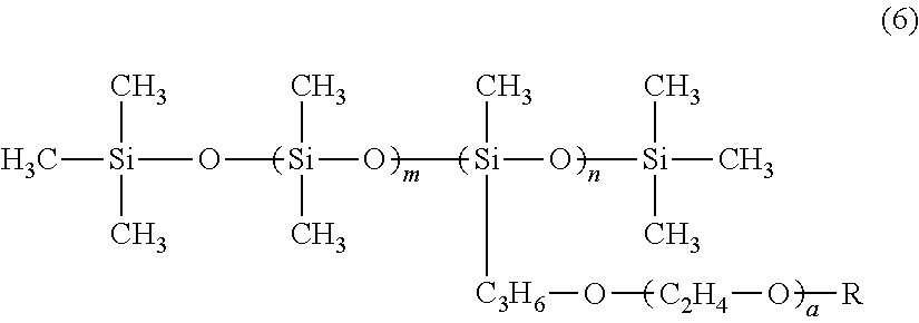
[In Formula (6), R indicates a hydrogen atom or a methyl group. a indicates an integer of 2 to 18. m indicates an integer of 0 to 50. n indicates an integer of 1 to 5.]

[R indicates a hydrocarbon chain which has 6 to 14 carbon atoms and may be branched, k: 5 to 20]

[m, n≤20, 0<m+n≤40]
R—(OCH2CH2)nH (III)
[R indicates a hydrocarbon chain which has 6 to 14 carbon atoms and may be branched, and n is 5 to 20]
[R indicates a hydrocarbon chain having 6 to 14 carbon atoms, and m and n are numbers of 20 or less]
Claims (15)
Applications Claiming Priority (3)
| Application Number | Priority Date | Filing Date | Title |
|---|---|---|---|
| JPJP2018-128843 | 2018-07-06 | ||
| JP2018128843A JP7107038B2 (en) | 2018-07-06 | 2018-07-06 | LIQUID EJECTING APPARATUS AND MAINTENANCE METHOD FOR LIQUID EJECTING APPARATUS |
| JP2018-128843 | 2018-07-06 |
Publications (2)
| Publication Number | Publication Date |
|---|---|
| US20200009871A1 US20200009871A1 (en) | 2020-01-09 |
| US11135849B2 true US11135849B2 (en) | 2021-10-05 |
Family
ID=69101825
Family Applications (1)
| Application Number | Title | Priority Date | Filing Date |
|---|---|---|---|
| US16/505,380 Active 2039-07-18 US11135849B2 (en) | 2018-07-06 | 2019-07-08 | Liquid ejecting apparatus and maintenance method of liquid ejecting apparatus |
Country Status (3)
| Country | Link |
|---|---|
| US (1) | US11135849B2 (en) |
| JP (1) | JP7107038B2 (en) |
| CN (1) | CN110682687B (en) |
Families Citing this family (6)
| Publication number | Priority date | Publication date | Assignee | Title |
|---|---|---|---|---|
| JP7298231B2 (en) * | 2019-03-26 | 2023-06-27 | コニカミノルタ株式会社 | Cleaning device, head cleaning device, and inkjet image forming device |
| JP7404897B2 (en) * | 2020-01-30 | 2023-12-26 | セイコーエプソン株式会社 | Liquid injection equipment, maintenance method for liquid injection equipment |
| JP7417191B2 (en) * | 2020-01-30 | 2024-01-18 | セイコーエプソン株式会社 | liquid injection device |
| JP2021146623A (en) * | 2020-03-19 | 2021-09-27 | 株式会社リコー | Wiping device, liquid discharge device and wiping method |
| JP2022040958A (en) * | 2020-08-31 | 2022-03-11 | コニカミノルタ株式会社 | Inkjet recording device |
| JP2022187755A (en) * | 2021-06-08 | 2022-12-20 | ブラザー工業株式会社 | Printer, control method and control program |
Citations (13)
| Publication number | Priority date | Publication date | Assignee | Title |
|---|---|---|---|---|
| JP2004338223A (en) | 2003-05-15 | 2004-12-02 | Konica Minolta Medical & Graphic Inc | Ink-jet printer |
| JP2005021809A (en) | 2003-07-02 | 2005-01-27 | Seiko Epson Corp | Droplet discharge apparatus, wiping head unit for droplet discharge head, electro-optic device and method of manufacturing electro-optic device |
| JP2005224700A (en) | 2004-02-12 | 2005-08-25 | Seiko Epson Corp | Method of wiping droplet discharge head, wiping apparatus and droplet discharge apparatus, electro-optic device, method of manufacturing electro-optic device, and electronic equipment |
| JP2007007977A (en) | 2005-06-30 | 2007-01-18 | Seiko Epson Corp | Liquid droplet discharge device and method for maintenance |
| JP2007275793A (en) | 2006-04-07 | 2007-10-25 | Seiko Epson Corp | Wiping device, droplet discharge device, manufacturing method for electro-optical device, electro-optical device and electronic equipment |
| US20100245466A1 (en) | 2009-03-31 | 2010-09-30 | Hiroshi Inoue | Head cleaning method and head cleaning apparatus |
| JP2010234666A (en) | 2009-03-31 | 2010-10-21 | Fujifilm Corp | Head cleaning method and apparatus |
| JP2010280067A (en) | 2009-06-02 | 2010-12-16 | Seiko Epson Corp | Liquid droplet ejector, and control method of wiping of ejection head |
| US20120038707A1 (en) | 2010-08-12 | 2012-02-16 | Noriaki Maida | Nozzle surface cleaning apparatus and droplet ejection apparatus |
| JP2013159008A (en) | 2012-02-03 | 2013-08-19 | Seiko Epson Corp | Printing device, and wetting liquid supply method |
| JP2013159007A (en) | 2012-02-03 | 2013-08-19 | Seiko Epson Corp | Printing device, and wiping method |
| JP2017159491A (en) | 2016-03-08 | 2017-09-14 | セイコーエプソン株式会社 | Liquid jet device |
| US20170334209A1 (en) | 2016-05-19 | 2017-11-23 | Fujifilm Corporation | Nozzle surface wiping device, liquid discharge apparatus, and head cleaning method |
Family Cites Families (7)
| Publication number | Priority date | Publication date | Assignee | Title |
|---|---|---|---|---|
| JP5356463B2 (en) * | 2011-07-21 | 2013-12-04 | 富士フイルム株式会社 | Nozzle surface cleaning device and droplet discharge device |
| JP5966541B2 (en) * | 2012-04-10 | 2016-08-10 | セイコーエプソン株式会社 | Liquid ejector |
| EP2919996A1 (en) * | 2012-11-19 | 2015-09-23 | OCE-Technologies B.V. | Assembly of a print head and a maintenance unit and method for the use of said assembly |
| JP6135197B2 (en) * | 2013-03-07 | 2017-05-31 | セイコーエプソン株式会社 | Liquid ejector |
| JP2016221777A (en) * | 2015-05-28 | 2016-12-28 | セイコーエプソン株式会社 | Liquid jet head unit, liquid jet device and wiping method |
| JP6606958B2 (en) * | 2015-10-05 | 2019-11-20 | セイコーエプソン株式会社 | Liquid ejecting apparatus and cleaning apparatus |
| JP6642129B2 (en) * | 2016-03-08 | 2020-02-05 | セイコーエプソン株式会社 | Liquid ejection device |
-
2018
- 2018-07-06 JP JP2018128843A patent/JP7107038B2/en active Active
-
2019
- 2019-07-02 CN CN201910590610.4A patent/CN110682687B/en active Active
- 2019-07-08 US US16/505,380 patent/US11135849B2/en active Active
Patent Citations (15)
| Publication number | Priority date | Publication date | Assignee | Title |
|---|---|---|---|---|
| JP2004338223A (en) | 2003-05-15 | 2004-12-02 | Konica Minolta Medical & Graphic Inc | Ink-jet printer |
| JP2005021809A (en) | 2003-07-02 | 2005-01-27 | Seiko Epson Corp | Droplet discharge apparatus, wiping head unit for droplet discharge head, electro-optic device and method of manufacturing electro-optic device |
| JP2005224700A (en) | 2004-02-12 | 2005-08-25 | Seiko Epson Corp | Method of wiping droplet discharge head, wiping apparatus and droplet discharge apparatus, electro-optic device, method of manufacturing electro-optic device, and electronic equipment |
| JP2007007977A (en) | 2005-06-30 | 2007-01-18 | Seiko Epson Corp | Liquid droplet discharge device and method for maintenance |
| JP2007275793A (en) | 2006-04-07 | 2007-10-25 | Seiko Epson Corp | Wiping device, droplet discharge device, manufacturing method for electro-optical device, electro-optical device and electronic equipment |
| US20100245466A1 (en) | 2009-03-31 | 2010-09-30 | Hiroshi Inoue | Head cleaning method and head cleaning apparatus |
| JP2010234666A (en) | 2009-03-31 | 2010-10-21 | Fujifilm Corp | Head cleaning method and apparatus |
| JP2010280067A (en) | 2009-06-02 | 2010-12-16 | Seiko Epson Corp | Liquid droplet ejector, and control method of wiping of ejection head |
| US20120038707A1 (en) | 2010-08-12 | 2012-02-16 | Noriaki Maida | Nozzle surface cleaning apparatus and droplet ejection apparatus |
| JP2012040693A (en) | 2010-08-12 | 2012-03-01 | Fujifilm Corp | Nozzle surface cleaning apparatus and droplet ejection apparatus |
| JP2013159008A (en) | 2012-02-03 | 2013-08-19 | Seiko Epson Corp | Printing device, and wetting liquid supply method |
| JP2013159007A (en) | 2012-02-03 | 2013-08-19 | Seiko Epson Corp | Printing device, and wiping method |
| JP2017159491A (en) | 2016-03-08 | 2017-09-14 | セイコーエプソン株式会社 | Liquid jet device |
| US20170334209A1 (en) | 2016-05-19 | 2017-11-23 | Fujifilm Corporation | Nozzle surface wiping device, liquid discharge apparatus, and head cleaning method |
| JP2017205954A (en) | 2016-05-19 | 2017-11-24 | 富士フイルム株式会社 | Nozzle surface wiping device, liquid discharge device and head cleaning method |
Also Published As
| Publication number | Publication date |
|---|---|
| CN110682687B (en) | 2022-09-16 |
| JP7107038B2 (en) | 2022-07-27 |
| US20200009871A1 (en) | 2020-01-09 |
| JP2020006557A (en) | 2020-01-16 |
| CN110682687A (en) | 2020-01-14 |
Similar Documents
| Publication | Publication Date | Title |
|---|---|---|
| US11135849B2 (en) | Liquid ejecting apparatus and maintenance method of liquid ejecting apparatus | |
| US9597877B2 (en) | Ink jet recording apparatus | |
| CN111332021B (en) | Liquid ejecting apparatus | |
| US9796184B2 (en) | Liquid ejecting apparatus | |
| EP3446880B1 (en) | Cap device and liquid ejecting apparatus | |
| US9925779B2 (en) | Liquid ejecting apparatus | |
| JP2016155251A (en) | Liquid jet device | |
| JP2016155252A (en) | Liquid jet device | |
| JP7087303B2 (en) | Cap device and liquid injection device | |
| JP6435913B2 (en) | Liquid ejecting apparatus and maintenance method for liquid ejecting apparatus | |
| JP6652185B2 (en) | Liquid injection device | |
| JP6981103B2 (en) | Liquid injection device and cap device | |
| JP2017159491A (en) | Liquid jet device | |
| JP7151826B2 (en) | liquid injector | |
| US11267247B2 (en) | Liquid ejecting apparatus and maintenance method for liquid ejecting apparatus | |
| JP6915707B2 (en) | Liquid injection device |
Legal Events
| Date | Code | Title | Description |
|---|---|---|---|
| AS | Assignment |
Owner name: SEIKO EPSON CORPORATION, JAPAN Free format text: ASSIGNMENT OF ASSIGNORS INTEREST;ASSIGNORS:MATSUOKA, HIROKI;NAKAMURA, CHIKASHI;KURAMATA, SHUNSUKE;AND OTHERS;SIGNING DATES FROM 20190410 TO 20190517;REEL/FRAME:049692/0011 |
|
| FEPP | Fee payment procedure |
Free format text: ENTITY STATUS SET TO UNDISCOUNTED (ORIGINAL EVENT CODE: BIG.); ENTITY STATUS OF PATENT OWNER: LARGE ENTITY |
|
| STPP | Information on status: patent application and granting procedure in general |
Free format text: DOCKETED NEW CASE - READY FOR EXAMINATION |
|
| STPP | Information on status: patent application and granting procedure in general |
Free format text: RESPONSE TO NON-FINAL OFFICE ACTION ENTERED AND FORWARDED TO EXAMINER |
|
| STPP | Information on status: patent application and granting procedure in general |
Free format text: NON FINAL ACTION MAILED |
|
| STPP | Information on status: patent application and granting procedure in general |
Free format text: RESPONSE TO NON-FINAL OFFICE ACTION ENTERED AND FORWARDED TO EXAMINER |
|
| STPP | Information on status: patent application and granting procedure in general |
Free format text: NOTICE OF ALLOWANCE MAILED -- APPLICATION RECEIVED IN OFFICE OF PUBLICATIONS |
|
| STPP | Information on status: patent application and granting procedure in general |
Free format text: PUBLICATIONS -- ISSUE FEE PAYMENT VERIFIED |
|
| STCF | Information on status: patent grant |
Free format text: PATENTED CASE |