US11125991B2 - Optical scanning device - Google Patents
Optical scanning device Download PDFInfo
- Publication number
- US11125991B2 US11125991B2 US16/668,355 US201916668355A US11125991B2 US 11125991 B2 US11125991 B2 US 11125991B2 US 201916668355 A US201916668355 A US 201916668355A US 11125991 B2 US11125991 B2 US 11125991B2
- Authority
- US
- United States
- Prior art keywords
- polygon mirror
- restricting member
- rotor
- linear expansion
- expansion coefficient
- Prior art date
- Legal status (The legal status is an assumption and is not a legal conclusion. Google has not performed a legal analysis and makes no representation as to the accuracy of the status listed.)
- Expired - Fee Related, expires
Links
Images


Classifications
-
- G—PHYSICS
- G02—OPTICS
- G02B—OPTICAL ELEMENTS, SYSTEMS OR APPARATUS
- G02B26/00—Optical devices or arrangements for the control of light using movable or deformable optical elements
- G02B26/08—Optical devices or arrangements for the control of light using movable or deformable optical elements for controlling the direction of light
- G02B26/10—Scanning systems
- G02B26/12—Scanning systems using multifaceted mirrors
- G02B26/121—Mechanical drive devices for polygonal mirrors
-
- G—PHYSICS
- G03—PHOTOGRAPHY; CINEMATOGRAPHY; ANALOGOUS TECHNIQUES USING WAVES OTHER THAN OPTICAL WAVES; ELECTROGRAPHY; HOLOGRAPHY
- G03G—ELECTROGRAPHY; ELECTROPHOTOGRAPHY; MAGNETOGRAPHY
- G03G15/00—Apparatus for electrographic processes using a charge pattern
- G03G15/04—Apparatus for electrographic processes using a charge pattern for exposing, i.e. imagewise exposure by optically projecting the original image on a photoconductive recording material
- G03G15/04036—Details of illuminating systems, e.g. lamps, reflectors
-
- G—PHYSICS
- G03—PHOTOGRAPHY; CINEMATOGRAPHY; ANALOGOUS TECHNIQUES USING WAVES OTHER THAN OPTICAL WAVES; ELECTROGRAPHY; HOLOGRAPHY
- G03G—ELECTROGRAPHY; ELECTROPHOTOGRAPHY; MAGNETOGRAPHY
- G03G15/00—Apparatus for electrographic processes using a charge pattern
- G03G15/04—Apparatus for electrographic processes using a charge pattern for exposing, i.e. imagewise exposure by optically projecting the original image on a photoconductive recording material
- G03G15/0409—Details of projection optics
-
- G—PHYSICS
- G03—PHOTOGRAPHY; CINEMATOGRAPHY; ANALOGOUS TECHNIQUES USING WAVES OTHER THAN OPTICAL WAVES; ELECTROGRAPHY; HOLOGRAPHY
- G03G—ELECTROGRAPHY; ELECTROPHOTOGRAPHY; MAGNETOGRAPHY
- G03G15/00—Apparatus for electrographic processes using a charge pattern
- G03G15/04—Apparatus for electrographic processes using a charge pattern for exposing, i.e. imagewise exposure by optically projecting the original image on a photoconductive recording material
- G03G15/043—Apparatus for electrographic processes using a charge pattern for exposing, i.e. imagewise exposure by optically projecting the original image on a photoconductive recording material with means for controlling illumination or exposure
Definitions
- the present invention relates to an optical scanning device provided in an image forming apparatus.
- an optical scanning device is used forming an electrostatic latent image on a photosensitive drum, which scans a photosensitive drum via a scanning lens with a laser beam which has been light-modulated in accordance with an image signal and has been deflected by a polygon mirror.
- Japanese Patent Laid-Open Application No. 2015-225199 describes an optical scanning device including a polygon mirror, a rotor that supports the polygon mirror and a motor having a spring that presses the polygon mirror against the rotor.
- the polygon mirror has a through-hole and a restricting member is disposed in the through-hole such that the restricting member is in contact with a rotor and a spring to restrict the spring from moving toward the rotor.
- the present invention is made to solve the above-described problem, and an object of the present invention is to provide an optical scanning device that suppresses a change in position of the polygon mirror or distortion of the reflecting surface of the polygon mirror due to a temperature change.
- a representative configuration of an optical scanning device includes: a motor including a rotor capable of rotating integrally with a rotating shaft; a polygon mirror including a through-hole; a spring configured to be engaged to the rotating shaft that is inserted into the through-hole and configured to press the polygon mirror onto the rotor; and a restricting member disposed in the through-hole of the polygon mirror, the restricting member being configured to be in contact with the rotor and the spring and to restrict the spring from moving toward a side of the rotor, wherein a linear expansion coefficient of the restricting member is less than a linear expansion coefficient of the polygon mirror.
- FIG. 1 is a cross-sectional view showing a configuration of an image forming apparatus.
- FIG. 2 is a perspective view showing a configuration of an optical scanning device.
- FIG. 3 is a cross-sectional view showing a configuration of a polygon motor unit of the first embodiment.
- FIG. 4 is a plan view showing the configuration of the polygon motor unit of the first embodiment.
- FIG. 5 is a cross-sectional view showing a configuration of a polygon motor unit of the first embodiment.
- FIG. 6 is a plan view showing a modification example of a configuration of a polygon motor unit of the first embodiment.
- FIG. 7A is a side view of the polygon mirror in a state where the polygon mirror is not affected by thermal expansion.
- FIG. 7B is a plan view of the polygon mirror in a state where the polygon mirror is not affected by thermal expansion.
- FIG. 8A is a side view of the polygon mirror in a state where the polygon mirror is affected by thermal expansion.
- FIG. 8B is a plan view of the polygon mirror in a state where the polygon mirror is affected by thermal expansion.
- FIG. 9 is a cross-sectional view illustrating a configuration of the polygon motor unit of the second embodiment.
- FIG. 10 is a view for explaining the selection range of the linear expansion coefficient of the restricting member and the linear expansion coefficient of the polygon mirror according to the second embodiment.
- FIG. 11A is a view showing an optical path of a laser beam in a state where the reflecting surface of the polygon mirror is not deformed.
- FIG. 11B is a view showing an optical path of the laser beam in a state where the reflecting surface of the polygon mirror is deformed.
- FIG. 12 is a view for explaining a problem in a polygon motor unit as a comparative example.
- FIG. 1 is a cross-sectional view showing the configuration of the image forming apparatus 100 .
- the image forming apparatus 100 shown in FIG. 1 forms a multicolor image using a plurality of colors of toner (developer).
- the image forming apparatus 100 can be applied to an image forming apparatus for a single color image.
- the image forming apparatus 100 may be, for example, any of a printing apparatus, a printer, a copying machine, a multifunctional printer (IMEP) and a facsimile apparatus.
- the suffixes Y, M, C, and K of the reference numerals indicate that the colors of the toners used by the corresponding members are yellow Y, magenta M, cyan C and black K, respectively. In the following description, the suffixes Y, M, C and K may be omitted when it is not necessary to distinguish the colors.
- the image forming apparatus 100 includes four image forming stations as image forming portions that form toner images using toners as developers of yellow Y, magenta M, cyan C and black K, respectively.
- the image forming units corresponding to the colors include the photosensitive drums 102 Y, 102 M, 102 C and 102 K as image bearing members, respectively.
- the charging portions 103 Y, 103 M, 103 C and 103 K as charging devices, the optical scanning devices 104 Y, 104 M, 104 C and 104 K, and the developing units 105 Y, 105 M, 105 C and 105 K as developing devices are disposed, respectively.
- cleaning portions (not shown) are further arranged respectively as cleaning devices.
- the intermediate transfer belt 107 made of an endless belt as an intermediate transfer member is arranged below the photosensitive drums 102 Y, 102 M, 102 C and 102 K.
- the intermediate transfer belt 107 is stretched around the driving roller 108 and the driven rollers 109 and 110 .
- the outer circumferential surface of the intermediate transfer belt 107 moves in the clockwise direction in FIG. 1 as the driving roller 108 rotates.
- the primary transfer bias blades 111 Y, 111 M, 111 C and 111 K as primary transfer devices are respectively disposed.
- the image forming apparatus 100 includes the secondary transfer bias roller 112 as a secondary transfer device for transferring a toner image formed on the outer circumferential surface of the intermediate transfer belt 107 onto the recording material 1 such as a sheet of paper.
- the image forming apparatus 100 further includes the fixing unit 113 as a fixing device for fixing the toner image transferred onto the recording material 1 to the recording material 1 .
- the image forming operation performed in the image forming portion corresponding to each color is the same as those of the other colors. Therefore, hereinafter, the image forming operation in the image forming portion corresponding to the color yellow Y will be described as an example and a duplicate description is omitted for the image forming in the image forming portions corresponding to the colors magenta M, cyan C and black K.
- the charging portion 103 Y of the image forming portion corresponding to the color yellow Y uniformly charges the surface of the photosensitive drum 102 Y that is driven to rotate in the counterclockwise direction in FIG. 1 .
- the optical scanning device 104 Y emits a plurality of laser beams L and scans the uniformly charged surface of the photosensitive drum 102 Y with the plurality of laser beams L to expose the surface of the photosensitive drum 102 Y.
- the electrostatic latent image 210 shown in FIG. 2 is formed on the surface of the photosensitive drum 102 Y that rotates in the counterclockwise direction in FIG. 1 .
- the electrostatic latent image 210 formed on the surface of the photosensitive drum 102 Y is developed as a toner image of color yellow Y by the developing portion 105 Y.
- a toner image of the color yellow Y is formed on the surface of the photosensitive drum 102 Y.
- toner images of the color magenta M, the color cyan C and the color black K are respectively formed on the photosensitive drums 102 M, 102 C and 102 K in the same process as the image forming portion corresponding to the color yellow Y.
- the primary transfer bias blades 111 Y, 111 M, 111 C and 111 K respectively apply a transfer bias to the intermediate transfer belt 107 .
- toner images of four colors of yellow Y, magenta M, cyan C, and black K respectively formed on the surface of the photosensitive drums 102 are primarily transferred and superimposed on the outer circumferential surface of the intermediate transfer belt 107 .
- a toner image with four toner colors formed and superimposed on the outer circumferential surface of the intermediate transfer belt 107 is transferred to the secondary transfer nip portion 14 between the secondary transfer bias roller 112 and the outer circumferential surface of the intermediate transfer belt 107 as the outer circumferential surface of the intermediate transfer belt 107 moves.
- the recording materials 1 accommodated in the feeding cassette 115 are fed out by the feeding roller 2 , and separated and fed one by one in cooperation with a separation mechanism (not shown). Thereafter, the leading end of the recording material 1 conveyed by the conveying rollers 3 to 5 abuts against the nip portion of the registration roller 6 that has been stopped so that the skew of the recording material 1 is corrected.
- the recording material 1 is conveyed to the secondary transfer nip portion 14 by the registration roller 6 in accordance with the timing at which the toner image formed on the outer circumferential surface of the intermediate transfer belt 107 is conveyed to the secondary transfer nip portion 14 .
- a secondary transfer bias is applied to the secondary transfer bias roller 112 from a secondary transfer power source (not shown) so that the toner image born on the outer circumferential surface of the intermediate transfer belt 107 in the secondary transfer nip portion 14 is secondarily transferred onto the recording material 1 . Residual toner remaining on the outer circumferential surface of the intermediate transfer belt 107 after the secondary transfer is removed by the cleaner 7 as a cleaning device.
- the toner image formed on the recording material 1 is fixed to the recording material 1 by being heated and pressed while being nipped and conveyed by a heating roller and a pressing roller provided at the fixing portion 113 .
- the recording material 1 to which the toner image is fixed is discharged to the discharge portion 116 .
- the recording material 1 that has passed through the fixing unit 113 is guided to the reversing path 8 where the recording material 1 is reversed, and thereafter the recording material 1 is placed on the double-side path 10 by the reversing roller 9 .
- the recording material 1 conveyed by the conveying rollers 11 and 12 provided at the double-side path 10 joins the conveying path 13 and printing is performed on the second side in the same manner as the printing on the first side described above. Thereafter, the recording material 1 is discharged to the discharge portion 116 .
- FIG. 2 is a perspective view showing the configuration of the optical scanning device 104 .
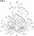
- FIG. 3 is a cross-sectional view showing the configuration of the polygon motor unit 300 of the present embodiment.
- the optical scanning device 104 shown in FIG. 2 includes the light source 201 , the collimator lens 202 , the polygon motor unit 300 , the polygon mirror 308 as a rotary polygon mirror, the motor 301 and the f ⁇ lens 205 as a scanning lens.
- the f ⁇ lens 205 has a lens characteristic (f ⁇ characteristic) that when the laser beam L enters at the angle ⁇ , an image having a size (f ⁇ ) obtained by multiplying the angle ⁇ by the focal length f of the f ⁇ lens 205 is formed.
- the optical scanning device 104 further includes a BD (Beam Detect) sensor 206 that detects the laser beam L, and the like.
- the polygon motor unit 300 includes the polygon mirror 308 and the motor 301 .
- the motor 301 has the rotor 302 that can rotate integrally with the shaft 305 as a rotating shaft.
- the motor 301 drives the polygon mirror 308 to rotate.
- the polygon mirror 308 is a rotating polygon mirror and has a plurality of reflecting surfaces 308 a to 308 d that are mirror surfaces as deflection surfaces along the axial direction of the shaft 305 shown in FIG. 3 (vertical direction in FIG. 3 ).
- the circular through-hole 308 g is provided at the center of the polygon mirror 308 .
- the polygon mirror 308 is formed as a hexahedron composed of the upper reflecting surface 308 e , the lower reflecting surface 308 f , and the reflecting surfaces 308 a to 308 d as four side surfaces.
- the upper reflecting surface 308 e and the lower reflecting surface 308 f are square and the reflecting surfaces 308 a to 308 d are rectangular.
- One reflecting surface or reflecting surfaces other than four may be provided instead of the four reflecting surfaces 308 a to 308 d.
- the laser beam L emitted from the light source 201 is deflected according to the rotation of the polygon mirror 308 that rotates in the clockwise direction in FIG. 2 around the shaft 305 as a rotational center.
- the light source 201 emits the laser beam L to expose the surface of the photosensitive drum 102 .
- the polygon mirror 308 is an example of a rotating polygon mirror that deflects the laser beam L on any one of the plurality of reflecting surfaces 308 a to 308 d while rotating so that the laser beam L scans the surface of the photosensitive drum 102 .
- the light source 201 is driven by a driving current supplied from a laser driver (not shown).
- the light source 201 emits light when supplied with a driving current from a laser driver (not shown), and emits the laser beam L having a light amount corresponding to the driving current.
- the light source 201 generally includes n (n is a natural number) laser diodes LD as light-emitting elements (light-emitting points).
- n is an integer of 2 or more, and a multi-beam method is used in which the surface of the photosensitive drum 102 is scanned with a plurality of laser beams L emitted from a plurality of laser diodes LD.
- the collimator lens 202 changes the laser beam L emitted from the light source 201 into parallel light.
- the laser beam L that has passed through the collimator lens 202 is incident on any one of the reflecting surfaces 308 a to 308 d included in the polygon mirror 308 and is reflected by the incident reflecting surface.
- the polygon mirror 308 is driven by the motor 301 so as to rotate in the clockwise direction in FIG. 2 .
- the polygon mirror 308 is driven to rotate at a constant speed (constant angular speed) while the laser beam L scans the surface of the photosensitive drum 102 in order to form the electrostatic latent image 210 on the surface of the uniformly charged photosensitive drum 102 .
- the polygon mirror 308 reflects the laser beam L on each of the reflecting surfaces 308 a to 308 d while rotating so that the incident laser beam L is deflected at continuous angles.
- the laser beam L deflected by the polygon mirror 308 is incident on the f ⁇ lens 205 .
- the laser beam L passes through the f ⁇ lens 205 to form a beam spot on the surface of the photosensitive drum 102 and scans the photosensitive drum 102 at a constant speed in the main scanning direction.
- an electrostatic latent image 210 is formed on the surface of the photosensitive drum 102 .
- the main scanning direction is a direction parallel to the surface of the photosensitive drum 102 and orthogonal to the moving direction of the surface of the photosensitive drum 102 .
- the sub-scanning direction is the moving direction of the surface of the photosensitive drum 102 (the direction orthogonal to the main scanning direction).
- the BD sensor 206 is disposed at a position on the scanning start side of the laser beam L in the scanning path of the laser beam L that has passed through the f ⁇ lens 205 .
- the BD sensor 206 is used as an optical sensor for detecting the laser beam L.
- the BD sensor 206 When the laser beam L is incident on the BD sensor 206 for each scanning period of the laser beam L, the BD sensor 206 generates and outputs a BD signal as a detection signal indicating that the laser beam L has been detected.
- the BD signal output from the BD sensor 206 is used as a synchronization signal serving as a reference for image writing timing in the main scanning direction.
- the light source 201 is controlled to forcibly emit the laser beam L during a certain period for the laser beam L to be incident on the BD sensor 206 in order to output a BD signal from the BD sensor 206 for each scanning period of the laser beam L.
- the polygon motor unit 300 shown in FIG. 3 includes the motor 301 , the polygon mirror 308 , the holding spring 309 , and the restricting member 310 .
- the holding spring 309 is provided with the cylindrical portion 309 a that is engaged to the shaft 305 serving as a rotational shaft inserted into the through-hole 308 g of the polygon mirror 308 .
- the upper-end portion 309 a 1 of the cylindrical portion 309 a of the holding spring 309 abuts against the bottom surface 305 a 1 of the head portion 305 a of the shaft 305 .
- the pressing portion 309 d presses the pressed portion 308 e 1 onto the upper surface 308 e of the polygon mirror 308 by the elastic force of the holding spring 309 , and presses the abutting portion 308 f 1 on the lower surface 308 f of the polygon mirror 308 onto the abutted portion 302 a on the upper surface of the rotor 302 .
- the motor 301 includes the rotor 302 , the rotary magnet 303 , the shaft 305 , the bearing 306 , the excitation coil 304 and the circuit board 307 .
- the rotor 302 is integrally provided with the rotary magnet 303 and the shaft 305 .
- the rotary magnet 303 has S poles and N poles that are alternately magnetized and is fixed to the inner circumferential surface of the rotor 302 .
- the shaft 305 is rotatably supported by the bearing 306 .
- the bearing 306 may be realized by a ball bearing as a rolling bearing, a metal bearing as a sliding bearing, a dynamic pressure bearing as a fluid bearing or the like.
- a plurality of energizing coils 304 are provided at positions facing the rotary magnet 303 on the circuit board 307 .
- the bearing 306 and the energizing coils 304 are supported on the circuit board 307 .
- a ring-shaped restricting member 310 is placed in the circular through-hole 308 g provided at the center of the polygon mirror 308 .
- the restricting member 310 comes into contact with the abutted portion 302 b on the upper surface of the rotor 302 and the pressing portion 309 b of the holding spring 309 and restricts the movement of the holding spring 309 toward the rotor 302 (rotor side).
- the shaft 305 is slidably inserted into the circular through-hole 310 c provided at the central portion of the restricting member 310 .
- the cylindrical portion 309 a is provided at the center of the holding spring 309 and the shaft 305 is slidably inserted into the cylindrical portion 309 a .
- the ring-shaped pressing portion 309 b shown in FIG. 4 is provided continuously to the cylindrical portion 309 a .
- the pressing portion 309 b presses the restricting member 310 toward the rotor 302 by the elastic force of the holding spring 309 .
- the eight arm portions 309 c are provided in the radial directions continuously to the ring-shaped pressing portion 309 b .
- the square-shaped pressing portions 309 d are provided continuously to the arm portions 309 c , respectively.
- the pressing portions 309 d press the polygon mirror 308 toward the rotor 302 by the elastic force of the holding spring 309 .
- the restricting member 310 restricts the holding spring 309 from moving toward the rotor 302 .
- the elastic cylindrical portion 309 a is elastically deformed and expands to open so that the elastic cylindrical portion 309 a passes through the head portion 305 a and is engaged to the shaft 305 .
- the cylindrical portion 309 a engaged to the shaft 305 is elastically deformed and contracts so that the upper-end portion 309 a 1 of the cylindrical portion 309 a abuts against the bottom surface 305 a 1 of the head portion 305 a of the shaft 305 .
- the holding spring 309 is restricted from moving toward the opposite side of the rotor 302 .
- FIG. 4 is a plan view showing the configuration of the polygon motor unit 300 of the present embodiment.
- the holding spring 309 has arm portions 309 c .
- the arm portions 309 c respectively connect the ring-shaped pressing portion 309 b that abuts against the upper surface 310 a of the restricting member 310 and the square-shaped pressing portions 309 d that abut against the pressed portion 308 e 1 of the upper surface 308 e of the polygon mirror 308 .
- the width of the arm portions 309 c is less than the width of the pressing portions 309 d.
- the holding spring 309 is assembled to the polygon motor unit 300 .
- the holding spring 309 is elastically deformed around the arm portions 309 c .
- the pressing portion 309 d of the holding spring 309 presses the pressed portion 308 e 1 of the upper surface 308 e of the polygon mirror 308 by the stress when the arm portions 309 c are elastically deformed.
- the polygon mirror 308 is pressed against the rotor 302 .
- the motor 301 is driven to rotate, the rotor 302 , the polygon mirror 308 , the restricting member 310 , the holding spring 309 and the shaft 305 rotate integrally around the shaft 305 as a rotation center.
- FIGS. 11A and 11B the influence on the optical path by the reflection position of the laser beam L incident on the reflecting surface 308 a of the polygon mirror 308 will be described with reference to FIGS. 11A and 11B .
- FIGS. 11A and 11B only the polygon mirror 308 and the shaft 305 that serves as the rotation center of the polygon mirror 308 are simply shown to schematically illustrate the optical path.
- FIG. 11A shows the state where the laser beam L is incident and reflected at the desired position with the desired angle on the reflecting surface 308 a of the polygon mirror 308 arranged parallel to the axial direction of the shaft 305 that is the rotation center of the polygon mirror 308 .
- the laser beam L With the laser beam L reflected by the reflecting surface 308 a , the laser beam L passes through the optical path indicated by FIG. 11A so that the laser beam L is correctly incident on the photosensitive drum (not shown) in the sub-scanning direction of the photosensitive drum. As a result, an image is formed without density unevenness.
- FIG. 11B shows the state where the reflecting surface 308 a of the polygon mirror 308 is inclined at a predetermined angle with respect to the axial direction of the shaft 305 that is the rotation center of the polygon mirror 308 . Due to the fact that the reflecting surface 308 a of the polygon mirror 308 is inclined with respect to the axial direction of the shaft 305 , the incident angle and the incident position of the laser beam L with respect to the reflecting surface 308 a of the polygon mirror 308 change.
- the polygon mirror 308 has a plurality of reflecting surfaces and the inclination angles of the reflecting surfaces with respect to the axis direction of the shaft 305 respectively have different variations. For this reason, when the sub-scanning is performed, the density in the positions of the laser beam L incident on the photosensitive drum varies so that density unevenness occurs in the sub-scanning direction.
- FIG. 11B shows that the reflecting surfaces of the polygon mirror 308 have different inclination angles with respect to the axial direction of the shaft 305 .
- the positions of the reflecting surfaces change due to the displacement of the polygon mirror 308 .
- the positions of the laser beam incident on reflecting surfaces of the polygon mirror 308 respectively vary in the sub-scanning direction of the photosensitive drum. As a result, density unevenness occurs in the sub-scanning direction.
- the polygon mirror 308 and the restricting member 310 that are pressed against the rotor 302 by the holding spring 309 are thermally deformed in accordance with their inherent linear expansion coefficients.
- the length and volume of the material expand with increasing temperature.
- the linear expansion coefficient represents the ratio of the increase in the length of material to the original length when the temperature rises by 1° C.
- FIG. 12 is a cross-sectional view showing the configuration of the polygon motor unit 300 for explaining the problem of the comparative example.
- the restricting member 310 shown in FIG. 12 is made from paper Bakelite and its linear expansion coefficient A 0 is 160 ( ⁇ 10 ⁇ 6 /° C.).
- the material of the polygon mirror 308 is polycarbonate (PC), and its linear expansion coefficient B 0 is 65 ( ⁇ 10 ⁇ 6 /° C.).
- the motor 301 is stopped at the environmental temperature of 25° C., which is normal temperature, at the place where the polygon motor unit 300 is placed.
- the normal temperature is a normal environmental temperature in a factory where the assembly operation of the polygon motor unit 300 is performed and means about 25° C. ⁇ 5° C.
- the thickness U 0 of the polygon mirror 308 is 10 mm.
- the pressed portion 308 e 1 of the polygon mirror 308 that is pressed by the holding spring 309 is considered.
- the abutting portion 308 f 1 provided on the lower surface 308 f of the polygon mirror 308 that is in contact with the upper surface of the rotor 302 is considered.
- the thickness U 0 from the pressed portion 308 e 1 to the abutting portion 308 f 1 of the polygon mirror 308 in the axial direction of the shaft 305 (the vertical direction in FIG. 12 ) is the thickness of the polygon mirror 308 .
- the thickness X 0 of the restricting member 310 from the pressed portion 310 a 1 of the restricting member 310 that is pressed by the holding spring 309 to the lower surface 310 b of the restricting member 310 that is in contact with the upper surface of the rotor 302 in the axial direction of the shaft 305 (vertical direction in FIG. 12 ) is 8 mm.
- the heat is generated from the parts of the motor 301 when the motor 301 rotates about the shaft 305 as a rotation center.
- the heat is generated through a copper loss and an iron loss occurring when an electric current starts to flow through the exciting coil 304 attached to the circuit board 307 .
- the shaft 305 is rotatably supported by the bearing 306 provided on the circuit board 307 and the heat is also generated due to friction between the rotating shaft 305 and the bearing 306 . This heat is transmitted to the polygon mirror 308 and the restricting member 310 via the rotor 302 .
- the influence when the rotation of the motor 301 continues and the temperature of the polygon mirror 308 and the restricting member 310 exceeds the normal temperature and reaches 80° C. is considered.
- the case is considered where the assembly process of the polygon motor unit 300 is performed at 25° C. as normal temperature and the temperature of the motor rises from 25° C. as normal temperature to 80° C. due to the heat generated by the rotation of the motor 301 .
- the parts of the polygon motor unit 300 thermally expand under the influence of the temperature change ⁇ T calculated by the following Equation 1.
- the thickness U 1 of the polygon mirror 308 that changes due to the temperature change ⁇ T in Equation 1 is calculated by the following Equation 2.
- the pressed portion 308 e 1 of the polygon mirror 308 pressed by the holding spring 309 is considered for the thickness U 1 of the polygon mirror 308 .
- the abutting portion 308 f 1 provided on the lower surface 308 f of the polygon mirror 308 that is in contact with the abutting portion 302 a on the upper surface of the rotor 302 is considered.
- the thickness U 1 of the polygon mirror 308 is from the pressed portion 308 e 1 to the abutting portion 308 f 1 in the axial direction of the shaft 305 (vertical direction in FIG. 12 ).
- the linear expansion coefficient B 0 of polycarbonate (PC) which is the material of the polygon mirror 308 is set to 65 ( ⁇ 10 6 /° C.).
- the thickness X 1 of the restricting member 310 from the pressed portion 310 a 1 of the restricting member 310 pressed by the holding spring 309 to the lower surface 310 b that is in contact with the abutted portion 302 b on the upper surface of the rotor 302 under influence of the temperature change ⁇ T in the Equation 1 is calculated by the following Equation 3.
- the thickness X 0 of the restricting member 310 at 25° C. as normal temperature is 8 mm
- the linear expansion coefficient A 0 of the paper bakelite that is the material of the restricting member 310 is set to 160 ( ⁇ 10 6 /° C.).
- the polygon mirror 308 thermally expands by 35.75 ⁇ m in the axial direction of the shaft 305 (the vertical direction in FIG. 12 ), and the restricting member 310 thermally expands by 70.4 ⁇ m in the axial direction of the shaft 305 (the vertical direction in FIG. 12 ).
- the dotted line in FIG. 12 indicates the holding spring 309 at 25° C. as normal temperature.
- the solid line in FIG. 12 indicates the holding spring 309 under the influence of thermal expansion caused by the temperature increase of the motor 301 to 80° C. due to the heat generation of the motor 301 when the motor 301 rotates.
- the cylindrical portion 309 a of the holding spring 309 is engaged so as to be movable along the outer circumference of the shaft 305 , and the upper-end portion 309 a 1 of the cylindrical portion 309 a of the holding spring 309 abuts against the bottom surface 305 a 1 of the head portion 305 a of the shaft 305 so that the upward movement of the holding spring 309 is restricted.
- the outer diameter of the bottom surface 305 a 1 of the head portion 305 a is set larger than the outer diameter of the shaft 305 .
- the holding spring 309 is provided with arm portions 309 c .
- These arm portions 309 c are elastically deformed.
- the arm portions 309 c respectively connect the ring-shaped pressing portion 309 b that presses the pressed portion 310 a 1 of the restricting member 310 with the square-shaped pressing portions 309 d that press the pressed portion 308 e 1 of the polygon mirror 308 .
- the width of the arm portions 309 c is less than the width of the pressing portions 309 d.
- the holding spring 309 presses the polygon mirror 308 against the rotor 302 at the pressing portions 309 d so that the polygon mirror 308 is fixed by the deformation stress of the arm portions 309 c .
- Equation 2 when the temperature of the polygon mirror 308 rises from 25° C. as normal temperature to 80° C., the polygon mirror 308 thermally expands, so that the thickness of the polygon mirror 308 increases by 35.75 ⁇ m. Further, when the temperature of the restricting member 310 rises from 25° C. as normal temperature to 80° C., the restricting member 310 thermally expands, so that the thickness of the restricting member 310 increases by 70.4 ⁇ m.
- the pressing portion 309 b of the holding spring 309 is pressed upwardly in FIG. 12 by 70.4 ⁇ m along the axial direction of the shaft 305 due to thermal expansion of the restricting member 310 .
- the pressing portion 309 d of the holding spring 309 is pressed upwardly in FIG. 12 by 35.75 ⁇ m along the axial direction of the shaft 305 due to thermal expansion of the polygon mirror 308 .
- the holding spring 309 at 25° C. as normal temperature as shown in the dotted line in FIG. 12 is deformed as shown in the solid line in FIG. 12 when the temperature rises from 25° C. to 80° C. due to the thermal expansion of the polygon mirror 308 and the restricting member 310 .
- the deformation of the pressing portion 309 b of the holding spring 309 that presses the pressed portion 310 a 1 of the restricting member 310 is such that the radius of curvature R of the pressing portion 309 b indicated by the dotted line in FIG. 12 is less than the radius of curvature R of the pressing portion 309 b indicated by the solid line in FIG. 12 . Therefore, the pressing force of the pressing portion 309 d of the holding spring 309 for pressing the pressed portion 308 e 1 of the polygon mirror 308 as shown by the solid line in FIG. 12 is less than that indicated by the dotted line in FIG. 12 . As a result, the polygon mirror 308 is displaced in the axial direction of the shaft 305 with respect to the rotor 302 due to the temperature change ⁇ T of the motor 301 .
- the restricting member 310 is provided in order to manage the pressing force of the holding spring 309 that presses the polygon mirror 308 . For this reason, when the material of the restricting member 310 with an inappropriate linear expansion coefficient A is selected, the function of the restricting member 310 for managing the pressing force of the holding spring 309 that presses the polygon mirror 308 is impaired. As a result, the polygon mirror 308 may be displaced in the axial direction of the shaft 305 , causing density unevenness in the sub-scanning direction.
- the linear expansion coefficient A 1 of the restricting member 310 is set to half or less than the linear expansion coefficient B 1 of the polygon mirror 308 . That is, the linear expansion coefficient A 1 of the restricting member 310 is less than the linear expansion coefficient B 1 of the polygon mirror 308 .
- the restricting member 310 can be selected so that the position of the polygon mirror 308 pressed against the rotor 302 by the holding spring 309 is not shifted.
- the materials of the polygon mirror 308 and the restricting member 310 are selected in such a range that the linear expansion coefficient B 1 of the polygon mirror 308 and the linear expansion coefficient A 1 of the restricting member 310 are in the relationship represented by the following Equation 4.
- Equation 4 A 1 ⁇ 0.5 ⁇ B 1 [Equation 4]
- FIG. 5 is a cross-sectional view showing the configuration of the polygon motor unit 300 of this embodiment.
- the material of the polygon mirror 308 shown in FIG. 5 is polycarbonate (PC), and its linear expansion coefficient B 1 is 65 ( ⁇ 10 ⁇ 6 /° C.).
- the material of the restricting member 310 is poly ether ether ketone (PEEK), and its linear expansion coefficient A 1 is 26 ( ⁇ 10 ⁇ 6 /° C.).
- the thickness U 0 of the polygon mirror 308 is considered in the environmental temperature of 25° C. as normal temperature with the motor 301 stopped.
- the pressed portion 308 e 1 provided on the upper surface 308 e of the polygon mirror 308 pressed by the pressing portion 309 d of the holding spring 309 is considered.
- the abutting portion 308 f 1 provided on the lower surface 308 f that abuts against the abutted portion 302 a on the upper surface of the rotor 302 is considered.
- the thickness U 0 in the axial direction (vertical direction in FIG. 5 ) of the shaft 305 from the pressed portion 308 e 1 to the abutting portion 308 f 1 of the polygon mirror 308 is 10 mm.
- the thickness X 0 of the restricting member 310 is considered in the environmental temperature of 25° C. as normal temperature in the state where the motor 301 is stopped. At this time, the pressed portion 310 a 1 provided on the upper surface 310 a of the restricting member 310 pressed by the pressing portion 309 b of the holding spring 309 is considered. Furthermore, the pressing portion 310 b 1 provided on the lower surface 310 b of the restricting member 310 that abuts against the abutted portion 302 b provided on the upper surface of the rotor 302 is considered.
- the thickness X 0 of the restricting member 310 in the axial direction (vertical direction in FIG. 5 ) of the shaft 305 from the pressed portion 310 a 1 to the pressing portion 310 b 1 of the restricting member 310 is 8 mm.
- the heat is generated from the parts of the motor 301 when the motor 301 rotates.
- the heat is generated from the exciting coil 304 due to copper loss and iron loss caused by an electric current flow.
- the heat is generated from the bearing 306 due to the friction between the bearing 306 and the shaft 305 . This heat is transmitted to the polygon mirror 308 and the restricting member 310 through the rotor 302 . In such a configuration, the influence when the rotation of the motor 301 continues and the temperature of the polygon mirror 308 and the restricting member 310 reaches 80° C. will be considered.
- the temperature change ⁇ T occurs from 25° C. as normal temperature in the assembly process of the polygon motor unit 300 to 80° C. due to the heat generated by the motor 301 . Therefore, the polygon mirror 308 and the restricting member 310 thermally expands due to the temperature change ⁇ T calculated by the following Equation 5.
- the thickness U 2 of the polygon mirror 308 that changes due to the temperature change ⁇ T expressed by the above Equation 5 is considered.
- the pressed portion 308 e 1 of the upper surface 308 e of the polygon mirror 308 that is pressed by the pressing portion 309 d of the holding spring 309 is considered.
- the abutting portion 308 f 1 of the lower surface 308 f of the polygon mirror 308 that abuts against the abutted portion 302 a of the rotor 302 is considered.
- the thickness U 2 of the polygon mirror 308 is from the pressed portion 308 e 1 to the abutting portion 308 f 1 in the axial direction (vertical direction in FIG. 5 ) of the shaft 305 .
- the thickness U 2 of the polygon mirror 308 that changes with the temperature change ⁇ T shown in the above Equation 5 is considered.
- the thickness U 0 of the polygon mirror 308 in the environmental temperature of 25° C. as normal temperature is 10 mm.
- the linear expansion coefficient B 1 of the polygon mirror 308 made of polycarbonate (PC) is 65 ( ⁇ 10 ⁇ 6 /° C.). Using these factors, the thickness U 2 of the polygon mirror 308 is calculated by the following Equation 6.
- the thickness X 0 of the restricting member 310 in the environmental temperature of 25° C. as normal temperature is considered.
- the pressed portion 310 a 1 of the upper surface 310 a of the restricting member 310 pressed by the pressing portion 309 b of the holding spring 309 is considered.
- the pressing portion 310 b 1 on the lower surface 310 b of the restricting member 310 that abuts against the abutted portion 302 b of the rotor 302 is considered.
- the thickness X 0 of the restricting member 310 is from the pressed portion 310 a 1 to the pressing portion 310 b 1 in the axial direction (vertical direction in FIG. 5 ) of the shaft 305 .
- the thickness X 2 of the restricting member 310 that changes due to the temperature change ⁇ T expressed by the above Equation 5.
- the thickness X 0 of the restricting member 310 in the environmental temperature of 25° C. as normal temperature is 8 mm.
- the linear expansion coefficient A 1 of the restricting member 310 made of poly ether ether ketone (PEEK) is 26 ( ⁇ 10 ⁇ 6 /° C.). Using these factors, the thickness X 2 of the restricting member 310 is calculated by the following Equation 7.
- Equation 6 and Equation 7 are compared.
- the difference between the change in thickness (0.03575 mm) due to the thermal expansion of the polygon mirror 308 and the change in thickness ( 0.01144 mm) due to the thermal expansion of the restricting member 310 in the case where the temperature rises from 25° C. as normal temperature to 80° C.
- the dotted line in FIG. 5 indicates the holding spring 309 at 25° C. as normal temperature.
- the solid line in FIG. 5 indicates the holding spring 309 affected by the thermal expansion of the polygon mirror 308 and the restricting member 310 at 80° C.
- the upper-end portion 309 a 1 of the cylindrical portion 309 a abuts against the bottom surface 305 a 1 of the head portion 305 a of the shaft 305 so that the holding spring 309 is restricted from moving upward.
- the holding spring 309 is deformed in a region from the pressing portion 309 b that presses the restricting member 310 to the pressing portions 309 d that presses the polygon mirror 308 about the arm portions 309 c with a width narrower than the width of the rectangular pressing portions 309 d .
- the polygon mirror 308 is pressed against the rotor 302 and fixed by the holding spring 309 with the deformation stress of the arm portions 309 c.
- the thickness of the polygon mirror 308 increases by 35.75 ⁇ m due to the thermal expansion of the polygon mirror 308 and the restricting member 310 when the environmental temperature changes from 25° C. as normal temperature to 80° C.
- the thickness of the restricting member 310 increases by 11.44 ⁇ m as indicated in the above Equation 7. Accordingly, the holding spring 309 when the environmental temperature is 25° C. as normal temperature as indicated by the dotted line in FIG. 5 is deformed as indicated by the solid line in FIG. 5 when the environmental temperature is 80° C.
- the curvature radius R of the pressing portion 309 b shown in FIG. 5 is considered as the degree of deformation of the holding spring 309 that presses the restricting member 310 .
- the radius of curvature R of the pressing portion 309 b when the environmental temperature rises to 80° C. as indicated by the solid line in FIG. 5 is less than the radius of curvature R of the pressing portion 309 b when the environmental temperature is 25° C. as normal temperature as indicated by the dotted line in FIG. 5 .
- the pressing force for pressing the polygon mirror 308 by the pressing portions 309 d of the holding spring 309 indicated by the solid line in FIG. 5 in the case where the environmental temperature rises to 80° C. is greater than that in the case where the environmental temperature is 25° C. as normal temperature. Accordingly, a positional shift with respect to the rotor 302 does not occur in the polygon mirror 308 pressed by the pressing portions 309 d of the holding spring 309 indicated by the solid line in FIG. 5 when the environmental temperature rises to 80° C.
- FIG. 6 is a cross-sectional view showing the configuration of the modified example of the polygon motor unit 300 of the first embodiment.
- the holding spring 309 is restricted by the head portion 305 a of the shaft 305 from moving toward the side opposite to the rotor 302 has been described.
- the holding spring 309 is configured to be restricted from moving toward the opposite side of the rotor 302 by the holding ring 311 as a member separate from the shaft 305 .
- the shaft 305 shown in FIG. 6 is not provided with a member such as the head portion 305 a as shown in FIG. 5 .
- the shaft 305 is integrated with the rotor 302 , and the shaft 305 is rotatably supported by the bearing 306 .
- the holding ring 311 that is engaged to the outer circumferential surface of the shaft 305 is provided as a restricting member that restricts the holding spring 309 from moving toward the side opposite to the rotor 302 .
- the holding ring 311 is press-engaged into the outer circumferential surface of the shaft 305 at such a position that the pressing portions 309 d of the holding spring 309 applies a predetermined pressing force to the polygon mirror 308 .
- the holding ring 311 exhibits the same effect as the head portion 305 a of the shaft 305 shown in FIG. 5 . For this reason, the same effect can be obtained also in the configuration in which the holding ring 311 as another member engaged to the outer circumferential surface of the shaft 305 is provided.
- the holding ring 311 is configured to press-engaged to the outer circumferential surface of the shaft 305 and to restrict the movement of the holding spring 309 toward the side opposite to the rotor 302 .
- the E-ring may be mounted on the recess provided on the outer circumferential surface of the shaft 305 in order to restrict the holding spring 309 from moving toward the side opposite to the rotor 302 .
- the cylindrical portion 309 a of the holding spring 309 may be configured to have a sufficient pressing force on the outer circumferential surface of the shaft 305 toward the radially inner side of the shaft 305 and to restrict the movement of the holding spring 309 toward the side opposite to the rotor 302 .
- restricting members such as the head portion 305 a of the shaft 305 and the holding ring 311 are unnecessary.
- the materials of the restricting member 310 are described as poly ether ether ketone (PEEK). However, these materials may be selected such that the linear expansion coefficient A of the restricting member 310 is less than or equal to half the linear expansion coefficient B of the polygon mirror 308 . Therefore, the material of the restricting member 310 is not limited to poly ether ether ketone (PEEK).
- liquid crystal polymer resin having a linear expansion coefficient A of 20 ( ⁇ 10 ⁇ 6 /° C.) may be used as the material of the restricting member 310 .
- poly amide imide having a linear expansion coefficient A of 30.6 ( ⁇ 10 ⁇ 6 /° C.) may also be used.
- the linear expansion coefficient A of the restricting member 310 is less than the linear expansion coefficient B of the polygon mirror 308 , and the linear expansion coefficient A of the restricting member 310 is half or less than half of the linear expansion coefficient B of the polygon mirror 308 , it is possible to restrict the holding spring 309 from moving toward the rotor 302 and to reduce the displacement of the polygon mirror 308 .
- the holding spring 309 is restricted from moving toward the rotor 302 by the restricting member 310 . Accordingly, the positional deviation of the polygon mirror 308 is reduced. As a result, a decrease in the pressing force of the holding spring 309 due to thermal expansion of the polygon mirror 308 and the restricting member 310 is suppressed and a positional deviation of the polygon mirror 308 is suppressed.
- the positional deviation of the polygon mirror 308 is suppressed by increasing the pressing force of the holding spring 309 due to the thermal expansion of the polygon mirror 308 and the restricting member 310 .
- the pressing force of the holding spring 309 increases excessively, the pressing force applied to the polygon mirror 308 becomes excessively large.
- the reflecting surfaces 308 a to 308 d of the polygon mirror 308 are distorted, and the reflection position of the laser beam L incident on each of the reflecting surfaces 308 a to 308 d varies, thereby causing an image defect.
- FIG. 7A is a side view of the polygon mirror 308 that is not affected by thermal expansion.
- FIG. 7B is a plan view of the polygon mirror 308 that is not affected by thermal expansion.
- FIG. 8A is a side view of the polygon mirror 308 that is affected by thermal expansion.
- FIG. 8B is a plan view of the polygon mirror 308 that is affected by thermal expansion.
- FIG. 9 is a cross-sectional view showing a configuration of the polygon motor unit 300 of the present embodiment.
- FIGS. 7A and 7B the reflecting surfaces 308 a to 308 d of the polygon mirror 308 have an angle with the desired accuracy in a state where they are not affected by thermal expansion so that the laser beam L may be correctly reflected and transmitted to the sub-scanning position on the surface of the drum 102 .
- FIG. 8A is a side view showing a state in which the pressing force from the holding spring 309 is excessively increased under the influence of thermal expansion and the polygon mirror 308 is deformed.
- FIG. 8B is a plan view showing a state in which the pressing force from the holding spring 309 is excessively increased under the influence of thermal expansion and the polygon mirror 308 is deformed.
- a warmer color is used as it goes upward and a colder color is used as it goes downward.
- a warmer color means greater deformation of the polygon mirror 308 and a colder color means less deformation of the polygon mirror 308 .
- the peripheral portion 308 h of the through-hole 308 g provided at the center of the polygon mirror 308 shown in FIGS. 8A and 8B is represented in the coldest color in the color chart 15 . This shows that the deformation is the smallest in the peripheral portion 308 h of the through-hole 308 g of the polygon mirror 308 . In addition, it is shown that the deformation of the polygon mirror 308 is large at the end portions of the reflecting surfaces 308 a to 308 d of the polygon mirror 308 .
- the reflecting surfaces 308 a to 308 d of the polygon mirror 308 are distorted due to an excessive increase in the pressing force from the holding spring 309 under the influence of thermal expansion. Accordingly, the reflection position of the laser beam L on the reflecting surfaces 308 a to 308 d of the polygon mirror 308 changes so that the density in the positions of the laser beam L incident on the photosensitive drum 102 varies, thereby causing an occurrence of density unevenness in the sub-scanning direction.
- the case where the polygon mirror 308 and the restricting member 310 are deformed due to thermal expansion is considered with reference to FIG. 9 .
- the height position Hu 3 of the upper surface 308 e of the polygon mirror 308 when the thickness of the polygon mirror 308 is U 3 in a state where the motor 301 is stopped in the environmental temperature of 25° C. as normal temperature is considered.
- the height position Hu 4 of the upper surface 308 e of the polygon mirror 308 when the thickness of the polygon mirror 308 is U 4 in a state where the temperature rises to 80° C. due to the heat generated by the motor 301 is considered.
- the relative height difference ⁇ Hu between the height position Hu 3 and the height position Hu 4 of the upper surface 308 e of the polygon mirror 308 when the temperature changes from 25° C. to 80° C. is considered.
- the height position Hx 3 of the upper surface 310 a of the restricting member 310 when the thickness of the restricting member 310 is X 3 in a state where the motor 301 is stopped in the environmental temperature of 25° C. as normal temperature is considered.
- the height position Hx 4 of the upper surface 310 a of the restricting member 310 when the thickness of the restricting member 310 is X 4 in a state where the environmental temperature rises to 80° C. due to the heat generated by the motor 301 is considered.
- the relative height difference ⁇ Hx between the height position Hx 3 and the height position Hx 4 of the upper surface 310 a of the restricting member 310 when the temperature changes from 25° C. to 80° C. is considered.
- the height difference ⁇ Hu of the upper surface 308 e of the polygon mirror 308 and the height difference ⁇ Hx of the upper surface 310 a of the restricting member 310 when the temperature changes from 25° C. to 80° C. are kept substantially the same. This suppresses the holding spring 309 from applying an excessive pressing force to the polygon mirror 308 .
- FIG. 10 is a diagram illustrating a selection range of the linear expansion coefficient A 2 of the restricting member 310 and the linear expansion coefficient B 2 of the polygon mirror 308 according to the present embodiment. Also in this embodiment, the linear expansion coefficient A 2 of the restricting member 310 is selected within a predetermined range based on the linear expansion coefficient B 2 of the polygon mirror 308 .
- the material of the polygon mirror 308 in this embodiment is polycarbonate (PC) and its linear expansion coefficient B 2 is 65 ( ⁇ 10 ⁇ 6 /° C.).
- the thickness U 3 of the polygon mirror 308 shown in FIG. 9 is 10 mm.
- the pressed portion 308 e 1 of the upper surface 308 e of the polygon mirror 308 that is pressed by the pressing portion 309 d of the holding spring 309 is considered.
- the abutting portion 308 f 1 of the lower surface 308 f of the polygon mirror 308 that abuts against the abutted portion 302 a of the upper surface of the rotor 302 is considered.
- the thickness of the polygon mirror 308 from the pressed portion 308 e 1 to the abutting portion 308 f 1 in the axial direction of the shaft 305 (vertical direction in FIG. 9 ) is U 3 .
- the thickness X 3 of the restricting member 310 is 8 mm.
- the pressed portion 310 a 1 of the upper surface 310 a of the restricting member 310 pressed by the pressing portion 309 b of the holding spring 309 is considered.
- the pressing portion 310 b 1 on the lower surface 310 b of the restricting member 310 that abuts against the abutted portion 302 b on the upper surface of the rotor 302 is considered.
- the thickness of the restricting member 310 from the pressed portion 310 a 1 to the pressing portion 310 b 1 in the axial direction of the shaft 305 is X 3 .
- the linear expansion coefficient B 2 of the polygon mirror 308 made of polycarbonate is considered. Furthermore, in the environmental temperature of 25° C. as normal temperature, the thickness U 3 at normal temperature in a direction perpendicular to the abutted portion 302 a of the rotor 302 as a surface with which the polygon mirror 308 is in contact (vertical direction in FIG. 9 ) is considered. Further, in the environmental temperature of 25° C. as normal temperature, the thickness X 3 of the restricting member 310 at normal temperature in a direction perpendicular to the abutted portion 302 b of the rotor 302 as a surface with which the restricting member 310 is in contact (vertical direction in FIG. 9 ) is considered.
- the ideal value A 2 i of the linear expansion coefficient A 2 the material of the restricting member 310 has is obtained by the following Equation 8.
- the thickness U 3 of the polygon mirror 308 in normal temperature and the thickness X 3 of the restricting member 310 in normal temperature are those in the room temperature of 25° C. as normal temperature at which the polygon motor unit 300 is assembled.
- the normal temperature at this time can be in the range of 20° C. to 35° C.
- polycarbonate/ABS having a linear expansion coefficient A 2 of 81.25 ( ⁇ 10-6/° C.) can be selected as the material of the restricting member 310 .
- polycarbonate/ABS is a mixture of polycarbonate (PC) and ABS.
- ABS is a copolymer of acrylonitrile, butadiene and styrene.
- the ideal value A 2 i of the linear expansion coefficient A 2 of the material of the restricting member 310 is considered.
- the linear expansion coefficient B 2 of the polygon mirror 308 is considered for the ideal value A 2 i as shown in the above Equation 8.
- the thickness U 3 of the polygon mirror 308 in the environmental temperature of 25° C. as normal temperature is considered.
- the ideal value A 2 i is obtained by the ratio of the product of the linear expansion coefficient B 2 of the polygon mirror 308 and the thickness U 3 of the polygon mirror 308 to the thickness X 3 of the restricting member 310 in the environmental temperature of 25° C. as normal temperature.
- the height positions Hu 3 , Hu 4 , Hx 3 and Hx 4 shown in FIG. 9 can be heights measured from the reference height Hs that is the height of the surface of the abutted portion 302 b of the rotor 302 .
- Another common reference height for comparing the height positions Hu 3 , Hu 4 , Hx 3 and Hx 4 of the pressed portion 308 e 1 of the upper surface 308 e of the polygon mirror 308 and the pressed portion 310 a 1 of the upper surface 310 a of the restricting member 310 can be adopted instead of the common reference height Hs.
- FIG. 9 shows the relative height difference ⁇ Hu between the height positions Hu 3 and Hu 4 of the pressed portion 308 e 1 of the upper surface 308 e of the polygon mirror 308 due to thermal expansion, and the relative height difference ⁇ Hx between the height positions Hx 3 and Hx 4 of the pressed portion 310 a 1 of the upper surface 310 a of the restricting member 310 .
- the relative height difference ⁇ Hu between the height positions Hu 3 and Hu 4 of the pressed portion 308 e 1 on the upper surface 308 e of the polygon mirror 308 due to thermal expansion is considered.
- the relative height difference ⁇ Hx of the height positions Hx 3 and Hx 4 of the pressed portion 310 a 1 of the upper surface 310 a of the restricting member 310 due to thermal expansion becomes the same as the height difference ⁇ Hu.
- the arm portions 309 c from the pressing portion 309 b that abuts against the pressed portion 310 a 1 of the upper surface 310 a of the restricting member 310 of the holding spring 309 to the pressing portions 309 d that abuts against the pressed portion 308 e 1 of the upper surface 308 e of the polygon mirror 308 are considered.
- the arm portions 309 c are not displaced by thermal expansion. For this reason, it is possible to reduce the change in the pressing force applied to the polygon mirror 308 by the pressing portion 309 d of the holding spring 309 . As a result, it is possible to prevent the positional deviation of the polygon mirror 308 and an excessive increase in pressing force on the polygon mirror 308 .
- the upper limit value A 2 u of the linear expansion coefficient A 2 of the material of the restricting member 310 is defined as a value obtained by adding the difference between the linear expansion coefficient B 2 of the polygon mirror 308 and the ideal value A 2 i to the ideal value A 2 i .
- the lower limit value A 2 i of the linear expansion coefficient A 2 of the material of the restricting member 310 is defined as the linear expansion coefficient B 2 of the polygon mirror 308 . Then, the linear expansion coefficient A 2 of the material of the restricting member 310 is selected in the range from the lower limit value A 2 i to the upper limit value A 2 u.
- the ideal value A 2 i of the linear expansion coefficient A 2 of the material of the restricting member 310 may not be selected.
- the linear expansion coefficient A 2 of the restricting member 310 can be selected in the range expressed by the following Equation 9 using the linear expansion coefficient B 2 of the polygon mirror 308 and the ideal value A 2 i of the linear expansion coefficient A 2 of the material of the restricting member 310 .
- polycarbonate/ABS is used as the material of the restricting member 310 .
- polypropylene (PP) having a linear expansion coefficient A 2 of 90 ( ⁇ 10 ⁇ 6 /° C.) can be used.
- polyoxymethylene (POM) having a linear expansion coefficient A 2 of 85 ( ⁇ 10 ⁇ 6 /° C.) may be used.
- DURACON registered trademark manufactured by Polyplastics Co., Ltd.
- the linear expansion coefficient B of the polygon mirror 308 As shown in Equation 8, the linear expansion coefficient B of the polygon mirror 308 , the thickness U 3 of the polygon mirror 308 in the environmental temperature of 25° C. as normal temperature and the thickness X 3 of the restricting member 310 in the environmental temperature of 25° C. as normal temperature are considered. Using these factors, the ideal value A 2 i of the linear expansion coefficient A 2 of the material of the restricting member 310 is obtained. Then, the material of the restricting member 310 is appropriately selected within the range expressed by the above Equation 9.
- the pressing force applied by the holding spring 309 to the polygon mirror 308 can be controlled within a predetermined range.
- Other configurations are the same as those in the first embodiment, and the same effects can be obtained.
Landscapes
- Physics & Mathematics (AREA)
- General Physics & Mathematics (AREA)
- Optics & Photonics (AREA)
- Facsimile Scanning Arrangements (AREA)
- Laser Beam Printer (AREA)
- Mechanical Optical Scanning Systems (AREA)
- Exposure Or Original Feeding In Electrophotography (AREA)
Abstract
Description
ΔT=80° C.−25° C.=55° C. [Equation 1]
A1≤0.5×B1 [Equation 4]
ΔT=80° C.−25° C.=55° C. [Equation 5]
B2≤A2≤A2i+(A2i−B2) [Equation 9]
Claims (5)
A≤0.5×B,
B≤A≤Ai+(Ai−B),
Applications Claiming Priority (3)
| Application Number | Priority Date | Filing Date | Title |
|---|---|---|---|
| JP2018-208562 | 2018-11-06 | ||
| JPJP2018-208562 | 2018-11-06 | ||
| JP2018208562A JP2020076818A (en) | 2018-11-06 | 2018-11-06 | Optical scanner |
Publications (2)
| Publication Number | Publication Date |
|---|---|
| US20200142186A1 US20200142186A1 (en) | 2020-05-07 |
| US11125991B2 true US11125991B2 (en) | 2021-09-21 |
Family
ID=70458519
Family Applications (1)
| Application Number | Title | Priority Date | Filing Date |
|---|---|---|---|
| US16/668,355 Expired - Fee Related US11125991B2 (en) | 2018-11-06 | 2019-10-30 | Optical scanning device |
Country Status (2)
| Country | Link |
|---|---|
| US (1) | US11125991B2 (en) |
| JP (1) | JP2020076818A (en) |
Families Citing this family (1)
| Publication number | Priority date | Publication date | Assignee | Title |
|---|---|---|---|---|
| EP3811138A1 (en) * | 2019-08-22 | 2021-04-28 | SZ DJI Technology Co., Ltd. | Motors for driving multi-element optical scanning devices, and associated systems and methods |
Citations (10)
| Publication number | Priority date | Publication date | Assignee | Title |
|---|---|---|---|---|
| US20070115527A1 (en) * | 2005-11-22 | 2007-05-24 | Samsung Electronics Co., Ltd. | Light deflecting apparatus |
| US20080260312A1 (en) * | 2006-11-24 | 2008-10-23 | Victor Company Of Japan, Ltd. | Motor having improved mechanism |
| US20110019253A1 (en) * | 2009-07-23 | 2011-01-27 | Song Bon Oh | Scanner motor |
| US20110116146A1 (en) * | 2009-11-19 | 2011-05-19 | Samsung Electro-Mechanics Co., Ltd. | Scanner motor |
| US20150248077A1 (en) * | 2014-02-28 | 2015-09-03 | Brother Kogyo Kabushiki Kaisha | Light deflector and image forming apparatus |
| US20150309308A1 (en) * | 2014-04-25 | 2015-10-29 | Minebea Co., Ltd. | Polygon mirror scanner motor |
| JP2015225199A (en) | 2014-05-28 | 2015-12-14 | ブラザー工業株式会社 | Optical deflection apparatus, optical deflection apparatus manufacturing method, and image forming apparatus |
| US20160282524A1 (en) * | 2015-03-24 | 2016-09-29 | Brother Kogyo Kabushiki Kaisha | Light Deflector and Image Forming Apparatus |
| US20170097450A1 (en) * | 2015-10-05 | 2017-04-06 | Brother Kogyo Kabushiki Kaisha | Polygon mirror, image forming apparatus, and method for manufacturing a polygon mirror |
| US20190322022A1 (en) * | 2018-04-24 | 2019-10-24 | Canon Kabushiki Kaisha | Polygonal mirror, deflector, optical scanning apparatus, image forming apparatus, and manufacturing method of the polygonal mirror |
-
2018
- 2018-11-06 JP JP2018208562A patent/JP2020076818A/en active Pending
-
2019
- 2019-10-30 US US16/668,355 patent/US11125991B2/en not_active Expired - Fee Related
Patent Citations (10)
| Publication number | Priority date | Publication date | Assignee | Title |
|---|---|---|---|---|
| US20070115527A1 (en) * | 2005-11-22 | 2007-05-24 | Samsung Electronics Co., Ltd. | Light deflecting apparatus |
| US20080260312A1 (en) * | 2006-11-24 | 2008-10-23 | Victor Company Of Japan, Ltd. | Motor having improved mechanism |
| US20110019253A1 (en) * | 2009-07-23 | 2011-01-27 | Song Bon Oh | Scanner motor |
| US20110116146A1 (en) * | 2009-11-19 | 2011-05-19 | Samsung Electro-Mechanics Co., Ltd. | Scanner motor |
| US20150248077A1 (en) * | 2014-02-28 | 2015-09-03 | Brother Kogyo Kabushiki Kaisha | Light deflector and image forming apparatus |
| US20150309308A1 (en) * | 2014-04-25 | 2015-10-29 | Minebea Co., Ltd. | Polygon mirror scanner motor |
| JP2015225199A (en) | 2014-05-28 | 2015-12-14 | ブラザー工業株式会社 | Optical deflection apparatus, optical deflection apparatus manufacturing method, and image forming apparatus |
| US20160282524A1 (en) * | 2015-03-24 | 2016-09-29 | Brother Kogyo Kabushiki Kaisha | Light Deflector and Image Forming Apparatus |
| US20170097450A1 (en) * | 2015-10-05 | 2017-04-06 | Brother Kogyo Kabushiki Kaisha | Polygon mirror, image forming apparatus, and method for manufacturing a polygon mirror |
| US20190322022A1 (en) * | 2018-04-24 | 2019-10-24 | Canon Kabushiki Kaisha | Polygonal mirror, deflector, optical scanning apparatus, image forming apparatus, and manufacturing method of the polygonal mirror |
Also Published As
| Publication number | Publication date |
|---|---|
| JP2020076818A (en) | 2020-05-21 |
| US20200142186A1 (en) | 2020-05-07 |
Similar Documents
| Publication | Publication Date | Title |
|---|---|---|
| US9335668B2 (en) | Transfer device and image forming apparatus including same | |
| US7602540B2 (en) | Optical deflector, optical scanner, and image forming apparatus | |
| US9499363B2 (en) | Sheet thickness detector and image forming apparatus including same | |
| US8754919B2 (en) | Optical writing unit and image forming apparatus including same | |
| EP2461191A1 (en) | Polygonal Mirror, Light Scanning Unit using the Polygonal Mirror, and Image Forming Apparatus | |
| US20110116818A1 (en) | Image forming apparatus and image forming method | |
| US10372078B2 (en) | Bearing with projections projected in radial direction from outer surface and from an inner surface thereof and image forming apparatus | |
| US20060061847A1 (en) | Light deflector, method of manufacturing the same, optical scanning device, and image-forming apparatus | |
| JP5284226B2 (en) | Optical scanning device and image forming apparatus having the same | |
| US11125991B2 (en) | Optical scanning device | |
| US8285181B2 (en) | Image forming apparatus having less decrease in primary transfer efficiency of toner image | |
| JP2015025922A (en) | Belt skew prevention mechanism, transfer device, and image forming apparatus | |
| US8717640B2 (en) | Optical scanner and image forming apparatus including same | |
| US9121477B2 (en) | Driving device and image forming apparatus including the driving device | |
| US11112738B2 (en) | Fixing apparatus and image forming apparatus having the same | |
| US10551764B2 (en) | Optical scanning apparatus and image forming apparatus | |
| JPH1191977A (en) | Belt drive device | |
| JP2006251513A (en) | Light source device, optical scanning device, and image forming apparatus | |
| JP2011186098A (en) | Optical deflector, optical scanning apparatus, and image forming apparatus | |
| JP4488862B2 (en) | Optical deflector, optical scanning device, and image forming apparatus | |
| JP2008058353A (en) | Optical scanning apparatus and image forming apparatus | |
| US20240103264A1 (en) | Optical deflector, scanning optical device, and image forming apparatus | |
| JP2020086322A (en) | Image forming device | |
| US20190361367A1 (en) | Optical scanning apparatus and image forming apparatus | |
| JP4168706B2 (en) | Optical scanning device |
Legal Events
| Date | Code | Title | Description |
|---|---|---|---|
| FEPP | Fee payment procedure |
Free format text: ENTITY STATUS SET TO UNDISCOUNTED (ORIGINAL EVENT CODE: BIG.); ENTITY STATUS OF PATENT OWNER: LARGE ENTITY |
|
| AS | Assignment |
Owner name: CANON KABUSHIKI KAISHA, JAPAN Free format text: ASSIGNMENT OF ASSIGNORS INTEREST;ASSIGNOR:KAMIKURA, TAKAHIRO;REEL/FRAME:051700/0666 Effective date: 20191023 |
|
| STPP | Information on status: patent application and granting procedure in general |
Free format text: DOCKETED NEW CASE - READY FOR EXAMINATION |
|
| STPP | Information on status: patent application and granting procedure in general |
Free format text: EX PARTE QUAYLE ACTION MAILED |
|
| STPP | Information on status: patent application and granting procedure in general |
Free format text: RESPONSE TO EX PARTE QUAYLE ACTION ENTERED AND FORWARDED TO EXAMINER |
|
| STPP | Information on status: patent application and granting procedure in general |
Free format text: NOTICE OF ALLOWANCE MAILED -- APPLICATION RECEIVED IN OFFICE OF PUBLICATIONS |
|
| STPP | Information on status: patent application and granting procedure in general |
Free format text: PUBLICATIONS -- ISSUE FEE PAYMENT VERIFIED |
|
| STCF | Information on status: patent grant |
Free format text: PATENTED CASE |
|
| FEPP | Fee payment procedure |
Free format text: MAINTENANCE FEE REMINDER MAILED (ORIGINAL EVENT CODE: REM.); ENTITY STATUS OF PATENT OWNER: LARGE ENTITY |
|
| LAPS | Lapse for failure to pay maintenance fees |
Free format text: PATENT EXPIRED FOR FAILURE TO PAY MAINTENANCE FEES (ORIGINAL EVENT CODE: EXP.); ENTITY STATUS OF PATENT OWNER: LARGE ENTITY |
|
| STCH | Information on status: patent discontinuation |
Free format text: PATENT EXPIRED DUE TO NONPAYMENT OF MAINTENANCE FEES UNDER 37 CFR 1.362 |
|
| FP | Lapsed due to failure to pay maintenance fee |
Effective date: 20250921 |