US11123779B2 - Method and a chemical composition for accelerated in situ biochemical remediation - Google Patents
Method and a chemical composition for accelerated in situ biochemical remediation Download PDFInfo
- Publication number
- US11123779B2 US11123779B2 US16/585,862 US201916585862A US11123779B2 US 11123779 B2 US11123779 B2 US 11123779B2 US 201916585862 A US201916585862 A US 201916585862A US 11123779 B2 US11123779 B2 US 11123779B2
- Authority
- US
- United States
- Prior art keywords
- oil
- suspension
- iron
- zvi
- weight
- Prior art date
- Legal status (The legal status is an assumption and is not a legal conclusion. Google has not performed a legal analysis and makes no representation as to the accuracy of the status listed.)
- Active
Links
Images


Classifications
-
- B—PERFORMING OPERATIONS; TRANSPORTING
- B09—DISPOSAL OF SOLID WASTE; RECLAMATION OF CONTAMINATED SOIL
- B09C—RECLAMATION OF CONTAMINATED SOIL
- B09C1/00—Reclamation of contaminated soil
- B09C1/08—Reclamation of contaminated soil chemically
-
- B01F17/00—
-
- B01F17/0057—
-
- B—PERFORMING OPERATIONS; TRANSPORTING
- B01—PHYSICAL OR CHEMICAL PROCESSES OR APPARATUS IN GENERAL
- B01J—CHEMICAL OR PHYSICAL PROCESSES, e.g. CATALYSIS OR COLLOID CHEMISTRY; THEIR RELEVANT APPARATUS
- B01J20/00—Solid sorbent compositions or filter aid compositions; Sorbents for chromatography; Processes for preparing, regenerating or reactivating thereof
- B01J20/02—Solid sorbent compositions or filter aid compositions; Sorbents for chromatography; Processes for preparing, regenerating or reactivating thereof comprising inorganic material
- B01J20/0203—Solid sorbent compositions or filter aid compositions; Sorbents for chromatography; Processes for preparing, regenerating or reactivating thereof comprising inorganic material comprising compounds of metals not provided for in B01J20/04
- B01J20/0225—Compounds of Fe, Ru, Os, Co, Rh, Ir, Ni, Pd, Pt
- B01J20/0229—Compounds of Fe
-
- B—PERFORMING OPERATIONS; TRANSPORTING
- B01—PHYSICAL OR CHEMICAL PROCESSES OR APPARATUS IN GENERAL
- B01J—CHEMICAL OR PHYSICAL PROCESSES, e.g. CATALYSIS OR COLLOID CHEMISTRY; THEIR RELEVANT APPARATUS
- B01J20/00—Solid sorbent compositions or filter aid compositions; Sorbents for chromatography; Processes for preparing, regenerating or reactivating thereof
- B01J20/02—Solid sorbent compositions or filter aid compositions; Sorbents for chromatography; Processes for preparing, regenerating or reactivating thereof comprising inorganic material
- B01J20/0203—Solid sorbent compositions or filter aid compositions; Sorbents for chromatography; Processes for preparing, regenerating or reactivating thereof comprising inorganic material comprising compounds of metals not provided for in B01J20/04
- B01J20/0274—Solid sorbent compositions or filter aid compositions; Sorbents for chromatography; Processes for preparing, regenerating or reactivating thereof comprising inorganic material comprising compounds of metals not provided for in B01J20/04 characterised by the type of anion
- B01J20/0285—Sulfides of compounds other than those provided for in B01J20/045
-
- B—PERFORMING OPERATIONS; TRANSPORTING
- B09—DISPOSAL OF SOLID WASTE; RECLAMATION OF CONTAMINATED SOIL
- B09C—RECLAMATION OF CONTAMINATED SOIL
- B09C1/00—Reclamation of contaminated soil
- B09C1/002—Reclamation of contaminated soil involving in-situ ground water treatment
-
- C—CHEMISTRY; METALLURGY
- C02—TREATMENT OF WATER, WASTE WATER, SEWAGE, OR SLUDGE
- C02F—TREATMENT OF WATER, WASTE WATER, SEWAGE, OR SLUDGE
- C02F1/00—Treatment of water, waste water, or sewage
- C02F1/70—Treatment of water, waste water, or sewage by reduction
- C02F1/705—Reduction by metals
-
- C—CHEMISTRY; METALLURGY
- C09—DYES; PAINTS; POLISHES; NATURAL RESINS; ADHESIVES; COMPOSITIONS NOT OTHERWISE PROVIDED FOR; APPLICATIONS OF MATERIALS NOT OTHERWISE PROVIDED FOR
- C09K—MATERIALS FOR MISCELLANEOUS APPLICATIONS, NOT PROVIDED FOR ELSEWHERE
- C09K23/00—Use of substances as emulsifying, wetting, dispersing, or foam-producing agents
- C09K23/34—Higher-molecular-weight carboxylic acid esters
-
- B—PERFORMING OPERATIONS; TRANSPORTING
- B09—DISPOSAL OF SOLID WASTE; RECLAMATION OF CONTAMINATED SOIL
- B09C—RECLAMATION OF CONTAMINATED SOIL
- B09C2101/00—In situ
-
- C—CHEMISTRY; METALLURGY
- C02—TREATMENT OF WATER, WASTE WATER, SEWAGE, OR SLUDGE
- C02F—TREATMENT OF WATER, WASTE WATER, SEWAGE, OR SLUDGE
- C02F2103/00—Nature of the water, waste water, sewage or sludge to be treated
- C02F2103/06—Contaminated groundwater or leachate
Definitions
- This present subject matter relates to remediation of sub-surface soil and/or groundwater which may be toxic to living beings and/or environment, and/or wastewater discharged from industrial and commercial-facilities.
- Chlorinated solvents such as trichloroethane (TCE) and perchloroethylene (PCE) are used in dry cleaning operations, as degreasers and as cleaners in a variety of industries.
- Petroleum hydrocarbons commonly found in ground water include gasolines, diesels and other fuels, as well as volatile compounds such as BTEX (benzene, toluene, ethylbenzene, and xylenes), MTBE (Methyl tert-butyl ether) and other toxic volatiles and semi-volatile petroleum hydrocarbon-derived compounds.
- Additional groundwater and soil contaminants comprise naphthalene or polycyclic aromatic hydrocarbons (PAHs) created from combustion, coal coking, petroleum refining and wood-treating operations; and polychlorinated biphenyls (PCBs), once widely used in electrical transformers and capacitors and for a variety of other industrial purposes, pesticides, and herbicides.
- PHAs polycyclic aromatic hydrocarbons
- PCBs polychlorinated biphenyls
- Ex situ methods generally include permanent removal of the contaminated soil to a secure landfill, incineration, indirect thermal treatment, aeration, venting, and air-sparging.
- Other elaborate and expensive techniques that have been utilized involve excavation and treatment of the contaminated soil using multistep unit operations for separating and recovering the soil from the contaminant.
- a common ex-situ technique for treating contaminated matter is the “pump-and-treat” method in which contaminated groundwater is pumped to the surface, cleaned chemically or by passing the groundwater through a bioreactor, and then re-injected into the groundwater.
- An example in situ method for treating contaminated groundwater in its native place involves the construction of in-situ filters or “permeable reactive barriers” (PRBs) that contain reactive or adsorptive material that remove contaminants from groundwater seeping through them.
- PRBs permeable reactive barriers
- “In situ Bioremediation” takes advantage of certain microorganisms that are capable of contaminant destruction. They can be temporarily stimulated or added to contaminated zones to interact with target contaminants and transform them to non-toxic end-products. In this technique, specialized strains of bacteria metabolize various hydrocarbons such as gasoline, crude oil, or other hydrocarbon-based contaminates and gradually reduce them to carbon dioxide and water. Another example bioremediation technique is the stimulation or addition of anaerobic microorganisms which have the capability to decompose a wide range of highly chlorinated compounds.
- ISCR In situ Chemical Reduction
- ZVI zero-valent iron
- SCR generally involves the co-injection of ZVI and an organic electron donor such as soybean oil to enabling various chemical reduction pathways of chlorinated solvents and other contaminants.
- Iron or Iron compounds When Iron or Iron compounds are used for the purification of water impacted by various contaminants, it can react with a naturally-occurring or man-made contaminants such as arsenic As(III/V) and selenium Se(IV/VI) or carbon tetrachloride (CCl 4 ), chloroform (CHCl 3 ), trichloroethene (C 2 HCl 3 ), and tetrachloroethene (C 2 Cl 4 ).
- trichloroethene is reduced to ethane and chloride in the presence of iron according to the following reaction: C 2 HCl 3 +4FeO 0 +5H + ⁇ C 2 H 6 +4Fe 2+ +3Cl ⁇
- S-ZVI Sulfide-modified zero-valent iron
- FIG. 2 illustrates schematics of reactions with respect S-ZVI at left-side and unmodified ZVI at right-side. As has been proven experimentally, in a time span of 8 days, S-ZVI has been shown to cause at least a 56% reduction in TCE as compared to 4% reduction in TCE as other achieved through unmodified ZVI.
- FIG. 3 depicts effects of sulfidation on organic contaminants through a mechanistic model based on aqueous solid sulfidation and Nano-ZVIs. The arrow sizes correspond to reactivity.
- FIG. 3 a depicts case of non-sulfidation, wherein the ZVI generates both hydrogen (H 2 ) to promote biological-processes and electrons for abiotic-pathways.
- FIG. 3 b depicts the case of sulfidation, wherein the production of electrons for abiotic-pathways dominate the reactions. Overall, sulfidation increases dechlorination rates, and simultaneously hydrogen production is suppressed.
- sulfidation may improve the efficiency of utilization of reducing equivalents for contaminant removal and may also favor desirable pathways of contaminant-removal, such as (i) dechlorination by reductive elimination rather than hydrogenolysis and (ii) sequestration of metals as sulfides that could be resistant to re-oxidation.
- Aquifer-remediation typically uses injection-techniques to distribute amendments such as vegetable oils and ZVI into the contaminated groundwater region.
- Small iron particles i.e., iron powders
- ZVI slurries or suspensions are thus made by mixing the ZVI particles with carrier fluids such as water and a dispersant or thickening agent so they can be pumped or percolated directly into the aquifer.
- carrier fluids such as water and a dispersant or thickening agent
- the present subject matter illustrates method for accelerated in-situ chemical reduction of subsoil matter.
- the method comprises supplying a mixture comprising ferrous sulfide into soil-pathways to stimulate biogeochemical reactions with dissolved contaminates in the groundwater.
- An organic hydrogen donor is also supplied into the soil pathways to produce or sustain anaerobic conditions and to stimulate certain microorganisms to participate in the biodegradation process of contaminants.
- FIG. 1 consists of various Scanning electron microscope (SEM) images of ZVI before and after exposure to brine solutions to illustrate its corrosion.
- FIG. 2 is a schematic representation of reactions with respect to employment of ZVI with or without sulfidation for remediation.
- FIG. 3 depicts effects of sulfidation on contaminants through a mechanistic model.
- FIG. 4 illustrates a schematic representation of FeS transformation products by various environmental species during remediation.
- FIG. 5 is a graphical representation illustrating the difference between Steric stabilization and dispersion in a liquid gel and thereby representing at least two types of example suspension networks in an FeS-ZVI-Electron Donor formulation comprising zero-valent iron and ferrous-sulfide, in accordance with an embodiment of the present disclosure
- FIG. 6 is a schematic representation of a method for treating groundwater using a permeable reactive barrier and thereby representing example application for the present FeS-ZVI-electron donor formulation during groundwater remediation, in accordance with an embodiment of the present disclosure
- FIG. 7 is a schematic representation of a method for groundwater treatment according to the present FeS-ZVI-electron donor formulation when introduced into the groundwater via an injection well, thereby illustrating another example application of FeS-ZVI-electron donor formulation during ground water remediation, in accordance with an embodiment of the present disclosure
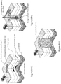
- FIG. 8 (a to c) is a schematic representation of a method for soil treatment according to the present FeS-ZVI-Electron Donor formulation comprising ferrous-sulfide when introduced below the earth's surface, thereby illustrating another example application of FeS-ZVI-electron donor formulation during in situ soil remediation, in accordance with an embodiment of the present disclosure.
- FIG. 8 may be categorized as follows:
- FIG. 8 a illustrates progression of the contaminant into sub-surface and migration onto specific-layers with respect to bed-rock, water-table, and ground water-flow.
- FIG. 8 b shows FeS-ZVI-electron donor application upon drilling operation.
- FIG. 8 c depicts a complete installation of treated soil columns.
- FeS ferrous sulfide
- PCE Tetrachloroethene
- TCE trichloroethene
- DCE 1,1-dichloroethene
- the present subject matter at least refers to co-injecting a mixture of organic hydrogen donors and iron sulfide-based reagents for remediation. Further, the present subject matter describes a Zero-Valent Metal and FeS based suspension with a liquid organic carbon for Water Remediation.
- FIG. 4 illustrates a schematic-representation of FeS transformation products by various environmental-species during remediation
- the description of FIG. 6 , FIG. 7 and FIG. 8 describe methods for accelerated in-situ chemical reduction of subsoil matter.
- the method comprises the steps of supplying a mixture comprising ferrous sulfide and an organic hydrogen donor into soil pathways to biologically react with dissolved contaminates in the groundwater.
- the contaminates to be targeted may be at least one of chlorinated solvents, haloalkanes, perchlorate, energetics, Energetics (DNT, HMX, Nitroglycerine, Perchlorate, RDX, and TNT), uranium, chromium.
- the ferrous sulfide is at least one of: iron sulfide, iron sulfide, iron(II) sulfide, ferrous sulfide, iron sulfide, iron sulfide or iron(II) sulfide, Mackinawite structured iron sulfide-based reagents, etc.
- the method supplying an organic hydrogen donor into the soil pathways to produce anerobic conditions to cause indigenous anaerobic bacteria to biodegrade residual concentrations of the contaminates.
- the organic hydrogen donor are low-molecular-weight organic compounds comprising at least one of lactate, acetate, methanol, formate, glycerol, glucose and combinations thereof.
- the organic hydrogen donor may be one or more of high-molecular-weight organic compounds C 4 -C 22 vegetable oil selected from the group consisting of soybean oil, coconut oil, rapeseed (canola) oil, peanut oil, crambe oil, sunflower oil and combinations thereof.
- the present method steps may be implemented through a gas- or liquid-based, closed delivery system.
- Injection points are advanced via traditional direct push technology or may be permanently installed injection wells (as also depicted in FIG. 7 and corresponding description).
- the gas is introduced at a pressure of approximately 175 psi such that delivery pathways and voids are established. Pathway development may be verified through state of the art mechanisms, i.e. by observing a substantial pressure-drop at the surface monitoring point. Gas introduction is immediately halted once the pressure drop is detected.
- next stage corresponds to injection of a mixture comprising the ferrous sulfide.
- the mixture may further comprise organic hydrogen donor, nutrients and micronutrients.
- a solution of ferrous sulfide, organic hydrogen donor and nutrients is immediately injected into the subsurface pathways.
- FeS reduces concentrations of dissolved-phase CVOCs and provides rapidly generated hydrogen, hydroxides and as a result causes overall microbial stimulation and biofilm-formation.
- An anaerobic organic hydrogen source is also injected during or immediately after the FeS injection to provide a slow release hydrogen source for the anaerobic dechlorination of the CVOCs.
- Vitamin B12 and riboflavin B2 can be mixed with the anaerobic stimulating hydrogen source to provide essential micro enzymes at the anaerobic sites.
- Organic hydrogen donor allows sustaining anaerobic conditions and provides hydrogen for dehalo-elimination processes that detoxify CVOCs or allow other anaerobic remediation processes.
- Nutrients, injected as organic ammonia and ortho-phosphate, are required for the maintenance of the microbial metabolic pathways, ATP/ADP synthesis and organelle development.
- Stage 3 is optional in nature and corresponds to a reinjection or second time injection of the mixture of Stage 2.
- the gas injection of Stage 1 may also be optionally repeated as a part of present stage 3. Such re-injection of mixtures and gases may be performed to clear the injection lines and to enhance in-situ mixing and greater penetration of the anaerobic stimulating products into soil.
- FIG. 4 illustrates a schematic representation of FeS transformation products by various environmental species during remediation.
- the representation in FIG. 4 corresponds to the figure published by Lan, Ying, Ph.D. dissertation, University of Oklahoma, 2016.
- the ferrous sulfide as forming a part of the mixture of the current invention is a highly reactive phase and applied to the treatment of groundwater contaminants, such as heavy metals, chlorinated aliphatic contaminants, arsenic (As) and selenium (Se) (Gong et al., 2016).
- groundwater contaminants such as heavy metals, chlorinated aliphatic contaminants, arsenic (As) and selenium (Se)
- FeS can remove mercury (Hg) through adsorption, precipitation of HgS, as well as the formation of surface complexes (Jeong et al., 2007).
- Chromium (Cr) (VI) can be reduced by FeS to Cr(III), which is insoluble and less toxic compared to Cr(VI), accompanied by the formation of greigite and an Fe(III) and Cr(III) hydroxide layer on the FeS surface (Mullet et al., 2004). FeS can also react with inorganic oxyanions, such as As and Se.
- the removal of As(III) may be achieved through the precipitation of AsS (Han et al., 2011b) or FeAsS (Bostick and Fendorf, 2003) at low pH values; whereas, as the pH increases, the As(III) is removed mainly through surface sorption (Han et al., 2011b).
- FeS is oxidized into greigite (Gallegos et al., 2008). Formation of outer sphere surface complexation may be a predominant mechanism of As(V) removal by FeS in aqueous solution (Farquhar et al., 2002; Wolthers et al., 2005). Sorption and reduction may also be important mechanisms of the removal of Se by FeS from aqueous solution, and FeSe is found on the FeS surface (Breynaert et al., 2008; Han et al., 2011a). Overall, the FeS-associated products during the reactions with heavy metals and inorganic oxyanions are greigite, sulfide precipitates, and iron (hydr)oxides layers on the FeS surface.
- Chlorinated aliphatic contaminants comprise Tetrachloroethylene (PCE), trichloroethylene (TCE) and carbon tetrachloride (CT) as the most frequently detected Chlorinated Aliphatic Contaminants or volatile organic compounds.
- FeS causes abiotic dechlorination of CT, TCE, and PCE.
- the products during the dechlorination may be sulfide precipitates, and iron (hydr)oxides layers on the FeS surface.
- the present subject matter at least illustrates a combined suspension of ferrous sulfide, zero-valent metal and organic hydrogen donor liquids. More specifically, a composition for a FeS, zero-valent metal and organic electron donor suspension is disclosed.
- the composition comprises a) a ferrous sulfide, b) a particulate zero-valent metal; c) a surfactant; d) a vegetable oil; and e) a thickening agent.
- the ferrous sulfide may be iron sulfide, iron sulfide, iron(II) sulfide, ferrous sulfide, iron sulfide, iron sulfide or iron(II) sulfide, Mackinawite structured iron sulfide-based reagents.
- the ferrous sulfide is present within the suspension in an amount ranging from 0.05 to 15.0% by weight.
- the microscale Mackinawite structured iron sulfide-based reagents are 1 to 45 microns in diameter, preferably an average particle size (D50) of 10 microns or less.
- the zero-valent metal particles are a plurality of microscale zero-valent metal particles, preferably an iron-based powder.
- Said plurality of microscale zero-valent iron particles are 1-45 microns in diameter, preferably an average particle size (D50) of 10 microns or less.
- the microscale zero-valent iron (ZVI) particle comprises an acid-washed iron-based powder.
- the apparent density of the acid-washed iron-based powder is 0.5 to 5 g/cm 3 , preferably 1 to 2 g/cm 3 .
- the iron-based powder has Fe-content of at least 90% by weight and is a hydrogen-reduced iron powder.
- Such iron-based powder BET Brunauer, Emmett and Teller
- the iron-based powder is present in an amount ranging from 0.05 to 45.0% by weight.
- the ZVI (powered metal) may be obtained from sponge iron or atomized iron, which are in turn obtained from treatment, reduction, regrinding, etc.
- the ZVI (powdered metal) may be obtained from waste material like steel mill waste (Kesavan and Azad, 2008). Steel industry waste like dust from Blast Furnace (Shen et al., 2013) and pickling waste liquor (Fang et al., 2011) has been known to be used for preparation of powdered ZVI.
- the sludge produced in the steel industry, from the Basic Oxygen Furnace (BOF) has high percentage of iron and may be chosen as the starting material for the production of powdered ZVI.
- the surfactant is Aerosol OT and present in the amount ranging from 0.05 to 1.0% by weight.
- surfactants include Fatty acid sulfonates (the most common of which is sodium lauryl sulfate, or SLS), Ethoxylated compounds, such as ethoxylated propylene glycol, Lecithin, Polygluconates, Quaternary ammonium fatty acid adducts (aka ammonium quats, used as fabric softeners), Lignin sulfonates, etc.
- the vegetable oil is a C 4 -C 22 oil selected from the group consisting of soybean oil, corn oil, coconut oil, canola oil, peanut oil, sunflower oil, olive oil, garlic oil, crambe oil, rapeseed oil and mixtures thereof.
- the oil is present in the amount ranging from 33 to 63% by weight.
- the thickening agent is propylene glycol and present in the amount ranging from 21 to 41% by weight.
- the zero-valent metal suspension is a ferrous sulfide and zero-valent iron (ZVI) based suspension, interchangeably referred as FeS-ZVI suspension or FeS-ZVI formulation.
- the suspension comprises about 41 wt. % of zero-valent iron particles and 0.05 to 15.0 wt. % of Mackinawite structured iron sulfide-based reagents.
- the zero-valent iron may be a uniquely engineered media that has extremely high-porosity, surface area and reactivity, providing exceptional performance.
- the size of present ZVI particles is about 1-18 micron (diameter) for propagation into the majority of porous media.
- microscale Mackinawite structured iron sulfide-based reagents is 1 to 45 microns in diameter, preferably an average particle size (D50) of 10 microns or less.
- D50 average particle size
- the present ZVI has much higher reactivity and a surface-area than a conventional carbonyl-iron, less-dose is required and the degradation rate of TCE is much faster.
- the FeS-ZVI suspension can at-least reduce remediation time and provide better longevity for increased-reliability and reduction of injection.
- the FeS-ZVI suspension further comprises about 36 by wt % of soybean oil.
- the 36% by weight of Soybean oil in the suspension is selected as a long-lasting source of carbon and hydrogen required for enhanced reductive de-chlorination and other bioremediation processes. It also serves as a fermentable substrate to create favorable aquifer conditions for anaerobic remediation and provide electrons for extended time.
- the soybean oil is refined, bleached, and deodorized (RBD) soybean oil.
- the composition further comprises about 23% of propylene-glycol (PG) as an oil thickening agent.
- PG propylene-glycol
- the PG may be color-less and able to depress the freezing point of water when mixed with groundwater.
- PG is also non-corrosive, has very low volatility and very low toxicity.
- PG is used as a thickener because it serves as a cross-linker between soybean molecules and FeS/ZVI particles, giving the latter a positive buoyancy effect.
- the composition further comprises about 0.1% surfactant, wherein said surfactant is dioctyl sodium sulfosuccinate (AOT).
- AOT dioctyl sodium sulfosuccinate
- the FeS-ZVI suspension is a reactive-system comprising a food-grade vegetable oil, an oil-thickening agent, and a surfactant that suspend reactive FeS particles, ZVI or other metal particles.
- Such suspension comprises a liquid membrane formed of the food-grade vegetable oil encapsulating the FeS and ZVI particles as a part of the suspension-network.
- the present matter further illustrates a method for preparing suspension of FeS and zero-valent iron particles in non-aqueous media.
- the method comprises:
- FIG. 5 illustrates a suspension network comprising the combination of soybean oil, PG and AOT as the continuous phase or oil phase.
- the ZVI and FeS particles constitute the dispersant phase.
- the suspension into oil phase at least leads to an increased steric repulsion among the ZVI and FeS particles, while ensuring least increase in viscosity.
- the surfactant and oil thickener within the suspension lead to increase in positive-buoyancy.
- the FeS-ZVI suspension illustrated by the present subject matter includes long lasting electron donors (soybean oil) and quick release electron donors (PG).
- the in situ chemical reduction (ISCR) is carried out.
- the present FeS-ZVI is advantageously used for ISCR.
- ISCR is a remediation technique that combines both biological processes and FeS and/or ZVI particle-driven abiotic pathways to chemically reduce persistent organic compounds such as chlorinated solvents, pesticides and energetics into harmless end products.
- the incorporation of FeS and ZVI enhances chlorinated contaminant remediation by enabling various chemical reduction pathways including the abiotic pathways represented in FIG. 4 .
- the present FeS-ZVI suspension is suitable for the dechlorination of trichoroethene (TCE), which can be in the form of a dense non-aqueous phase liquid (DNAPL).
- TCE trichoroethene
- DNAPLs in the subsurface can act as a source of groundwater contamination. TCE and other contaminants in the form of DNAPL may likewise be remediated using the present suspension.
- DNAPL can diffuse into the oil phase of the ZVI suspension, whereupon it reaches the surface of the zero-valent metal particles and activates a dehalogenation process.
- a hydrocarbon reaction by-product of the dehalogenation reaction for example ethene, diffuses out of the suspension and vents to the aquifer.
- DNAPL and contaminants in other phases in the subsurface may become exposed to the FeS-ZVI suspension in a variety of ways.
- the likely location of the DNAPL is defined, as illustrated through the example provided under FIG. 7 .
- an FeS-ZVI emulsion is delivered in-situ to contamination pools via a system of at least one injection well as illustrated by example implementations provided in FIG. 7 .
- Injection wells can be permanent structures left in the ground for repeatedly injecting the FeS-ZVI suspension into the ground.
- the injection wells may contain screen portions through which the FeS-ZVI suspension may pass in order to flow into the subsurface and stay in the vicinity or contact the DNAPL phase.
- FeS-ZVI suspension may be injected into the DNAPL-impacted aquifer by jetting the fluid through hollow rods that are hammered into the ground using commonly called “direct push” technology.
- Direct Push machines “push” tools and sensors into the ground without the use of drilling to remove soil to make a path for the tool.
- a distal portion of the push rods has a series of holes along its length from where the FeS-ZVI suspension flows as it is jetted into the native matrix or subsurface aquifer material.
- the push rods are advanced further into the soil to cover the vertical extent and depth of the contamination.
- the FeS-ZVI Suspension can be directly mixed with contaminated soils. It can also be used to create a permeable reactive barrier (e.g. as depicted in FIG. 6 ) by filling a trench with FeS-ZVI suspension or by injecting sufficient FeS-ZVI suspension along a path perpendicular to the expected flow of contaminated groundwater. (As illustrated in FIG. 7 ).
- FIGS. 6 to 8 relate to example implementations of ISCR comprising the use of FeS-ZVI suspension in the permeable reactive barriers (PRB); direct injection and direct mixing of the FeS-ZVI suspension into aquifer material for soil and groundwater remediation; and use of FeS-ZVI suspension in fixed bed reactors or filters for treatment of contaminated water.
- PRB permeable reactive barriers
- FIG. 6 is a schematic representation of a method for treating groundwater using a permeable reactive barrier (PRB) and thereby representing example application for the present FeS-ZVI formulation during groundwater remediation.
- the FeS-ZVI suspension can be used in permeable reactive barriers (PRBs) for groundwater treatment.
- PRBs permeable reactive barriers
- FIG. 6 the permeable reactive barrier ( 18 ) of the FeS-ZVI suspension according to the present subject matter is placed downgradient of the contaminated zone.
- Low permeability funnel structures ( 15 , 16 ) may be emplaced to direct the plume of contaminated water ( 20 ) toward the PRB ( 18 ).
- the freed-of-contaminant water continues to naturally flow as shown in arrows ( 22 ).
- the aquifer downgradient of the PRB ( 24 ) is thus cleaned of contaminants.
- FIG. 6 a that corresponds to previously referred FIG. 3 b , is an enlarged schematic representation of contaminated water contacting particle of the FeS-ZVI suspension according to the present subject matter used in the PRB ( 18 ).
- FIG. 7 is a schematic representation of a method for groundwater-treatment according to the present FeS-ZVI formulation when introduced into the groundwater via an injection well, thereby illustrating another example application of FeS-ZVI formulation during ground water remediation, in accordance with an embodiment of the present disclosure.
- Table 2 enumerates various components present therein alongside the reference numerals.
- an injection point ( 36 ) is provided upstream of a monitoring or extraction well ( 40 ) potentially used to retrieve groundwater for human use.
- the injection well ( 36 ) is drilled or dug so it intercepts the groundwater containing contaminants.
- Groundwater flows in the direction represented by arrow ( 32 ).
- the aquifer becomes contaminated as a contaminant source ( 30 ) typically originates on the surface and flows downward through soils until it reaches the water table ( 31 ).
- Contaminants ( 30 ) enter aquifer and move both downwards as DNAPLs and in the direction of groundwater flow as dissolved phase contamination to form a contaminated groundwater plume ( 34 ).
- FIG. 7 a which refers to FIG. 3 b , is an enlarged schematic representation of a contaminated-water contacting particle of the FeS-ZVI suspension that has been injected into the ground through the point ( 36 ).
- one injection-point is advanced into said aquifer.
- the injection may be performed by a technique selected from one or more of at least one push-rod, at said at least one injection-point, an injection through well, a French drain type system, deep tilling, an hydraulic-injection, a multi-phase inert gas injection, an aerosol injection, a water injection, at least one pump, at least one blower, at least one compressor, tank, at least one tank of compressed gas, at least one compressed gas tank after a blower or compressor, a direct push rig, at least one hand-held injection rod, and a combination of one or more aforesaid techniques.
- the introduction of FeS-ZVI formulation is performed at a pressure between approximately 10 psi and approximately 1,000 psi.
- FIG. 8 (a to c) is a schematic-representation of a method for soil-treatment according to the present FeS-ZVI formulation when introduced below the earth's surface, thereby illustrating another example application of FeS-ZVI formulation during in-situ soil remediation, in accordance with an embodiment of the present-disclosure. More specifically, the present FIG. 8 is a conceptual-model depicting FeS-ZVI and Clay soil-mixing as an in situ remediation technology for remediation of chlorinated dense non-aqueous phase liquids (DNAPLs).
- DNAPLs chlorinated dense non-aqueous phase liquids
- FIG. 8 a illustrates a heterogeneous subsurface before soil-mixing and thereby depicts a footprint of contaminated soils. More specifically, FIG. 8 a illustrates progression of the contaminant into sub-surface and migration onto specific-layers with respect to bed-rock, water-table, and ground water-flow.
- FIG. 8 b illustrates the FeS-ZVI application upon drilling operation and thereby depicts the process of soil-mixing using augers or special tools to mechanically-mix the soil with FeS-ZVI. The process simultaneously breaks up the soil without removing it, injects the FeS-ZVI at low pressure and thoroughly mixes the FeS-ZVI with the soil. Single or multiple mixing tools (auger, blades, rotary head) are used to directly inject ZVI into the mixing zones.
- the present mechanism combines abiotic-degradation (via FeS, zero-valent iron, ZVI, addition) and immobilization (via soil-mixing and clay-addition).
- the FeS-ZVI clay soil-mixing technology provides a delivery-mechanism that mechanically reduces subsurface heterogeneities.
- FIG. 8 c depicts a complete-installation of treated soil columns and thereby illustrates a homogenized low-permeable subsurface after soil-mixing with bypassing groundwater, thereby depicting treated soil-columns.
- the FeS-ZVI clay soil-mixing technology at least proves efficient for source mass depletion in the presence of DNAPL
- the FeS-ZVI suspension has been proven to effectively degrade halogenated solvents.
- the half reaction of (Fe 0 ) to (Fe +2 ) (Equation 1) has a reduction-potential of ⁇ 0.440V.
- the reductive dechlorination activity of ZVI is governed by the iron surface components and properties.
- anaerobic dechlorination (Equation 3) and hydrolysis (Equation 4) are usually accompanied with pH increase and ferrous ions accumulation.
- Hydrogen-peroxide formed as a result of reduction of oxygen reacts with accumulated ferrous-ions (i.e. Fe +2 ) to form Fe +3 and hydroxyl radicals that are highly reactive oxidants to degrade aqueous phase TCE and/or oxidize TCE in the presence of the soil.
- ZVI can react directly with sulfate via abiotic reaction (Equation 5). More significantly, ZVI reacts with water to produce H 2 and ferrous iron (Equation 6), after which sulfate is reduced by H 2 to sulfide via microbially-mediated reactions and forms iron sulfide precipitates (Equation 7) Fe 0 (S)+1 ⁇ 4SO 4 2 ⁇ b +2 H+ ⁇ 1 ⁇ 4FeS(S)+3 ⁇ 4Fe 2+ +10 H 2 O (5) Fe 0 (S)+2H 2 O ⁇ Fe 2+ +H 2 +2OH ⁇ (6) 2Fe 2+ +SO 4 2 ⁇ +4H 2 ⁇ Fe S(S)+4H 2 O (7)
- in situ biogeochemical transformation refers to processes in which contaminants are degraded by abiotic-reactions with minerals formed that are either naturally occurring or are biogenically produced in the subsurface.
- Natural aquifer systems are complex ecosystems with a plethora of microbial-communities. Such microbial-communities are subject to a wide variety of changes as the environment of the aquifer is altered.
- the present FeS-ZVI formulation may be used to take advantage of the degradation capabilities of these microbial communities for a synergistic-degradation effect of target contaminants present in the aquifer.
- the added organic substrates are first fermented to hydrogen (H 2 ) and low-molecular weight fatty acids. These short-chain molecules, such as acetate, lactate, propionate, and butyrate, in turn provide carbon and energy for anaerobic bioremediation.
- the substrates may be categorized into four types: soluble substrates, viscous or low viscosity substrates, solid substrates, and miscellaneous experimental substrates. All of these substrates are biodegraded and ultimately yield hydrogen.
- the present FeS-ZVI suspension formulation is such that the iron particles will suffer limited corrosion and limited exposure to water and oxygen during packaging, transport and storage. Corrosion on FeS and ZVI prior to its intended use decreases its cleaning performance. However, the present suspension offers logistical, economic and performance advantages, as the formulation protects the iron particles from corrosion until it is applied and used for remediation.
- the present FeS-ZVI suspension is a stable suspension and free from the constraints of particle agglomeration, sedimentation and deposition as otherwise suffered by conventional ZVI based compositions.
- Such an improvement at-least facilitates an ease of logistics that accomplishes a dual purpose of single stage treatment in field operations and safe transportation for FeS and ZVI particles.
- Mixing amendments from different sources to prepare fluid systems in the field for remedial processes drastically increases logistical issues and complexity for any field projects and is much-less favourable for environmental clean-up operations.
- the present FeS-ZVI suspension formulation provides significant improvements and synergism from the benefits of soybean oil (as a long lasting electron donor for biological treatment of contaminants) and propylene glycol (a quick release electron donor for biological treatment of contaminants).
- the present FeS-ZVI suspension scores over the conventional ZVI formulations and applications at least based on presence of long lasting electron donors, quick release electron donors, corrosion-free environment during packaging, ease of logistics (single stage and easy to handle final product).
- any disjunctive word or phrase presenting two or more alternative terms, whether in the description, claims, or drawings, should be understood to contemplate the possibilities of including one of the terms, either of the terms, or both terms.
- the phrase “A or B” should be understood to include the possibilities of “A” or “B” or “A and B.”
Landscapes
- Chemical & Material Sciences (AREA)
- Engineering & Computer Science (AREA)
- Life Sciences & Earth Sciences (AREA)
- Organic Chemistry (AREA)
- Environmental & Geological Engineering (AREA)
- Soil Sciences (AREA)
- Chemical Kinetics & Catalysis (AREA)
- Analytical Chemistry (AREA)
- Inorganic Chemistry (AREA)
- Hydrology & Water Resources (AREA)
- Water Supply & Treatment (AREA)
- Materials Engineering (AREA)
- Processing Of Solid Wastes (AREA)
Abstract
Description
C2HCl3+4FeO0+5H+→C2H6+4Fe2++3Cl−
-
- a) preparing a non-aqueous solution by mixing an oil-thickener of about 21 to 41% by weight into a vegetable oil of about 33 to 63% by weight.
- b) Thereafter, a surfactant of about 0.05 to 1.0% by weight is dissolved into the solution.
- c) A suspension of ZVI particles into a non-aqueous phase is prepared by mixing about 0.05 to 45.0% by weight of the ZVI particles into the non-aqueous solution.
- d) Mackinawite structured iron sulfide-based reagents of about 0.05 to 15.0% by weight are further added to thereby result in a FeS-ZVI based suspension
| TABLE 1 | ||
| Reference | Components | |
| 18 | Permeable |
|
| 15, 16 | Permeability funnel structures | |
| 20 | A plume of |
|
| 21 | Arrow defining direction of | |
| plume | ||
| 22 | Arrow defining direction of flow of water freed | |
| of contaminant within the |
||
| 24 | Water plume or flow cleaned of contaminants | |
| TABLE 2 | ||
| Reference | Components | |
| 36 | An |
|
| 40 | An injection, extraction or monitoring well | |
| 31 | Water Table | |
| 32 | Arrow defining direction of |
|
| 30 | |
|
| 34 | Plume of contaminated |
|
| 38 | Injection Device | |
Fe0---->Fe2++2e − (1)
R—Cl+2e −+H+--->R—H+Cl− (2)
Fe0+R—Cl+H+-->Fe2++R—H+Cl− (3)
Fe0+2H+→Fe2++H2 (4)
Fe0(S)+¼SO4 2−b +2H+→¼FeS(S)+¾Fe2++10 H2O (5)
Fe0(S)+2H2O→Fe2++H2+2OH− (6)
2Fe2++SO4 2−+4H2→Fe S(S)+4H2O (7)
Claims (38)
Priority Applications (1)
| Application Number | Priority Date | Filing Date | Title |
|---|---|---|---|
| US16/585,862 US11123779B2 (en) | 2019-02-18 | 2019-09-27 | Method and a chemical composition for accelerated in situ biochemical remediation |
Applications Claiming Priority (2)
| Application Number | Priority Date | Filing Date | Title |
|---|---|---|---|
| US16/278,328 US11491522B2 (en) | 2019-02-18 | 2019-02-18 | Zero-valent metal suspension in non-aqueous phase for water remediation |
| US16/585,862 US11123779B2 (en) | 2019-02-18 | 2019-09-27 | Method and a chemical composition for accelerated in situ biochemical remediation |
Related Parent Applications (1)
| Application Number | Title | Priority Date | Filing Date |
|---|---|---|---|
| US16/278,328 Continuation-In-Part US11491522B2 (en) | 2019-02-18 | 2019-02-18 | Zero-valent metal suspension in non-aqueous phase for water remediation |
Publications (2)
| Publication Number | Publication Date |
|---|---|
| US20200261954A1 US20200261954A1 (en) | 2020-08-20 |
| US11123779B2 true US11123779B2 (en) | 2021-09-21 |
Family
ID=72043269
Family Applications (1)
| Application Number | Title | Priority Date | Filing Date |
|---|---|---|---|
| US16/585,862 Active US11123779B2 (en) | 2019-02-18 | 2019-09-27 | Method and a chemical composition for accelerated in situ biochemical remediation |
Country Status (1)
| Country | Link |
|---|---|
| US (1) | US11123779B2 (en) |
Families Citing this family (9)
| Publication number | Priority date | Publication date | Assignee | Title |
|---|---|---|---|---|
| US11123779B2 (en) | 2019-02-18 | 2021-09-21 | Tersus Environmental Llc | Method and a chemical composition for accelerated in situ biochemical remediation |
| US11491522B2 (en) | 2019-02-18 | 2022-11-08 | Tersus Environmental Llc | Zero-valent metal suspension in non-aqueous phase for water remediation |
| CN112974504B (en) * | 2021-01-20 | 2021-10-19 | 中国环境科学研究院 | In-situ reduction targeted injection repair method for difficult-to-oxidize organic contaminated site |
| US20220234919A1 (en) * | 2021-01-25 | 2022-07-28 | Höganäs Ab (Publ) | Iron-comprising concentrate for preparation of in situ remediation solution |
| CN113102761B (en) * | 2021-03-01 | 2022-08-05 | 同济大学 | Method for preparing composite zero-valent iron material based on soluble sulfide wet ball milling |
| CN114538556B (en) * | 2022-02-24 | 2023-12-26 | 中南大学 | Porous FeS material, preparation method thereof and application thereof in purification of arsenic-containing and/or heavy metal-containing wastewater |
| CN117776368A (en) * | 2023-11-15 | 2024-03-29 | 同济大学 | Method for degrading polycyclic aromatic hydrocarbon by activating oxygen through micro-nano bubble synergistic ferrous sulfide |
| CN118341386B (en) * | 2024-04-30 | 2025-10-10 | 华南理工大学 | Sulfided micron zero-valent iron and its preparation method and application |
| CN120757220B (en) * | 2025-06-13 | 2026-02-27 | 中国海洋大学 | Methods for optimizing the reduction efficiency of trichloroethylene by in-situ biosulfurization zero-valent iron |
Citations (15)
| Publication number | Priority date | Publication date | Assignee | Title |
|---|---|---|---|---|
| US20010042723A1 (en) * | 1999-02-25 | 2001-11-22 | Sivavec Timothy Mark | Composition and method for treating aqueous composition contaminants |
| US6664298B1 (en) * | 2001-10-02 | 2003-12-16 | The United States Of America As Represented By The Administrator Of The National Aeronautics & Space Administration | Zero-valent metal emulsion for reductive dehalogenation of DNAPLs |
| US20040007524A1 (en) | 2002-07-12 | 2004-01-15 | Scott Noland | Compositions for removing hydrocarbons and halogenated hydrocarbons from contaminated environments |
| US20050006306A1 (en) * | 2002-07-12 | 2005-01-13 | Scott Noland | Compositions for removing halogenated hydrocarbons from contaminated environments |
| US6906235B2 (en) * | 2001-01-26 | 2005-06-14 | Tosoh Corporation | Iron sulfide mixtures; iron sulfide heavy metal treating agents; and methods of treating using such agents |
| US7128841B2 (en) * | 2004-03-11 | 2006-10-31 | Lehigh University | Dispersed zero-valent iron colloids |
| US20070225542A1 (en) * | 2005-11-02 | 2007-09-27 | Higgins Thomas E | Treatment of in ground chromium ore processing residue |
| US20080272051A1 (en) | 2007-05-04 | 2008-11-06 | Shireen Baseeth | Compositions and Uses Thereof in Bioremediation |
| US7611637B2 (en) | 2003-08-06 | 2009-11-03 | Lehigh University | Method for treating contaminated water |
| US20160289106A1 (en) | 2015-04-03 | 2016-10-06 | Onmaterials, Llc | Emulsion systems and methods for delivery of in-situ remediation amendments |
| US20180099877A1 (en) | 2016-10-06 | 2018-04-12 | Höganäs Ab (Publ) | Iron based media |
| US20200031695A1 (en) * | 2018-07-26 | 2020-01-30 | The Royal Institution For The Advancement Of Learning/Mcgill University | Sulfidated nanoscale zerovalent iron and method of use thereof |
| US20200038926A1 (en) * | 2018-08-01 | 2020-02-06 | Regenesis Bioremediation Products | Compositions and methods for removing chlorinated hydrocarbons |
| US20200261954A1 (en) | 2019-02-18 | 2020-08-20 | Tersus Environmental Llc | Method and a chemical composition for accelerated in situ biochemical remediation |
| US20200261953A1 (en) | 2019-02-18 | 2020-08-20 | Tersus Environmental Llc | Zero-valent metal suspension in non-aqueous phase for water remediation |
-
2019
- 2019-09-27 US US16/585,862 patent/US11123779B2/en active Active
Patent Citations (17)
| Publication number | Priority date | Publication date | Assignee | Title |
|---|---|---|---|---|
| US20010042723A1 (en) * | 1999-02-25 | 2001-11-22 | Sivavec Timothy Mark | Composition and method for treating aqueous composition contaminants |
| US6906235B2 (en) * | 2001-01-26 | 2005-06-14 | Tosoh Corporation | Iron sulfide mixtures; iron sulfide heavy metal treating agents; and methods of treating using such agents |
| US6664298B1 (en) * | 2001-10-02 | 2003-12-16 | The United States Of America As Represented By The Administrator Of The National Aeronautics & Space Administration | Zero-valent metal emulsion for reductive dehalogenation of DNAPLs |
| US7037946B1 (en) | 2001-10-02 | 2006-05-02 | The United States Of America As Represented By The Administrator Of The National Aeronautics And Space Administration | Zero-valent metal emulsion for reductive dehalogenation of DNAPLs |
| US9352987B2 (en) * | 2002-07-12 | 2016-05-31 | Remediation Products, Inc. | Method of manufacturing compositions for removing halogenated hydrocarbons from contaminated environments |
| US20040007524A1 (en) | 2002-07-12 | 2004-01-15 | Scott Noland | Compositions for removing hydrocarbons and halogenated hydrocarbons from contaminated environments |
| US20050006306A1 (en) * | 2002-07-12 | 2005-01-13 | Scott Noland | Compositions for removing halogenated hydrocarbons from contaminated environments |
| US7611637B2 (en) | 2003-08-06 | 2009-11-03 | Lehigh University | Method for treating contaminated water |
| US7128841B2 (en) * | 2004-03-11 | 2006-10-31 | Lehigh University | Dispersed zero-valent iron colloids |
| US20070225542A1 (en) * | 2005-11-02 | 2007-09-27 | Higgins Thomas E | Treatment of in ground chromium ore processing residue |
| US20080272051A1 (en) | 2007-05-04 | 2008-11-06 | Shireen Baseeth | Compositions and Uses Thereof in Bioremediation |
| US20160289106A1 (en) | 2015-04-03 | 2016-10-06 | Onmaterials, Llc | Emulsion systems and methods for delivery of in-situ remediation amendments |
| US20180099877A1 (en) | 2016-10-06 | 2018-04-12 | Höganäs Ab (Publ) | Iron based media |
| US20200031695A1 (en) * | 2018-07-26 | 2020-01-30 | The Royal Institution For The Advancement Of Learning/Mcgill University | Sulfidated nanoscale zerovalent iron and method of use thereof |
| US20200038926A1 (en) * | 2018-08-01 | 2020-02-06 | Regenesis Bioremediation Products | Compositions and methods for removing chlorinated hydrocarbons |
| US20200261954A1 (en) | 2019-02-18 | 2020-08-20 | Tersus Environmental Llc | Method and a chemical composition for accelerated in situ biochemical remediation |
| US20200261953A1 (en) | 2019-02-18 | 2020-08-20 | Tersus Environmental Llc | Zero-valent metal suspension in non-aqueous phase for water remediation |
Non-Patent Citations (5)
| Title |
|---|
| Gu et al., "Mechanochemically Sulfidated Microscale Zero Valent Iron: Pathways, Kinetics, Mechanism, and Efficiency of Trichloroethylene Dechlorination," Environ. Sci. Technol. 51:12653-12662, 2017. |
| Lan, "Characterization of the Iron Sulfide Oxidation Products Formed During Reductive Dechlorination of Chlorinated Aliphatic Contaminants," University of Oklahoma, Dissertation, 2016. |
| Lan, "Controlled Sulfidation to Optimize the Remediation Performance of Zerovalent Iron and Related Materials," Tersus 2018 Webinar Series, Jun. 21, 2018. |
| Su et al., "Chapter 9: Sulfide-Modified NZVI (S-NZVI): Synthesis, Characterization, and Reactivity," Nanoscale Zerovalent Iron Particles for Environmental Restoration, Springer International Publishing AG 2019, pp. 359-386. |
| Yang, Z., Xu, H., Shan, C., Jiang, Z., Pan, B., Effects of brining on the corrosion of ZVI and its subsequent As(III/V) and Se(IV/VI) removal from water, Chemosphere (2017), doi: 10.1016/j.chemosphere.2016.12.029. |
Also Published As
| Publication number | Publication date |
|---|---|
| US20200261954A1 (en) | 2020-08-20 |
Similar Documents
| Publication | Publication Date | Title |
|---|---|---|
| US11123779B2 (en) | Method and a chemical composition for accelerated in situ biochemical remediation | |
| EP1521723B2 (en) | Compositions for removing hydrocarbons and halogenated hydrocarbons from contaminated environments | |
| US12103057B2 (en) | Zero-valent metal suspension in non-aqueous phase for water remediation | |
| US10000394B2 (en) | Compositions for removing hydrocarbons and halogenated hydrocarbons from contaminated environments | |
| US7708496B2 (en) | In-situ surfactant and chemical oxidant flushing for complete remediation of contaminants and methods of using same | |
| US20100185039A1 (en) | Method for extraction and surfactant enhanced subsurface contaminant recovery | |
| WO2014182572A2 (en) | Chemical oxidation and biological attenuation process for the treatment of contaminated media | |
| Mohammed et al. | Application of soil washing treatment method for the remediation of petroleum polluted soil | |
| Kao et al. | Application of slow-release materials for in situ and passive remediation of contaminated groundwater | |
| Nwachukwu | Prospective techniques for in-situ treatment and protection of aquifers: A sustainable hydrology review | |
| Santos et al. | In situ chemical oxidation (ISCO) | |
| Ojha et al. | Various remediation measures for groundwater contamination | |
| Salami et al. | Remediation of contaminated groundwater: an overview | |
| Phenrat et al. | Principles to Field-Scale Applications | |
| Banerjee et al. | Site remediation techniques in India: a review | |
| Snousy et al. | SDRP JOURNAL OF EARTH SCIENCES & ENVIRONMENTAL STUDIES (ISSN: 2472-6397) | |
| HK1077289B (en) | Compositions for removing hydrocarbons and halogenated hydrocarbons from contaminated environments |
Legal Events
| Date | Code | Title | Description |
|---|---|---|---|
| AS | Assignment |
Owner name: TERSUS ENVIRONMENTAL LLC, NORTH CAROLINA Free format text: ASSIGNMENT OF ASSIGNORS INTEREST;ASSIGNORS:ALDEN, DAVID F.;BIRK, GARY M.;BANG, SANGHO;AND OTHERS;SIGNING DATES FROM 20190924 TO 20190926;REEL/FRAME:050519/0307 |
|
| FEPP | Fee payment procedure |
Free format text: ENTITY STATUS SET TO UNDISCOUNTED (ORIGINAL EVENT CODE: BIG.); ENTITY STATUS OF PATENT OWNER: SMALL ENTITY |
|
| FEPP | Fee payment procedure |
Free format text: ENTITY STATUS SET TO SMALL (ORIGINAL EVENT CODE: SMAL); ENTITY STATUS OF PATENT OWNER: SMALL ENTITY |
|
| STPP | Information on status: patent application and granting procedure in general |
Free format text: NON FINAL ACTION MAILED |
|
| STPP | Information on status: patent application and granting procedure in general |
Free format text: NON FINAL ACTION MAILED |
|
| STPP | Information on status: patent application and granting procedure in general |
Free format text: RESPONSE TO NON-FINAL OFFICE ACTION ENTERED AND FORWARDED TO EXAMINER |
|
| STPP | Information on status: patent application and granting procedure in general |
Free format text: NOTICE OF ALLOWANCE MAILED -- APPLICATION RECEIVED IN OFFICE OF PUBLICATIONS |
|
| STPP | Information on status: patent application and granting procedure in general |
Free format text: NOTICE OF ALLOWANCE MAILED -- APPLICATION RECEIVED IN OFFICE OF PUBLICATIONS |
|
| STPP | Information on status: patent application and granting procedure in general |
Free format text: PUBLICATIONS -- ISSUE FEE PAYMENT VERIFIED |
|
| STCF | Information on status: patent grant |
Free format text: PATENTED CASE |
|
| MAFP | Maintenance fee payment |
Free format text: PAYMENT OF MAINTENANCE FEE, 4TH YR, SMALL ENTITY (ORIGINAL EVENT CODE: M2551); ENTITY STATUS OF PATENT OWNER: SMALL ENTITY Year of fee payment: 4 |