US11123598B2 - Exercise device - Google Patents
Exercise device Download PDFInfo
- Publication number
- US11123598B2 US11123598B2 US15/609,910 US201715609910A US11123598B2 US 11123598 B2 US11123598 B2 US 11123598B2 US 201715609910 A US201715609910 A US 201715609910A US 11123598 B2 US11123598 B2 US 11123598B2
- Authority
- US
- United States
- Prior art keywords
- crank
- arm
- pedal
- drive
- coupled
- Prior art date
- Legal status (The legal status is an assumption and is not a legal conclusion. Google has not performed a legal analysis and makes no representation as to the accuracy of the status listed.)
- Active, expires
Links
Images


Classifications
-
- A—HUMAN NECESSITIES
- A63—SPORTS; GAMES; AMUSEMENTS
- A63B—APPARATUS FOR PHYSICAL TRAINING, GYMNASTICS, SWIMMING, CLIMBING, OR FENCING; BALL GAMES; TRAINING EQUIPMENT
- A63B21/00—Exercising apparatus for developing or strengthening the muscles or joints of the body by working against a counterforce, with or without measuring devices
- A63B21/012—Exercising apparatus for developing or strengthening the muscles or joints of the body by working against a counterforce, with or without measuring devices using frictional force-resisters
- A63B21/015—Exercising apparatus for developing or strengthening the muscles or joints of the body by working against a counterforce, with or without measuring devices using frictional force-resisters including rotating or oscillating elements rubbing against fixed elements
-
- A—HUMAN NECESSITIES
- A63—SPORTS; GAMES; AMUSEMENTS
- A63B—APPARATUS FOR PHYSICAL TRAINING, GYMNASTICS, SWIMMING, CLIMBING, OR FENCING; BALL GAMES; TRAINING EQUIPMENT
- A63B21/00—Exercising apparatus for developing or strengthening the muscles or joints of the body by working against a counterforce, with or without measuring devices
- A63B21/15—Arrangements for force transmissions
- A63B21/151—Using flexible elements for reciprocating movements, e.g. ropes or chains
- A63B21/154—Using flexible elements for reciprocating movements, e.g. ropes or chains using special pulley-assemblies
-
- A—HUMAN NECESSITIES
- A63—SPORTS; GAMES; AMUSEMENTS
- A63B—APPARATUS FOR PHYSICAL TRAINING, GYMNASTICS, SWIMMING, CLIMBING, OR FENCING; BALL GAMES; TRAINING EQUIPMENT
- A63B21/00—Exercising apparatus for developing or strengthening the muscles or joints of the body by working against a counterforce, with or without measuring devices
- A63B21/22—Resisting devices with rotary bodies
- A63B21/225—Resisting devices with rotary bodies with flywheels
-
- A—HUMAN NECESSITIES
- A63—SPORTS; GAMES; AMUSEMENTS
- A63B—APPARATUS FOR PHYSICAL TRAINING, GYMNASTICS, SWIMMING, CLIMBING, OR FENCING; BALL GAMES; TRAINING EQUIPMENT
- A63B21/00—Exercising apparatus for developing or strengthening the muscles or joints of the body by working against a counterforce, with or without measuring devices
- A63B21/40—Interfaces with the user related to strength training; Details thereof
- A63B21/4027—Specific exercise interfaces
- A63B21/4033—Handles, pedals, bars or platforms
- A63B21/4034—Handles, pedals, bars or platforms for operation by feet
-
- A—HUMAN NECESSITIES
- A63—SPORTS; GAMES; AMUSEMENTS
- A63B—APPARATUS FOR PHYSICAL TRAINING, GYMNASTICS, SWIMMING, CLIMBING, OR FENCING; BALL GAMES; TRAINING EQUIPMENT
- A63B21/00—Exercising apparatus for developing or strengthening the muscles or joints of the body by working against a counterforce, with or without measuring devices
- A63B21/40—Interfaces with the user related to strength training; Details thereof
- A63B21/4027—Specific exercise interfaces
- A63B21/4033—Handles, pedals, bars or platforms
- A63B21/4035—Handles, pedals, bars or platforms for operation by hand
-
- A—HUMAN NECESSITIES
- A63—SPORTS; GAMES; AMUSEMENTS
- A63B—APPARATUS FOR PHYSICAL TRAINING, GYMNASTICS, SWIMMING, CLIMBING, OR FENCING; BALL GAMES; TRAINING EQUIPMENT
- A63B22/00—Exercising apparatus specially adapted for conditioning the cardio-vascular system, for training agility or co-ordination of movements
- A63B22/0002—Exercising apparatus specially adapted for conditioning the cardio-vascular system, for training agility or co-ordination of movements involving an exercising of arms
- A63B22/001—Exercising apparatus specially adapted for conditioning the cardio-vascular system, for training agility or co-ordination of movements involving an exercising of arms by simultaneously exercising arms and legs, e.g. diagonally in anti-phase
-
- A—HUMAN NECESSITIES
- A63—SPORTS; GAMES; AMUSEMENTS
- A63B—APPARATUS FOR PHYSICAL TRAINING, GYMNASTICS, SWIMMING, CLIMBING, OR FENCING; BALL GAMES; TRAINING EQUIPMENT
- A63B22/00—Exercising apparatus specially adapted for conditioning the cardio-vascular system, for training agility or co-ordination of movements
- A63B22/0048—Exercising apparatus specially adapted for conditioning the cardio-vascular system, for training agility or co-ordination of movements with cantilevered support elements pivoting about an axis
- A63B22/0056—Exercising apparatus specially adapted for conditioning the cardio-vascular system, for training agility or co-ordination of movements with cantilevered support elements pivoting about an axis the pivoting movement being in a vertical plane, e.g. steppers with a horizontal axis
-
- A—HUMAN NECESSITIES
- A63—SPORTS; GAMES; AMUSEMENTS
- A63B—APPARATUS FOR PHYSICAL TRAINING, GYMNASTICS, SWIMMING, CLIMBING, OR FENCING; BALL GAMES; TRAINING EQUIPMENT
- A63B22/00—Exercising apparatus specially adapted for conditioning the cardio-vascular system, for training agility or co-ordination of movements
- A63B22/06—Exercising apparatus specially adapted for conditioning the cardio-vascular system, for training agility or co-ordination of movements with support elements performing a rotating cycling movement, i.e. a closed path movement
- A63B22/0664—Exercising apparatus specially adapted for conditioning the cardio-vascular system, for training agility or co-ordination of movements with support elements performing a rotating cycling movement, i.e. a closed path movement performing an elliptic movement
-
- A—HUMAN NECESSITIES
- A63—SPORTS; GAMES; AMUSEMENTS
- A63B—APPARATUS FOR PHYSICAL TRAINING, GYMNASTICS, SWIMMING, CLIMBING, OR FENCING; BALL GAMES; TRAINING EQUIPMENT
- A63B23/00—Exercising apparatus specially adapted for particular parts of the body
- A63B23/035—Exercising apparatus specially adapted for particular parts of the body for limbs, i.e. upper or lower limbs, e.g. simultaneously
- A63B23/04—Exercising apparatus specially adapted for particular parts of the body for limbs, i.e. upper or lower limbs, e.g. simultaneously for lower limbs
- A63B23/0405—Exercising apparatus specially adapted for particular parts of the body for limbs, i.e. upper or lower limbs, e.g. simultaneously for lower limbs involving a bending of the knee and hip joints simultaneously
- A63B23/0423—Exercising apparatus specially adapted for particular parts of the body for limbs, i.e. upper or lower limbs, e.g. simultaneously for lower limbs involving a bending of the knee and hip joints simultaneously with guided foot supports moving parallel to the body-symmetrical-plane, one end executing a complete circular movement, the other end translating almost linearly, e.g. giving an elliptical movement to the foot
-
- A—HUMAN NECESSITIES
- A63—SPORTS; GAMES; AMUSEMENTS
- A63B—APPARATUS FOR PHYSICAL TRAINING, GYMNASTICS, SWIMMING, CLIMBING, OR FENCING; BALL GAMES; TRAINING EQUIPMENT
- A63B24/00—Electric or electronic controls for exercising apparatus of preceding groups; Controlling or monitoring of exercises, sportive games, training or athletic performances
- A63B24/0087—Electric or electronic controls for exercising apparatus of groups A63B21/00 - A63B23/00, e.g. controlling load
-
- A—HUMAN NECESSITIES
- A63—SPORTS; GAMES; AMUSEMENTS
- A63B—APPARATUS FOR PHYSICAL TRAINING, GYMNASTICS, SWIMMING, CLIMBING, OR FENCING; BALL GAMES; TRAINING EQUIPMENT
- A63B22/00—Exercising apparatus specially adapted for conditioning the cardio-vascular system, for training agility or co-ordination of movements
- A63B22/0048—Exercising apparatus specially adapted for conditioning the cardio-vascular system, for training agility or co-ordination of movements with cantilevered support elements pivoting about an axis
- A63B2022/0051—Exercising apparatus specially adapted for conditioning the cardio-vascular system, for training agility or co-ordination of movements with cantilevered support elements pivoting about an axis the support elements being supported at a substantial distance below their axis, e.g. the axis for the foot support elements are arranged at hip height
-
- A—HUMAN NECESSITIES
- A63—SPORTS; GAMES; AMUSEMENTS
- A63B—APPARATUS FOR PHYSICAL TRAINING, GYMNASTICS, SWIMMING, CLIMBING, OR FENCING; BALL GAMES; TRAINING EQUIPMENT
- A63B22/00—Exercising apparatus specially adapted for conditioning the cardio-vascular system, for training agility or co-ordination of movements
- A63B22/06—Exercising apparatus specially adapted for conditioning the cardio-vascular system, for training agility or co-ordination of movements with support elements performing a rotating cycling movement, i.e. a closed path movement
- A63B22/0664—Exercising apparatus specially adapted for conditioning the cardio-vascular system, for training agility or co-ordination of movements with support elements performing a rotating cycling movement, i.e. a closed path movement performing an elliptic movement
- A63B2022/0676—Exercising apparatus specially adapted for conditioning the cardio-vascular system, for training agility or co-ordination of movements with support elements performing a rotating cycling movement, i.e. a closed path movement performing an elliptic movement with crank and handles being on the same side of the exercising apparatus with respect to the frontal body-plane of the user, e.g. crank and handles are in front of the user
-
- A—HUMAN NECESSITIES
- A63—SPORTS; GAMES; AMUSEMENTS
- A63B—APPARATUS FOR PHYSICAL TRAINING, GYMNASTICS, SWIMMING, CLIMBING, OR FENCING; BALL GAMES; TRAINING EQUIPMENT
- A63B22/00—Exercising apparatus specially adapted for conditioning the cardio-vascular system, for training agility or co-ordination of movements
- A63B22/06—Exercising apparatus specially adapted for conditioning the cardio-vascular system, for training agility or co-ordination of movements with support elements performing a rotating cycling movement, i.e. a closed path movement
- A63B22/0664—Exercising apparatus specially adapted for conditioning the cardio-vascular system, for training agility or co-ordination of movements with support elements performing a rotating cycling movement, i.e. a closed path movement performing an elliptic movement
- A63B2022/0688—Exercising apparatus specially adapted for conditioning the cardio-vascular system, for training agility or co-ordination of movements with support elements performing a rotating cycling movement, i.e. a closed path movement performing an elliptic movement with cranks being substantially within the horizontal moving range of the support elements, e.g. by using planetary gearings
-
- A—HUMAN NECESSITIES
- A63—SPORTS; GAMES; AMUSEMENTS
- A63B—APPARATUS FOR PHYSICAL TRAINING, GYMNASTICS, SWIMMING, CLIMBING, OR FENCING; BALL GAMES; TRAINING EQUIPMENT
- A63B21/00—Exercising apparatus for developing or strengthening the muscles or joints of the body by working against a counterforce, with or without measuring devices
- A63B21/15—Arrangements for force transmissions
- A63B21/151—Using flexible elements for reciprocating movements, e.g. ropes or chains
Definitions
- the present invention generally relates to exercise equipment, and more particularly, to exercise devices in which a user's feet are supported on a pair of pedals and the user may perform one or more movements while supported on the pedals.
- cardiovascular exercise is most beneficial if the user can obtain an elevated heart rate for at least twenty minutes of sustained exercise.
- This type of exercise may vary according to the needs and personal preference of the user, but for many people a movement that employs larger muscles, such as those which move the legs and hips may be desirable, as these are capable of doing the most work.
- the accumulation of excess body fat may be a concern.
- most energy storage is in the form of body fat. Therefore, using larger muscles to do more work may enable a quicker end result on reducing body fat and increasing cardiovascular health.
- Adding an upper body system to an exercise device may further help by taxing additional muscle groups and increase the work output of the body over time.
- walking may be preferred for many users, as the impact forces on the legs are less compared to those found in running for the same person, even at the same speed.
- Using a walking motion may enable some participants to perform the activity that they could not perform under the higher running loads.
- the lower impact stress may allow some people to perform the activity longer and therefore have a higher cumulative energy expenditure compared to running, even considering the higher energy expenditure per unit of time with running as compared to walking.
- Increasing the energy expenditure and still maintaining a walking gait may be accomplished by increasing the force required to move the pedals of a machine that simulates walking, or altering the angle to simulate walking up a hill. Either or both may provide a useful alternative to walking on a street or road where the user may be subjected to extreme weather conditions, traffic or physical dangers not found in their home or other controlled environment.
- Treadmills have typically been used, but they can be large, expensive and noisy.
- the noise is due at least partially to the friction between the moving belt and the supporting deck under the belt that occurs with each step. Where there is friction there is wear.
- the decks must be regularly replaced or lubricated and the belts replaced.
- the present invention may include a frame and a first crank assembly rotatably coupled to the frame about a first axis and a second crank assembly rotatably coupled to the frame about a second axis.
- the first crank assembly and the second crank assembly may each provide a first crank arm and a second crank arm displaced from each other such that a user may be positioned there between.
- the first crank arm and the second crank arm may be positioned 180 degrees out of phase from each other.
- the first crank arm of the first crank assembly and the first crank arm of the second crank assembly may be parallel to each other.
- a control system may be provided that may be in communication with the first crank assembly and the second crank assembly, the control system may provide a synchronous movement of the first crank assembly relative to the second crank assembly.
- a pedal arm may have a first end pivotally coupled to the first crank assembly and a pedal positioned on a second end of the pedal arm.
- a crank link may have one end coupled to the second crank assembly and a second end coupled to the pedal arm. The first crank link may be movably coupled to a location on the first pedal arm and then moved to a second position on the first pedal arm, thereby changing the path of movement of the pedals.
- the control system may include a drive shaft rotatably connected to the frame, which may provide mechanical communication between the first crank arm and the second crank arm of the first crank assembly.
- the control system may also include a drive member selected from the groups consisting of a belt, roller chain, a synchronous belt, a v-belt and a poly-v belt.
- the control system may also include a torque linkage including a link rod rotatably coupled to the second crank assembly and the drive shaft. The torque linkage may transfer power between the second crank assembly and the drive shaft operating in cooperation with the drive member.
- a braking system may be provided that may be in mechanical communication with the drive shaft, which may provide a resistance to movement of first crank arm and the second crank arm of the first crank assembly and the second crank assembly.
- the exercise device may also include a support frame which may support the first crank assembly and the second crank assembly.
- the support frame may be movably mounted to a base frame, such that the orientation of the first axis or the second axis may be altered with respect to the base frame and thereby vary the path of the pedals.
- the system may include a pair of drive handles pivotally coupled to the frame, each one of the pair of drive handles may include a hand grip on a first end and a drive lever on a second end.
- a handle link may also be provided with a first end pivotally coupled to the first crank assembly and a second end pivotally coupled to the drive lever.
- FIG. 1 is an isometric view of an exercise device, presented in accordance with the present invention.
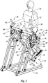
- FIG. 2 is an isometric view of an exercise device which includes drive handles, the figure presented in accordance with the present invention.
- FIG. 3 is an isometric view of the exercise device shown as shown in FIG. 2 , shown without a simulated user and from a right front viewpoint.
- FIG. 4 is an isometric view from the left rear of the exercise device as shown in FIG. 3 .
- FIG. 5 is an isometric view from the right rear of the exercise device as shown in FIG. 3 with a portion of the frame removed to more clearly show detail of the system.
- FIG. 6 is a side view of the exercise device as shown in FIG. 3 , and illustrating a tracing of the movement of the pedals.
- FIG. 7 is a side view of a modified version of the exercise device shown in FIG. 3 , wherein the upper frame may be movably mounted to the base frame, a tracing of the pedal path at this inclined position is shown in contrast to the flat position of the upper frame in FIG. 6 .
- FIG. 8 is an isometric view from the front left of the exercise device shown in FIG. 7 .
- FIG. 9 is an isometric view from the right rear of the exercise device shown in FIG. 7 .
- FIG. 10 is an isometric view from the left front of the exercise device as shown in FIG. 1 but where the rigid crank links have been replaced with movable crank links.
- FIG. 11 is an isometric view from the left rear of the exercise device as shown FIG. 2 , but where the rigid crank links have been replaced with movable crank links.
- FIG. 12 is an isometric view of a movable crank link removed from the rest of the exercise device as shown in FIG. 11 .
- FIG. 13 is a front view of the exercise device as shown in FIG. 11 .
- FIG. 14 is a side view of the exercise device as shown in FIG. 11 illustrating the tracing of the pedal paths of the movable crank links in a neutral position and also as may be seen when the movable crank links are moved by the user.
- FIG. 15 is an isometric view from the left rear of an exercise device produced in accordance with the present invention in which the crank link pin is movably mounted on the pedal arm.
- FIG. 16 is a detailed view of the crank link pin and pedal arm as shown in FIG. 15 , the view cut along the line 16 - 16 in FIG. 15 .
- FIG. 17 is a side view of the exercise device as shown in FIG. 15 including the tracing of the pedals as altered by the movement of the crank link pin on the pedal arm.
- FIG. 18 is an isometric view of an alternative embodiment of the exercise device as shown in FIG. 1 .
- FIG. 19 is a detail cut away of the support frame and transmission of the exercise device of FIG. 18 , cut along line 19 - 19 .
- FIG. 20 is an isometric view of the exercise device of FIG. 18 , shown from a front, side perspective with a portion of the base frame removed.
- FIG. 21 is a side view of the exercise device of FIG. 18 shown in a non-inclined orientation.
- FIG. 22 is a side view of the exercise device of FIG. 21 , shown in an inclined orientation.
- FIG. 23 is an isometric view of a portion of the exercise device of FIG. 22 , shown from a front, side perspective with a section of the base frame removed.
- the exercise device 20 may include a frame 22 , which may include a base frame 24 and a support frame 26 .
- the support frame 26 may be adapted to support a first crank assembly 28 , which may be journaled to the support frame 26 to allow for rotational movement of the first crank assembly 28 about a first axis 30 .
- a second crank assembly 32 may be journaled to the support frame 26 about a second axis 34 .
- the locations of the first axis 30 and the second axis 34 may be positioned to cause a potential interference with a user 36 using the exercise device 20 .
- first crank assembly 28 and the second crank assembly 32 may each be split into a left crankset and a right crankset.
- a drive shaft 42 may also be journaled to the support frame 26 as illustrated.
- first crank assembly 28 and the second crank assembly 32 may move in a synchronous manner with respect to one another. This may be accomplished by the use of a control system 44 .
- the control system 44 may be comprised of a roller chain, a drive belt, a gearing system or any other mechanical transmission elements known in the art.
- the first axis 30 and the second axis 34 may not allow a direct communication between the right and left portions of the first crank assembly 28 or the second crank assembly 32
- the control system 44 may also be in mechanical communication with the driveshaft 42 .
- the driveshaft 42 may be located in position to mechanically span the entire width of the exercise device 20 , the driveshaft 42 with the control system 44 may then act to connect the left and right portions of each of the first crank assembly 28 and the second crank assembly 32 as well as provide for synchronous rotation of the first crank assembly 28 with respect to the second crank assembly 32 .
- a pedal arm 46 may be rotatably coupled to the first crank assembly 28 on a first end 48 of the pedal arm 46 .
- a pedal 52 On a second end 50 of the pedal arm 46 a pedal 52 may be provided, which may be adapted to support the weight of the user 36 .
- a crank link pin 54 may be provided between the first end 48 and the second end 50 of the pedal arm 46 .
- the crank link pin 54 may be pivotally coupled to a crank link 56 and the crank link 56 may also be coupled to the second crank assembly 32 , thereby connecting the pedal arm 46 to the second crank assembly 32 .
- the drive shaft 42 is positioned such that it is not in line with the first axis 30 or the second axis 34 . That is because both the first axis 30 and the second axis 34 may be positioned to potentially interfere with the movement of the user 36 . As such, the drive shaft 42 may be moved to a position that is unlikely to interfere with the movement of the legs of the user 36 . It is possible that the second axis 34 , and the second crank assembly 32 , could be moved far enough forward to avoid the legs of the user 36 . If that were done, the drive shaft 42 could directly connect the second crank assembly 32 .
- crank link 56 may then be increased in length in accordance with the increase in dimension of the relocation of the second axis 34 relative to the current position. This would eliminate the need for some components in the system. The applicant recognizes this could be done and hereby includes this as a variation to the disclosed embodiments even though this is not shown in any of the figures.
- a similar exercise device 20 is shown with the addition of drive handles 58 , which may be pivotally coupled to the frame 22 about a pivot pin 60 .
- the drive handles 58 may each include a hand grip 62 adapted to be gripped by the hands of the user 36 .
- the drive handles 58 may also include a drive lever 64 , which may be coupled to a handle link 66 about a pivot 68 .
- the handle link 66 may include a second pivot 70 , which may be mounted to the first crank assembly 28 at second pivot 70 .
- the user 36 may be positioned on the pedals 52 of the pedal arms 46 and perform a walking motion such that the first crank assembly 28 may provide a vertical displacement of each pedal arm 46 , and therefore the pedal 52 , while the second crank assembly 32 may provide for horizontal displacement of the pedal 52 by way of the crank link 56 .
- This movement may drive the driveshaft 42 , thus causing it to rotate about the bearings 72 , which may be mounted to the support frame 26 of the frame 22 .
- a flywheel 74 may be coupled to the driveshaft 42 , whereby rotation of the driveshaft 42 about the bearings 72 may cause a similar rotation of the flywheel 74 . It may also be desirable to include a braking system to resist the movement of the pedals 52 .
- a braking system may include a friction strap 76 mounted to a screw 78 , which may be mounted to the support frame 26 . Therefore, as the screw 78 is advanced this may increase the tension in the friction strap 76 , which may increase the drag and therefore increase the resistance to movement of the flywheel 74 . This may increase the work necessary to be provided by the user 36 , thus increasing the intensity of the exercise.
- any magnetic form of resistance known to the art such as an electric motor, an eddy current brake or any other braking system may be used in place of the combination of the friction strap 76 and screw 78 .
- the support frame 26 has been removed to better illustrate this embodiment of the present invention 20 .
- the elements as previously shown and described are consistent with that as presented above. What may also be more clearly seen in this figure is the potential use of a tension device to optimize the function of the control system 44 .
- the control system 44 may include a roller chain or drive belt. It may be desirable to use an idler pulley 80 positioned relative to the drive belt or roller chain of the control system 44 so as to displace a portion of the roller chain or drive belt, thus creating proper tension in the drive belt or roller chain to optimize the function of the control system 44 .
- FIG. 6 a side view of the exercise device 20 is shown with a trace of a pedal path 82 .
- the pedal arms 46 may be connected to the first crank assembly 28 .
- the control system 44 may provide the same direction of rotation of the second crank assembly 32 , as designated by the second arrow 86 .
- the second crank assembly 32 may drive the crank link 56 to alter the angular orientation of the pedal arms 46 , as they are driven by the first crank assembly 28 .
- the pedal arm 46 on the left may move generally down and to the right, as shown by the first pedal arrow 88 , while the pedal arm 46 on the right may move generally up and to the right until it changes direction to move to the left and moving down as illustrated by the second pedal arrow 90 .
- An example of a complete path of the pedals 52 may be shown moving along the trace of the pedal path 82 .
- one method to increase the workload in the present exercise device 20 is by providing resistance to rotation of the flywheel 74 by way of the friction strap 76 or any other form of resistance, such as any number of electromagnetic braking systems.
- An alternative may be to increase the angle of the pedal path.
- a solution to do so is illustrated in FIGS. 7-9 .
- the trace of the pedal path 82 may be similar to that of a normal walking gait of a person. This walking gait may be similar to that of a person walking on a treadmill with no incline.
- the user may increase the incline or grade of the treadmill deck.
- a person walking on a flat 0% grade versus walking the same speed at a 10% grade will have an estimated metabolic requirement of over 2.3 times greater walking at the inclined grade. Therefore, changing the angle of incline of the gait pattern of the user may also increase energy expenditure of the user during the exercise session.
- a walking gait may result in significantly lower impact stress on the joints of the user, it may be desirable for a user to exercise in this manner as opposed to running and expend a similar amount of energy per unit of time performing the inclined walking exercise.
- the frame 22 ′ may include the base frame 24 , which may be supported on the ground or floor as with the other embodiments.
- the support frame 26 ′ may include a support frame pivot 92 , which may be coupled to the base frame 24 . This may allow the support frame 26 ′ to change its angular orientation with respect to the base frame 24 by pivoting about the support frame pivot 92 .
- An actuator 94 may be positioned between the base frame 24 and the support frame 26 ′ wherein as the actuator 94 extends, the angle between the support frame 26 ′ and the base frame 24 may be increased. As may be illustrated in FIG.
- the trace of the pedal path 82 may have the same overall shape as that shown in FIG. 6 where the exercise device 20 is at a standard flat position, but the trace of the pedal path 82 may be rotated in FIG. 7 in accordance with the increase in angle of the support frame 26 ′ relative to the base frame 24 . This may allow a user to increase the workload of the exercise session to a varying degree according to the amount of incline the user selects between the support frame 26 ′ and the base frame 24 .
- FIGS. 10-14 An example of how this may be accomplished is shown in FIGS. 10-14 .
- the general function of the exercise device 20 ′′ may be the same as previously shown and described with the exception of the crank link 56 may be replaced with a movable crank link 96 .
- the movable crank arm 96 may include a first link 98 and a second link 100 , which may be pivotally coupled about a crank link pin 102 .
- a first spring 104 may be coupled to the first link 98 and the second link 100 and in a similar but opposite manner, a second spring 106 may likewise be coupled to the first link 98 and the second link 100 .
- the orientation of the first spring 104 and the second spring 106 may apply a balanced couple to the first link 98 relative to the second link 100 so that the distance “x” between the bearing attachments 108 may be biased to a predetermined dimension.
- the movable crank arm 96 may be biased to a dimension “x” between the bearing attachments 108 , if a force is applied to the movable crank arm 96 in a direction to decrease the value of “x”, the first spring 104 may increase in length and the second spring 106 may decrease in length.
- a spring may obey “Hook's Law” in that the force needed to deform a spring by some distance is proportional to that distance. Therefore in this example, if a force is applied to cause the distance “x” to decrease, as depicted by the compression arrows 110 shown in FIG. 12 , the length of the first spring 104 may increase and therefore the force applied by the spring to the first link 98 and the second link 100 would also proportionally increase. The length of the second spring 106 may decrease, and therefore the force applied to the first link 98 and the second link 100 by the second spring 106 may proportionally decrease.
- the first spring 104 may decrease in length (and applied force) and the second spring 106 may increase in length (and applied force).
- the movable crank link 96 may allow for the dimension “x” to be increased or decreased by forces applied to the movable crank link 96 , but the action of the first spring 104 and the second spring 106 may provide a pair of forces that may be balanced optimally when the dimension “x” is at a predetermined value.
- This combination may allow for displacement of the first link 98 relative to the second link 100 of the movable crank link 96 to allow the value of “x” to vary, but yet provide a bias to return the orientation of the movable crank link 96 to that so the dimension “x” may be a predetermined value.
- the force applied to the movable crank links 96 may be applied by the user to the pedals 52 .
- This may be illustrated in more detail in FIG. 14 , where the previously illustrated trace of the pedal path 82 is presented as it may be generated if the movable crank links 96 maintain a set angular orientation of the first link 98 relative to the second link 100 , so as to provide a constant dimension “x”, as shown in FIG. 12 .
- a force may be applied to the movable crank link 96 coupled to the forward pedal arm 46 (left one in FIG.
- the user may apply a force to the rear pedal 52 , (right one in FIG. 14 ) which may cause the movable crank link 96 connected to the pedal arm 46 supporting the rear pedal 52 (right one in FIG. 14 ) to move in the direction of the extension arrows 112 , or to increase the value of dimension “x”.
- This may allow the pedal 52 supporting the rear foot to extend beyond the trace of the pedal path 82 on the rear pedal 52 (right one in FIG. 14 ) to generate a rear pedal path trace extension 116 .
- the combination may provide an increased stride length of the pedals 52 , which may accommodate a taller person, or anyone else that may want a longer stride length. This may be accomplished by the user overcoming the resistance provided by the first spring 104 and the second spring 106 as needed and to the extent desired by the user.
- FIGS. 15-17 Another option to vary the stride length of the pedals 52 is presented in FIGS. 15-17 .
- the crank link 56 may be used, or the movable crank link 96 as disclosed previously.
- the movable crank link 96 may enable a system in which the user may alter the stride length by simply using a longer stride length in their gait and the exercise device 20 ′′ may conform to the user's foot path of travel.
- FIGS. 15-17 a system is illustrated which may provide a set stride length that is adjustable. It is possible to use both the movable crank link 96 as disclosed with the adjustable system illustrated in FIGS. 15-17 . That combination is not shown though it is understood that this combination is inherently part of this disclosure.
- an exercise device 20 ′′′ is shown in which the crank link pin 54 of the previous embodiments may be replaced with a movable link pin 118 .
- the movable link pin 118 may be slidably or pivotally mounted to the pedal arm 46 . It is shown to be received by a slot 120 in the pedal arm 46 , but this slot 120 is not critical.
- the movable link pin 118 may be mounted to the linear slide, or pivotally coupled to the pedal arm 46 , in any way that is known in the art, so that a controlled movement of the movable link pin 118 may be provided.
- An actuator 122 may be used to move the movable link pin 118 on the pedal arm 46 closer to, or further from, the first end 48 of the pedal arm 46 . If the movable link pin 118 is moved up closer to the first end 48 of the pedal arm 46 , as illustrated by the up arrows 124 , the stride length of the pedal 52 may be increased. If the movable link pin 118 is moved down, farther from the first end 48 of the pedal arm 46 , as illustrated by the down arrows 126 , the stride length of the pedal 52 may be decreased.
- This adjustment of the relative position of the movable link pin 118 as moved by the actuator 122 may be adjusted by the user before an exercise session begins or with a system that may be powered, such as with the actuator 122 , the adjustment may be also accomplished while the user is performing the exercise.
- a simple screw adjustment or even a movable but locking movable link pin 118 system may be used where the user may adjust and lock the movable link pin 118 in a set position prior to beginning the exercise session.
- the horizontal displacement of multiple stride lengths of the pedals 52 that may be provided by varying the position of the movable link pin 118 is illustrated in FIG. 17 .
- the trace of the pedal path 82 may be shown as a midpoint of the location of the movable link pin 118 . This may provide a horizontal dimension of the trace of the pedal path 82 as identified by the value “B”. If the movable link pin 118 is moved in accordance with the down arrows 126 , thereby increasing the distance between the movable link pin 118 and the first end 48 of the pedal arm 46 , a shorter pedal path 128 may result. The shorter pedal path 128 may be associated with a smaller horizontal displacement identified as “A”. If the movable link pin 118 is moved closer to the first end 48 of the pedal arms 46 , as noted by the up arrows 124 , a greater stride length may result.
- the longer pedal path 130 may be associated with the greater horizontal displacement identified as “C”.
- the adjustment in the stride length may provide a series of set pedal paths ( 82 , 128 , 130 ) or any infinite number of variations to those shown.
- Each path may be a result of the settings of the exercise device 20 ′′′ and therefore stable to the user, as the user may not be able to alter the pedal paths without making an adjustment to the position of the movable link pin 118 .
- This stability may be desirable to some users in that their body may be fully supported on the pedals 52 of the exercise device 20 ′′′.
- movable crank link 96 with the adjustable stride length system as provided by the movable link pin 118 may provide a system which allows for the user to vary their stride length where the path of the pedals 52 comply with that of the user, and an adjustable baseline path of the path of the pedals 52 may be provided by the movable link pin 118 and set in accordance with the desire or some physical characteristics of the user.
- the support frame 26 ′′ may be comprised of first drive 132 and a second drive 134 , each coupled to the support frame 26 ′′.
- the support frame 26 ′′ may be movably coupled to the base frame 24 by way of a pivot joint 136 .
- the first drive 132 and the second drive 134 may be positioned such that a person may position themselves between the first drive 132 and the second drive 134 .
- the support frame 26 ′′ may also support the drive shaft 42 , which may be in mechanical communication with the flywheel 74 .
- the first drive 132 and the second drive 134 may each support a first crank assembly 28 and a second crank assembly 32 in such a manner such that the first crank arm 38 of the first crank assembly 28 , coupled to the first drive 132 may be one hundred and eighty degrees out of phase from the first crank arm 38 of the first crank assembly 28 , coupled to the second drive 134 .
- the second crank assembly 32 may include a second crank arm 40 coupled to the first drive 132 that may be one hundred and eighty degrees out of phase from the second crank arm 40 , coupled to the second drive 134 .
- the first crank arm 38 and the second crank arm 40 may be parallel to each other on both the first drive 132 and the second drive 134 .
- a drive pulley 135 may be mounted to the drive shaft 42 .
- the drive pulley 135 may be in mechanical communication with the flywheel 74 by way of a drive belt 137 .
- a braking system may be coupled to the flywheel 74 so that resistance provided to the flywheel 74 may offer a resistance to movement of the drive shaft 42 , which in turn may offer a resistance to movement of the pedals 52 . This combination may offer a form of exercise resistance to the user.
- the control system 44 may include a drive member 138 , which may take the form of a belt, roller chain, a synchronous belt, a v-belt, a poly-v belt or any other power transmission system known in the art.
- the drive member 138 as shown here in the form of a belt, may be tensioned by the idler 80 .
- a drive pulley 140 may be secured to the first crank assembly 28 and the second crank assembly 32 on both the first drive 132 and the second drive 134 .
- the drive member 138 may be limited to a belt or other power transmission system alone. Alternatively it may be advantageous to provide a secondary power transmission system in the form of a torque linkage 142 .
- This may include a link rod 144 that may be coupled to the second crank assembly 32 and the drive shaft 42 by way of a pair of clamp links 146 .
- This torque linkage 142 may be used to supplement the drive member 138 when high torque is applied to the second crank assembly 32 by the user.
- the braking system may be applied to the flywheel 74 , as such, the highest load may be seen between the second crank assembly 32 and the drive shaft 42 .
- the use of the torque linkage 142 may allow the drive member 138 to be designed for the lower torque associated with extended use by a user and when high forces are applied by the user, such as during sprinting or high incline “hiking” movements, the torque linkage 142 may supplement the power transmission, taking any excessive stress off the drive member 138 . This may help eliminate the possibility of drive member 138 jumping a tooth of one of the drive pulleys 140 without the need to over engineer the drive member 138 and drive pulleys 140 for stresses that are only seen occasionally and for short durations.
- the torque linkage 142 is shown here to connect the second crank assembly 32 to the drive shaft 42 , which may be connected to the braking system. This combination may experience the highest forces and that is why it is shown in this configuration. It is understood that one or more torque linkages 142 may connect any one or more combinations between the first crank assembly 28 , the second crank assembly 32 and the drive shaft 42 .
- the transfer of the higher forces that may be added by the user to the torque linkage 142 may be generated by the user by positioning the exercise device 20 ′′′′ in a configuration so as to simulate walking up a hill. In this embodiment, this may be accomplished by altering the position of the support frame 26 ′′ and all the elements supported by the support frame 26 ′′ with respect to the base frame 24 . One method of doing this is illustrated in FIGS. 21-23 .
- the support frame 26 ′′ may be pivotally coupled to the base frame 24 about the pivot joint 136 .
- One or more counterbalance springs 148 may be coupled to the support frame 26 ′′ and to the base frame 24 to counter any torque the support frame 26 ′′ may provide at rest about the pivot joint 136 due to the weight of the support frame 26 ′′ and the other elements coupled to the support frame 26 ′′.
- This counterbalance spring 148 may be in the form of a gas spring.
- An actuator such as a linear screw actuator, may be substituted for one or both of the counterbalance springs 148 shown here. In that embodiment, the actuator may drive the front portion of the support frame 26 ′′ up or down and thereby change the angular orientation of the support frame 26 ′′ relative to the base frame 24 . By changing this orientation, the pedal path, as shown in previous figures, may also change, as inclining the front of the support frame 26 ′′ up may cause the pedal path to simulate walking up a hill.
- the gas springs may be used as the counterbalance springs 148 with an incline adjustment 150 .
- the incline adjustment 150 may include a first support 152 , which may articulate with a second support 154 , and a locking pin 156 to releasably secure the first support 152 to the second support 154 at desired positions. This may securely alter the dimension between a support frame pin 158 and a base frame pin 160 .
- exercise device 20 ′′′′ may produce an inclined pedal angle from flat (as shown in FIG. 21 ) to an inclined position (as shown in FIG. 22 ).
- the user may disengage the locking pin 156 , move the support frame 26 ′′ to a desired position, being aided by the counterbalance springs 148 , and then engaging the locking pin 158 to secure the support frame 26 ′′ and therefore the first drive 132 and the second drive 134 , to a desired level of incline.
- the drive handles 58 of previous embodiments have been removed and a set of stationary leaning handles 162 are shown. These handle types are not mutually exclusive to any embodiment.
- the leaning handles 162 may be desirable in some angular orientations of the exercise device 20 and the moving drive handles 58 may be desirable in other orientations, or as a personal preference in any orientation.
- Either form of handles (moving drive handles 58 or stationary leaning handles 162 ) may be interchangeably used or in combination together on any embodiment.
- a method of altering the pedal path by varying the position of the crank link 56 on the pedal arm 46 has been disclosed.
- This embodiment of the exercise device 20 ′′ illustrates a manually adjustable version to accomplish this task.
- An adjustment bracket 164 may be releasably secured to the pedal arm 46 at one or more positions on the pedal arm 46 .
- a leg lock pin 166 may be used to releasably secure the adjustment bracket 164 to a position on the pedal arm 46 .
- the crank link 56 may be pivotally secured to the adjustment bracket 164 at the movable lock pin 118 , and as noted before, also to the second crank arm 40 . Therefore, by adjusting and securing the adjustment bracket 164 at different positions on the pedal arm 46 , the path of the pedals 52 may be altered to achieve more than one pedal path, as previously disclosed.
Abstract
Description
Claims (15)
Priority Applications (7)
| Application Number | Priority Date | Filing Date | Title |
|---|---|---|---|
| US15/609,910 US11123598B2 (en) | 2016-07-05 | 2017-05-31 | Exercise device |
| PCT/US2017/039900 WO2018009403A1 (en) | 2016-07-05 | 2017-06-29 | Exercise device |
| CN201780053668.4A CN109689170B (en) | 2016-07-05 | 2017-06-29 | Exercise device |
| TW106122378A TWI637767B (en) | 2016-07-05 | 2017-07-04 | Exercise device |
| US17/405,347 US11623117B2 (en) | 2016-07-05 | 2021-08-18 | Exercise device |
| US18/299,017 US20230310926A1 (en) | 2016-07-05 | 2023-04-11 | Exercise device |
| US18/352,241 US20240017121A1 (en) | 2016-07-05 | 2023-07-14 | Exercise device with drive handles |
Applications Claiming Priority (2)
| Application Number | Priority Date | Filing Date | Title |
|---|---|---|---|
| US201662358517P | 2016-07-05 | 2016-07-05 | |
| US15/609,910 US11123598B2 (en) | 2016-07-05 | 2017-05-31 | Exercise device |
Related Child Applications (2)
| Application Number | Title | Priority Date | Filing Date |
|---|---|---|---|
| US17/405,347 Division US11623117B2 (en) | 2016-07-05 | 2021-08-18 | Exercise device |
| US17/405,347 Continuation US11623117B2 (en) | 2016-07-05 | 2021-08-18 | Exercise device |
Publications (2)
| Publication Number | Publication Date |
|---|---|
| US20180008861A1 US20180008861A1 (en) | 2018-01-11 |
| US11123598B2 true US11123598B2 (en) | 2021-09-21 |
Family
ID=60892954
Family Applications (4)
| Application Number | Title | Priority Date | Filing Date |
|---|---|---|---|
| US15/609,910 Active 2038-03-21 US11123598B2 (en) | 2016-07-05 | 2017-05-31 | Exercise device |
| US17/405,347 Active 2037-07-25 US11623117B2 (en) | 2016-07-05 | 2021-08-18 | Exercise device |
| US18/299,017 Pending US20230310926A1 (en) | 2016-07-05 | 2023-04-11 | Exercise device |
| US18/352,241 Pending US20240017121A1 (en) | 2016-07-05 | 2023-07-14 | Exercise device with drive handles |
Family Applications After (3)
| Application Number | Title | Priority Date | Filing Date |
|---|---|---|---|
| US17/405,347 Active 2037-07-25 US11623117B2 (en) | 2016-07-05 | 2021-08-18 | Exercise device |
| US18/299,017 Pending US20230310926A1 (en) | 2016-07-05 | 2023-04-11 | Exercise device |
| US18/352,241 Pending US20240017121A1 (en) | 2016-07-05 | 2023-07-14 | Exercise device with drive handles |
Country Status (4)
| Country | Link |
|---|---|
| US (4) | US11123598B2 (en) |
| CN (1) | CN109689170B (en) |
| TW (1) | TWI637767B (en) |
| WO (1) | WO2018009403A1 (en) |
Families Citing this family (3)
| Publication number | Priority date | Publication date | Assignee | Title |
|---|---|---|---|---|
| US11801419B2 (en) * | 2019-05-23 | 2023-10-31 | Rehab2Fit Technologies, Inc. | System, method and apparatus for rehabilitation and exercise with multi-configurable accessories |
| US11123599B2 (en) * | 2019-06-14 | 2021-09-21 | Kenn Hundley | Running emulator |
| TWM608371U (en) * | 2020-09-10 | 2021-03-01 | 敦洋科技股份有限公司 | Reciprocating transmission structure of fitness equipment |
Citations (65)
| Publication number | Priority date | Publication date | Assignee | Title |
|---|---|---|---|---|
| US219439A (en) | 1879-09-09 | Improvement in passive-motion walking-machines | ||
| US2872191A (en) | 1956-12-28 | 1959-02-03 | Sr John Gallo | Amusement and exercising device |
| US3758111A (en) | 1971-05-03 | 1973-09-11 | A Agamian | Situ apparatus for physical exercise with pedal action |
| US3759511A (en) | 1971-03-29 | 1973-09-18 | K Gustafson | Adjustable friction type exercising device |
| US3820820A (en) | 1972-04-03 | 1974-06-28 | J Kutz | Pedal drive |
| US4185622A (en) | 1979-03-21 | 1980-01-29 | Swenson Oscar J | Foot and leg exerciser |
| US4188030A (en) | 1976-10-18 | 1980-02-12 | Repco Limited | Cycle exerciser |
| US4470597A (en) | 1982-04-20 | 1984-09-11 | Mcfee Richard | Exerciser with flywheel |
| US4564206A (en) | 1983-10-11 | 1986-01-14 | Lenhardt Larry G | Pedal drive |
| US4712790A (en) | 1987-04-20 | 1987-12-15 | Schwinn Bicycle Company | Cycle exerciser |
| US4779863A (en) | 1987-06-26 | 1988-10-25 | Yang Kuey M | Running exercise bicycle |
| US4786050A (en) | 1986-11-06 | 1988-11-22 | Geschwender Robert C | Exercise machine |
| US4850585A (en) | 1987-09-08 | 1989-07-25 | Weslo, Inc. | Striding exerciser |
| US5135447A (en) | 1988-10-21 | 1992-08-04 | Life Fitness | Exercise apparatus for simulating stair climbing |
| US5290211A (en) | 1992-10-29 | 1994-03-01 | Stearns Technologies, Inc. | Exercise device |
| US5433680A (en) | 1994-07-05 | 1995-07-18 | Knudsen; Paul D. | Elliptical path pedaling system |
| US5527246A (en) | 1995-01-25 | 1996-06-18 | Rodgers, Jr.; Robert E. | Mobile exercise apparatus |
| US5529555A (en) | 1995-06-06 | 1996-06-25 | Ccs, Llc | Crank assembly for an exercising device |
| US5540637A (en) | 1995-01-25 | 1996-07-30 | Ccs, Llc | Stationary exercise apparatus having a preferred foot platform orientation |
| US5549526A (en) | 1995-01-25 | 1996-08-27 | Ccs, Llc | Stationary exercise apparatus |
| US5573480A (en) | 1995-01-25 | 1996-11-12 | Ccs, Llc | Stationary exercise apparatus |
| US5577985A (en) | 1996-02-08 | 1996-11-26 | Miller; Larry | Stationary exercise device |
| US5591107A (en) | 1995-01-25 | 1997-01-07 | Rodgers, Jr.; Robert E. | Mobile exercise apparatus |
| US5707321A (en) | 1995-06-30 | 1998-01-13 | Maresh; Joseph Douglas | Four bar exercise machine |
| US5725457A (en) | 1995-09-28 | 1998-03-10 | Maresh; Joseph Douglas | Six bar exercise machine |
| US5792028A (en) | 1997-08-15 | 1998-08-11 | Jarvie; John E. | Running exercise machine |
| US5800315A (en) | 1997-10-30 | 1998-09-01 | Yu; Hui-Nan | Oval track exercising climber |
| US5876308A (en) * | 1998-06-26 | 1999-03-02 | Jarvie; John E. | Running exercise machine |
| US5876307A (en) * | 1997-04-04 | 1999-03-02 | Stearns; Kenneth W. | Elliptical motion exercise apparatus |
| US5910072A (en) * | 1997-12-03 | 1999-06-08 | Stairmaster Sports/Medical Products, Inc. | Exercise apparatus |
| US6004244A (en) | 1997-02-13 | 1999-12-21 | Cybex International, Inc. | Simulated hill-climbing exercise apparatus and method of exercising |
| US6248044B1 (en) | 1997-08-19 | 2001-06-19 | Kenneth W. Stearns | Elliptical exercise methods and apparatus |
| US6398695B2 (en) | 1998-09-24 | 2002-06-04 | Larry Miller | Elliptical exercise device |
| US6409632B1 (en) | 1996-09-09 | 2002-06-25 | Paul William Eschenbach | Compact elliptical exercise machine |
| US20020123412A1 (en) | 2001-03-01 | 2002-09-05 | Nguyen Hieu Trong | Multi-function exercise apparatus |
| US6461277B2 (en) | 1997-04-26 | 2002-10-08 | Joseph D. Maresh | Exercise methods and apparatus |
| US6482132B2 (en) | 1996-09-09 | 2002-11-19 | Paul William Eschenbach | Compact elliptical exercise apparatus |
| US6551218B2 (en) | 1999-04-26 | 2003-04-22 | Unisen, Inc. | Deep stride exercise machine |
| US20050124466A1 (en) * | 2003-12-04 | 2005-06-09 | Rodgers Robert E.Jr. | Pendulum striding exercise apparatus |
| US6949054B1 (en) | 2003-06-26 | 2005-09-27 | Stearns Kenneth W | Exercise methods and apparatus with elliptical foot motion |
| US7060005B2 (en) | 2004-01-05 | 2006-06-13 | Diamondback Fitness, Inc. | Exercise device |
| US7086993B1 (en) | 1995-06-30 | 2006-08-08 | Maresh Joseph D | Exercise methods and apparatus |
| US7169089B2 (en) | 2003-06-06 | 2007-01-30 | Rodgers Jr Robert E | Compact variable path exercise apparatus with a relatively long cam surface |
| US7285075B2 (en) | 2003-12-11 | 2007-10-23 | Icon Ip, Inc. | Incline trainer |
| US20080051258A1 (en) * | 2006-08-22 | 2008-02-28 | Jacob Stewart Schmehl | Elliptical exercise device and methods of use |
| US20080261778A1 (en) | 2007-04-17 | 2008-10-23 | Jin Chen Chuang | Adjusting exercise device |
| US20080269023A1 (en) * | 2007-04-30 | 2008-10-30 | Jin Chen Chuang | Stationary exercise device |
| EP2000178A1 (en) | 2007-06-06 | 2008-12-10 | Jin Chen Chuang | Stationary exercise device |
| US7485080B1 (en) | 2007-09-18 | 2009-02-03 | Jin Chen Chuang | Stationary exerciser |
| US7530926B2 (en) | 2003-12-04 | 2009-05-12 | Rodgers Jr Robert E | Pendulum striding exercise devices |
| US7556691B2 (en) | 2005-02-15 | 2009-07-07 | Crayola Llc | Spin art apparatus |
| US20090247371A1 (en) * | 2004-07-30 | 2009-10-01 | Unisen, Inc., Dba Star Trac | Linkage based exercise machine |
| US7611446B2 (en) * | 2007-04-17 | 2009-11-03 | Jin Chen Chuang | Adjustable exercise device |
| US7645215B2 (en) | 2005-08-11 | 2010-01-12 | Gordon Joel D | Exercise device |
| US7651445B1 (en) | 2008-10-08 | 2010-01-26 | I-Huang Chen | Elliptical trainer |
| US7862482B1 (en) | 2009-11-12 | 2011-01-04 | Kuan-Yung Hsu | Adjustable elliptical trainer |
| US20110039662A1 (en) * | 2006-08-10 | 2011-02-17 | Exerciting, Llc | Exercise device with varied gait movements |
| US20120289380A1 (en) | 2011-05-12 | 2012-11-15 | Chao-Chuan Chen | Multi-mode exercise bike |
| US20140141939A1 (en) * | 2012-11-21 | 2014-05-22 | Strength Master Fitness Tech Co., Ltd. | Treading exerciser and method for controlling resistance of the treading exerciser |
| US8740754B2 (en) * | 2010-01-11 | 2014-06-03 | Larry D. Miller | Adaptive exercise device |
| US20140249000A1 (en) * | 2013-03-04 | 2014-09-04 | Brunswick Corporation | Exercise Assemblies Having Crank Members with Limited Rotation |
| US9073597B2 (en) | 2013-10-25 | 2015-07-07 | Mauro Rundini | Crank systems and methods |
| US9630052B2 (en) | 2015-07-17 | 2017-04-25 | Mario Contenti Designs Co., Ltd. | Elliptic-orbit treadmill |
| US9925412B1 (en) * | 2016-02-01 | 2018-03-27 | Brunswick Corporation | Linkage assemblies for exercise devices |
| US10046197B2 (en) * | 2015-11-19 | 2018-08-14 | Fitnovation, Inc. | Exercise device |
Family Cites Families (6)
| Publication number | Priority date | Publication date | Assignee | Title |
|---|---|---|---|---|
| US6196948B1 (en) * | 1998-05-05 | 2001-03-06 | Kenneth W. Stearns | Elliptical exercise methods and apparatus |
| CN201006233Y (en) * | 2007-02-07 | 2008-01-16 | 翰威实业股份有限公司 | Setover adjustable treadle and walk dual-purpose body builder |
| TWI332410B (en) * | 2007-06-06 | 2010-11-01 | Jin Chen Chuang | Freely style exercise device |
| US8864631B1 (en) * | 2008-02-19 | 2014-10-21 | Kenneth W Stearns | Exercise methods and apparatus |
| CN201333285Y (en) * | 2008-10-31 | 2009-10-28 | 力伽实业股份有限公司 | Exercise machine |
| US7922625B2 (en) * | 2008-12-29 | 2011-04-12 | Precor Incorporated | Adaptive motion exercise device with oscillating track |
-
2017
- 2017-05-31 US US15/609,910 patent/US11123598B2/en active Active
- 2017-06-29 WO PCT/US2017/039900 patent/WO2018009403A1/en active Application Filing
- 2017-06-29 CN CN201780053668.4A patent/CN109689170B/en active Active
- 2017-07-04 TW TW106122378A patent/TWI637767B/en active
-
2021
- 2021-08-18 US US17/405,347 patent/US11623117B2/en active Active
-
2023
- 2023-04-11 US US18/299,017 patent/US20230310926A1/en active Pending
- 2023-07-14 US US18/352,241 patent/US20240017121A1/en active Pending
Patent Citations (77)
| Publication number | Priority date | Publication date | Assignee | Title |
|---|---|---|---|---|
| US219439A (en) | 1879-09-09 | Improvement in passive-motion walking-machines | ||
| US2872191A (en) | 1956-12-28 | 1959-02-03 | Sr John Gallo | Amusement and exercising device |
| US3759511A (en) | 1971-03-29 | 1973-09-18 | K Gustafson | Adjustable friction type exercising device |
| US3758111A (en) | 1971-05-03 | 1973-09-11 | A Agamian | Situ apparatus for physical exercise with pedal action |
| US3820820A (en) | 1972-04-03 | 1974-06-28 | J Kutz | Pedal drive |
| US4188030A (en) | 1976-10-18 | 1980-02-12 | Repco Limited | Cycle exerciser |
| US4185622A (en) | 1979-03-21 | 1980-01-29 | Swenson Oscar J | Foot and leg exerciser |
| US4470597A (en) | 1982-04-20 | 1984-09-11 | Mcfee Richard | Exerciser with flywheel |
| US4564206A (en) | 1983-10-11 | 1986-01-14 | Lenhardt Larry G | Pedal drive |
| US4786050A (en) | 1986-11-06 | 1988-11-22 | Geschwender Robert C | Exercise machine |
| US4712790A (en) | 1987-04-20 | 1987-12-15 | Schwinn Bicycle Company | Cycle exerciser |
| US4779863A (en) | 1987-06-26 | 1988-10-25 | Yang Kuey M | Running exercise bicycle |
| US4850585A (en) | 1987-09-08 | 1989-07-25 | Weslo, Inc. | Striding exerciser |
| US5135447A (en) | 1988-10-21 | 1992-08-04 | Life Fitness | Exercise apparatus for simulating stair climbing |
| US5290211A (en) | 1992-10-29 | 1994-03-01 | Stearns Technologies, Inc. | Exercise device |
| US5401226A (en) | 1992-10-29 | 1995-03-28 | Stearns Technologies, Inc. | Exercise device |
| US5433680A (en) | 1994-07-05 | 1995-07-18 | Knudsen; Paul D. | Elliptical path pedaling system |
| US5527246A (en) | 1995-01-25 | 1996-06-18 | Rodgers, Jr.; Robert E. | Mobile exercise apparatus |
| US5591107A (en) | 1995-01-25 | 1997-01-07 | Rodgers, Jr.; Robert E. | Mobile exercise apparatus |
| US5540637A (en) | 1995-01-25 | 1996-07-30 | Ccs, Llc | Stationary exercise apparatus having a preferred foot platform orientation |
| US5549526A (en) | 1995-01-25 | 1996-08-27 | Ccs, Llc | Stationary exercise apparatus |
| US5573480A (en) | 1995-01-25 | 1996-11-12 | Ccs, Llc | Stationary exercise apparatus |
| US5637058A (en) | 1995-01-25 | 1997-06-10 | Ccs, L.L.C. | Stationary exercise apparatus |
| US5529555A (en) | 1995-06-06 | 1996-06-25 | Ccs, Llc | Crank assembly for an exercising device |
| US5707321A (en) | 1995-06-30 | 1998-01-13 | Maresh; Joseph Douglas | Four bar exercise machine |
| US7344480B2 (en) | 1995-06-30 | 2008-03-18 | Maresh Joseph D | Exercise methods and apparatus |
| US7137927B2 (en) | 1995-06-30 | 2006-11-21 | Maresh Joseph D | Exercise methods and apparatus |
| US7086993B1 (en) | 1995-06-30 | 2006-08-08 | Maresh Joseph D | Exercise methods and apparatus |
| US5897463A (en) | 1995-06-30 | 1999-04-27 | Maresh; Joseph D. | Four bar exercise machine |
| US5725457A (en) | 1995-09-28 | 1998-03-10 | Maresh; Joseph Douglas | Six bar exercise machine |
| US6083143A (en) | 1995-09-28 | 2000-07-04 | Maresh; Joseph D. | Six bar exercise machine |
| US5577985A (en) | 1996-02-08 | 1996-11-26 | Miller; Larry | Stationary exercise device |
| US6482132B2 (en) | 1996-09-09 | 2002-11-19 | Paul William Eschenbach | Compact elliptical exercise apparatus |
| US6409632B1 (en) | 1996-09-09 | 2002-06-25 | Paul William Eschenbach | Compact elliptical exercise machine |
| US6004244A (en) | 1997-02-13 | 1999-12-21 | Cybex International, Inc. | Simulated hill-climbing exercise apparatus and method of exercising |
| US5876307A (en) * | 1997-04-04 | 1999-03-02 | Stearns; Kenneth W. | Elliptical motion exercise apparatus |
| US6461277B2 (en) | 1997-04-26 | 2002-10-08 | Joseph D. Maresh | Exercise methods and apparatus |
| US5792028A (en) | 1997-08-15 | 1998-08-11 | Jarvie; John E. | Running exercise machine |
| US6248044B1 (en) | 1997-08-19 | 2001-06-19 | Kenneth W. Stearns | Elliptical exercise methods and apparatus |
| US5800315A (en) | 1997-10-30 | 1998-09-01 | Yu; Hui-Nan | Oval track exercising climber |
| US5910072A (en) * | 1997-12-03 | 1999-06-08 | Stairmaster Sports/Medical Products, Inc. | Exercise apparatus |
| US5876308A (en) * | 1998-06-26 | 1999-03-02 | Jarvie; John E. | Running exercise machine |
| US6398695B2 (en) | 1998-09-24 | 2002-06-04 | Larry Miller | Elliptical exercise device |
| US6551218B2 (en) | 1999-04-26 | 2003-04-22 | Unisen, Inc. | Deep stride exercise machine |
| US20020123412A1 (en) | 2001-03-01 | 2002-09-05 | Nguyen Hieu Trong | Multi-function exercise apparatus |
| US6761665B2 (en) * | 2001-03-01 | 2004-07-13 | Hieu Trong Nguyen | Multi-function exercise apparatus |
| US7169089B2 (en) | 2003-06-06 | 2007-01-30 | Rodgers Jr Robert E | Compact variable path exercise apparatus with a relatively long cam surface |
| US6949054B1 (en) | 2003-06-26 | 2005-09-27 | Stearns Kenneth W | Exercise methods and apparatus with elliptical foot motion |
| US7530926B2 (en) | 2003-12-04 | 2009-05-12 | Rodgers Jr Robert E | Pendulum striding exercise devices |
| US7708669B2 (en) | 2003-12-04 | 2010-05-04 | Rodgers Jr Robert E | Pendulum striding exercise apparatus |
| US7520839B2 (en) | 2003-12-04 | 2009-04-21 | Rodgers Jr Robert E | Pendulum striding exercise apparatus |
| US20050124466A1 (en) * | 2003-12-04 | 2005-06-09 | Rodgers Robert E.Jr. | Pendulum striding exercise apparatus |
| US7285075B2 (en) | 2003-12-11 | 2007-10-23 | Icon Ip, Inc. | Incline trainer |
| US7060005B2 (en) | 2004-01-05 | 2006-06-13 | Diamondback Fitness, Inc. | Exercise device |
| US20090247371A1 (en) * | 2004-07-30 | 2009-10-01 | Unisen, Inc., Dba Star Trac | Linkage based exercise machine |
| US7556691B2 (en) | 2005-02-15 | 2009-07-07 | Crayola Llc | Spin art apparatus |
| US7833134B2 (en) | 2005-08-11 | 2010-11-16 | Gordon Joel D | Exercise device |
| US7645215B2 (en) | 2005-08-11 | 2010-01-12 | Gordon Joel D | Exercise device |
| US20110039662A1 (en) * | 2006-08-10 | 2011-02-17 | Exerciting, Llc | Exercise device with varied gait movements |
| US8109861B2 (en) | 2006-08-10 | 2012-02-07 | Exerciting, Llc | Exercise device with varied gait movements |
| US20080051258A1 (en) * | 2006-08-22 | 2008-02-28 | Jacob Stewart Schmehl | Elliptical exercise device and methods of use |
| US7611446B2 (en) * | 2007-04-17 | 2009-11-03 | Jin Chen Chuang | Adjustable exercise device |
| US20080261778A1 (en) | 2007-04-17 | 2008-10-23 | Jin Chen Chuang | Adjusting exercise device |
| US7608018B2 (en) | 2007-04-30 | 2009-10-27 | Jin Chen Chuang | Stationary exercise device |
| US20080269023A1 (en) * | 2007-04-30 | 2008-10-30 | Jin Chen Chuang | Stationary exercise device |
| EP2000178A1 (en) | 2007-06-06 | 2008-12-10 | Jin Chen Chuang | Stationary exercise device |
| US7485080B1 (en) | 2007-09-18 | 2009-02-03 | Jin Chen Chuang | Stationary exerciser |
| US7651445B1 (en) | 2008-10-08 | 2010-01-26 | I-Huang Chen | Elliptical trainer |
| US7862482B1 (en) | 2009-11-12 | 2011-01-04 | Kuan-Yung Hsu | Adjustable elliptical trainer |
| US8740754B2 (en) * | 2010-01-11 | 2014-06-03 | Larry D. Miller | Adaptive exercise device |
| US20120289380A1 (en) | 2011-05-12 | 2012-11-15 | Chao-Chuan Chen | Multi-mode exercise bike |
| US20140141939A1 (en) * | 2012-11-21 | 2014-05-22 | Strength Master Fitness Tech Co., Ltd. | Treading exerciser and method for controlling resistance of the treading exerciser |
| US20140249000A1 (en) * | 2013-03-04 | 2014-09-04 | Brunswick Corporation | Exercise Assemblies Having Crank Members with Limited Rotation |
| US9073597B2 (en) | 2013-10-25 | 2015-07-07 | Mauro Rundini | Crank systems and methods |
| US9630052B2 (en) | 2015-07-17 | 2017-04-25 | Mario Contenti Designs Co., Ltd. | Elliptic-orbit treadmill |
| US10046197B2 (en) * | 2015-11-19 | 2018-08-14 | Fitnovation, Inc. | Exercise device |
| US9925412B1 (en) * | 2016-02-01 | 2018-03-27 | Brunswick Corporation | Linkage assemblies for exercise devices |
Also Published As
| Publication number | Publication date |
|---|---|
| TWI637767B (en) | 2018-10-11 |
| CN109689170A (en) | 2019-04-26 |
| US20180008861A1 (en) | 2018-01-11 |
| TW201806647A (en) | 2018-03-01 |
| WO2018009403A1 (en) | 2018-01-11 |
| US20240017121A1 (en) | 2024-01-18 |
| US20210370128A1 (en) | 2021-12-02 |
| CN109689170B (en) | 2021-05-25 |
| US11623117B2 (en) | 2023-04-11 |
| US20230310926A1 (en) | 2023-10-05 |
Similar Documents
| Publication | Publication Date | Title |
|---|---|---|
| US11623117B2 (en) | Exercise device | |
| US10549147B2 (en) | Exercise device providing user defined pedal movements | |
| US7278955B2 (en) | Exercise device for cross training | |
| US7494447B2 (en) | Elliptical exercise apparatus with adjustable crank | |
| US11191995B2 (en) | Pedal assembly for exercise machine | |
| US6811517B1 (en) | Polestrider exercise apparatus with dual treads | |
| US7918766B2 (en) | Elliptical mechanism | |
| US5910072A (en) | Exercise apparatus |
Legal Events
| Date | Code | Title | Description |
|---|---|---|---|
| AS | Assignment |
Owner name: ABELBECK PARTNERS, LTD., COLORADO Free format text: ASSIGNMENT OF ASSIGNORS INTEREST;ASSIGNOR:ABELBECK, KEVIN GENE;REEL/FRAME:042547/0911 Effective date: 20170530 |
|
| AS | Assignment |
Owner name: ABELBECK PARTNERS, LLC, COLORADO Free format text: ASSIGNMENT OF ASSIGNORS INTEREST;ASSIGNOR:ABELBECK, KEVIN G;REEL/FRAME:046274/0238 Effective date: 20180705 |
|
| STPP | Information on status: patent application and granting procedure in general |
Free format text: NON FINAL ACTION MAILED |
|
| STPP | Information on status: patent application and granting procedure in general |
Free format text: RESPONSE TO NON-FINAL OFFICE ACTION ENTERED AND FORWARDED TO EXAMINER |
|
| STPP | Information on status: patent application and granting procedure in general |
Free format text: FINAL REJECTION MAILED |
|
| STPP | Information on status: patent application and granting procedure in general |
Free format text: DOCKETED NEW CASE - READY FOR EXAMINATION |
|
| STPP | Information on status: patent application and granting procedure in general |
Free format text: DOCKETED NEW CASE - READY FOR EXAMINATION |
|
| STPP | Information on status: patent application and granting procedure in general |
Free format text: NOTICE OF ALLOWANCE MAILED -- APPLICATION RECEIVED IN OFFICE OF PUBLICATIONS |
|
| STPP | Information on status: patent application and granting procedure in general |
Free format text: PUBLICATIONS -- ISSUE FEE PAYMENT VERIFIED |
|
| STCF | Information on status: patent grant |
Free format text: PATENTED CASE |