US11120624B2 - Three-dimensional head portrait generating method and electronic device - Google Patents
Three-dimensional head portrait generating method and electronic device Download PDFInfo
- Publication number
- US11120624B2 US11120624B2 US16/414,974 US201916414974A US11120624B2 US 11120624 B2 US11120624 B2 US 11120624B2 US 201916414974 A US201916414974 A US 201916414974A US 11120624 B2 US11120624 B2 US 11120624B2
- Authority
- US
- United States
- Prior art keywords
- texture
- deformed
- grids
- grid images
- grid
- Prior art date
- Legal status (The legal status is an assumption and is not a legal conclusion. Google has not performed a legal analysis and makes no representation as to the accuracy of the status listed.)
- Active
Links
Images


Classifications
-
- G—PHYSICS
- G06—COMPUTING; CALCULATING OR COUNTING
- G06T—IMAGE DATA PROCESSING OR GENERATION, IN GENERAL
- G06T17/00—Three dimensional [3D] modelling, e.g. data description of 3D objects
- G06T17/20—Finite element generation, e.g. wire-frame surface description, tesselation
-
- G—PHYSICS
- G06—COMPUTING; CALCULATING OR COUNTING
- G06T—IMAGE DATA PROCESSING OR GENERATION, IN GENERAL
- G06T15/00—3D [Three Dimensional] image rendering
- G06T15/04—Texture mapping
-
- G—PHYSICS
- G06—COMPUTING; CALCULATING OR COUNTING
- G06T—IMAGE DATA PROCESSING OR GENERATION, IN GENERAL
- G06T17/00—Three dimensional [3D] modelling, e.g. data description of 3D objects
-
- G—PHYSICS
- G06—COMPUTING; CALCULATING OR COUNTING
- G06T—IMAGE DATA PROCESSING OR GENERATION, IN GENERAL
- G06T7/00—Image analysis
- G06T7/40—Analysis of texture
- G06T7/49—Analysis of texture based on structural texture description, e.g. using primitives or placement rules
-
- G—PHYSICS
- G06—COMPUTING; CALCULATING OR COUNTING
- G06T—IMAGE DATA PROCESSING OR GENERATION, IN GENERAL
- G06T7/00—Image analysis
- G06T7/50—Depth or shape recovery
- G06T7/521—Depth or shape recovery from laser ranging, e.g. using interferometry; from the projection of structured light
-
- G—PHYSICS
- G06—COMPUTING; CALCULATING OR COUNTING
- G06V—IMAGE OR VIDEO RECOGNITION OR UNDERSTANDING
- G06V20/00—Scenes; Scene-specific elements
- G06V20/60—Type of objects
- G06V20/64—Three-dimensional objects
- G06V20/653—Three-dimensional objects by matching three-dimensional models, e.g. conformal mapping of Riemann surfaces
-
- G—PHYSICS
- G06—COMPUTING; CALCULATING OR COUNTING
- G06V—IMAGE OR VIDEO RECOGNITION OR UNDERSTANDING
- G06V40/00—Recognition of biometric, human-related or animal-related patterns in image or video data
- G06V40/10—Human or animal bodies, e.g. vehicle occupants or pedestrians; Body parts, e.g. hands
- G06V40/16—Human faces, e.g. facial parts, sketches or expressions
- G06V40/168—Feature extraction; Face representation
-
- G—PHYSICS
- G06—COMPUTING; CALCULATING OR COUNTING
- G06T—IMAGE DATA PROCESSING OR GENERATION, IN GENERAL
- G06T2200/00—Indexing scheme for image data processing or generation, in general
- G06T2200/08—Indexing scheme for image data processing or generation, in general involving all processing steps from image acquisition to 3D model generation
-
- G—PHYSICS
- G06—COMPUTING; CALCULATING OR COUNTING
- G06T—IMAGE DATA PROCESSING OR GENERATION, IN GENERAL
- G06T2207/00—Indexing scheme for image analysis or image enhancement
- G06T2207/30—Subject of image; Context of image processing
- G06T2207/30196—Human being; Person
- G06T2207/30201—Face
Definitions
- the invention relates to a three-dimensional imaging technology and, more particularly, to a three-dimensional head portrait generating method and an electronic device.
- a head portrait is a graph representative of the identity of a user.
- head portraits were mostly flat photos, and a user could not create a virtual self to jump on a screen.
- an image construction technology has gradually developed into a three-dimensional imaging technology from an original two-dimensional imaging technology to meet visual needs of people.
- a scanning instrument first scans the user's face.
- traditional scanning bases are relatively large, or require assistance from others to stably move the scanning instrument to complete scanning, and thus it takes a lot of time to complete scanning.
- general three-dimensional head portraits use pre-established head portrait models, and users cannot establish their own head portrait models.
- a three-dimensional head portrait generating method applied to an electronic device comprises: establishing a three-dimensional head portrait model with a plurality of feature points according to front face information, wherein the feature points form a plurality of first grids on the three-dimensional head portrait model; mapping a first part of the feature points of the three-dimensional head portrait model to a left face image to form a plurality of second grids on the left face image; mapping a second part of the feature points of the three-dimensional head portrait model to a right face image to form a plurality of third grids on the right face image; and superimposing the left face image and the right face image onto the three-dimensional head portrait model according to a correspondence among the first grids, the second grids and the third grids, to generate a three-dimensional head portrait.
- an electronic device includes: an image capture unit, capturing a left face image and a right face image; and a processing unit, establishing a three-dimensional head portrait model with a plurality of feature points according to front face information, wherein the feature points form a plurality of first grids on the three-dimensional head portrait model, the processing unit maps a first part of the feature points of the three-dimensional head portrait model to the left face image to form a plurality of second grids on the left face image, the processing unit maps a second part of the feature points of the three-dimensional head portrait model to the right face image to form a plurality of third grids on the right face image, and the processing unit combines the left face image and the right face image onto the three-dimensional head portrait model according to a correspondence between the first grids, the second grids and the third grids, to generate a three-dimensional head portrait.
- a non-transitory computer readable storage medium storing a plurality of program codes.
- the electronic device When the program codes are loaded on an electronic device, the electronic device performs the following steps: establishing a three-dimensional head portrait model with a plurality of feature points according to front face information, wherein the feature points form a plurality of first grids on the three-dimensional head portrait model; mapping a first part of the feature points of the three-dimensional head portrait model to a left face image to form a plurality of second grids on the left face image; mapping a second part of the feature points of the three-dimensional head portrait model to a right face image to form a plurality of third grids on the right face image; and superimposing the left face image and the right face image onto the three-dimensional head portrait model according to a correspondence among the first grids, the second grids and the third grids, to generate a three-dimensional head portrait.
- FIG. 1 is a schematic overview of an embodiment where a user uses an electronic device
- FIG. 2 is a schematic block overview of an embodiment of an electronic device
- FIG. 3 is a flowchart of an embodiment of a three-dimensional head portrait generating method
- FIG. 4 is a schematic overview of an embodiment of a three-dimensional head portrait model
- FIG. 5 is a schematic overview of an embodiment of a left face image
- FIG. 6 is a schematic overview of an embodiment of a right face image
- FIG. 7 is a schematic overview of an embodiment where a user's face faces an electronic device directly;
- FIG. 8 is a schematic overview of an embodiment where a user's face is right-biased to an electronic device
- FIG. 9 is a schematic overview of an embodiment where a user's face is left-biased to an electronic device
- FIG. 10 is a flowchart of an embodiment of step S 50 in FIG. 3 ;
- FIG. 11 is a flowchart of an embodiment of step S 55 in FIG. 10 ;
- FIG. 12 is a schematic overview of an embodiment of a texture mapping figure
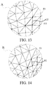
- FIG. 13 is an enlarged schematic view of an embodiment of block A in FIG. 5 ;
- FIG. 14 is an enlarged schematic view of an embodiment of block B in FIG. 12 ;
- FIG. 15 is a schematic view of an example of a texture mapping figure
- FIG. 16 is a flowchart of another embodiment of the three-dimensional head portrait generating method.
- FIG. 17 is a schematic overview of an embodiment of a front face image
- FIG. 18 is a flowchart of an embodiment of step S 70 in FIG. 16 ;
- FIG. 19 is a flowchart of an embodiment of step S 77 in FIG. 18 ;
- FIG. 20 is a schematic overview of an embodiment of a texture mapping figure
- FIG. 21 is a schematic view of an example of a texture mapping figure.
- FIG. 22 is a schematic view of an example of a three-dimensional head portrait.
- a three-dimensional head portrait generating method is applied to an electronic device 100 , so that the electronic device 100 simply and quickly generates a real three-dimensional head portrait 51 that is almost the same as a user (referring to FIG. 22 ).
- the electronic device 100 includes a processing unit 110 , a projection unit 120 , a sensing unit 130 , an image capture unit 140 , and a display unit 150 .
- the processing unit 110 is coupled to the projection unit 120 , the sensing unit 130 , the image capture unit 140 , and the display unit 150 .
- the processing unit 110 enables the projection unit 120 to project radiant light on a user's face U 1 (step S 11 ) and enables the sensing unit 130 to sense reflected light corresponding to the radiant light and reflected from the user's face U 1 (step S 12 ), thereby calculating front face information about depth information of the user's face U 1 according to the reflected light sensed by the sensing unit 130 (step S 13 ).
- the projection unit 120 is implemented by using one or more suitable radiation sources, such as diode lasers and light emitting diodes.
- the radiant light projected by the projection unit 120 is structured light.
- the radiant light projected by the projection unit 120 is invisible light. In some other embodiments, the radiant light projected by the projection unit 120 is visible light.
- the sensing unit 130 is any light sensor corresponding to the projection unit 120 . In an embodiment, when the radiant light projected by the projection unit 120 is infrared light, the sensing unit 130 is an infrared light camera.
- FIG. 4 is a schematic overview of an embodiment of a three-dimensional head portrait model.
- the processing unit 110 after obtaining the front face information with the depth information of the user's face U 1 , the processing unit 110 establishes a three-dimensional head portrait model M 1 corresponding to the user according to the front face information (step S 20 ).
- the established three-dimensional head portrait model M 1 includes a plurality of feature points P 1 corresponding to face features of the user's face U 1 , and the feature points P 1 form a plurality of first grids G 1 on the three-dimensional head portrait model M 1 .
- the processing unit 110 forms the first grids G 1 by a gridding technology of a modeling technology.
- the processing unit 110 uses a Delaunay Triangulation technology to form the plurality of first grids G 1 .
- the feature points P 1 are taken as vertexes of the first grids G 1 to form the plurality of first grids G 1 with triangular shape.
- FIG. 5 is a schematic overview of an embodiment of a left face image
- FIG. 6 is a schematic overview of an embodiment of a right face image.
- the processing unit 110 performs image capture on a left side of the user's face U 1 through the image capture unit 140 to obtain a left face image I 1 including the left side of the user's face U 1 .
- the processing unit 110 maps feature points P 11 of the feature points P 1 on the three-dimensional head portrait model M 1 (that is, the feature points P 11 is a first part of the feature points P 1 ) to the left face image I 1 to form a plurality of second grids G 2 on the left face image I 1 , wherein the feature points P 11 of the feature points P 1 are corresponding to the left side of the user's face U 1 (step S 30 ).
- the processing unit 110 also performs image capture on a right side of the user's face U 1 through the image capture unit 140 to obtain a right face image I 2 including the right side of the user's face U 1 .
- the processing unit 110 correspondingly maps feature points P 12 of the feature points P 1 on the three-dimensional head portrait model M 1 (that is, the feature points P 12 is a second part of the feature points P 1 ) to the right face image I 2 to form a plurality of third grids G 3 on the right face image I 2 , wherein the feature points P 12 corresponding to the right side of the user's face U 1 (step S 40 ).
- the feature points P 11 mapped to the left face image I 1 and the feature points P 12 mapped to the right face image I 2 are partially overlapped (that is, the first part of the feature points P 1 and the second part of the feature points P 1 are partially overlapped).
- the feature points P 11 corresponding to the nose features on the left face image I 1 and the feature points P 12 corresponding to the nose features on the right face image I 2 are mapped from the same feature point P 1 on the three-dimensional head portrait model Ml.
- the image capture unit 140 is an image capturing device with one lens or more lenses and photosensitive components, such as at least one of a complementary metal oxide semiconductor (CMOS) or a charge coupled device (CCD).
- CMOS complementary metal oxide semiconductor
- CCD charge coupled device
- FIG. 7 is a schematic overview of an embodiment where a user's face faces an electronic device directly
- FIG. 8 is a schematic overview of an embodiment where a user's face is right-biased to an electronic device
- FIG. 9 is a schematic overview of an embodiment where a user's face is left-biased to an electronic device.
- the processing unit 110 detects a deflection angle ⁇ existing between the user's face U 1 and the image capture unit 140 by the image capture unit 140 and a real-time image recognition technology, and the processing unit 110 automatically enables the image capture unit 140 to perform image capture on the user's face U 1 to obtain a required left face image I 1 or required right face image I 2 when the processing unit 110 detects the deflection angle ⁇ exiting between the user's face U 1 and the image capture unit 140 is a specific degree.
- the deflection angle ⁇ is zero when the user's face U 1 faces the image capture unit 140 directly, the deflection angle ⁇ has positive degrees when the user's face U 1 turns right relative to the image capture unit 140 , and the deflection angle ⁇ has negative degrees when the user's face U 1 turns left relative to the image capture unit 140 .
- the deflection angle ⁇ is between from 30 degrees to 45 degrees or between from ⁇ 30 degrees to ⁇ 45 degrees.
- step S 30 the processing unit 110 takes the feature points P 11 mapped to the left face image I 1 as the vertexes of the second grid G 2 through the gridding technology to form a plurality of second grids G 2 on the left face image I 1 .
- step S 40 the processing unit 110 takes the feature points P 12 mapped to the right face image I 2 as the vertexes of the third grid G 3 through the gridding technology to form a plurality of third grids G 3 on the right face image I 2 .
- the processing unit 110 forms a plurality of second grids G 2 with triangular shape on the left face image I 1 , and forms a plurality of third grids G 3 with triangular shape on the right face image I 2 .
- Each second grid G 2 corresponds to one of the plurality of first grids G 1 .
- the plurality of feature points P 11 included by each second grid G 2 is the same as the plurality of feature points P 1 included by the corresponding first grid G 1 .
- each third grid G 3 corresponds to one of the plurality of first grids G 1 .
- the plurality of feature points P 12 included by each third grid G 3 is the same as the plurality of feature points P 1 included by the corresponding first grid G 1 .
- the processing unit 110 superimposes the left face image I 1 and the right face image I 2 onto the three-dimensional head portrait model M 1 according to a correspondence among the first grids G 1 , the second grids G 2 and the third grids G 3 to generate a three-dimensional head portrait S 1 of the user (step S 50 ).
- FIG. 10 is a flowchart of an embodiment of step S 50 in FIG. 3
- FIG. 11 is a flowchart of an embodiment of step S 55 in FIG. 10
- FIG. 12 is a schematic overview of an embodiment of a texture mapping figure
- FIG. 13 is an enlarged schematic view of an embodiment of block A in FIG. 5
- FIG. 14 is an enlarged schematic view of an embodiment of block B in FIG. 12
- FIG. 15 is a schematic view of an example of a texture mapping figure.
- the processing unit 110 decomposes the left face image I 1 into a plurality of second grid images I 11 according to the second grids G 2 formed on the left face image I 1 (step S 51 ).
- the processing unit 110 also decomposes the right face image I 2 into a plurality of third grid images 121 according to the third grids G 3 formed on the right face image I 2 (step S 52 ). Afterwards, the processing unit 110 deforms the second grid images I 11 according to the shape and the size of each of the first grids G 1 corresponding to the second grids G 2 (step S 53 ), and deforms the third grid images 121 according to the shape and the size of each of the first grids G 1 corresponding to each third grids G 3 (step S 54 ). Then, the processing unit 110 establishes a texture mapping figure F2 according to the deformed second grid image I 11 ′ and the deformed third grid image I 21 ′ (step S 55 ). Finally, the processing unit 110 superimposes the texture mapping figure F2 onto the three-dimensional head portrait model M 1 to generate a real three-dimensional head portrait S 1 that is almost the same as the user (step S 56 ).
- the processing unit 110 unrolls a curved surface, including the first grids G 1 , of the three-dimensional head portrait model M 1 to a texture mapping figure F 1 that is two-dimensional type.
- the texture mapping figure F 1 has a plurality of texture blocks B 1 , and each texture block B 1 corresponds to one of the plurality of first grids G 1 .
- each texture block B 1 is two-dimensional and corresponding to one of the first grids G 1 of the curved surface.
- a vertex Ti of each texture block B 1 corresponds to the feature point P 1 included by the corresponding first grid G 1 .
- each second grid G 2 is corresponding to one of the first grids G 1 and each texture block B 1 is formed by one of the first grids G 1
- each second grid G 2 is corresponding to one of the texture blocks B 1 .
- each third grid G 3 is corresponding to one of the first grids G 1 and each texture block B 1 is formed by one of the first grids G 1
- each third grid G 3 is corresponding to one of the texture blocks B 1 .
- mapping transformation such as a combination of translation, rotation, scaling, reflection, or transvection.
- each feature point P 11 on the left face image I 1 has corresponding two-dimensional coordinates
- the vertex T 1 of each texture block B 1 has corresponding texture mapping coordinates
- the processing unit 110 maps the feature points P 11 included by each second grid G 2 to the vertex T 1 of the corresponding texture block B 1 by matrix transformation, so that the shape and the size of each of the second grid image I 11 decomposed by each second grid G 2 is the same as the shape and the size of the corresponding texture block B 1 by deforming each the second grid image I 11 .
- each feature point P 12 on the right face image I 2 also has corresponding two-dimensional coordinates
- the processing unit 110 maps the feature points P 12 included by each third grid G 3 to the vertex Ti of the corresponding texture block B 1 by matrix transformation, so that the shape and the size of each of the third grid image I 21 decomposed by each third grid G 3 is the same as the shape and the size of the corresponding texture block B 1 by deforming each third grid image I 21 .
- the texture mapping figure F1 comprises a left texture figure F11 , a central texture figure F12 and a right texture figure F13 connected in sequence from right to left.
- the deformed second grid images I 11 ' are divided into first deformed second grid images and second deformed second grid images
- the deformed third grid images I 21 ′ are divided into first deformed third grid images and second deformed third grid images.
- each of the first deformed second grid images corresponds to one of the plurality of texture blocks B 1 in the left texture figure F 11
- each of the second deformed second grid images corresponds to one of the plurality of texture blocks B 1 in the central texture figure F 12
- each of the first deformed third grid images corresponds to one of the plurality of texture blocks B 1 in the right texture figure F 13
- each of the second deformed third grid images corresponds to one of the plurality of texture blocks B 1 in the central texture figure F 12
- each texture block B 1 in the central texture figure F 12 corresponds to one of the second deformed second grid image and one of the second deformed third grid image respectively.
- step S 55 the processing unit 110 superimposes each of the first deformed second grid images onto the corresponding texture block B 1 in the left texture figure F11 (step S 55 A) to form a left texture figure F21 , and superimposes each of the first deformed third grid images onto the corresponding texture blocks B 1 in the right texture figure F13 (step S 55 B) to form a right texture figure F23 .
- the processing unit 110 blends the second deformed second grid images and the second deformed third grid images corresponding to the texture blocks B 1 of the central texture figure F12 , to form fourth grid images I 31 ′ according to a first weight and a second weight of each texture block B 1 in the central texture figure F12 , wherein the first weight is used for the second deformed second grid image and the second weight is used for the second deformed third grid images (step S 55 C). Then, the processing unit 110 superimposes all fourth grid images I 31 ′ generated in step S 55 C onto the central texture figure F12 (step S 55 D) to form the established central texture figure F22 to complete establishment of the whole texture mapping figure F2 . An example of the completed texture mapping figure F2 is shown in FIG. 15 .
- the first weight and the second weight of one texture block B 1 are different from the first weight and the second weight of another texture block B 1 , but a total value of the first weight and the second weight of each texture block B 1 is 1.
- a first weight of the texture block B 1 is 0.75
- second weight of the texture block B 1 is 0.25. Therefore, in the fourth grid image I 31 ′ blended by the second deformed second grid image and the second deformed third grid image corresponding to the texture block B 1 , the ratio of the second deformed second grid image is higher than that of the second deformed third grid image.
- FIG. 16 is a flowchart of another embodiment of a three-dimensional head portrait generating method
- FIG. 17 is a schematic overview of an embodiment of a front face image.
- the processing unit 110 generates a three-dimensional head portrait S 1 according to the front face image 15 , the left face image I 1 and the right face image I 2 , so that the generated three-dimensional head portrait S 1 is more accurate.
- step S 11 to step S 40 are substantially the same as those in the foregoing embodiment, they will not be described again.
- the processing unit 110 further performs image capture on a front side of the user's face U 1 through the image capture unit 140 to obtain a front face image I 5 including the front side of the user's face U 1 .
- the processing unit 110 maps feature points P 13 of the feature points P 1 on the three-dimensional head portrait model M 1 (that is, the feature points P 13 is a third part of the feature points P 1 ) to the front face image I 5 to form a plurality of fifth grids G 5 on the front face image I 5 , the feature points P 13 of the feature points P 1 are corresponding to the front side of the user's face U 1 (step S 60 ).
- the feature points P 13 mapped to the front face image I 5 , the feature points P 11 mapped to the left face image I 1 and the feature points P 12 mapped to the right face image I 2 are partially overlapped (that is, the first part of the feature points P 1 , the second part of the feature points P 1 and the third part of the feature points P 1 are partially overlapped).
- the feature points P 13 corresponding to the lip features on the front face image I 5 are mapped from the same feature point P 1 on the three-dimensional head portrait model M 1 .
- the processing unit 110 detects a deflection angle ⁇ existing between the user's face U 1 and the image capture unit 140 by the image capture unit 140 and a real-time image recognition technology, and the processing unit 110 automatically enables the image capture unit 140 to perform image capture on the user's face U 1 to obtain a required front face image 15 when the processing unit 110 detects the deflection angle ⁇ exiting between the user's face U 1 and the image capture unit 140 is a specific degree.
- the deflection angle ⁇ is between from 10 degrees to ⁇ 10 degrees.
- step S 60 the processing unit 110 takes the feature points P 13 mapped to the front face image I 5 as the vertexes of the fifth grids G 5 through the gridding technology to form a plurality of fifth grids G 5 on the front face image I 5 .
- the processing unit 110 forms a plurality of fifth grids G 5 with triangular shape on the front face image I 5 .
- Each fifth grid G 5 corresponds to one of the plurality of first grids G 1 . Moreover, the plurality of feature points P 13 included by each fifth grid G 5 is the same as the plurality of feature points P 1 included by the corresponding first grid G 1 .
- the processing unit 110 superimposes the left face image I 1 , the right face image I 2 and the front face image I 5 in the three-dimensional head portrait model M 1 according to a correspondence among the first grids G 1 , the second grids G 2 , the third grids G 3 and the fifth grids G 5 to generate a three-dimensional head portrait S 1 of the user (step S 70 ).
- FIG. 18 is a flowchart of an embodiment of step S 70 in FIG. 16
- FIG. 19 is a flowchart of an embodiment of step S 77 in FIG. 18
- FIG. 20 is a schematic overview of an embodiment of a texture mapping figure
- FIG. 21 is a schematic view of an example of a texture mapping figure. Referring to FIG. 1 to FIG.
- step S 70 the processing unit 110 decomposes the left face image I 1 into a plurality of second grid images I 11 according to the second grids G 2 formed on the left face image I 1 (step S 71 ), decomposes the right face image I 2 into a plurality of third grid images I 21 according to the third grids G 3 formed on the right face image I 2 (step S 72 ), and decomposes the front face image I 5 into a plurality of fifth grid images I 51 according to the fifth grids G 5 formed on the front face image I 5 (step S 73 ).
- the processing unit 110 deforms the second grid images I 11 according to the shape size of the first grids G 1 corresponding to the second grids G 2 (step S 74 ), deforms the third grid images 121 according to the shape size of the first grids G 1 corresponding to the third grids G 3 (step S 75 ), and deforms the fifth grid images I 51 according to the shape size of the first grids G 1 corresponding to the fifth grids G 5 (step S 76 ). Then, the processing unit 110 establishes a texture mapping figure F2 according to the deformed second grid images I 11 ′, the deformed third grid images I 21 ′ and the deformed fifth grid images I 51 ′ (step S 77 ). Finally, the processing unit 110 superimposes the texture mapping figure F2 onto the three-dimensional head portrait model M 1 to generate a real three-dimensional head portrait S 1 that is almost the same as the user (step S 78 ).
- the processing unit 110 unrolls a curved surface, including the first grids G 1 , of the three-dimensional head portrait model M 1 to a texture mapping figure F 1 in two-dimensional type.
- the texture mapping figure F 1 has a plurality of texture blocks B 1 , and each texture block B 1 corresponds to one of the plurality of first grids G 1 .
- each texture block B 1 is two-dimensional and corresponding to one of the first grids G 1 of the curved surface. Since each second grid G 2 is corresponding to one of the first grids G 1 and each texture block B 1 is formed by one of the first grids G 1 , each second grid G 2 is corresponding to one of the texture blocks B 1 .
- each third grid G 3 is corresponding to one of the first grids G 1 and each texture block B 1 is formed by one of the first grids G 1
- each third grid G 3 is corresponding to one of the texture blocks B 1
- each fifth grid G 5 is corresponding to one of the first grids G 1 and each texture block B 1 is formed by one of the first grids G 1
- each fifth grid G 5 is corresponding to one of the texture blocks B 1 .
- the processing unit 110 also deforms the second grid image I 11 , the third grid image I 21 and the fifth grid image I 51 by mapping transformation, such as a combination of translation, rotation, scaling, reflection, or transvection.
- each feature point P 13 on the front face image I 5 has corresponding two-dimensional coordinates
- the vertex T 1 of each texture block B 1 has corresponding texture mapping coordinates
- the processing unit 110 maps the feature points P 13 included by each fifth grid G 5 to the vertex T 1 of the corresponding texture block B 1 by matrix transformation, so that the shape size of the fifth grid image I 51 decomposed by each fifth grid G 5 is the same as the shape size of the corresponding texture block B 1 by deforming the fifth grid image I 51 .
- the deformation of the second grid image I 11 and the third grid image I 21 are referred to the foregoing description, and therefore will not be described again.
- the texture mapping figure F1 comprises a left texture figure F11 , a first blended texture figure F14 , a central texture figure F12 , a second blended texture figure F15 and a right texture figure F13 connected in sequence from right to left.
- the deformed second grid images I 11 ′ are divided into first deformed second grid images and second deformed second grid images
- the deformed third grid images I 21 ′ are divided into first deformed third grid images and second deformed third grid images
- the deformed fifth grid images I 51 ′ are divided into first deformed fifth grid images, second deformed fifth grid images and third deformed fifth grid images.
- Each of the first deformed second grid images corresponds to one of the plurality of texture blocks B 1 in the left texture figure F 11
- each of the second deformed second grid images corresponds to one of the plurality of texture blocks B 1 in the first blended texture figure F 14
- Each of the first deformed third grid images corresponds to one of the plurality of texture blocks B 1 in the right texture figure F 13
- each of the second deformed third grid images corresponds to one of the plurality of texture blocks B 1 in the second blended texture figure F 15 .
- each of the first deformed fifth grid images corresponds to the central texture figure F 12
- each of the second deformed fifth grid images corresponds to one of the plurality of texture blocks B 1 in the first blended texture figure F 14
- each of the third deformed fifth grid images corresponds to one of the plurality of texture blocks B 1 in the second blended texture figure F 15
- each texture block B 1 in the first blended texture figure F 14 corresponds to one of the second deformed second grid image and one of the second deformed fifth grid images respectively
- each texture block B 1 in the second blended texture figure F 15 corresponds to one of the second deformed third grid images and one of the third deformed fifth grid images' respectively.
- step S 77 the processing unit 110 superimposes each of the first deformed second grid images onto the corresponding texture blocks B 1 in the left texture figure F 11 (step S 77 A) to form a left texture figure F 21 , superimposes each of the first deformed third grid images onto the corresponding texture blocks B 1 in the right texture figure F 13 (step S 77 B) to form a right texture figure F 23 , and superimposes each of the first deformed fifth grid images onto the central texture figure F 12 (step S 77 C) to form a central texture figure F 22 .
- the processing unit 110 blends the second deformed second grid images and the second deformed fifth grid images corresponding to the texture blocks B 1 of the first blended texture figure F 14 to form sixth grid images I 61 ′ according to a third weight and a fourth weight of each texture block B 1 in the first blended texture figure F 14 , wherein the third weight is used for the second deformed second grid images and the fourth weight is used for the second deformed fifth grid images (step S 77 D).
- the third weight and the fourth weight of one texture block B 1 are different from the third weight and the fourth weight of another texture block B 1 , but a total value of the third weight and the fourth weight of each texture block B 1 is 1.
- the processing unit 110 blends the second deformed third grid images and the third deformed fifth grid images corresponding to the texture blocks B 1 of the second blended texture figure F 15 to form seventh grid images I 71 ′ according to a fifth weight and a sixth weight of each texture block B 1 in the second blended texture figure F 15 , wherein the fifth weight is used for the third grid image I 21 ′ and the sixth weight is used for the fifth grid image I 51 ′ (step S 77 E).
- the fifth weight and the sixth weight corresponding of one texture block B 1 are different from the fifth weight and the sixth weight of another texture block B 1 , but a total value of the fifth weight and the sixth weight of each texture block B 1 is 1.
- the processing unit 110 superimposes all the sixth grid images I 61 ′ generated in step S 77 D onto the first blended texture figure F14 (step S 77 F) to form a first blended texture figure F24 , and superimposes all the seventh grid images I 71 ′ generated in step S 77 E onto the second blended texture figure F15 (step S 77 G) to form a second blended texture figure F25 , so as to complete establishment of the whole texture mapping figure F2 .
- An example of the completed texture mapping figure F2 is shown in FIG. 21 .
- the three-dimensional head portrait generating method of any embodiment of the invention is implemented by a non-transitory readable memory medium.
- the non-transitory readable memory medium stores a plurality of program codes, when an electronic device 100 loads and executes the plurality of program codes, the program codes cause the electronic device 100 to execute the three-dimensional head portrait generating method of any one of the foregoing embodiments.
- the non-transitory readable memory medium is a storage component 160 inside the electronic device 100 .
- the storage component 160 is a read-only memory (ROM) or a flash memory.
- the non-transitory readable memory medium is a remote storage component, and is transmitted into the electronic device 100 in a wired or wireless manner.
- the non-transitory readable memory medium is a storage component outside the electronic device 100 , and the program codes in the storage component are accessed by connection of a reader or a connector of the electronic device 100 .
- the processing unit 110 After the processing unit 110 generates the three-dimensional head portrait S 1 , the three-dimensional head portrait S 1 is output to the display unit 150 for display.
- the display unit 150 is any suitable display screen such as an LCD screen or an LED screen.
- the processing unit 110 After the processing unit 110 generates the three-dimensional head portrait S 1 , the three-dimensional head portrait is stored in the storage component 160 of the electronic device 100 , and the established three-dimensional head portrait S 1 is used for the user to perform various applications subsequently. In an embodiment, when another user uses the electronic device 100 , the established three-dimensional head portrait S 1 is changed according to a current facial expression of another user, such as opening the mouth or closing the eyes.
- the three-dimensional head portrait S 1 generated by the processing unit 110 is used in any application of augmented reality (AR), and in an embodiment, the three-dimensional head portrait S 1 is applied to application services such as virtual plastic surgery and virtual makeup.
- AR augmented reality
- the processing unit 110 is implemented by using a system on chip (SoC), a central processing unit (CPU), a micro control unit (MCU) or an application specific integrated circuit (ASIC).
- SoC system on chip
- CPU central processing unit
- MCU micro control unit
- ASIC application specific integrated circuit
- the electronic device 100 is a smart phone, a notebook computer, a tablet computer, or other suitable electronic devices.
- second grids and third grids corresponding to first grids on a three-dimensional head portrait model are separately defined on a left face image and a right face image, and the left face image and the right face image are combined in the three-dimensional head portrait model according to a correspondence between the first grids, the second grids and the third grids, thereby effectively shortening the matching and superimposing time for an electronic device to more simply and quickly calculate a real three-dimensional head portrait that is almost the same as a user.
Landscapes
- Engineering & Computer Science (AREA)
- Physics & Mathematics (AREA)
- General Physics & Mathematics (AREA)
- Theoretical Computer Science (AREA)
- Computer Graphics (AREA)
- Software Systems (AREA)
- Geometry (AREA)
- Computer Vision & Pattern Recognition (AREA)
- Health & Medical Sciences (AREA)
- Oral & Maxillofacial Surgery (AREA)
- Multimedia (AREA)
- Optics & Photonics (AREA)
- General Health & Medical Sciences (AREA)
- Human Computer Interaction (AREA)
- Processing Or Creating Images (AREA)
- Image Processing (AREA)
Abstract
Description
Claims (17)
Applications Claiming Priority (2)
| Application Number | Priority Date | Filing Date | Title |
|---|---|---|---|
| CN201810502084.7 | 2018-05-23 | ||
| CN201810502084 | 2018-05-23 |
Publications (2)
| Publication Number | Publication Date |
|---|---|
| US20190362547A1 US20190362547A1 (en) | 2019-11-28 |
| US11120624B2 true US11120624B2 (en) | 2021-09-14 |
Family
ID=68613778
Family Applications (1)
| Application Number | Title | Priority Date | Filing Date |
|---|---|---|---|
| US16/414,974 Active US11120624B2 (en) | 2018-05-23 | 2019-05-17 | Three-dimensional head portrait generating method and electronic device |
Country Status (2)
| Country | Link |
|---|---|
| US (1) | US11120624B2 (en) |
| CN (2) | CN110533761B (en) |
Families Citing this family (4)
| Publication number | Priority date | Publication date | Assignee | Title |
|---|---|---|---|---|
| CN109919876B (en) * | 2019-03-11 | 2020-09-01 | 四川川大智胜软件股份有限公司 | Three-dimensional real face modeling method and three-dimensional real face photographing system |
| CN113436301B (en) * | 2020-03-20 | 2024-04-09 | 华为技术有限公司 | Method and device for generating anthropomorphic 3D model |
| CN111696178A (en) * | 2020-05-06 | 2020-09-22 | 广东康云科技有限公司 | Method, device and medium for generating portrait three-dimensional model and simulated portrait animation |
| CN117853691A (en) * | 2023-12-27 | 2024-04-09 | 北京达美盛软件股份有限公司 | Graphic processing method and system of three-dimensional model |
Citations (13)
| Publication number | Priority date | Publication date | Assignee | Title |
|---|---|---|---|---|
| US20060067573A1 (en) * | 2000-03-08 | 2006-03-30 | Parr Timothy C | System, method, and apparatus for generating a three-dimensional representation from one or more two-dimensional images |
| US20100215255A1 (en) * | 2009-02-25 | 2010-08-26 | Jing Xiao | Iterative Data Reweighting for Balanced Model Learning |
| CN104376599A (en) | 2014-12-11 | 2015-02-25 | 苏州丽多网络科技有限公司 | Handy three-dimensional head model generation system |
| CN104915981A (en) | 2015-05-08 | 2015-09-16 | 寇懿 | Three-dimensional hairstyle design method based on somatosensory sensor |
| US20160148425A1 (en) * | 2014-11-25 | 2016-05-26 | Samsung Electronics Co., Ltd. | Method and apparatus for generating personalized 3d face model |
| US20170018088A1 (en) * | 2015-07-14 | 2017-01-19 | Samsung Electronics Co., Ltd. | Three dimensional content generating apparatus and three dimensional content generating method thereof |
| CN106910247A (en) | 2017-03-20 | 2017-06-30 | 厦门幻世网络科技有限公司 | Method and apparatus for generating three-dimensional head portrait model |
| US20170212661A1 (en) * | 2016-01-25 | 2017-07-27 | Adobe Systems Incorporated | 3D Model Generation from 2D Images |
| US20170345183A1 (en) * | 2016-04-27 | 2017-11-30 | Bellus 3D, Inc. | Robust Head Pose Estimation with a Depth Camera |
| US20180005018A1 (en) * | 2016-06-30 | 2018-01-04 | U.S. Army Research Laboratory Attn: Rdrl-Loc-I | System and method for face recognition using three dimensions |
| US20190035149A1 (en) * | 2015-08-14 | 2019-01-31 | Metail Limited | Methods of generating personalized 3d head models or 3d body models |
| US20200258206A1 (en) * | 2017-11-22 | 2020-08-13 | Tencent Technology (Shenzhen) Company Limited | Image fusion method and device, storage medium and terminal |
| US10991110B2 (en) * | 2016-12-06 | 2021-04-27 | Activision Publishing, Inc. | Methods and systems to modify a two dimensional facial image to increase dimensional depth and generate a facial image that appears three dimensional |
Family Cites Families (11)
| Publication number | Priority date | Publication date | Assignee | Title |
|---|---|---|---|---|
| CN100353384C (en) * | 2004-12-30 | 2007-12-05 | 中国科学院自动化研究所 | Fast method for posting players to electronic game |
| US7756325B2 (en) * | 2005-06-20 | 2010-07-13 | University Of Basel | Estimating 3D shape and texture of a 3D object based on a 2D image of the 3D object |
| AU2008200301A1 (en) * | 2008-01-22 | 2009-08-06 | The University Of Western Australia | Image recognition |
| US8570343B2 (en) * | 2010-04-20 | 2013-10-29 | Dassault Systemes | Automatic generation of 3D models from packaged goods product images |
| KR102294927B1 (en) * | 2014-03-31 | 2021-08-30 | 트라이큐빅스 인크. | Sns . |
| EP3032495B1 (en) * | 2014-12-10 | 2019-11-13 | Dassault Systèmes | Texturing a 3d modeled object |
| JP6574401B2 (en) * | 2016-04-08 | 2019-09-11 | ソフトバンク株式会社 | Modeling control system, modeling control method, and modeling control program |
| CN106327571B (en) * | 2016-08-23 | 2019-11-05 | 北京的卢深视科技有限公司 | A kind of three-dimensional face modeling method and device |
| CN107085654B (en) * | 2017-04-06 | 2021-04-02 | 深圳创维-Rgb电子有限公司 | Health analysis method and device based on face image |
| CN107563328A (en) * | 2017-09-01 | 2018-01-09 | 广州智慧城市发展研究院 | A kind of face identification method and system based under complex environment |
| CN107784630B (en) * | 2017-11-08 | 2021-11-23 | 北京奇虎科技有限公司 | Method, device and terminal for turning attributes of face image |
-
2018
- 2018-10-09 CN CN201811171169.8A patent/CN110533761B/en active Active
-
2019
- 2019-01-21 CN CN201910052817.6A patent/CN110533762B/en active Active
- 2019-05-17 US US16/414,974 patent/US11120624B2/en active Active
Patent Citations (13)
| Publication number | Priority date | Publication date | Assignee | Title |
|---|---|---|---|---|
| US20060067573A1 (en) * | 2000-03-08 | 2006-03-30 | Parr Timothy C | System, method, and apparatus for generating a three-dimensional representation from one or more two-dimensional images |
| US20100215255A1 (en) * | 2009-02-25 | 2010-08-26 | Jing Xiao | Iterative Data Reweighting for Balanced Model Learning |
| US20160148425A1 (en) * | 2014-11-25 | 2016-05-26 | Samsung Electronics Co., Ltd. | Method and apparatus for generating personalized 3d face model |
| CN104376599A (en) | 2014-12-11 | 2015-02-25 | 苏州丽多网络科技有限公司 | Handy three-dimensional head model generation system |
| CN104915981A (en) | 2015-05-08 | 2015-09-16 | 寇懿 | Three-dimensional hairstyle design method based on somatosensory sensor |
| US20170018088A1 (en) * | 2015-07-14 | 2017-01-19 | Samsung Electronics Co., Ltd. | Three dimensional content generating apparatus and three dimensional content generating method thereof |
| US20190035149A1 (en) * | 2015-08-14 | 2019-01-31 | Metail Limited | Methods of generating personalized 3d head models or 3d body models |
| US20170212661A1 (en) * | 2016-01-25 | 2017-07-27 | Adobe Systems Incorporated | 3D Model Generation from 2D Images |
| US20170345183A1 (en) * | 2016-04-27 | 2017-11-30 | Bellus 3D, Inc. | Robust Head Pose Estimation with a Depth Camera |
| US20180005018A1 (en) * | 2016-06-30 | 2018-01-04 | U.S. Army Research Laboratory Attn: Rdrl-Loc-I | System and method for face recognition using three dimensions |
| US10991110B2 (en) * | 2016-12-06 | 2021-04-27 | Activision Publishing, Inc. | Methods and systems to modify a two dimensional facial image to increase dimensional depth and generate a facial image that appears three dimensional |
| CN106910247A (en) | 2017-03-20 | 2017-06-30 | 厦门幻世网络科技有限公司 | Method and apparatus for generating three-dimensional head portrait model |
| US20200258206A1 (en) * | 2017-11-22 | 2020-08-13 | Tencent Technology (Shenzhen) Company Limited | Image fusion method and device, storage medium and terminal |
Also Published As
| Publication number | Publication date |
|---|---|
| US20190362547A1 (en) | 2019-11-28 |
| CN110533761A (en) | 2019-12-03 |
| CN110533762A (en) | 2019-12-03 |
| CN110533762B (en) | 2023-04-21 |
| CN110533761B (en) | 2024-01-12 |
Similar Documents
| Publication | Publication Date | Title |
|---|---|---|
| US11120624B2 (en) | Three-dimensional head portrait generating method and electronic device | |
| CN109118569B (en) | Rendering method and device based on three-dimensional model | |
| US20210118159A1 (en) | Method and device for image processing | |
| CN109074660B (en) | Method and system for real-time three-dimensional capture and instant feedback of monocular camera | |
| JP4284664B2 (en) | Three-dimensional shape estimation system and image generation system | |
| Kemelmacher-Shlizerman et al. | 3D face reconstruction from a single image using a single reference face shape | |
| Wechsler | Reliable Face Recognition Methods: System Design, Impementation and Evaluation | |
| CN111710036B (en) | Method, device, equipment and storage medium for constructing three-dimensional face model | |
| Hsu et al. | Face modeling for recognition | |
| US10789784B2 (en) | Image display method, electronic device, and non-transitory computer readable recording medium for quickly providing simulated two-dimensional head portrait as reference after plastic operation | |
| WO2019035155A1 (en) | Image processing system, image processing method, and program | |
| KR20170008638A (en) | Three dimensional content producing apparatus and three dimensional content producing method thereof | |
| WO2024007478A1 (en) | Three-dimensional human body modeling data collection and reconstruction method and system based on single mobile phone | |
| CN111652123B (en) | Image processing and image synthesizing method, device and storage medium | |
| CN112348937A (en) | Face image processing method and electronic equipment | |
| CN113628327A (en) | Head three-dimensional reconstruction method and equipment | |
| WO2019157989A1 (en) | Biological feature 3d data acquisition method and biological feature 3d data recognition method | |
| CN112784621A (en) | Image display method and apparatus | |
| JP2024525703A (en) | Three-dimensional dynamic tracking method, device, electronic device and storage medium | |
| WO2019075656A1 (en) | Image processing method and device, terminal, and storage medium | |
| WO2023066120A1 (en) | Image processing method and apparatus, electronic device, and storage medium | |
| WO2020134925A1 (en) | Illumination detection method and apparatus for facial image, and device and storage medium | |
| KR20200100020A (en) | Three dimensional content producing apparatus and three dimensional content producing method thereof | |
| CN115482359A (en) | Method for measuring size of object, electronic device and medium thereof | |
| JP5092093B2 (en) | Image processing device |
Legal Events
| Date | Code | Title | Description |
|---|---|---|---|
| AS | Assignment |
Owner name: ASUSTEK COMPUTER INC., TAIWAN Free format text: ASSIGNMENT OF ASSIGNORS INTEREST;ASSIGNORS:LEE, GUAN-DE;KUO, HAO-YUAN;REEL/FRAME:049208/0119 Effective date: 20190517 |
|
| FEPP | Fee payment procedure |
Free format text: ENTITY STATUS SET TO UNDISCOUNTED (ORIGINAL EVENT CODE: BIG.); ENTITY STATUS OF PATENT OWNER: LARGE ENTITY |
|
| STPP | Information on status: patent application and granting procedure in general |
Free format text: DOCKETED NEW CASE - READY FOR EXAMINATION |
|
| STPP | Information on status: patent application and granting procedure in general |
Free format text: NON FINAL ACTION MAILED |
|
| STPP | Information on status: patent application and granting procedure in general |
Free format text: NON FINAL ACTION MAILED |
|
| STPP | Information on status: patent application and granting procedure in general |
Free format text: RESPONSE TO NON-FINAL OFFICE ACTION ENTERED AND FORWARDED TO EXAMINER |
|
| STPP | Information on status: patent application and granting procedure in general |
Free format text: NOTICE OF ALLOWANCE MAILED -- APPLICATION RECEIVED IN OFFICE OF PUBLICATIONS |
|
| STPP | Information on status: patent application and granting procedure in general |
Free format text: PUBLICATIONS -- ISSUE FEE PAYMENT VERIFIED |
|
| STCF | Information on status: patent grant |
Free format text: PATENTED CASE |