US1111963A - Spark-gap. - Google Patents
Spark-gap. Download PDFInfo
- Publication number
- US1111963A US1111963A US79395613A US1111963DA US1111963A US 1111963 A US1111963 A US 1111963A US 79395613 A US79395613 A US 79395613A US 1111963D A US1111963D A US 1111963DA US 1111963 A US1111963 A US 1111963A
- Authority
- US
- United States
- Prior art keywords
- spark
- gap
- rod
- opening
- plug
- Prior art date
- Legal status (The legal status is an assumption and is not a legal conclusion. Google has not performed a legal analysis and makes no representation as to the accuracy of the status listed.)
- Expired - Lifetime
Links
- 238000010276 construction Methods 0.000 description 3
- 238000002485 combustion reaction Methods 0.000 description 2
- 239000000835 fiber Substances 0.000 description 2
- 239000011521 glass Substances 0.000 description 2
- 239000000463 material Substances 0.000 description 2
- 230000000284 resting effect Effects 0.000 description 2
- 241000251468 Actinopterygii Species 0.000 description 1
- 239000011810 insulating material Substances 0.000 description 1
- 229910052573 porcelain Inorganic materials 0.000 description 1
- 238000005728 strengthening Methods 0.000 description 1
- 210000003813 thumb Anatomy 0.000 description 1
Images
Classifications
-
- H—ELECTRICITY
- H01—ELECTRIC ELEMENTS
- H01T—SPARK GAPS; OVERVOLTAGE ARRESTERS USING SPARK GAPS; SPARKING PLUGS; CORONA DEVICES; GENERATING IONS TO BE INTRODUCED INTO NON-ENCLOSED GASES
- H01T1/00—Details of spark gaps
Definitions
- the object of my' invention is to provide a spark gap of simple, durable ⁇ and inexpensive construction especially designed to he mounted on a spark plug of an internal. combustion engine.
- a sci ew threaded rod 16 the'inneglend of which extends into the opening. 13' 5 5 and lthe outer end-of which is provided with a notch 17 to receive a screw driver.
- Mounted on the ⁇ body 12 is a hollow eyl- 2Q non-conducting transparent material-'which seats against the Han Ve 14 as a shoulder and' preferably extends fish withA the edgejlof the .opposite end of the body 14,A as shown in Fig. 2.
- the portion 24 is secured to the spark plug and the rod 16 to the current carrying Wire 26.
- the rod 24' is arranged to project into the opening'l. It will readilyl be seen that by loosening the nuts .19 and 18, the rod 16 may be screwed vinto or out of the body 12 for varyingthe distance between the inner ends of the rods 16 and 24.
- the engineer may ascertain at a glan'ce which, if any, of the spark plugs are not working properly and can also easily determine the s trengthof thel spark which he is obtaining .in each plug. While the spark in the gap and the'spark in the 11o v plug are' not exactly the same they have a definite relation so that with a little experience the engineer can determine from the spark in the gap what spark he is obtaining in the plug.
- the cylinders 2O may be purchased ata very small vprice and the other parts are comparatively inexpensive so that theQeostl of manufacturi ing my spark gap is very small, due to the simplicity of the parts. No screws are needed except those which are formed on the current conducting rods.
- Another advantage of my gap lies in the fact that the current conducting rods are thoroughly insulated over their portions ad jacent to their inner ends.
- spark gap comprising a cylinder made of insulating material and having a transverse opening extending through it and a longitudinal opening extending through it, said cylinder being formed with an an 'nular flange at one end, a hollow cylindrical transparent body mounted on said cylinder resting against said flange, a cap on sald transparent cylinder and said first cylinder on the ends thereof opposite saidl formed with an annular flange at one end,
- a transparent cylinder received on said body and resting against said Harige, and a cap .on said body and on said cylinder on the end of the body opposite the fiange, one of said .screw threaded rods being provided with a flange for holding said cap in position for lecdlliring said transparentcylinder on said Des Moines, Iowa, September 25, 1913.
Landscapes
- Spark Plugs (AREA)
Description
' .eo'r'rLIEBr KNoma, ornns MoINEsgowA.
sPAnx-GAP.
Specification of Letters Patent. l Patented Sept. 29, 1914.
Application mea october a, 1913, serial' No. 793,956.
To all whom t may concern Be it known'that I, Go'rrrmn F. KNoRR, a. citizen' ofthe United States, residing at Des Moines, in the county of Polk and State of Iowa, have invented a certain new and useful Spark-Gap, of which the following is a specification.
The object of my' invention is to provide a spark gap of simple, durable` and inexpensive construction especially designed to he mounted on a spark plug of an internal. combustion engine.
MoreA particularly, it is my object to provide a spark gap which may be placed in an parent means whereby the spark. may be watched.
Still a further object is to provide a spark gap of the kind mentioned so constructed that it 'may' be placed in an electric circuit with the spark or insulating parts, and with parts so constructed and arranged as to vary the length of the gap.
I Still a further object is toprovide such a device having means especially adapted to be mounted on a vspark plug and designed for strengthening the spark on the interior of the cylinder.
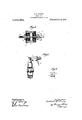
My invention consists in certain details, in the construction, arrangement and combination of the various parts of the device, whereby the objects contemplated are attained, as hereinafter more fully set forth, pointed out in my claims, and illustrated in the accompan ing drawings, in which: Figure 1 shows a side elevation of a spark gapembodying my invention installed on aA spark plug. Fig.' 2 shows a vertical longi- 1 tudinal, sectional view through the spark gap, and Fig. 3 shows a side elevation of the fiber body forming a part of my spark gap.
1n the accompanying drawing. Ihave used the reference numeral to indicate generally a spark plug which maybe of the ordinary construction provided with ordinary screw threaded wire or rod at its outer end to receive a nut 11.
' My improved spark gap. comprises a body 12 made of fiber or other suitable insulating' material .which may be `readily molded. The body 12 is preferably cylindrical and is provided 'with a transverse cylindricall opening extending through it from side to electric circuit and is provided with transinder 20 preferably of glass. or othersuitable side and with a longitudinal, central open ing 15,- shown by the dotted lines in Fig-3, extending through it from endl to end and preferably screw threaded. Formed on one end of the body 12 isa cireumferentialv `annular flange 14.. The Q0 opening extends through thaange '14.' Received in the opening 15 and extend-ing. through the ange 14 anda portion of the i body. 12 is a sci ew threaded rod 16 the'inneglend of which extends into the opening. 13' 5 5 and lthe outer end-of which is provided with a notch 17 to receive a screw driver. A On the screw threaded rod 16 .is an ordinary. nut- 18 and a thumb nut 19 4' Mounted on the` body 12 is a hollow eyl- 2Q non-conducting transparent material-'which seats against the Han Ve 14 as a shoulder and' preferably extends fish withA the edgejlof the .opposite end of the body 14,A as shown in Fig. 2. Received on the end of the body.' 12 opposite the flange 14 and onthe end of the glass casing or cylinder 20 is a retainingl cap 21 having a central opening which regis' ters with the opening 15. Received in the-; opening in the cap 21 and lextendipg'into the opening 1 5 in the body 12 as far as the opening 13 -is a screw threaded 'rod 22; formed on said rod just outside the cap 21 is va circumferential annular fiange 23. Formed on said rod beyond the flange 23 is a fiat portion 24 having a screw threaded opening 25 designed to be received on the screw threaded outer end of the current conducting wire or rod of a spark plug in the manner shown in Fig. 1. A current conducting wire 26. may be also secured to the rod 16 between the nuts 18 and 19, as shown in Fig. 1.
In the practical use 'of my improved 96 spark gap, the portion 24 is secured to the spark plug and the rod 16 to the current carrying Wire 26. The rod 24'is arranged to project into the opening'l. It will readilyl be seen that by loosening the nuts .19 and 18, the rod 16 may be screwed vinto or out of the body 12 for varyingthe distance between the inner ends of the rods 16 and 24.
When my spark gap is'used on an internal combustion engine, the engineer may ascertain at a glan'ce which, if any, of the spark plugs are not working properly and can also easily determine the s trengthof thel spark which he is obtaining .in each plug. While the spark in the gap and the'spark in the 11o v plug are' not exactly the same they have a definite relation so that with a little experience the engineer can determine from the spark in the gap what spark he is obtaining in the plug.
My improved spark gap hasa number of advantages. It utilizes the well known electrical phenomenon that, where the current is broken or forced to jump the gap, the spark at the next gap will be stronger than would otherwise be the case. I have therefore found it to be a fact that by the use of my gap, I can increase the strength of the spark in the plug. Where my spark gap is used the currentthereafter will follow the conducting wire or rod more readily and a spark plug will work in oil or with a broken porcelain. I am therefore enabled to make a considerable saving in making it possible to use plugs that would otherwise have to be discarded. The bodies l2 may be molded or turned out at a very small expense for labor or material. The cap 21 is preferably formed with a die. The cylinders 2O may be purchased ata very small vprice and the other parts are comparatively inexpensive so that theQeostl of manufacturi ing my spark gap is very small, due to the simplicity of the parts. No screws are needed except those which are formed on the current conducting rods.
Another advantage of my gap lies in the fact that the current conducting rods are thoroughly insulated over their portions ad jacent to their inner ends.
I claim as my invention: y
1. spark gap, comprising a cylinder made of insulating material and having a transverse opening extending through it and a longitudinal opening extending through it, said cylinder being formed with an an 'nular flange at one end, a hollow cylindrical transparent body mounted on said cylinder resting against said flange, a cap on sald transparent cylinder and said first cylinder on the ends thereof opposite saidl formed with an annular flange at one end,
a transparent cylinder received on said body and resting against said Harige, and a cap .on said body and on said cylinder on the end of the body opposite the fiange, one of said .screw threaded rods being provided with a flange for holding said cap in position for lecdlliring said transparentcylinder on said Des Moines, Iowa, September 25, 1913.
GOTTLIEB F. KNORR. Witnesses" M. WALLACE, M. L. FLOOD.
Applications Claiming Priority (1)
| Application Number | Priority Date | Filing Date | Title |
|---|---|---|---|
| US1111963TA |
Publications (1)
| Publication Number | Publication Date |
|---|---|
| US1111963A true US1111963A (en) | 1914-09-29 |
Family
ID=3180150
Family Applications (1)
| Application Number | Title | Priority Date | Filing Date |
|---|---|---|---|
| US79395613A Expired - Lifetime US1111963A (en) | Spark-gap. |
Country Status (1)
| Country | Link |
|---|---|
| US (1) | US1111963A (en) |
-
0
- US US79395613A patent/US1111963A/en not_active Expired - Lifetime
Similar Documents
| Publication | Publication Date | Title |
|---|---|---|
| US1111963A (en) | Spark-gap. | |
| US1488526A (en) | Spark plug | |
| US1353597A (en) | Spark-plug | |
| US995989A (en) | Spark-plug. | |
| US965380A (en) | Spark-plug. | |
| US1527106A (en) | Spark plug | |
| US2650584A (en) | Spark plug and ignition wire attachment means | |
| US1490713A (en) | Spark plug | |
| US1370789A (en) | Spark-plug | |
| US864709A (en) | Sparking plug for gas-engines. | |
| US988785A (en) | Spark-plug. | |
| US984454A (en) | Spark-plug for internal-combustion engines. | |
| US1098637A (en) | Spark-plug. | |
| US1332904A (en) | Spaek-plxjg | |
| US1346759A (en) | Spark-plug | |
| US2012699A (en) | Spark plug | |
| US956778A (en) | Adjustable spark-plug. | |
| US1317663A (en) | Spark-plttg | |
| US2120890A (en) | Spark plug | |
| US933115A (en) | Combination spark gap and plug. | |
| US1077325A (en) | Spark-plug. | |
| US604094A (en) | James taylor | |
| US1166108A (en) | Spark-plug. | |
| US1510253A (en) | Spark plug | |
| US1622760A (en) | Spark plug |