US11117009B2 - Continuous loop exercise apparatus and method - Google Patents
Continuous loop exercise apparatus and method Download PDFInfo
- Publication number
- US11117009B2 US11117009B2 US15/733,819 US201915733819A US11117009B2 US 11117009 B2 US11117009 B2 US 11117009B2 US 201915733819 A US201915733819 A US 201915733819A US 11117009 B2 US11117009 B2 US 11117009B2
- Authority
- US
- United States
- Prior art keywords
- loop
- support member
- exercise apparatus
- exercise
- lower support
- Prior art date
- Legal status (The legal status is an assumption and is not a legal conclusion. Google has not performed a legal analysis and makes no representation as to the accuracy of the status listed.)
- Expired - Fee Related
Links
Images


Classifications
-
- A—HUMAN NECESSITIES
- A63—SPORTS; GAMES; AMUSEMENTS
- A63B—APPARATUS FOR PHYSICAL TRAINING, GYMNASTICS, SWIMMING, CLIMBING, OR FENCING; BALL GAMES; TRAINING EQUIPMENT
- A63B1/00—Horizontal bars
-
- A—HUMAN NECESSITIES
- A63—SPORTS; GAMES; AMUSEMENTS
- A63B—APPARATUS FOR PHYSICAL TRAINING, GYMNASTICS, SWIMMING, CLIMBING, OR FENCING; BALL GAMES; TRAINING EQUIPMENT
- A63B21/00—Exercising apparatus for developing or strengthening the muscles or joints of the body by working against a counterforce, with or without measuring devices
- A63B21/02—Exercising apparatus for developing or strengthening the muscles or joints of the body by working against a counterforce, with or without measuring devices using resilient force-resisters
- A63B21/045—Exercising apparatus for developing or strengthening the muscles or joints of the body by working against a counterforce, with or without measuring devices using resilient force-resisters having torsion or bending or flexion element
-
- A—HUMAN NECESSITIES
- A63—SPORTS; GAMES; AMUSEMENTS
- A63B—APPARATUS FOR PHYSICAL TRAINING, GYMNASTICS, SWIMMING, CLIMBING, OR FENCING; BALL GAMES; TRAINING EQUIPMENT
- A63B2208/00—Characteristics or parameters related to the user or player
- A63B2208/02—Characteristics or parameters related to the user or player posture
- A63B2208/0204—Standing on the feet
-
- A—HUMAN NECESSITIES
- A63—SPORTS; GAMES; AMUSEMENTS
- A63B—APPARATUS FOR PHYSICAL TRAINING, GYMNASTICS, SWIMMING, CLIMBING, OR FENCING; BALL GAMES; TRAINING EQUIPMENT
- A63B2208/00—Characteristics or parameters related to the user or player
- A63B2208/02—Characteristics or parameters related to the user or player posture
- A63B2208/0228—Sitting on the buttocks
-
- A—HUMAN NECESSITIES
- A63—SPORTS; GAMES; AMUSEMENTS
- A63B—APPARATUS FOR PHYSICAL TRAINING, GYMNASTICS, SWIMMING, CLIMBING, OR FENCING; BALL GAMES; TRAINING EQUIPMENT
- A63B2208/00—Characteristics or parameters related to the user or player
- A63B2208/02—Characteristics or parameters related to the user or player posture
- A63B2208/0242—Lying down
- A63B2208/0252—Lying down supine
-
- A—HUMAN NECESSITIES
- A63—SPORTS; GAMES; AMUSEMENTS
- A63B—APPARATUS FOR PHYSICAL TRAINING, GYMNASTICS, SWIMMING, CLIMBING, OR FENCING; BALL GAMES; TRAINING EQUIPMENT
- A63B2210/00—Space saving
- A63B2210/02—Space saving incorporated in chairs
Definitions
- the present invention is a continuous loop exercise apparatus designed so as to enable users thereof to exercise multiple body parts through resistive training.
- the device disclosed in U.S. Pat. No. 5,399,138 is an abduction exercise device which includes a helical spring serving as a pivot to permit the arms to move away from each other and is also configured to grip the legs of the human when being used to exercise the legs.
- the devices disclosed in US Design patent No. D343,882 and US Design patent No. D322,827 is an ornamental design of exerciser that include a spring means.
- the device disclosed in U.S. Pat. No. 8,790,227 is an exercise apparatus that includes a U-bar, the ends of which are pivotally coupled to two Lbars by rotatable hinge assemblies containing a torsion spring.
- the device disclosed in U.S. Pat. No. 6,966,871 is an exercise device wherein the frame includes a pair of movable locks and the locks can be released and engaged by articulating the lock tab.
- a pair of springs are included in the structure of the bar and the bar post does not extend through the spring thus holding in the locked position.
- the user may stand on base with hands grasped on the handles and bend waist forward facing elastic frames in order to exercise up and down repeatedly.
- the user may also sit on a chair with the chair's legs pressed on base by the weight of the user.
- the user's feet are urged against the top of handles for exercising up and down repeatedly.
- the user may lay back with feet urged against the top of handles in a continuous up and down movement. This can train or develop the parts of body such as chest, arms, waist, legs, and buttock effectively in a small environment.
- the exercise devices disclosed in the prior-art have employed the use of both in-line coil spring and torsion springs thus providing either only a pivotal movement or as a fixed construction. Also, they can be used only for certain specified exercises. Some of the prior-art devices include the use of heavy components such weight plates, which are heavy to move.
- the present invention incorporates a series of inline resistance elements and rigid intervening structures assembled so as to form a continuous loop of elements. This enables flexion or extension of the apparatus for imparting resistive training to different body parts of the user.
- the exercise apparatus may be utilized in combination with the floor, on the chair, or can be placed on a table or countertop without the requirement to reconfigure or reassemble the product.
- the principle object of the present invention is to provide a versatile, multipurpose and portable continuous loop exercise apparatus.
- Another object of the invention is to provide a continuous loop exercise apparatus for the purpose of imparting resistive training.
- Still another object of the invention is to provide a versatile, multi-purpose and portable continuous loop exercise apparatus which can be used for exercising on the floor, on the chair, or can be placed on a table or countertop as well, without the requirement of reconfiguring or reassembling.
- a further object of the invention is to provide a versatile, multi-purpose and portable continuous loop exercise apparatus wherein, the low impact design of the apparatus minimizes wear on joints.
- the present invention generally concerns a continuous loop exercise apparatus designed so as to enable users thereof to exercise multiple body parts through resistive training.
- the present invention incorporates a series of inline resistance elements and rigid intervening structures assembled so as to form a continuous loop of elements.
- the series of inline resistance elements are particularly located so as to enable flexion or extension of the apparatus for imparting resistive training to differing body parts of the user.
- the unique continuously looped design of the present invention is such that the exercise apparatus may be utilized in combination with floor, on the chair, or can be placed on a table or countertop as support structures without the requirement to reconfigure or reassemble the apparatus.
- the continuous loop design provides extension type resistance elements that are in-line with rigid body members thereby eliminating elements that protrude from the compact dynamic volumetric space.
- Various aspects of the apparatus and its looped characteristics allow the exercise apparatus to be used for a wide variety of exercises and the one-piece curved design allows users with different body builds to perform the same exercises appropriately by changing the user-to-apparatus contact positions rather than by adjusting the dimensions of the equipment, as is the case with most of the prior-art exercise apparatus.
- the resistance elements may be readily swapped out for resistance elements of differing restorative force, but remain in-line with the rigid body members.
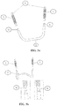
- FIG. 1 a is a front view of a versatile continuous loop exercise apparatus 10 in accordance with the present invention.
- FIG. 1 b is a side view of a continuous loop exercise apparatus 10 in accordance with the present invention.
- FIG. 1 c is an isometric view of a continuous loop exercise apparatus 10 in accordance with the present invention.
- FIG. 2 is an exploded isometric view of a continuous loop exercise apparatus 10 in accordance with the present invention.
- FIG. 3 a is front view of a continuous loop exercise apparatus 10 showing the assembly of female hole portion of the resistance elements and male spring-loaded connections of upper member in accordance with the present invention
- FIG. 3 b is an enlarged view of a continuous loop exercise apparatus 10 showing the assembly of female hole portion of the resistance elements and male spring-loaded 10 connections of the lower member 3 in accordance with the present invention
- FIG. 3 c is an enlarged view of a continuous loop exercise apparatus 10 showing the details of male spring-loaded connection 2 c of right member 2 and male spring-loaded connection 4 c of left member 4 , similarly, the details of male spring-loaded connection 3 c of the lower member 3 is shown in accordance with the present invention;
- FIG. 4 a is an isometric view of a continuous loop exercise apparatus 10 showing the resistance elements of varying sizes, according to another embodiment of the present invention
- FIG. 4 b is a side view of a continuous loop exercise apparatus 10 showing the resistance elements of varying sizes, according to another embodiment of the present invention.
- FIG. 5 a is an isometric view of a continuous loop exercise apparatus 10 showing some of the resistance elements being replaced with solid members, according to another embodiment of the present invention
- FIG. 5 b is a side view of a continuous loop exercise apparatus 10 showing some of the resistance elements being replaced with solid members, according to another embodiment of the present invention
- FIG. 6 a is an isometric view of a continuous loop exercise apparatus 10 showing the resistance elements being replaced with elastic members, according to another embodiment of the present invention
- FIG. 6 b is a side view of a continuous loop exercise apparatus 10 showing the resistance elements being replaced with elastic members, according to another embodiment of the present invention.
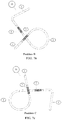
- FIG. 7 a is a side view of a continuous loop exercise apparatus 10 showing the exercise apparatus positioned in position A in accordance with one of the embodiments of the present invention
- FIG. 7 b is a side view of a continuous loop exercise apparatus 10 showing the exercise apparatus positioned in position B in accordance with one of the embodiments of the present invention
- FIG. 7 c is a side view of a continuous loop exercise apparatus 10 showing the exercise apparatus positioned in position C in accordance with one of the embodiments of the present invention
- FIG. 7 d is a side view of a continuous loop exercise apparatus 10 showing the exercise apparatus positioned in position D in accordance with one of the embodiments of the present invention
- FIG. 8 a is a side view of an assembled continuous loop exercise apparatus 10 shown as it could be used, in accordance with the present invention.
- FIG. 8 b is an isometric view of an assembled continuous loop exercise apparatus 10 shown as it could be used, in accordance with the present invention.
- FIG. 8 c is a side view of an assembled continuous loop exercise apparatus 10 shown as it could be used, in accordance with the present invention.
- the present invention is a versatile, multi-purpose and portable continuous loop exercise apparatus 10 that includes various components that are adjustable to support wide variety of exercises in a single apparatus.
- the present invention is a continuous loop exercise apparatus 10 as shown in FIG. 1 a , FIG. 1 b , and FIG. 1 c , comprising an upper member 1 , a right member 2 , a lower member 3 , a left member 4 and a plurality of resistance elements 5 , wherein each of the said members 1 , 2 , 3 and 4 , and resistance elements 5 further comprise a first end 1 a , 2 a , 3 a , 4 a and 5 a , and a second end 1 b , 2 b , 3 b , 4 b and 5 b , having mateable connections 1 c , 2 c , 3 c , 4 c and 5 c respectively.
- the said mateable connections 1 c , 2 c , 3 c , and 4 c , of the said upper member 1 , said right member 2 , said lower member 3 , and said left member 4 respectively according to an embodiment of the present invention, are male spring-loaded connections.
- the said mateable connection 5 c , of the said resistance elements 5 according to an embodiment of the present invention, is a female hole.
- the continuous loop exercise apparatus 10 as shown in FIG. 1 a , FIG. 1 b , and FIG. 1 c , includes an upper member 1 that provides support for the users to hold the exercise apparatus 10 .
- the continuous loop exercise apparatus 10 also includes a right member 2 and a left member 4 that form a loop structure which will support users to grip the continuous loop exercise apparatus 10 while performing exercises.
- the continuous loop exercise apparatus 10 further includes a lower member 3 which acts as a support structure for resting the continuous loop exercise apparatus 10 . Further, the continuous loop exercise apparatus 10 includes resistance elements 5 which are responsible for the flexion or extension of the continuous loop exercise apparatus 10 when all the components are assembled together.
- the mateable connections 1 c , 2 c , 3 c , and 4 c , of each of the said members 1 , 2 , 3 and 4 , respectively can be connected with the mateable connection 5 c of the resistance elements 5 , through snap-fit, screw-fitted, or any known means of attachment in the prior art.
- the said mateable connections of each of the said members can be connected through welding or any other techniques known to a person skilled in the art.
- the present invention is a uniquely designed continuous loop exercise apparatus 10 wherein, which in the assembled construction as shown in FIG. 1 a , FIG. 1 b , and FIG. 1 c , provides flexibility to perform various exercises without the requirement of any additional components or devices.
- the uniquely designed continuous loop exercise apparatus 10 can be placed in various positions on the floor, on the chair, or can be placed on a table or a countertop to perform various exercises. The simple assembling process enables the continuous loop exercise apparatus 10 to be quickly installed and carry out exercises to tone, tighten and strengthen the entire body.
- the lower member 3 is placed on the floor.
- One of the resistance elements 5 with a first end 5 a is placed over a first end of the lower member 3 a .
- another resistance element 5 with a first end 5 a is placed over a second end of the lower member 3 b .
- the left member 4 with a left member 4 a is placed over the second end 5 b of the said resistance element 5 .
- the right member 2 with a right member 2 a is placed over the second end 5 b of the said resistance element 5 .
- the apparatus is positioned to rest the right member 2 and the left member 4 on the floor.
- Another resistance element 5 with a first end 5 a is placed over a first end of the upper member 1 a and yet another resistance element 5 with a first end 5 a is placed over the second end of the upper member 1 b .
- the assembled component 1 along with the two resistance elements 5 with their second ends 5 b are placed over a second end of the right member 2 b and a second end of the left member 4 b respectively.
- the continuous loop exercise apparatus 10 is then brought back to the original position with the lower member 3 resting on the floor.
- Various assembly methods are known and can be used for assembling the present invention without limitation to the assembling approaches discussed here.
- FIG. 3 a , FIG. 3 b , and FIG. 3 c Further details of assembling the continuous loop exercise apparatus 10 is as shown in FIG. 3 a , FIG. 3 b , and FIG. 3 c , wherein the upper member 1 includes a first male spring-loaded connection 1 c on the first end 1 a and a second male spring-loaded connection 1 c on the second end 1 b .
- the right member 2 includes a first male spring-loaded connection 2 c on the first end 2 a and a second male spring-loaded connection 2 c on the second end 2 b .
- the lower member 3 includes a first male spring-loaded connection 3 c on the first end 3 a and a second male spring-loaded connection 3 c on the second end 3 b.
- the left member 4 includes a first male spring-loaded connection 4 c on the first end 4 a and a second male spring-loaded connection 4 c on the second end 4 b . Further each of the said resistance elements 5 includes a female hole 5 c on first end 5 a and another female hole 5 c on second end 5 b . As described, all the male spring-loaded connections are of the same construction and all the female holes are of the same size and shape to mate with the male connections.
- the continuous loop exercise apparatus 10 forms a unitary structure that would allow the user to perform various exercises by placing the continuous loop exercise apparatus 10 on the floor or on the chair or on the table or on the countertop.
- the alternative embodiments could include sets of resistance elements of differing lengths.
- the lower resistance elements 6 could be twice as long as the upper resistance elements 5 .
- the length of each of the four resistance elements could be increased or decreased based on the needs of the user. Such flexibility to increase or decrease the lengths of the members enables customization of the product to meet the requirements of consumers based on their size and exercise requirement.
- the present invention depicts four resistance elements 5 , in which a set of two resistance elements 5 could be replaced with standalone solid members 7 .
- the potential benefits of substituting the upper or lower resistance elements with solid members include increased stability for particular exercises, and easier to focus on a particular exercise without the incidence of any unanticipated movement.
- the lower resistance elements 5 are replaced with solid members 7 .
- the upper resistance elements 5 can also be replaced with solid members 7 keeping the lower resistance elements 5 unaltered.
- the resistance elements 5 may be substituted by elastic members 8 as shown in FIG. 6 a , and FIG. 6 b .
- the elastic members 8 could be but are not limited to springs, bands, cords and thereof. These members provide restorative force during exercise.
- the elastic members 8 could be constructed from materials including, but not limited to rubber, TPE, and woven fabric (bungie cord). Benefits to this embodiment may include lower manufacturing costs, lower pinch hazard, less shipping weight, and easier assemblage.
- the continuous loop exercise apparatus 10 can be positioned according to the type of exercise that would be performed when the apparatus is placed in a desired position. Some of the positions of the continuous loop exercise apparatus 10 are discussed in detail for reference and are not limited to the embodiments presented herewith.
- the lower member 3 in a first position, Position A, as shown in FIG. 7 a , the lower member 3 is placed on the floor or chair, or on a table or a countertop, wherein the loop structures 2 and 4 are positioned closer to the user and the upper member 1 is farther away from the user.
- the loop structures 2 and 4 can be flexed inwards or outwards, or pulled downwards or pushed upwards to perform certain types of exercises.
- the upper member 1 can be pushed downwards or pulled upwards.
- Position 5 B in another position, Position 5 B, as shown in FIG. 7 b , the upper member 1 and the loop structures 2 and 4 are placed on the floor or chair or on a table or on a countertop wherein, the lower member 3 is on the top facing upwards. In this position, the lower member 3 can be pulled downwards or pushed upwards to perform certain types of exercises. Similarly, the loop structures 2 and 4 can be flexed inwards and outwards, or pulled upwards or pushed downwards.
- Position C in yet another position, as shown in FIG. 7 c , the lower member 3 , and the loop structures 2 and 4 are placed on the floor or chair or on a table or a countertop, wherein the upper member 1 is on the top and facing upwards.
- the upper member 1 can be pulled inwards or pushed outwards to perform certain types of exercises.
- the loop structures 2 and 4 can be flexed inward or outward, or pushed upwards or pulled downwards.
- Position D in still another position, Position D, as shown in FIG. 7 d , the upper member 1 and the lower member 3 are placed on the floor or chair or on a table or a countertop, wherein the loop structures 2 and 4 are on the top and facing upwards.
- the loop structures 2 and 4 can be flexed inwards and outwards, or pulled downwards or pushed upwards to perform certain types of exercises.
- the continuous loop exercise apparatus 10 can be placed on the floor or a chair or a table or a countertop, however, these figures are for illustration purpose only.
- the members that are resting on the floor or the chair or the table or the countertop act as supporting structures to allow users to access the members that are not placed on the floor or 10 the chair or the table or the countertop.
- the user can direct force into the members at user selective locations for altering the torque directed into select resistance elements and altering restorative resistance relative to the user.
- the resistance elements could be of varying resistance possessing different resistance characteristics in order to adapt to users need and preferences.
Landscapes
- Health & Medical Sciences (AREA)
- General Health & Medical Sciences (AREA)
- Physical Education & Sports Medicine (AREA)
- Life Sciences & Earth Sciences (AREA)
- Biophysics (AREA)
- Orthopedic Medicine & Surgery (AREA)
- Rehabilitation Tools (AREA)
Abstract
Description
Claims (17)
Priority Applications (1)
| Application Number | Priority Date | Filing Date | Title |
|---|---|---|---|
| US15/733,819 US11117009B2 (en) | 2018-06-04 | 2019-06-01 | Continuous loop exercise apparatus and method |
Applications Claiming Priority (3)
| Application Number | Priority Date | Filing Date | Title |
|---|---|---|---|
| US201862680065P | 2018-06-04 | 2018-06-04 | |
| PCT/US2019/035089 WO2019236431A1 (en) | 2018-06-04 | 2019-06-01 | Continuous loop exercise apparatus and method |
| US15/733,819 US11117009B2 (en) | 2018-06-04 | 2019-06-01 | Continuous loop exercise apparatus and method |
Publications (2)
| Publication Number | Publication Date |
|---|---|
| US20210213320A1 US20210213320A1 (en) | 2021-07-15 |
| US11117009B2 true US11117009B2 (en) | 2021-09-14 |
Family
ID=68769204
Family Applications (1)
| Application Number | Title | Priority Date | Filing Date |
|---|---|---|---|
| US15/733,819 Expired - Fee Related US11117009B2 (en) | 2018-06-04 | 2019-06-01 | Continuous loop exercise apparatus and method |
Country Status (2)
| Country | Link |
|---|---|
| US (1) | US11117009B2 (en) |
| WO (1) | WO2019236431A1 (en) |
Families Citing this family (2)
| Publication number | Priority date | Publication date | Assignee | Title |
|---|---|---|---|---|
| US20220062019A1 (en) * | 2020-08-25 | 2022-03-03 | Ji Xiao | Wearable Device for Posture Correction and Muscle Training |
| WO2023139497A1 (en) * | 2022-01-18 | 2023-07-27 | Gitelmaker Michael | An exercising device and extensions thereof |
Citations (11)
| Publication number | Priority date | Publication date | Assignee | Title |
|---|---|---|---|---|
| US2223309A (en) | 1940-04-03 | 1940-11-26 | Swanson John | Exercising device |
| US3640529A (en) | 1970-06-22 | 1972-02-08 | John F Kane | Push-pull spring-type exercising device |
| US3985354A (en) | 1975-05-21 | 1976-10-12 | William Schulkin | Exercise device with spring biased telescoping members |
| USD322827S (en) | 1990-02-02 | 1991-12-31 | V-Partners Ltd. | Hand exerciser or similar article |
| USD343882S (en) | 1991-12-30 | 1994-02-01 | V-Partners, Ltd. | Physical exerciser |
| US5399138A (en) | 1993-02-16 | 1995-03-21 | Jones; Deanna L. | Portable exercise device |
| US6120424A (en) | 1997-08-22 | 2000-09-19 | Arline; Clayton | Body building apparatus |
| US6616580B1 (en) | 2000-08-30 | 2003-09-09 | Ko-Chuan Chen | Collapsible combination waist and leg exerciser |
| US20040110610A1 (en) | 2002-04-12 | 2004-06-10 | Ko-Chuan Chen | Rehabilitation equipment |
| US6966871B2 (en) | 2002-03-14 | 2005-11-22 | Parmater Productions Inc. | Multifunction exercise device |
| US8790227B2 (en) | 2011-06-10 | 2014-07-29 | Meister Management, Inc. | Exercise apparatus and methods |
-
2019
- 2019-06-01 US US15/733,819 patent/US11117009B2/en not_active Expired - Fee Related
- 2019-06-01 WO PCT/US2019/035089 patent/WO2019236431A1/en not_active Ceased
Patent Citations (11)
| Publication number | Priority date | Publication date | Assignee | Title |
|---|---|---|---|---|
| US2223309A (en) | 1940-04-03 | 1940-11-26 | Swanson John | Exercising device |
| US3640529A (en) | 1970-06-22 | 1972-02-08 | John F Kane | Push-pull spring-type exercising device |
| US3985354A (en) | 1975-05-21 | 1976-10-12 | William Schulkin | Exercise device with spring biased telescoping members |
| USD322827S (en) | 1990-02-02 | 1991-12-31 | V-Partners Ltd. | Hand exerciser or similar article |
| USD343882S (en) | 1991-12-30 | 1994-02-01 | V-Partners, Ltd. | Physical exerciser |
| US5399138A (en) | 1993-02-16 | 1995-03-21 | Jones; Deanna L. | Portable exercise device |
| US6120424A (en) | 1997-08-22 | 2000-09-19 | Arline; Clayton | Body building apparatus |
| US6616580B1 (en) | 2000-08-30 | 2003-09-09 | Ko-Chuan Chen | Collapsible combination waist and leg exerciser |
| US6966871B2 (en) | 2002-03-14 | 2005-11-22 | Parmater Productions Inc. | Multifunction exercise device |
| US20040110610A1 (en) | 2002-04-12 | 2004-06-10 | Ko-Chuan Chen | Rehabilitation equipment |
| US8790227B2 (en) | 2011-06-10 | 2014-07-29 | Meister Management, Inc. | Exercise apparatus and methods |
Also Published As
| Publication number | Publication date |
|---|---|
| WO2019236431A1 (en) | 2019-12-12 |
| US20210213320A1 (en) | 2021-07-15 |
Similar Documents
| Publication | Publication Date | Title |
|---|---|---|
| US11530777B2 (en) | Multi-use mounting bracket with extension and internal support rod for gym accessories | |
| US20130225372A1 (en) | Apparatus for Performing Body Exercises Having Pivotally Mounted Stabilizers | |
| US20190151699A1 (en) | Workout bench and handles with adjustable bands therebetween and methods of use thereof | |
| US9011296B2 (en) | Therapeutic exercise apparatus with multiple selectively interlockable sliding platforms | |
| JP4630877B2 (en) | Exercise system using exercise resistance cable | |
| US7922634B1 (en) | Pull exerciser | |
| US9259612B2 (en) | Exercise apparatus and methods | |
| US20110152046A1 (en) | Apparatus for Performing Body Exercises | |
| US20030216230A1 (en) | Multi-purpose exercise device with synchronized sliding | |
| US20050250628A1 (en) | Prone fly exercise apparatus | |
| US20170056708A1 (en) | Bridge bench | |
| US7736285B2 (en) | Portable exercise device | |
| US6872170B2 (en) | Multi-function physical training machine | |
| US9199121B2 (en) | Exercising device for lower-body | |
| US20040147380A1 (en) | Universal exercise article | |
| GB2277277A (en) | Multiple exercise apparatus | |
| US20140128231A1 (en) | Unique Exercise and Strength Training Apparatus, and Method of Exercise and Strength Training | |
| US9180338B2 (en) | Exercise device for push ups | |
| US12173843B2 (en) | Multi-use mounting bracket for gym accessories | |
| US9248332B2 (en) | Exercise apparatus, methods of using, and method of manufacture | |
| US20030224913A1 (en) | Multifunctional physical training machine | |
| US10773119B2 (en) | Exercise slider | |
| US11117009B2 (en) | Continuous loop exercise apparatus and method | |
| US6616580B1 (en) | Collapsible combination waist and leg exerciser | |
| US9211430B1 (en) | Exercise apparatus and method |
Legal Events
| Date | Code | Title | Description |
|---|---|---|---|
| FEPP | Fee payment procedure |
Free format text: ENTITY STATUS SET TO UNDISCOUNTED (ORIGINAL EVENT CODE: BIG.); ENTITY STATUS OF PATENT OWNER: SMALL ENTITY |
|
| FEPP | Fee payment procedure |
Free format text: ENTITY STATUS SET TO SMALL (ORIGINAL EVENT CODE: SMAL); ENTITY STATUS OF PATENT OWNER: SMALL ENTITY |
|
| STPP | Information on status: patent application and granting procedure in general |
Free format text: NOTICE OF ALLOWANCE MAILED -- APPLICATION RECEIVED IN OFFICE OF PUBLICATIONS |
|
| STPP | Information on status: patent application and granting procedure in general |
Free format text: PUBLICATIONS -- ISSUE FEE PAYMENT VERIFIED |
|
| STCF | Information on status: patent grant |
Free format text: PATENTED CASE |
|
| AS | Assignment |
Owner name: PARKER, DONALD, JAPAN Free format text: ASSIGNMENT OF ASSIGNORS INTEREST;ASSIGNORS:RENNECKER, DANIEL;SCHENNUM, STEVEN;MCKEON, THOMAS;AND OTHERS;REEL/FRAME:057368/0348 Effective date: 20210830 |
|
| FEPP | Fee payment procedure |
Free format text: MAINTENANCE FEE REMINDER MAILED (ORIGINAL EVENT CODE: REM.); ENTITY STATUS OF PATENT OWNER: SMALL ENTITY |
|
| LAPS | Lapse for failure to pay maintenance fees |
Free format text: PATENT EXPIRED FOR FAILURE TO PAY MAINTENANCE FEES (ORIGINAL EVENT CODE: EXP.); ENTITY STATUS OF PATENT OWNER: SMALL ENTITY |
|
| STCH | Information on status: patent discontinuation |
Free format text: PATENT EXPIRED DUE TO NONPAYMENT OF MAINTENANCE FEES UNDER 37 CFR 1.362 |
|
| FP | Lapsed due to failure to pay maintenance fee |
Effective date: 20250914 |