US11115563B2 - Method and apparatus for nonlinear interpolation color conversion using look up tables - Google Patents
Method and apparatus for nonlinear interpolation color conversion using look up tables Download PDFInfo
- Publication number
- US11115563B2 US11115563B2 US16/022,999 US201816022999A US11115563B2 US 11115563 B2 US11115563 B2 US 11115563B2 US 201816022999 A US201816022999 A US 201816022999A US 11115563 B2 US11115563 B2 US 11115563B2
- Authority
- US
- United States
- Prior art keywords
- color gamut
- linear interpolation
- target color
- sub
- pixels
- Prior art date
- Legal status (The legal status is an assumption and is not a legal conclusion. Google has not performed a legal analysis and makes no representation as to the accuracy of the status listed.)
- Active
Links
Images


Classifications
-
- H—ELECTRICITY
- H04—ELECTRIC COMMUNICATION TECHNIQUE
- H04N—PICTORIAL COMMUNICATION, e.g. TELEVISION
- H04N1/00—Scanning, transmission or reproduction of documents or the like, e.g. facsimile transmission; Details thereof
- H04N1/46—Colour picture communication systems
- H04N1/56—Processing of colour picture signals
- H04N1/60—Colour correction or control
- H04N1/6058—Reduction of colour to a range of reproducible colours, e.g. to ink- reproducible colour gamut
-
- H—ELECTRICITY
- H04—ELECTRIC COMMUNICATION TECHNIQUE
- H04N—PICTORIAL COMMUNICATION, e.g. TELEVISION
- H04N1/00—Scanning, transmission or reproduction of documents or the like, e.g. facsimile transmission; Details thereof
- H04N1/46—Colour picture communication systems
- H04N1/56—Processing of colour picture signals
- H04N1/60—Colour correction or control
- H04N1/6016—Conversion to subtractive colour signals
- H04N1/6019—Conversion to subtractive colour signals using look-up tables
-
- G—PHYSICS
- G06—COMPUTING; CALCULATING OR COUNTING
- G06T—IMAGE DATA PROCESSING OR GENERATION, IN GENERAL
- G06T1/00—General purpose image data processing
- G06T1/20—Processor architectures; Processor configuration, e.g. pipelining
-
- G—PHYSICS
- G06—COMPUTING; CALCULATING OR COUNTING
- G06T—IMAGE DATA PROCESSING OR GENERATION, IN GENERAL
- G06T3/00—Geometric image transformation in the plane of the image
- G06T3/40—Scaling the whole image or part thereof
- G06T3/4007—Interpolation-based scaling, e.g. bilinear interpolation
-
- G—PHYSICS
- G09—EDUCATION; CRYPTOGRAPHY; DISPLAY; ADVERTISING; SEALS
- G09G—ARRANGEMENTS OR CIRCUITS FOR CONTROL OF INDICATING DEVICES USING STATIC MEANS TO PRESENT VARIABLE INFORMATION
- G09G3/00—Control arrangements or circuits, of interest only in connection with visual indicators other than cathode-ray tubes
- G09G3/20—Control arrangements or circuits, of interest only in connection with visual indicators other than cathode-ray tubes for presentation of an assembly of a number of characters, e.g. a page, by composing the assembly by combination of individual elements arranged in a matrix no fixed position being assigned to or needed to be assigned to the individual characters or partial characters
- G09G3/2003—Display of colours
-
- H—ELECTRICITY
- H04—ELECTRIC COMMUNICATION TECHNIQUE
- H04N—PICTORIAL COMMUNICATION, e.g. TELEVISION
- H04N19/00—Methods or arrangements for coding, decoding, compressing or decompressing digital video signals
- H04N19/80—Details of filtering operations specially adapted for video compression, e.g. for pixel interpolation
-
- H—ELECTRICITY
- H04—ELECTRIC COMMUNICATION TECHNIQUE
- H04N—PICTORIAL COMMUNICATION, e.g. TELEVISION
- H04N23/00—Cameras or camera modules comprising electronic image sensors; Control thereof
- H04N23/70—Circuitry for compensating brightness variation in the scene
- H04N23/741—Circuitry for compensating brightness variation in the scene by increasing the dynamic range of the image compared to the dynamic range of the electronic image sensors
-
- H04N5/2355—
-
- G—PHYSICS
- G09—EDUCATION; CRYPTOGRAPHY; DISPLAY; ADVERTISING; SEALS
- G09G—ARRANGEMENTS OR CIRCUITS FOR CONTROL OF INDICATING DEVICES USING STATIC MEANS TO PRESENT VARIABLE INFORMATION
- G09G2320/00—Control of display operating conditions
- G09G2320/06—Adjustment of display parameters
- G09G2320/0666—Adjustment of display parameters for control of colour parameters, e.g. colour temperature
Definitions
- Recent improvements in monitors, television screens, and/or other display screens allow users to view movies and/or images in higher definition settings.
- some monitors and/or other display screens may only be able to show movies and images in a standard dynamic range (SDR)
- other monitors and/or other display screens may show movies and images in a high dynamic range (HDR) or a wide color gamut (WCG).
- higher definition settings such as settings with high luminance levels and/or very wide color gamuts (e.g., HDR or WCG), may require additional resources and/or processing to display on a device with a limited luminance range and/or narrower color gamut.
- HDR movies and images may have a dynamic luminance range of 0 to 10,000 nits.
- SDR displays may only have a dynamic luminance of 0.1 to 100 nits.
- some monitors and/or other display screens might not have the capability to display HDR movies and/or images while maintaining reasonable picture quality.
- Image processors such as graphics processing units (GPUs), central processing units (CPUs), application-specific integrated circuits (ASICs), and other processors, may use look-up tables (LUTs) to allow HDR movies and/or images to be shown on SDR display screens.
- LUTs look-up tables
- an HDR display screen may be able to display a color gamut that includes one hundred different shades of red
- an SDR display screen may be able to display a color gamut that includes only sixty of the hundred shades of red.
- graphics processing units may use LUTs to map each of the hundred different shades of red to one of the sixty shades of red.
- FIG. 1 is a schematic block diagram illustrating an apparatus for mapping between color gamuts in accordance with one embodiment set forth in the disclosure
- FIG. 2 is a schematic block diagram illustrating an example of a non-linear interpolation color conversion logic for mapping between different color gamuts in accordance with one embodiment set forth in the disclosure
- FIG. 3 is a flowchart illustrating a method for mapping between color gamuts in accordance with one embodiment set forth in the disclosure
- FIG. 4 is a schematic block diagram illustrating another example of an apparatus for mapping between different color gamuts in accordance with one embodiment set forth in the disclosure
- FIG. 5 is a schematic block diagram illustrating a graphics processing unit for mapping between different color gamuts in accordance with one embodiment set forth in the disclosure
- FIG. 6 is an exemplary pictorial representation of a red green blue (RGB) color space for a color gamut in accordance with one embodiment set forth in the disclosure
- FIG. 7 is an exemplary pictorial representation of vertices of a sub-cube in accordance with one embodiment set forth in the disclosure.
- FIG. 8 is an exemplary pictorial representation of a non-linearized pixel within a sub-cube in accordance with one embodiment set forth in the disclosure.
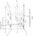
- FIG. 9 is an exemplary pictorial representation of a linearized pixel within a sub-cube in accordance with one embodiment set forth in the disclosure.
- an apparatus provides a method for converting between color gamuts using interpolation of a plurality of pixel values from a reduced 3-D look-up table (LUT). Additionally, the apparatus provides a method to minimize the interpolation error using the reduced 3-D LUT.
- Gamut mapping describes mapping or converting pixels from one color gamut, such as a source (e.g., High Dynamic Range [HDR] or wide color gamut [WCG]) color gamut, to another color gamut that is more limited, such as a target (e.g., Standard Dynamic Range [SDR]) color gamut.
- HDR High Dynamic Range
- WCG wide color gamut
- the method and apparatus obtains a source image, such as a video frame, movie frame, or an image.
- the source image is in a color gamut that cannot be entirely displayed by a display device due to a difference in color gamuts between the source image and the displayable color gamut of the display system.
- the source image is in a HDR color gamut whereas the display device can only display SDR color gamuts.
- the method and apparatus obtains a reduced 3-D LUT for a color gamut, such as a target color gamut.
- the method and apparatus converts source color gamut pixels from the source image to target color gamut pixels that are able to be displayed on the target display device using the reduced 3-D LUT for the target color gamut while maintaining good picture quality.
- the method and apparatus determines a sub-cube representing entries (e.g., vertices, displayable pixel values, or displayable target color values) within the reduced 3-D LUT.
- the method and apparatus determines a set of coefficients for the sub-cube, and uses the set of coefficients to transform the source color gamut pixels.
- the method and apparatus performs interpolation (e.g., tetrahedral, tri-linear, or non-linear) on the transformed pixel values to convert them to target color gamut pixels.
- the method and apparatus obtains a source image having a plurality of source color gamut pixels in a source color gamut.
- the method and apparatus converts the plurality of source color gamut pixels to a plurality of corresponding target color gamut pixels using non-linear interpolation of a plurality of output pixel values from a reduced 3-D look-up table (LUT) for a target color gamut.
- the method and apparatus provides, for display, the plurality of target color gamut pixels (e.g., one or more pixels) on a target color gamut display.
- the method and apparatus performs a non-linear interpolation for a plurality of first pixel values from the reduced 3-D LUT that is different from a second non-linear interpolation for a plurality of second pixel values from the reduced 3-D LUT.
- the plurality of first pixel values from the reduced 3-D LUT represent vertices of a sub-cube within the target color gamut.
- the plurality of second pixel values from the reduced 3-D LUT represent vertices of a different sub-cube within the target color gamut.
- the method and apparatus determines a set of polynomial coefficients for the sub-cube based on the first plurality of source color gamut pixel values.
- the method and apparatus performs the first non-linear interpolation based on the set of polynomial coefficients.
- the method and apparatus converts pixel values of the pixel, from the plurality of source color gamut pixels, to transformed pixel values based on the set of polynomial coefficients for the selected sub-cube.
- a graphics driver calculates the set of polynomial coefficients by performing a Taylor Series transform based on the non-linear interpolation of the vertices of the sub-cube within the target color gamut.
- the first non-linear interpolation is a piecewise linear curve or a polynomial equation.
- the method and apparatus converts the plurality of source color gamut pixels to the plurality of corresponding target color gamut pixels using a 3-D engine. In some examples, the method and apparatus converts the plurality of source color gamut pixels to the plurality of corresponding target color gamut pixels using a video encoder before encoding video in target color gamut. The video encoder obtains the plurality of source color gamut pixels from a server via an internet connection. In some implementations, the method and apparatus converts the plurality of source color gamut pixels to the plurality of corresponding target color gamut pixels using a display engine. The display engine performs tone mapping operations for the target color gamut display.
- FIG. 1 illustrates one example of an apparatus 100 , such as an image processing device, for non-linear interpolation color conversion logic.
- the apparatus 100 includes any type of computing device suitable for implementing aspects of embodiments of the disclosed subject matter. Examples of computing devices include but are not limited to “workstations,” “servers,” “cloud computing platforms”, “laptops,” “desktops,” “tablet computers,” “hand-held devices,” “game consoles,” “general-purpose graphics processing units (GPGPUs),” “APUs,” “CPUs,” “GPUs,” “state machines,” printers, integrated circuits and the like, all of which are contemplated within the scope of FIG. 1 , with reference to various components of the apparatus 100 .
- GPUs general-purpose graphics processing units
- the apparatus 100 includes non-linear interpolation color conversion logic 120 and display device(s) 140 .
- the non-linear interpolation color conversion logic 120 obtains source color gamut pixels 110 and reduced 3-D look up tables (LUTs) for a target color gamut.
- FIG. 2 illustrates an example of the non-linear interpolation color conversion logic 120 .
- the non-linear interpolation color conversion logic 120 includes a shaper LUT unit 202 , a reduced 3-D LUT unit 204 , interpolation logic unit 206 , polynomial coefficient selection unit 208 , a multiplexer 210 , a coefficient set unit 212 , and a polynomial algorithm unit 214 .
- these sub-units 202 , 204 , 206 , 208 , 210 , 212 , and 214 are illustrated as children units subordinate of the parent unit, each sub-unit can be operated as a separate unit from the non-linear interpolation color conversion logic 120 , and other suitable combinations of sub-units are contemplated to suit different applications.
- the non-linear interpolation color conversion logic 120 is any suitable logic configuration including, but not limited to, one or more state machines, one or more digital signal processors, GPUs, APUs or processors that execute kernels, and/or other suitable structure as desired. Further, as described in further detail below in FIG. 3 , the non-linear interpolation color conversion logic 120 converts the source color gamut pixels 110 to corresponding target color gamut pixels 130 .
- the apparatus 100 optionally includes display device(s) 140 .
- the non-linear interpolation color conversion logic 120 and the display device(s) 140 are in the same apparatus.
- the display device 140 includes one or more monitors, television screens, projection device, and/or other display screens that display and/or show video frames, movies, and/or images.
- the display device 140 obtains, from the non-linear interpolation color conversion logic 120 , pixels (e.g., target color gamut pixels 130 ) and/or displays the target color gamut pixels 130 .
- some apparatuses 100 such as cloud computing platforms, servers, and/or integrated circuits, may not include a display device.
- the non-linear interpolation color conversion logic 120 uses the reduced 3-D LUTs for the target color gamut of the display device to convert from source color gamut pixels 110 to target color gamut pixels 130 . After converting the pixels from the source to target color gamut, the non-linear interpolation color conversion logic 120 transmits and/or sends image data via the internet, wirelessly via wired buses, or through any suitable manner to one or more additional apparatuses that house the display device(s) 140 .
- the illustrative apparatus 100 including the non-linear interpolation color conversion logic 120 , shown in FIGS. 1 and 2 , are not intended to suggest any limitation as to the scope of use or functionality of embodiments of the present disclosure. Neither should the illustrative apparatus 100 or the non-linear interpolation color conversion logic 120 be interpreted as having any dependency or requirement related to any single component or combination of components illustrated therein. Additionally, various components depicted in FIGS. 1 and 2 are, in embodiments, integrated with various ones of the other components depicted therein (and/or components not illustrated), all of which are considered to be within the ambit of the present disclosure.
- FIG. 3 illustrates one example of a method for non-linear interpolation color conversion.
- FIG. 3 is described below in reference to the apparatus 100 illustrated in FIG. 1 and the non-linear interpolation color conversion logic 120 illustrated in FIG. 3 .
- any suitable structure can be employed.
- the non-linear interpolation color conversion logic 120 illustrated in FIG. 2 is described with reference to the method in FIG. 3 .
- the non-linear interpolation color conversion logic 120 includes additional units than those illustrated in FIG. 2 .
- one or more sub-units 202 , 204 , 206 , 208 , 210 , 212 , or 214 are missing from the non-linear interpolation color conversion logic 120 .
- the non-linear interpolation color conversion logic 120 obtains (e.g., receives and/or retrieves) a source image having a plurality of source color gamut pixels 110 in a source color gamut.
- obtaining the source image includes, but is not limited to receiving the source frame(s) from a source image provider and/or retrieving the source image from one or more frame buffers in memory, a server, and/or other source.
- the source image is from a video (e.g., a video frame), video and/or computer game, and/or another suitable image.
- the source image is composed of pixels, such as source color gamut pixels 110 .
- the source color gamut pixels 110 are encoded for a source color gamut, such as an HDR or WCG color gamut (e.g., a BT.2020 color gamut, BT.2100 color gamut, DCI-P3 color gamut, P3 color gamut).
- a source color gamut such as an HDR or WCG color gamut (e.g., a BT.2020 color gamut, BT.2100 color gamut, DCI-P3 color gamut, P3 color gamut).
- the source color gamut includes one hundred different shades of red.
- the display device 140 has a target (e.g., more limited) color gamut, such as SDR color gamut (e.g., Rec.709 color gamut, Adobe RGB 1998 color gamut, BT 709 color gamut, sRGB color gamut, or additional color gamuts that are smaller and/or narrower than the BT. 709 color gamut).
- SDR color gamut e.g., Rec.709 color gamut, Adobe RGB 1998 color gamut, BT 709 color gamut, sRGB color gamut, or additional color gamuts that are smaller and/or narrower than the BT. 709 color gamut.
- the target color gamut includes sixty shades of red. Due to the limited color gamut display capabilities, the display device 140 is not able to reproduce and display or show the source color gamut pixels 110 in the HDR color gamut (e.g., all one hundred shades of red).
- the non-linear interpolation color conversion logic 120 converts the plurality of source color gamut pixels 110 to a plurality of corresponding target color gamut pixels 130 using non-linear interpolation of a plurality of output pixel values from a reduced 3-D look-up table (LUT) corresponding to a target color gamut.
- converting the plurality of source color gamut pixels 110 to a plurality of target color gamut pixels 130 includes, but is not limited to, transforming and/or mapping the plurality of source color gamut pixels 110 to a plurality of target color gamut pixels 130 .
- Step 304 can be performed using many different implementations. FIG. 3 describes one such implementation of step 304 .
- the shaper LUT unit 202 is optional. Instead, the polynomial coefficient selection unit 208 , the polynomial algorithm unit 214 , and/or the reduced 3-D LUT unit 204 can obtain the source color gamut pixels 110 directly via an internet connection and/or from memory 440 .
- the reduced 3-D LUT unit 204 obtains data 220 , such as the source color gamut pixels 110 . Further, the reduced 3-D LUT unit 204 obtains LUTs, such as reduced 3-D LUTs 115 for the target color gamut.
- LUTs include entries for pixel values. For example, each entry corresponds to a RGB pixel value for a color gamut, such as a target color gamut. In other words, each entry is a displayable target color value for the display device 140 . In some embodiments, the entries within a reduced 3-D LUT are not displayable target colors for the display device 140 .
- the entries of the reduced LUT are in another color format, such as the best color format to reduce the interpolation error. Then, the output is then further converted to other color formats using another reduced 3-D LUT and/or another method. After the second, third, or subsequent conversions, the display device 140 is able to display the result.
- the reduced 3-D LUT 115 includes less than all the entries within the color gamut.
- an example color gamut such as the target or source color gamut, can include numerous different colors.
- a 3-dimensional (3-D) color space e.g., red, green, blue color space
- each RGB value being 8 bits long
- the color gamut can represent 2 ⁇ circumflex over ( ) ⁇ 24 or 16,777,216 different colors.
- An N-dimensional color space e.g., red, green, blue, and/or other colors in a color space
- a 1 to 1 mapping of source to target color gamuts in just the 3-D space (e.g., a 1 to 1 conversion ratio from source to target color gamuts) includes 16,777,216 different entries.
- the reduced 3-D LUT 115 includes less than 16,777,216 different entries.
- the reduced 3-D LUT 115 includes 3 values for red, 3 values for green, and 3 values for blue for a total of 27 entries.
- the reduced 3-D LUT can include any number of entries, including more or less than 27 entries.
- the reduced 3-D LUT can include 17 values for red, green, and blue for a total of 4096 entries.
- the reduced 3-D LUT might not be in 3-D, but rather an LUT that includes N-dimensions (N-D).
- the reduced LUT (e.g., 3-D or N-D) includes RGB values that are M number of bits long (e.g., 8, 10, 12, or 14 bits). All different variations of the reduced 3-D LUT 115 , including any number of entries within the reduced 3-D LUT 115 , are included within the method described within.
- FIG. 6 shows a graphical example of an RGB color space for a color gamut (e.g., the target color gamut).
- the reduced 3-D LUT 115 includes RGB color value entries and by mapping the entries into xyz coordinates (e.g., x axis represents red values 605 ; the z axis represents green values 610 ; and the y axis represents blue values 615 ), an example RGB color space is illustrated.
- the color space for the target color gamut is encompassed and/or represented by a cube 600 .
- the cube 600 also includes polygons or sub-cubes, such as sub-cubes 620 and 625 .
- the entries of the reduced 3-D LUTs 115 are vertices (e.g., pixel values) of the plurality of sub-cubes.
- cubes e.g., cube 600
- sub-cubes e.g., sub-cube 620 and 625
- the cubes and/or sub-cubes can have more or less than 6 faces.
- the cube 600 and/or sub-cubes can any suitable volume, including but not limited to hexahedrons, cylinders, spheres, and/or other 2-D and/or 3-D polygons. While FIG. 6 shows the RGB color space, in some implementations, the non-linear interpolation can be applied to other color spaces, such as YCbCr or ICrCp.
- FIG. 7 shows a graphical example of the vertices of one sub-cube, such as sub-cube 620 .
- each of the vertices denoted by points 701 - 708 , are entries within the reduced 3-D LUT 115 .
- point 701 represents the first entry in the reduced 3-D LUT 115
- point 702 represents the second entry, and so on.
- the reduced 3-D LUT unit 204 identifies, on a pixel-by-pixel basis, a sub-cube for a pixel from the source color gamut pixels 110 . For example, referring to FIG. 7 , the reduced 3-D LUT unit 204 identifies sub-cube 620 within cube 600 if the RGB pixel values are within the RGB values of the vertices. In other words, the reduced 3-D LUT unit 204 identifies the sub-cube as the sub-cube with vertices (e.g., RGB values from the reduced 3-D LUT 115 ) surrounding the pixel (e.g., the pixel value).
- vertices e.g., RGB values from the reduced 3-D LUT 115
- the sub-cube (e.g., sub-cube 620 ) is able to be identified based on the most significant bits from the pixel value for the pixel. For instance, if each RGB value has 14 bits, then the four most significant bits (e.g., the four largest bits for each of the RGB values) are used to determine the sub-cube. Thus, in such implementations, data 220 can include the four largest bits of the RGB values.
- the reduced 3-D LUT unit 204 transmits data 222 , such as the 3D LUT content corresponding to vertices of the sub-cube, to the interpolation logic unit 206 .
- the interpolation logic unit 206 uses the data 222 to convert the pixel from the plurality of source color gamut pixels 110 to a corresponding pixel of the target color gamut pixels 130 .
- the interpolation logic unit 206 performs a tri-linear interpolation or a tetrahedral interpolation using the vertices of the sub-cube to convert the pixel from the source color gamut pixels 110 to the target color gamut pixels 130 .
- converting a pixel value from the source color gamut to the target color gamut requires a non-linear transform, equation, and/or conversion.
- tri-linear and/or tetrahedral interpolation uses only linear equations to convert the pixel values from source to target color gamuts.
- a shaper LUT unit 202 obtains source color gamut pixels 110 .
- each of the pixels 110 contains pixel values (e.g., red, green, blue values).
- the shaper LUT unit 202 converts the pixel color values to a new set of pixel values.
- the shaper LUT unit 202 performs a non-linear transform function on the pixel values of the source color gamut pixels 110 to generate a new set of pixel values.
- the shaper LUT unit 202 transmits the new set of pixel values to the reduced 3-D LUT unit 204 and the polynomial coefficient selection unit 208 .
- the shaper LUT unit 202 transmits the new set of pixel values (e.g., the input pixel values) to the reduced 3-D LUT unit 204 .
- the shaper LUT unit 202 does not perform non-linear interpolation of the output values (e.g., output pixel values) from the reduced 3-D LUT unit 204 .
- the shaper LUT unit 202 obtains a shaper LUT 216 .
- the shaper LUT is a look up table that transforms the pixel values of the source color gamut pixels 110 to the new set of pixel values.
- non-linearity between different sub-cubes e.g., sub-cubes 620 and 625
- a color gamut e.g., cube 600
- some sub-cubes are linear and/or almost linear (e.g., the center sub-cubes of cube 600 )
- other sub-cubes are slightly non-linear
- even other sub-cubes are significantly non-linear (e.g., the surface sub-cubes, such as sub-cube 620 ).
- the interpolation logic unit 206 obtains and/or uses data 234 , such as RGB values, from the polynomial algorithm unit 214 .
- the non-linear interpolation color conversion logic 120 uses the non-linearity within a sub-cube (e.g., sub-cube 620 ) to convert from the plurality of source color gamut pixels 110 to the plurality of target color gamut pixels 130 . This is described in further detail below within reference to the polynomial coefficient selection unit 208 , the multiplexer 210 , the coefficient set unit 212 , and the polynomial algorithm unit 214 .
- the polynomial coefficient selection unit 208 obtains data 224 , such as the source color gamut pixels 110 , from the shaper LUT unit 202 . Similar to the reduced 3-D LUT unit 204 , the polynomial coefficient selection unit 208 identifies, on a pixel-by-pixel basis, a sub-cube for a pixel from the source color gamut pixels 110 . For example, referring to FIG. 7 , the polynomial coefficient selection unit 208 identifies sub-cube 620 within cube 600 if the RGB pixel values are within the RGB values of the vertices (e.g., between [0,0,0] and [0.5333,0.5333,0.5333]).
- the polynomial coefficient selection unit 208 identifies the sub-cube as the sub-cube with vertices (e.g., RGB values from the reduced 3-D LUT 115 ) surrounding the pixel (e.g., the pixel value).
- the sub-cube e.g., sub-cube 620
- the sub-cube is able to be identified based on the most significant bits for the pixel. For instance, if each RGB value has 14 bits, then the four most significant bits (e.g., the four largest bits for each of the RGB values) are used to determine the sub-cube.
- data 224 includes the four most significant bits of the pixel.
- the polynomial coefficient selection unit 208 After identifying the sub-cube for the pixel from the source color gamut pixels 110 , the polynomial coefficient selection unit 208 obtains, from memory (e.g., read only memory [ROM] or read access memory [RAM]), a coefficient select value 236 .
- memory e.g., read only memory [ROM] or read access memory [RAM]
- each sub-cube within cube 600 is stored as a different coefficient select value.
- sub-cube 620 has a coefficient select value of 1
- sub-cube 625 has a coefficient select value of 2.
- Each of the 8 sub-cubes in FIG. 6 has a different coefficient select value.
- the polynomial coefficient selection unit 208 obtains a coefficient select value from 1 to 4096.
- the polynomial coefficient selection unit 208 transmits data 226 , such as the coefficient select value, to the multiplexer 210 . Additionally, the multiplexer 210 also obtains data 228 , such as a plurality of coefficient sets, from the coefficient set unit 212 . Each coefficient select value is for a corresponding sub-cube from cube 600 , and depending on the sub-cube, the multiplexer 210 selects a set of coefficients. For example, the coefficient select value 226 is the control signal, the multiplexer 210 selects a set of coefficients from the plurality of coefficient sets 228 .
- the coefficient set unit 212 obtains, stores, and/or calculates a coefficient set for one or more sub-cubes. For example, in some implementations, the coefficient set unit 212 obtains, stores, and/or calculates a different coefficient set for each sub-cube (e.g., sub-cubes 1 - 8 shown in FIG. 6 ). In other implementations, the coefficient set unit 212 obtains, stores, and/or calculates a same coefficient set for one or more sub-cubes (e.g., for sub-cube 620 and 625 ).
- the coefficient set unit 212 calculates the coefficient sets based on the nonlinearity of the red, green, and blue color mapping values for a corresponding sub-cube. For example, the coefficient set unit 212 calculates a coefficient set based on the RGB values within the sub-cube. In some variations, the coefficient set unit 212 calculates a Taylor Series polynomial from the non-linearity of the sub-cube (e.g., sub-cube 620 ). The coefficients of the Taylor Series are the set of coefficients for the sub-cube (e.g., sub-cube 620 ). In some embodiments, the coefficient set unit 212 calculates the set of coefficients for the sub-cube using a piece-wise linear function of a 1D LUT.
- the coefficient set unit 212 calculates a different coefficient set for each sub-cube. In other implementations, such as implementations with similar linearity between sub-cubes, the coefficient set unit 212 calculates a single set of coefficients for a set of sub-cubes with similar linearity. By doing so, the design costs are minimized. Further, in even other implementations, the coefficient set unit 212 calculates a linear coefficient set for a sub-cube (e.g., center sub-cubes with linear properties).
- the coefficient set unit 212 obtains and/or stores the coefficient set for the one or more sub-cubes.
- the apparatus 100 includes a graphics driver.
- the graphics driver is within a processor, such as a central processing unit (CPU) or an accelerated processing unit (APU).
- the graphics driver calculates the set of coefficients for the one or more sub-cubes and then transmits the set of coefficients 218 to the coefficient set unit 212 .
- the coefficient set unit 212 then stores the set of coefficients 218 .
- the graphics driver may calculate the set of coefficients prior to the coefficient set unit 212 using the set of coefficients.
- the multiplexer 210 selects a set of coefficients from the coefficient set unit 212 . After selecting the set of coefficients, the multiplexer 210 transmits data 230 , such as the set of selected coefficients, to the polynomial algorithm unit 214 .
- the polynomial algorithm unit 214 uses the set of selected coefficients to linearize the RGB values for the source color gamut pixels 110 . For example, the polynomial algorithm unit 214 obtains, from the shaper LUT unit 202 and/or directly, data 232 , such as the source color gamut pixels 110 .
- the polynomial algorithm unit 214 obtains the set of selected coefficients 230 from the multiplexer 210 and uses the set of coefficients for the multiplexer to linearize and/or transform the RGB values for the pixel of the plurality of source color gamut pixels 110 . Afterwards, the polynomial algorithm unit 214 transmits data 234 , such as the linearized RGB values for the pixel, to the interpolation logic unit 206 .
- the polynomial algorithm unit 214 uses a non-linear function (e.g., a piecewise curve and/or a polynomial equation) to transform the RGB values.
- the non-linear function includes coefficients for the sub-cube that the pixel is surrounded by, such as sub-cube 620 .
- the polynomial algorithm unit 214 uses non-linear interpolation of a plurality of output pixel values (e.g., vertices of a sub-cube) to linearize the RGB values.
- the polynomial algorithm unit 214 uses a different non-linear function (e.g., a piecewise curve and/or a polynomial equation) for one or more sub-cubes. For example, the polynomial algorithm unit 214 obtains the coefficient selection value identifying the sub-cube for the pixel. Depending on the coefficient selection value, the polynomial algorithm unit 214 selects a non-linear function for the sub-cube. In some examples, the selected non-linear function is different for each sub-cube. In other examples, the selected non-linear function is the same for one or more sub-cubes.
- a different non-linear function e.g., a piecewise curve and/or a polynomial equation
- the interpolation logic unit 206 obtains the data 234 , such as the transformed RGB values for the sub-cube, and uses an interpolation (e.g., tetrahedral or tri-linear interpolation or other non-linear interpolation techniques) to convert from the transformed RGB values to a corresponding pixel from the plurality of target color gamut pixels 130 .
- the non-linear interpolation in unit 206 can be implemented using polynomial functions for each R, G and B or other more complex non-linear functions that involves R, G and B values simultaneously.
- the polynomial algorithm unit 214 and/or the interpolation logic unit 206 uses the output values (e.g., output pixel values) from the reduced 3-D LUT unit 204 to perform non-linear interpolation to minimize the errors during conversion from the plurality of source gamut pixels to the plurality of target color gamut pixels.
- FIGS. 8 and 9 illustrate an example of performing interpolation for a pixel from the source color gamut pixels 110 that is within a sub-cube, such as sub-cube 620 .
- the interpolation logic unit 206 obtains a pixel 810 from the plurality of source color gamut pixels 110 with a pixel value of [0.2667, 0.2667, 0.2667].
- the pixel 810 is not linearized for the vertices within the sub-cube 620 (e.g., the polynomial coefficient selection unit 208 , multiplexer 210 , coefficient set unit 212 , and/or the polynomial algorithm unit 214 are not used to linearize the pixel 810 ).
- the shaper LUT unit 202 is used to linearize the pixel value for pixel 810 .
- the pixel value for the pixel 810 (e.g., the corresponding target color gamut pixel 130 ) is [0.1106, 0.1106, 0.1106].
- the correct value for the pixel is [0.0419, 0.0419, 0.0419].
- the interpolation logic unit 206 linearizes pixel 810 using vertices within the sub-cube 620 (e.g., the polynomial coefficient selection unit 208 , multiplexer 210 , coefficient set unit 212 , and/or the polynomial algorithm unit 214 are used to linearize the pixel 810 ) to create or generate pixel 910 .
- the pixel 910 After linearizing the pixel 810 using the vertices within the sub-cube 620 , the pixel 910 has pixel values of [0.0419, 0.0419, 0.0419].
- the pixel value for the pixel 910 is [0.0419, 0.0419, 0.0419].
- the non-linear interpolation color conversion logic 120 provides, for display, the plurality of target color gamut pixels 130 on a target color gamut display.
- the non-linear interpolation color conversion logic 120 provides (e.g., sends and/or transmits) for display data, such as the target color gamut pixels 130 , to the target color gamut display, such as the display device 140 .
- the display device 140 displays the target color gamut pixels 130 .
- the non-linear interpolation color conversion logic is used for any method that uses interpolations and a reduced 3-D LUT unit.
- methods for display calibrations, color processing that are non-spatial (flesh tone corrections and contrast enhancements), and/or printers can use the non-linear interpolation color conversion logic described in FIGS. 1, 2, and 3 .
- the polynomial algorithm unit 214 is optional.
- the coefficient set unit 212 provides one or more functions (e.g., a Taylor Series transforms) and corresponding sets of coefficients to the multiplexer 210 .
- the coefficient select value 226 e.g., the control signal
- the multiplexer 210 provides the selected function and/or set of coefficients directly to the interpolation logic unit 206 .
- a second polynomial algorithm unit and/or a second the multiplexer is connected between the reduced 3-D LUT unit 204 and the interpolation logic 206 .
- the apparatus 200 uses a reduced N-dimension (e.g., 1, 2, 3, 4, and so on) LUT.
- the second polynomial algorithm unit and/or the second multiplexer obtain the coefficient select value from the polynomial coefficient selection unit 208 .
- the second multiplexer and/or the second polynomial algorithm unit selects a function to transform values from the reduced 3-D LUT unit 204 .
- the second multiplexer and/or the second polynomial algorithm unit provides the values to the interpolation logic unit 206 .
- FIG. 4 is a schematic block diagram illustrating another example of an apparatus for mapping between color gamuts. As described above, the method 300 is implemented by the apparatus 100 described in FIG. 1 .
- the apparatus 400 such as an image processing device, illustrates another example apparatus for implementing method 300 and/or other methods in this disclosure.
- Apparatus 400 includes a bus 410 that, directly and/or indirectly, couples the following devices: a processor 420 (e.g., CPU), a co-processor 430 (e.g., GPU), a memory 440 , one or more Ethernet port(s) 450 , I/O component(s) 460 , and wireless adapter chip(s) 470 . Any number of additional components, different components, and/or combinations of components is also included in the apparatus 400 .
- a processor 420 e.g., CPU
- co-processor 430 e.g., GPU
- memory 440 e.g., one or more Ethernet port(s) 450 , I/O component(s) 460 , and wireless adapter chip(s) 470 .
- the I/O component(s) 460 include a presentation component configured to present information to a user such as, for example, a touch screen, display device 140 , a speaker, a printing device, and/or the like, and/or an input component such as, for example, a microphone, a joystick, a satellite dish, a scanner, a printer, a wireless device, a keyboard, a pen, a voice input device, a touch input device, a touch-screen device, an interactive display device, a mouse, and/or the like.
- a presentation component configured to present information to a user such as, for example, a touch screen, display device 140 , a speaker, a printing device, and/or the like
- an input component such as, for example, a microphone, a joystick, a satellite dish, a scanner, a printer, a wireless device, a keyboard, a pen, a voice input device, a touch input device, a touch-screen device, an interactive display device, a mouse, and
- the bus 410 represents one or more busses (such as, for example, an address bus, data bus, or combination thereof).
- the apparatus 400 includes a number of processors 420 and co-processors 428 , a number of memory components 432 , a number of Ethernet port(s) 450 , a number of I/O components 460 , and/or a number of wireless adapter chip(s) 470 . Additionally, any number of these components, or combinations thereof, is distributed and/or duplicated across a number of computing devices.
- the processor 420 executes a graphics driver 422 (stored in memory) to cause the processor to direct, operate, and/or control the non-linear interpolation color conversion logic 120 .
- the non-linear interpolation color conversion logic 120 performs non-linear transforms from source to target color gamuts using a non-linear transformation of a plurality of pixel values (e.g., vertices) from the reduced 3-D LUTs.
- the graphics driver 422 calculates (e.g., generates and/or determines) a set of coefficients 218 for one or more sub-cubes of a cube representing a color gamut (e.g., a target color gamut).
- the co-processor 430 (e.g., GPU) includes the non-linear interpolation color conversion logic 120 implemented as executing shader code or as discrete logic if desired.
- the co-processor 430 also includes the reduced 3-D LUTs 115 .
- the co-processor 430 obtains the reduced 3-D LUTs 115 from memory.
- the non-linear interpolation color conversion logic 120 performs non-linear transforms from source to target color gamuts using the reduced 3-D LUTs 115 .
- the memory 440 stores source frame(s) or image(s) 442 , target frame(s) or image(s) 444 , the reduced 3-D LUTs 115 , the set of coefficients 218 , and/or computer-executable instructions 446 that when executed cause the processor 420 and co-processor 430 to implement aspects of embodiments of apparatus components discussed herein and/or to perform aspects of embodiments of methods and procedures discussed herein.
- the memory 440 may be RAM, ROM, or any suitable memory.
- the memory 440 stores the reduced 3-D LUTs 115 .
- the apparatus 400 obtains the reduced 3-D LUTs 115 from a server via a network connection (e.g., via the Ethernet port(s) 450 and/or the wireless adapter chip 470 ). After obtaining the reduced 3-D LUTs 115 , the apparatus 400 stores the reduced 3-D LUTs in memory 440 .
- a processor e.g., a graphics driver 422 of a CPU 420 ) generates the reduced 3-D LUTs 115 and stores the reduced 3-D LUTs 115 in memory 440 .
- the source frame or image 442 includes the source color gamut pixels 110 as described in FIG. 1 .
- the memory 440 receives, retrieves, and/or obtains the source frame or image 442 from the internet via the Ethernet port(s) 450 and/or the wireless adapter chip(s) 470 .
- the source frame or image 442 is a frame buffer that stores video or movie frames and/or images.
- the target frame or image 444 includes the target color gamut pixels 130 as described in FIG. 1 .
- the memory 440 stores and provides access to the target frame or image 444 from the non-linear interpolation color conversion logic 120 . Additionally, and/or alternatively, the target frame or image 444 is stored in a frame buffer that stores video or movie frames and/or images.
- the illustrative apparatus 400 shown in FIG. 4 is not intended to suggest any limitation as to the scope of use or functionality of embodiments of the present disclosure. Neither should the illustrative apparatus 400 be interpreted as having any dependency or requirement related to any single component or combination of components illustrated therein.
- FIG. 5 illustrates an example graphics processing unit.
- Embodiments of the present disclosure, including FIG. 5 are described below by way of example only, with reference to the accompanying drawings. Further, the following description is merely exemplary in nature and is in no way intended to limit the disclosure, its application, or uses. Thus, while this disclosure includes particular examples and arrangements of the units, the scope of the present system should not be so limited since other modifications will become apparent to the skilled practitioner.
- the graphics processing unit 430 includes a bus 502 that, directly and/or indirectly, couples the following: video encoder 504 , display engine and/or pipeline 506 , texture cache 508 , and/or 3-D engine 510 . Any number of additional components, different components, and/or combinations of components is also included in the graphics processing unit 430 .
- the bus 502 represents one or more busses (such as, for example, an address bus, data bus, or combination thereof).
- the display engine and/or pipeline 506 includes the non-linear interpolation color conversion logic 120 and the reduced 3-D LUTs 115 .
- the display engine and/or pipeline 506 is an engine or pipeline that converts a frame, such as a source video frame 442 and/or a target video frame 444 , into a displayable frame for a display device, such as display device 140 .
- the display engine 506 obtains source color gamut pixels 110 and/or reduced 3-D LUTs 115 (e.g., from memory 440 ) and performs tone mapping and/or color mapping for the graphics processing unit 430 .
- the display engine and/or pipeline 506 uses the non-linear interpolation color conversion logic 120 to convert the source color gamut pixels 110 to target color gamut pixels 130 as described above.
- the video encoder 504 includes the non-linear interpolation color conversion logic 120 and the reduced 3-D LUTs 115 .
- the non-linear interpolation color conversion logic 120 converts the source color gamut pixels 110 to the target color gamut pixels 130 as described above.
- the video encoder 504 encodes and/or decodes images and/or frames of a video file, such as a video stream. For example, video streams are encoded to be able to be transmitted via the Internet (e.g., due to the large file size).
- the video encoder 504 obtains frames source color gamut pixels 110 from a server via the Internet (e.g., via the Ethernet port 540 and/or the wireless adapter chip 470 ).
- the video encoder 504 decodes the frames, such as the source color gamut pixels 110 , and further converts the source color gamut pixels 110 to the target color gamut pixels 130 .
- the texture cache 508 stores the reduced 3-D LUTs 115 .
- the graphics processing unit 430 obtains the reduced 3-D LUTs 115 from memory 440 and stores the reduced 3-D LUTs 115 in the texture cache 508 .
- the 3-D engine 510 includes the non-linear interpolation color conversion logic 120 and uses the reduced 3-D LUTs 115 to convert the source color gamut pixels 110 to the target color gamut pixels 130 as described above.
- the 3-D engine generates frames and/or images for an apparatus, such as apparatus 400 . Additionally, and/or alternatively, the 3-D engine 510 can optionally include the reduced 3-D LUTs 115 .
- some implementations allow HDR or WCG videos and/or images to be displayed on SDR display devices.
- an apparatus needs to transform the movie and/or image from the HDR color gamut to SDR color gamuts.
- non-linear interpolation color conversion colors are more accurately mapped and the quality of the image appears more natural (e.g., the rendering intent of the HDR picture is better preserved).
- some implementations allow smaller reduced LUTs (e.g., 3-D or N-D) to accurately interpolate between pixel values.
- LUTs require significant memory space. Increasing the reduced LUT size increases the design cost exponentially. Thus, by using smaller reduced LUTs to accurate interpolate between pixel values, design costs, processing speed of the apparatus increases, and memory space are drastically lowered.
Abstract
Description
Claims (20)
Priority Applications (1)
| Application Number | Priority Date | Filing Date | Title |
|---|---|---|---|
| US16/022,999 US11115563B2 (en) | 2018-06-29 | 2018-06-29 | Method and apparatus for nonlinear interpolation color conversion using look up tables |
Applications Claiming Priority (1)
| Application Number | Priority Date | Filing Date | Title |
|---|---|---|---|
| US16/022,999 US11115563B2 (en) | 2018-06-29 | 2018-06-29 | Method and apparatus for nonlinear interpolation color conversion using look up tables |
Publications (2)
| Publication Number | Publication Date |
|---|---|
| US20200007718A1 US20200007718A1 (en) | 2020-01-02 |
| US11115563B2 true US11115563B2 (en) | 2021-09-07 |
Family
ID=69054823
Family Applications (1)
| Application Number | Title | Priority Date | Filing Date |
|---|---|---|---|
| US16/022,999 Active US11115563B2 (en) | 2018-06-29 | 2018-06-29 | Method and apparatus for nonlinear interpolation color conversion using look up tables |
Country Status (1)
| Country | Link |
|---|---|
| US (1) | US11115563B2 (en) |
Families Citing this family (8)
| Publication number | Priority date | Publication date | Assignee | Title |
|---|---|---|---|---|
| US10740432B1 (en) * | 2018-12-13 | 2020-08-11 | Amazon Technologies, Inc. | Hardware implementation of mathematical functions |
| KR20200095651A (en) * | 2019-02-01 | 2020-08-11 | 삼성전자주식회사 | An electronic device for playing high dynamic range content and method thereof |
| US11276246B2 (en) | 2019-10-02 | 2022-03-15 | Magic Leap, Inc. | Color space mapping for intuitive surface normal visualization |
| CN111476851B (en) * | 2020-04-09 | 2023-04-25 | 广州方硅信息技术有限公司 | Image processing method, device, electronic equipment and storage medium |
| CN113674231B (en) * | 2021-08-11 | 2022-06-07 | 宿迁林讯新材料有限公司 | Method and system for detecting iron scale in rolling process based on image enhancement |
| CN113810641B (en) * | 2021-08-12 | 2023-02-28 | 荣耀终端有限公司 | Video processing method and device, electronic equipment and storage medium |
| CN113810642B (en) * | 2021-08-12 | 2023-02-28 | 荣耀终端有限公司 | Video processing method and device, electronic equipment and storage medium |
| CN113824913A (en) * | 2021-08-12 | 2021-12-21 | 荣耀终端有限公司 | Video processing method and device, electronic equipment and storage medium |
Citations (14)
| Publication number | Priority date | Publication date | Assignee | Title |
|---|---|---|---|---|
| US5809213A (en) * | 1996-02-23 | 1998-09-15 | Seiko Epson Corporation | Automatic color calibration of a color reproduction system |
| US20060119870A1 (en) | 2004-12-07 | 2006-06-08 | I-Lin Ho | Color gamut mapping |
| US7177465B1 (en) | 1999-07-16 | 2007-02-13 | Fuji Photo Film Co., Ltd. | Method of compressing/extending color reproducing space, color reproducing method and color reproducing apparatus |
| US20070080974A1 (en) * | 1997-06-27 | 2007-04-12 | Edge Christopher J | Arrangement for mapping colors between imaging systems and method therefor |
| US20090154803A1 (en) | 2007-12-13 | 2009-06-18 | Sony Corporation | Information processing device and method, program, and information processing system |
| US20130050245A1 (en) | 2010-05-13 | 2013-02-28 | Dolby Laboratories Licensing Corporation | Gamut Compression for Video Display Devices |
| US20130222408A1 (en) * | 2012-02-27 | 2013-08-29 | Qualcomm Mems Technologies, Inc. | Color mapping interpolation based on lighting conditions |
| US20140002480A1 (en) | 2009-06-15 | 2014-01-02 | Marvell World Trade Ltd. | System and methods for gamut bounded saturation adaptive color enhancement |
| US20140118387A1 (en) * | 2012-10-25 | 2014-05-01 | Kyoung-tae Kim | Device for converting color gamut and method thereof |
| US20150243200A1 (en) * | 2014-02-25 | 2015-08-27 | Apple Inc. | Non-linear display brightness adjustment |
| US20150248747A1 (en) * | 2012-09-12 | 2015-09-03 | Dolby Laboratories Licensing Corporation | Display management for images with enhanced dynamic range |
| US20160379595A1 (en) | 2015-06-25 | 2016-12-29 | Thomson Licensing | Color gamut mapping based on the mapping of cusp colors defined in a linear device-based color space |
| US20170041507A1 (en) * | 2015-05-15 | 2017-02-09 | SZ DJI Technology Co., Ltd. | Color correction system and method |
| US20180350322A1 (en) * | 2017-06-03 | 2018-12-06 | Apple Inc. | Scalable Chromatic Adaptation |
-
2018
- 2018-06-29 US US16/022,999 patent/US11115563B2/en active Active
Patent Citations (14)
| Publication number | Priority date | Publication date | Assignee | Title |
|---|---|---|---|---|
| US5809213A (en) * | 1996-02-23 | 1998-09-15 | Seiko Epson Corporation | Automatic color calibration of a color reproduction system |
| US20070080974A1 (en) * | 1997-06-27 | 2007-04-12 | Edge Christopher J | Arrangement for mapping colors between imaging systems and method therefor |
| US7177465B1 (en) | 1999-07-16 | 2007-02-13 | Fuji Photo Film Co., Ltd. | Method of compressing/extending color reproducing space, color reproducing method and color reproducing apparatus |
| US20060119870A1 (en) | 2004-12-07 | 2006-06-08 | I-Lin Ho | Color gamut mapping |
| US20090154803A1 (en) | 2007-12-13 | 2009-06-18 | Sony Corporation | Information processing device and method, program, and information processing system |
| US20140002480A1 (en) | 2009-06-15 | 2014-01-02 | Marvell World Trade Ltd. | System and methods for gamut bounded saturation adaptive color enhancement |
| US20130050245A1 (en) | 2010-05-13 | 2013-02-28 | Dolby Laboratories Licensing Corporation | Gamut Compression for Video Display Devices |
| US20130222408A1 (en) * | 2012-02-27 | 2013-08-29 | Qualcomm Mems Technologies, Inc. | Color mapping interpolation based on lighting conditions |
| US20150248747A1 (en) * | 2012-09-12 | 2015-09-03 | Dolby Laboratories Licensing Corporation | Display management for images with enhanced dynamic range |
| US20140118387A1 (en) * | 2012-10-25 | 2014-05-01 | Kyoung-tae Kim | Device for converting color gamut and method thereof |
| US20150243200A1 (en) * | 2014-02-25 | 2015-08-27 | Apple Inc. | Non-linear display brightness adjustment |
| US20170041507A1 (en) * | 2015-05-15 | 2017-02-09 | SZ DJI Technology Co., Ltd. | Color correction system and method |
| US20160379595A1 (en) | 2015-06-25 | 2016-12-29 | Thomson Licensing | Color gamut mapping based on the mapping of cusp colors defined in a linear device-based color space |
| US20180350322A1 (en) * | 2017-06-03 | 2018-12-06 | Apple Inc. | Scalable Chromatic Adaptation |
Non-Patent Citations (15)
| Title |
|---|
| Han, Dongil; Real-Time Color Gamut Mapping Method for Digital TV Display Quality Enhancement; IEEE; Feb. 29, 2004. |
| International Telecommunication Union; High dynamic range television for production and international programme exchange; Report ITU-R BT.2390-3; Oct. 2017. |
| Kang; Henry R.; Chapter 9 Three-Dimensional Lookup Table with Interpolation; May 17, 2006. |
| Lee, Hak-Sung et al.; A Real Time Color Gamut Mapping Using Tetrahedral Interpolation for Digital TV Color Reproduction Enhancement; IEEE; Oct. 25, 2008. |
| Ljubuncic; Goran; Using Luts? Here is What You Need to Know; from lutify.me; Aug. 2016. |
| Sikudova, Elena et al.; A Gamut Mapping Framework for Color-Accurate Reproduction of HDR Images; Nov. 24, 2017. |
| U.S. Patent and Trademark Office; Final Rejection; U.S. Appl. No. 15/961,037; dated Feb. 18, 2020. |
| U.S. Patent and Trademark Office; Non-Final Rejection; U.S. Appl. No. 15/961,037; dated Oct. 1, 2020. |
| U.S. Patent and Trademark Office; Non-Final Rejection; U.S. Appl. No. 15/961,037; dated Sep. 18, 2019. |
| What is a LUT?; from lightillusion.com; Jul. 2018. |
| Wikipedia; ICtCp; Jun. 5, 2018. |
| Wikipedia; Linear Interpolation; Mar. 9, 2018. |
| Wikipedia; Rec. 2020; Jun. 21, 2018. |
| Wikipedia; Rec. 709; Jul. 17, 2018. |
| Wowow Entertainment; What is LUT?; 2016. |
Also Published As
| Publication number | Publication date |
|---|---|
| US20200007718A1 (en) | 2020-01-02 |
Similar Documents
| Publication | Publication Date | Title |
|---|---|---|
| US11115563B2 (en) | Method and apparatus for nonlinear interpolation color conversion using look up tables | |
| US8493619B2 (en) | Hardware-accelerated color data processing | |
| US11120725B2 (en) | Method and apparatus for color gamut mapping color gradient preservation | |
| KR102478606B1 (en) | Image display device and method for displaying image | |
| JP5296889B2 (en) | Image processing apparatus and image processing method | |
| KR20190055289A (en) | Method of converting color gamut and display device employing the same | |
| JP2001083940A (en) | Color image processing method and device, liquid crystal display device | |
| JPH11313219A (en) | Color data conversion method | |
| TWI550557B (en) | Video data compression format | |
| WO2020216085A1 (en) | Tetrahedral interpolation calculation method and apparatus, gamut conversion method and apparatus, and medium | |
| WO2021043164A1 (en) | Gamut mapping method and system | |
| US10582089B2 (en) | Image data interpolation | |
| JP6664409B2 (en) | Adaptive color grade interpolation method and device | |
| US20230041733A1 (en) | Method and apparatus for alpha blending images from different color formats | |
| US11100889B2 (en) | Reducing 3D lookup table interpolation error while minimizing on-chip storage | |
| US20230095785A1 (en) | Chroma correction of inverse gamut mapping for standard dynamic range to high dynamic range image conversion | |
| CN109685859B (en) | Three-dimensional color automatic adjustment method based on 3D lookup table | |
| JP2898569B2 (en) | Video accelerator board for computer game development | |
| US8571310B2 (en) | Creating a luminance effect using an ICC profile | |
| CN116939182A (en) | GPGPU-based color temperature adjusting method | |
| KR20030087322A (en) | Image compensation apparatus | |
| JP2015122662A (en) | Color conversion device and program |
Legal Events
| Date | Code | Title | Description |
|---|---|---|---|
| FEPP | Fee payment procedure |
Free format text: ENTITY STATUS SET TO UNDISCOUNTED (ORIGINAL EVENT CODE: BIG.); ENTITY STATUS OF PATENT OWNER: LARGE ENTITY |
|
| AS | Assignment |
Owner name: ATI TECHNOLOGIES ULC, CANADA Free format text: ASSIGNMENT OF ASSIGNORS INTEREST;ASSIGNOR:LEE, KEITH;REEL/FRAME:046252/0664 Effective date: 20180628 |
|
| STPP | Information on status: patent application and granting procedure in general |
Free format text: NON FINAL ACTION MAILED |
|
| STPP | Information on status: patent application and granting procedure in general |
Free format text: FINAL REJECTION MAILED |
|
| STPP | Information on status: patent application and granting procedure in general |
Free format text: ADVISORY ACTION MAILED |
|
| STPP | Information on status: patent application and granting procedure in general |
Free format text: DOCKETED NEW CASE - READY FOR EXAMINATION |
|
| STPP | Information on status: patent application and granting procedure in general |
Free format text: NON FINAL ACTION MAILED |
|
| STPP | Information on status: patent application and granting procedure in general |
Free format text: RESPONSE TO NON-FINAL OFFICE ACTION ENTERED AND FORWARDED TO EXAMINER |
|
| STPP | Information on status: patent application and granting procedure in general |
Free format text: NOTICE OF ALLOWANCE MAILED -- APPLICATION RECEIVED IN OFFICE OF PUBLICATIONS |
|
| STPP | Information on status: patent application and granting procedure in general |
Free format text: AWAITING TC RESP., ISSUE FEE NOT PAID |
|
| STPP | Information on status: patent application and granting procedure in general |
Free format text: AWAITING TC RESP, ISSUE FEE PAYMENT RECEIVED |
|
| STPP | Information on status: patent application and granting procedure in general |
Free format text: AWAITING TC RESP, ISSUE FEE PAYMENT VERIFIED |
|
| STPP | Information on status: patent application and granting procedure in general |
Free format text: PUBLICATIONS -- ISSUE FEE PAYMENT VERIFIED |
|
| STCF | Information on status: patent grant |
Free format text: PATENTED CASE |