US11106969B2 - Method and apparatus for driver identification leveraging telematics data - Google Patents
Method and apparatus for driver identification leveraging telematics data Download PDFInfo
- Publication number
- US11106969B2 US11106969B2 US15/409,817 US201715409817A US11106969B2 US 11106969 B2 US11106969 B2 US 11106969B2 US 201715409817 A US201715409817 A US 201715409817A US 11106969 B2 US11106969 B2 US 11106969B2
- Authority
- US
- United States
- Prior art keywords
- driver
- feature map
- features
- trip
- data
- Prior art date
- Legal status (The legal status is an assumption and is not a legal conclusion. Google has not performed a legal analysis and makes no representation as to the accuracy of the status listed.)
- Expired - Fee Related, expires
Links
Images


Classifications
-
- G06N3/0454—
-
- G—PHYSICS
- G06—COMPUTING OR CALCULATING; COUNTING
- G06N—COMPUTING ARRANGEMENTS BASED ON SPECIFIC COMPUTATIONAL MODELS
- G06N3/00—Computing arrangements based on biological models
- G06N3/02—Neural networks
- G06N3/08—Learning methods
-
- B—PERFORMING OPERATIONS; TRANSPORTING
- B60—VEHICLES IN GENERAL
- B60W—CONJOINT CONTROL OF VEHICLE SUB-UNITS OF DIFFERENT TYPE OR DIFFERENT FUNCTION; CONTROL SYSTEMS SPECIALLY ADAPTED FOR HYBRID VEHICLES; ROAD VEHICLE DRIVE CONTROL SYSTEMS FOR PURPOSES NOT RELATED TO THE CONTROL OF A PARTICULAR SUB-UNIT
- B60W40/00—Estimation or calculation of non-directly measurable driving parameters for road vehicle drive control systems not related to the control of a particular sub unit, e.g. by using mathematical models
- B60W40/08—Estimation or calculation of non-directly measurable driving parameters for road vehicle drive control systems not related to the control of a particular sub unit, e.g. by using mathematical models related to drivers or passengers
- B60W40/09—Driving style or behaviour
-
- G—PHYSICS
- G06—COMPUTING OR CALCULATING; COUNTING
- G06N—COMPUTING ARRANGEMENTS BASED ON SPECIFIC COMPUTATIONAL MODELS
- G06N3/00—Computing arrangements based on biological models
- G06N3/02—Neural networks
- G06N3/04—Architecture, e.g. interconnection topology
- G06N3/044—Recurrent networks, e.g. Hopfield networks
- G06N3/0442—Recurrent networks, e.g. Hopfield networks characterised by memory or gating, e.g. long short-term memory [LSTM] or gated recurrent units [GRU]
-
- G—PHYSICS
- G06—COMPUTING OR CALCULATING; COUNTING
- G06N—COMPUTING ARRANGEMENTS BASED ON SPECIFIC COMPUTATIONAL MODELS
- G06N3/00—Computing arrangements based on biological models
- G06N3/02—Neural networks
- G06N3/04—Architecture, e.g. interconnection topology
- G06N3/045—Combinations of networks
-
- G—PHYSICS
- G06—COMPUTING OR CALCULATING; COUNTING
- G06N—COMPUTING ARRANGEMENTS BASED ON SPECIFIC COMPUTATIONAL MODELS
- G06N3/00—Computing arrangements based on biological models
- G06N3/02—Neural networks
- G06N3/04—Architecture, e.g. interconnection topology
- G06N3/0464—Convolutional networks [CNN, ConvNet]
-
- G—PHYSICS
- G06—COMPUTING OR CALCULATING; COUNTING
- G06N—COMPUTING ARRANGEMENTS BASED ON SPECIFIC COMPUTATIONAL MODELS
- G06N3/00—Computing arrangements based on biological models
- G06N3/02—Neural networks
- G06N3/08—Learning methods
- G06N3/09—Supervised learning
-
- B—PERFORMING OPERATIONS; TRANSPORTING
- B60—VEHICLES IN GENERAL
- B60W—CONJOINT CONTROL OF VEHICLE SUB-UNITS OF DIFFERENT TYPE OR DIFFERENT FUNCTION; CONTROL SYSTEMS SPECIALLY ADAPTED FOR HYBRID VEHICLES; ROAD VEHICLE DRIVE CONTROL SYSTEMS FOR PURPOSES NOT RELATED TO THE CONTROL OF A PARTICULAR SUB-UNIT
- B60W40/00—Estimation or calculation of non-directly measurable driving parameters for road vehicle drive control systems not related to the control of a particular sub unit, e.g. by using mathematical models
- B60W40/08—Estimation or calculation of non-directly measurable driving parameters for road vehicle drive control systems not related to the control of a particular sub unit, e.g. by using mathematical models related to drivers or passengers
- B60W2040/0809—Driver authorisation; Driver identity check
-
- B—PERFORMING OPERATIONS; TRANSPORTING
- B60—VEHICLES IN GENERAL
- B60W—CONJOINT CONTROL OF VEHICLE SUB-UNITS OF DIFFERENT TYPE OR DIFFERENT FUNCTION; CONTROL SYSTEMS SPECIALLY ADAPTED FOR HYBRID VEHICLES; ROAD VEHICLE DRIVE CONTROL SYSTEMS FOR PURPOSES NOT RELATED TO THE CONTROL OF A PARTICULAR SUB-UNIT
- B60W2420/00—Indexing codes relating to the type of sensors based on the principle of their operation
- B60W2420/40—Photo, light or radio wave sensitive means, e.g. infrared sensors
- B60W2420/403—Image sensing, e.g. optical camera
-
- B—PERFORMING OPERATIONS; TRANSPORTING
- B60—VEHICLES IN GENERAL
- B60W—CONJOINT CONTROL OF VEHICLE SUB-UNITS OF DIFFERENT TYPE OR DIFFERENT FUNCTION; CONTROL SYSTEMS SPECIALLY ADAPTED FOR HYBRID VEHICLES; ROAD VEHICLE DRIVE CONTROL SYSTEMS FOR PURPOSES NOT RELATED TO THE CONTROL OF A PARTICULAR SUB-UNIT
- B60W2420/00—Indexing codes relating to the type of sensors based on the principle of their operation
- B60W2420/40—Photo, light or radio wave sensitive means, e.g. infrared sensors
- B60W2420/408—Radar; Laser, e.g. lidar
-
- B60W2420/42—
-
- B60W2420/52—
-
- B—PERFORMING OPERATIONS; TRANSPORTING
- B60—VEHICLES IN GENERAL
- B60W—CONJOINT CONTROL OF VEHICLE SUB-UNITS OF DIFFERENT TYPE OR DIFFERENT FUNCTION; CONTROL SYSTEMS SPECIALLY ADAPTED FOR HYBRID VEHICLES; ROAD VEHICLE DRIVE CONTROL SYSTEMS FOR PURPOSES NOT RELATED TO THE CONTROL OF A PARTICULAR SUB-UNIT
- B60W2520/00—Input parameters relating to overall vehicle dynamics
- B60W2520/10—Longitudinal speed
- B60W2520/105—Longitudinal acceleration
-
- B—PERFORMING OPERATIONS; TRANSPORTING
- B60—VEHICLES IN GENERAL
- B60W—CONJOINT CONTROL OF VEHICLE SUB-UNITS OF DIFFERENT TYPE OR DIFFERENT FUNCTION; CONTROL SYSTEMS SPECIALLY ADAPTED FOR HYBRID VEHICLES; ROAD VEHICLE DRIVE CONTROL SYSTEMS FOR PURPOSES NOT RELATED TO THE CONTROL OF A PARTICULAR SUB-UNIT
- B60W2552/00—Input parameters relating to infrastructure
-
- B—PERFORMING OPERATIONS; TRANSPORTING
- B60—VEHICLES IN GENERAL
- B60W—CONJOINT CONTROL OF VEHICLE SUB-UNITS OF DIFFERENT TYPE OR DIFFERENT FUNCTION; CONTROL SYSTEMS SPECIALLY ADAPTED FOR HYBRID VEHICLES; ROAD VEHICLE DRIVE CONTROL SYSTEMS FOR PURPOSES NOT RELATED TO THE CONTROL OF A PARTICULAR SUB-UNIT
- B60W2555/00—Input parameters relating to exterior conditions, not covered by groups B60W2552/00, B60W2554/00
- B60W2555/20—Ambient conditions, e.g. wind or rain
-
- B—PERFORMING OPERATIONS; TRANSPORTING
- B60—VEHICLES IN GENERAL
- B60W—CONJOINT CONTROL OF VEHICLE SUB-UNITS OF DIFFERENT TYPE OR DIFFERENT FUNCTION; CONTROL SYSTEMS SPECIALLY ADAPTED FOR HYBRID VEHICLES; ROAD VEHICLE DRIVE CONTROL SYSTEMS FOR PURPOSES NOT RELATED TO THE CONTROL OF A PARTICULAR SUB-UNIT
- B60W2555/00—Input parameters relating to exterior conditions, not covered by groups B60W2552/00, B60W2554/00
- B60W2555/60—Traffic rules, e.g. speed limits or right of way
-
- B—PERFORMING OPERATIONS; TRANSPORTING
- B60—VEHICLES IN GENERAL
- B60W—CONJOINT CONTROL OF VEHICLE SUB-UNITS OF DIFFERENT TYPE OR DIFFERENT FUNCTION; CONTROL SYSTEMS SPECIALLY ADAPTED FOR HYBRID VEHICLES; ROAD VEHICLE DRIVE CONTROL SYSTEMS FOR PURPOSES NOT RELATED TO THE CONTROL OF A PARTICULAR SUB-UNIT
- B60W2556/00—Input parameters relating to data
- B60W2556/45—External transmission of data to or from the vehicle
- B60W2556/50—External transmission of data to or from the vehicle of positioning data, e.g. GPS [Global Positioning System] data
Definitions
- the present invention relates to telematics, and more specifically to using telematics data in conjunction with vehicles.
- People have their own “signature” driving styles, for example, the way they accelerate, brake and turn within various combinations of driving contexts such as road shapes, traffic conditions and weather events.
- a trip split engine receives a sequence of measurement values from one or more sensors measuring features relating to the movement of a vehicle.
- the sequence of measurement values represents a trip segment for the vehicle.
- a feature map transformer defines a number of instantaneous dimensions for measuring driver identification. For each dimension the feature map transformer calculates statistical features within a given time frame and builds a feature map, where a first dimension represents the time frame and another dimension represents the calculated statistical features.
- a deep neural network model engine extracts a set of driving features from the feature map using a deep neural network model.
- a similarity model engine compares the set of extracted driving features with previously extracted sets of driving features to create a set of similarity metrics between two drivers.
- a trip classification engine trains a classification model based on the similarity metrics and uses the classification model and the similarity metrics to determine whether data pertaining to a new trip segment should be associated with an unknown driver or with a known driver.
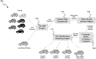
- FIG. 1 shows a schematic view of a system 100 for driver identification, in accordance with one embodiment.
- FIG. 2 shows a flowchart of a process 200 for driver identification, in accordance with one embodiment.
- FIG. 3 shows a computer system 300 in which the process 200 for driver identification can be implemented, in accordance with one embodiment.
- the various embodiments of the invention pertain to techniques for identifying a driver of a vehicle based on recorded telematics data that describes a “signature” driving style for a driver.
- Real-time data collected by sensors can be used as input to identify whether a specific driver is driving.
- some in-vehicle or mobile sensors that can be used to collect data include Global Positioning System (GPS) sensors, accelerometers, three-axis gyroscopes, etc.
- GPS Global Positioning System
- a feature matrix is then defined, which encodes driving behaviors from the recorded GPS data, using deep neural networks to identify the specific driver.
- New trip data for driver classification is continually ingested and used for clustering. This makes it possible for the neural network to automatically learn the driving signatures of different drivers without any human intervention, which generates better early results, and has a greater potential to improve with more data and sophisticated network input.
- Such business initiatives may include:
- FIG. 1 shows a schematic system 100 for driver identification, in accordance with one embodiment of the invention
- FIG. 2 shows a flowchart of a process 200 for driver identification, in accordance with one embodiment of the invention.
- the system 100 includes a trip split engine 102 , a feature map transformer 104 , a deep neural network model engine 106 , a similarity model engine 108 , and a trip classification/clustering engine 110 .
- the trip split engine 102 receives sequences of measurements, such as real-time GPS data, collected by sensors in the vehicles.
- sequences of measurements such as real-time GPS data
- GPS data is only one example, and there may be many other types of sensors that generate measurement values relating to the movement of a vehicle, such as accelerometers, gyroscopes, etc.
- the sampling rate of the sensors is sufficiently high.
- the sampling rate may be approximately 1 Hz.
- the received measurements are grouped into trip segments.
- the segmentation is done by the dividing of a trip (which could be arbitrary duration of time) into smaller normalized sub-trips with reasonable length (e.g., 120 seconds), and then each sub-trip is transformed to a corresponding feature map and for further analytics, e.g., calculating distance.
- the trip split engine 102 sends the trip segments to the feature map transformer 104 .
- the feature map transformer 104 defines instantaneous basic features from the received trip segments, such as speed (direction, norm, etc.); changes of speed direction, norm, etc.; acceleration (direction, norm, etc.); changes of acceleration direction, norm, etc.; angular speed (direction, norm, etc.), and changes of angular speed direction, norm, etc.
- the feature map transformer 104 also calculates statistical features for each basic feature within a given time frame, for example, 5 seconds, in step 206 .
- the statistical features can include, for example, mean, median, min, max, standard deviation, quantities, histograms, etc., as is familiar to those having ordinary skill in the statistics art.
- the feature map transformer 104 uses the statistical features to build a feature map in step 208 , in which one axis represents the time frame and the other axes represent the calculated statistical features and their values.
- the feature map is then transferred from the feature map transformer 104 to the deep neural network model engine 106 .
- the deep neural network model engine 106 extracts a set of driving features in step 210 , using deep Convolutional Neural Networks (CNNs) and/or Recurrent Neural Networks (RNNs), from the received feature map.
- the features are complex combinations of vehicle movements including speed, acceleration, and angular speed, etc., and statistics describing their distributions in a short time period.
- the extracted driving features are then transferred to the similarity model engine 108 .
- the similarity model engine 108 uses the outputs of the last fully connected layer in the neural network model engine as inputs and applies a distance function to determine the maximum, minimum or average distance between two trip segments as the distance of the corresponding trips.
- the goal is to calculate the similarity between trips (or trip segments) in terms of driving habits/style. Similar trips indicate that these trips are possibly driven by a same driver.
- Some examples of the distance functions that can be used to determine the maximum, minimum or average distance include Euclidean distance, Cosine distance, or Mahalanobis distance. Those with expertise in this area can apply many other types of distance functions.
- the output from the similarity model engine 108 is a set of similarity metrics.
- the similarity metrics are then transferred to the trip classification/clustering engine 110 .
- the trip classification/clustering engine 110 can operate in two different modes; a training mode and a testing mode.
- the training mode the trip classification/clustering engine 110 receives the similarity metrics from the similarity model engine 108 and uses the similarity metrics to train a classification model or clustering model, step 214 .
- Some examples of clustering models include a Support Vector Machine (SVM) model, and a K-means model. It should be realized that these are just a couple of examples of models that can be used, and many others are within the grasp of those having ordinary skill in the art.
- SVM Support Vector Machine
- the trip classification/clustering engine 110 can be used in the testing mode, as shown in step 216 .
- Computational time for the model depends on data size and algorithm complexity. The number of cases can be flexible as in real-world applications.
- classes refers to patterns with known labels (e.g., driver IDs) in supervised learning paradigms.
- clusters refers to patterns with unknown labels in unsupervised learning paradigms, where the ground truth is unknown and can only be inferred from data.
- the classifiers/clusters are output. If the data does not belong to an existing class or cluster the trip classification/clustering engine 110 switches to the training mode and further improves the classification model based on the incoming data. By continually ingesting data for new trips and drivers into the system, the classification models can be significantly improved and driver signatures can be more accurately classified.
- Context data can be calibrated to the feature maps (inputs of the neural networks) as new rows, which can be seen as adding additional features, so that the neural networks can automatically discover the correlation between contexts and other vehicle movement features during training, and thus find more useful patterns for driver identification.
- FIG. 3 shows a schematic view of a computer system in which various embodiments of the present invention can be implemented.
- the computer system 12 may include, but are not limited to, one or more processors or processing units 16 , a system memory 28 , and a bus 18 that couples various system components including system memory 28 to processor 16 .
- Bus 18 represents one or more of any of several types of bus structures, including a memory bus or memory controller, a peripheral bus, an accelerated graphics port, and a processor or local bus using any of a variety of bus architectures.
- bus architectures include Industry Standard Architecture (ISA) bus, Micro Channel Architecture (MCA) bus, Enhanced ISA (EISA) bus, Video Electronics Standards Association (VESA) local bus, and Peripheral Component Interconnect (PCI) bus.
- Computer system 12 typically includes a variety of computer system readable media. Such media may be any available media that is accessible by computer system 12 , and it includes both volatile and non-volatile media, removable and non-removable media.
- System memory 28 can include computer system readable media in the form of volatile memory, such as random access memory (RAM) 30 and/or cache memory 32 .
- Computer system 12 may further include other removable/non-removable, volatile/non-volatile computer system storage media.
- storage system 34 can be provided for reading from and writing to a non-removable, non-volatile magnetic media (not shown and typically called a “hard drive”).
- a magnetic disk drive for reading from and writing to a removable, non-volatile magnetic disk (e.g., a “floppy disk”).
- an optical disk drive for reading from or writing to a removable, non-volatile optical disk such as a CD-ROM, DVD-ROM or other optical media can be provided.
- memory 28 may include at least one program product having a set (e.g., at least one) of program modules that are configured to carry out the functions of embodiments of the invention.
- Program/utility 40 having a set (at least one) of program modules 42 , may be stored in memory 28 by way of example, and not limitation, as well as an operating system, one or more application programs, other program modules, and program data. Each of the operating system, one or more application programs, other program modules, and program data or some combination thereof, may include an implementation of a networking environment.
- Program modules 42 generally carry out the functions and/or methodologies of embodiments of the invention as described herein.
- Computer system 12 may also communicate with one or more external devices 14 such as a keyboard, a pointing device, a display 24 , etc.; one or more devices that enable a user to interact with computer system 12 ; and/or any devices (e.g., network card, modem, etc.) that enable computer system/server 12 to communicate with one or more other computing devices. Such communication can occur via Input/Output (I/O) interfaces 22 . Still yet, computer system 12 can communicate with one or more networks such as a local area network (LAN), a general wide area network (WAN), and/or a public network (e.g., the Internet) via network adapter 20 . As depicted, network adapter 20 communicates with the other components of computer system 12 via bus 18 . It should be understood that although not shown, other hardware and/or software components could be used in conjunction with computer system 12 . Examples, include, but are not limited to: microcode, device drivers, and redundant processing units.
- the present invention may be a system, a method, and/or a computer program product at any possible technical detail level of integration
- the computer program product may include a computer readable storage medium (or media) having computer readable program instructions thereon for causing a processor to carry out aspects of the present invention
- the computer readable storage medium can be a tangible device that can retain and store instructions for use by an instruction execution device.
- the computer readable storage medium may be, for example, but is not limited to, an electronic storage device, a magnetic storage device, an optical storage device, an electromagnetic storage device, a semiconductor storage device, or any suitable combination of the foregoing.
- a non-exhaustive list of more specific examples of the computer readable storage medium includes the following: a portable computer diskette, a hard disk, a random access memory (RAM), a read-only memory (ROM), an erasable programmable read-only memory (EPROM or Flash memory), a static random access memory (SRAM), a portable compact disc read-only memory (CD-ROM), a digital versatile disk (DVD), a memory stick, a floppy disk, a mechanically encoded device such as punch-cards or raised structures in a groove having instructions recorded thereon, and any suitable combination of the foregoing.
- RAM random access memory
- ROM read-only memory
- EPROM or Flash memory erasable programmable read-only memory
- SRAM static random access memory
- CD-ROM compact disc read-only memory
- DVD digital versatile disk
- memory stick a floppy disk
- a mechanically encoded device such as punch-cards or raised structures in a groove having instructions recorded thereon
- a computer readable storage medium is not to be construed as being transitory signals per se, such as radio waves or other freely propagating electromagnetic waves, electromagnetic waves propagating through a waveguide or other transmission media (e.g., light pulses passing through a fiber-optic cable), or electrical signals transmitted through a wire.
- Computer readable program instructions described herein can be downloaded to respective computing/processing devices from a computer readable storage medium or to an external computer or external storage device via a network, for example, the Internet, a local area network, a wide area network and/or a wireless network.
- the network may comprise copper transmission cables, optical transmission fibers, wireless transmission, routers, firewalls, switches, gateway computers and/or edge servers.
- a network adapter card or network interface in each computing/processing device receives computer readable program instructions from the network and forwards the computer readable program instructions for storage in a computer readable storage medium within the respective computing/processing device.
- Computer readable program instructions for carrying out operations of the present invention may be assembler instructions, instruction-set-architecture (ISA) instructions, machine instructions, machine dependent instructions, microcode, firmware instructions, state-setting data, configuration data for integrated circuitry, or either source code or object code written in any combination of one or more programming languages, including an object oriented programming language such as Smalltalk, C++, or the like, and procedural programming languages, such as the “C” programming language or similar programming languages.
- the computer readable program instructions may execute entirely on the user's computer, partly on the user's computer, as a stand-alone software package, partly on the user's computer and partly on a remote computer or entirely on the remote computer or server.
- the remote computer may be connected to the user's computer through any type of network, including a local area network (LAN) or a wide area network (WAN), or the connection may be made to an external computer (for example, through the Internet using an Internet Service Provider).
- electronic circuitry including, for example, programmable logic circuitry, field-programmable gate arrays (FPGA), or programmable logic arrays (PLA) may execute the computer readable program instructions by utilizing state information of the computer readable program instructions to personalize the electronic circuitry, in order to perform aspects of the present invention.
- These computer readable program instructions may be provided to a processor of a general purpose computer, special purpose computer, or other programmable data processing apparatus to produce a machine, such that the instructions, which execute via the processor of the computer or other programmable data processing apparatus, create means for implementing the functions/acts specified in the flowchart and/or block diagram block or blocks.
- These computer readable program instructions may also be stored in a computer readable storage medium that can direct a computer, a programmable data processing apparatus, and/or other devices to function in a particular manner, such that the computer readable storage medium having instructions stored therein comprises an article of manufacture including instructions which implement aspects of the function/act specified in the flowchart and/or block diagram block or blocks.
- the computer readable program instructions may also be loaded onto a computer, other programmable data processing apparatus, or other device to cause a series of operational steps to be performed on the computer, other programmable apparatus or other device to produce a computer implemented process, such that the instructions which execute on the computer, other programmable apparatus, or other device implement the functions/acts specified in the flowchart and/or block diagram block or blocks.
- each block in the flowchart or block diagrams may represent a module, segment, or portion of instructions, which comprises one or more executable instructions for implementing the specified logical function(s).
- the functions noted in the blocks may occur out of the order noted in the Figures.
- two blocks shown in succession may, in fact, be executed substantially concurrently, or the blocks may sometimes be executed in the reverse order, depending upon the functionality involved.
Landscapes
- Engineering & Computer Science (AREA)
- Physics & Mathematics (AREA)
- Theoretical Computer Science (AREA)
- Mathematical Physics (AREA)
- Biomedical Technology (AREA)
- General Engineering & Computer Science (AREA)
- Biophysics (AREA)
- Computational Linguistics (AREA)
- Data Mining & Analysis (AREA)
- Evolutionary Computation (AREA)
- General Health & Medical Sciences (AREA)
- Molecular Biology (AREA)
- Computing Systems (AREA)
- Artificial Intelligence (AREA)
- General Physics & Mathematics (AREA)
- Life Sciences & Earth Sciences (AREA)
- Software Systems (AREA)
- Health & Medical Sciences (AREA)
- Automation & Control Theory (AREA)
- Transportation (AREA)
- Mechanical Engineering (AREA)
- Traffic Control Systems (AREA)
Abstract
Description
-
- Improved risk profiling
- Improved understanding of driver habits—Does the driver speed? Does he break suddenly? Is he unable to drive straight? Is he unable to properly control a car in the snow? etc. This has the potential to drive more accurate pricing for current insurance cycles, renewals and future car policies, which currently do not rely on how safe a driver actually is, but just on general facts such as car type, car age, driver age, driver sex, driver accident record, driver ticket record, car parking profile, car use profile, driver state/county of residence, etc.
- It will give insurance underwriters much more insight into the real risk profiles for drivers.
- New levels of understanding the impact of environmental conditions on driving (e.g., bad weather, smog, sun glare, traffic flow, etc.)
- Tired or fatigued warnings/evaluations.
- Productivity/shift management extensions.
- Driver performance evaluations.
- Route optimization insights.
Claims (17)
Priority Applications (1)
| Application Number | Priority Date | Filing Date | Title |
|---|---|---|---|
| US15/409,817 US11106969B2 (en) | 2017-01-19 | 2017-01-19 | Method and apparatus for driver identification leveraging telematics data |
Applications Claiming Priority (1)
| Application Number | Priority Date | Filing Date | Title |
|---|---|---|---|
| US15/409,817 US11106969B2 (en) | 2017-01-19 | 2017-01-19 | Method and apparatus for driver identification leveraging telematics data |
Publications (2)
| Publication Number | Publication Date |
|---|---|
| US20180204119A1 US20180204119A1 (en) | 2018-07-19 |
| US11106969B2 true US11106969B2 (en) | 2021-08-31 |
Family
ID=62840955
Family Applications (1)
| Application Number | Title | Priority Date | Filing Date |
|---|---|---|---|
| US15/409,817 Expired - Fee Related US11106969B2 (en) | 2017-01-19 | 2017-01-19 | Method and apparatus for driver identification leveraging telematics data |
Country Status (1)
| Country | Link |
|---|---|
| US (1) | US11106969B2 (en) |
Families Citing this family (14)
| Publication number | Priority date | Publication date | Assignee | Title |
|---|---|---|---|---|
| US11106969B2 (en) * | 2017-01-19 | 2021-08-31 | International Business Machines Corporation | Method and apparatus for driver identification leveraging telematics data |
| CN111309486B (en) * | 2018-08-10 | 2024-01-12 | 中科寒武纪科技股份有限公司 | Conversion method, conversion device, computer equipment and storage medium |
| US11685386B2 (en) * | 2018-12-03 | 2023-06-27 | Honda Motor Co., Ltd. | System and method for determining a change of a customary vehicle driver |
| US11162802B2 (en) | 2019-10-28 | 2021-11-02 | Allstate Insurance Company | Systems and methods for classifying vehicle trips |
| CN113157817B (en) * | 2021-03-15 | 2024-05-10 | 平安科技(深圳)有限公司 | Method, device and computer equipment for distinguishing drivers |
| CN113705802B (en) * | 2021-07-26 | 2023-09-08 | 深圳市易成自动驾驶技术有限公司 | Synchronous calculation method, device, system, program product and medium for automatic driving |
| CN113460059B (en) * | 2021-08-16 | 2022-08-26 | 吉林大学 | Device and method for identifying driving enthusiasm of driver based on intelligent steering wheel |
| CN113705446B (en) * | 2021-08-27 | 2023-04-07 | 电子科技大学 | Open set identification method for individual radiation source |
| CN113742726B (en) * | 2021-08-27 | 2024-10-15 | 恒安嘉新(北京)科技股份公司 | Program identification model training and program identification method, device, equipment and medium |
| CN116258919A (en) * | 2021-12-09 | 2023-06-13 | 逸驾智能科技有限公司 | Methods, devices, media and program products for acquiring data |
| CN115438711B (en) * | 2022-07-26 | 2025-12-05 | 中智行(苏州)科技有限公司 | A distributed multi-level perception fusion method, device, equipment, and storage medium based on vehicle-road cooperation |
| US12489672B2 (en) * | 2022-08-28 | 2025-12-02 | VMware LLC | Dynamic use of multiple wireless network links to connect a vehicle to an SD-WAN |
| CN116403017A (en) * | 2023-04-28 | 2023-07-07 | 东风商用车有限公司 | A method and device for classifying driving characteristics based on mean value clustering algorithm |
| CN119249159B (en) * | 2024-12-06 | 2025-09-12 | 杭州瑞欧科技有限公司 | A pesticide data compensation fee identification method, system, device and medium |
Citations (11)
| Publication number | Priority date | Publication date | Assignee | Title |
|---|---|---|---|---|
| US7983835B2 (en) * | 2004-11-03 | 2011-07-19 | Lagassey Paul J | Modular intelligent transportation system |
| US20110313988A1 (en) * | 2009-12-01 | 2011-12-22 | Rishab Aiyer Ghosh | System and method for search of sources and targets based on relative topicality specialization of the targets |
| US8260515B2 (en) | 2008-07-24 | 2012-09-04 | GM Global Technology Operations LLC | Adaptive vehicle control system with driving style recognition |
| US20130018968A1 (en) * | 2011-07-14 | 2013-01-17 | Yahoo! Inc. | Automatic profiling of social media users |
| US8634980B1 (en) | 2010-10-05 | 2014-01-21 | Google Inc. | Driving pattern recognition and safety control |
| US9158962B1 (en) * | 2014-05-07 | 2015-10-13 | Lytx, Inc. | Passive driver identification |
| US20150307106A1 (en) * | 2014-04-28 | 2015-10-29 | Ford Global Technologies, Llc | Driver behavior based vehicle application recommendation |
| US20160221592A1 (en) * | 2013-11-27 | 2016-08-04 | Solfice Research, Inc. | Real Time Machine Vision and Point-Cloud Analysis For Remote Sensing and Vehicle Control |
| US20170032281A1 (en) * | 2015-07-29 | 2017-02-02 | Illinois Tool Works Inc. | System and Method to Facilitate Welding Software as a Service |
| US20180025249A1 (en) * | 2016-07-25 | 2018-01-25 | Mitsubishi Electric Research Laboratories, Inc. | Object Detection System and Object Detection Method |
| US20180204119A1 (en) * | 2017-01-19 | 2018-07-19 | International Business Machines Corporation | Method and Apparatus for Driver Identification Leveraging Telematics Data |
-
2017
- 2017-01-19 US US15/409,817 patent/US11106969B2/en not_active Expired - Fee Related
Patent Citations (13)
| Publication number | Priority date | Publication date | Assignee | Title |
|---|---|---|---|---|
| US7983835B2 (en) * | 2004-11-03 | 2011-07-19 | Lagassey Paul J | Modular intelligent transportation system |
| US8260515B2 (en) | 2008-07-24 | 2012-09-04 | GM Global Technology Operations LLC | Adaptive vehicle control system with driving style recognition |
| US20110313988A1 (en) * | 2009-12-01 | 2011-12-22 | Rishab Aiyer Ghosh | System and method for search of sources and targets based on relative topicality specialization of the targets |
| US8634980B1 (en) | 2010-10-05 | 2014-01-21 | Google Inc. | Driving pattern recognition and safety control |
| US20130018968A1 (en) * | 2011-07-14 | 2013-01-17 | Yahoo! Inc. | Automatic profiling of social media users |
| US20160221592A1 (en) * | 2013-11-27 | 2016-08-04 | Solfice Research, Inc. | Real Time Machine Vision and Point-Cloud Analysis For Remote Sensing and Vehicle Control |
| US20150307106A1 (en) * | 2014-04-28 | 2015-10-29 | Ford Global Technologies, Llc | Driver behavior based vehicle application recommendation |
| US20150379331A1 (en) * | 2014-05-07 | 2015-12-31 | Lytx, Inc. | Passive driver identification |
| US9158962B1 (en) * | 2014-05-07 | 2015-10-13 | Lytx, Inc. | Passive driver identification |
| US9501690B2 (en) * | 2014-05-07 | 2016-11-22 | Lytx, Inc. | Passive driver identification |
| US20170032281A1 (en) * | 2015-07-29 | 2017-02-02 | Illinois Tool Works Inc. | System and Method to Facilitate Welding Software as a Service |
| US20180025249A1 (en) * | 2016-07-25 | 2018-01-25 | Mitsubishi Electric Research Laboratories, Inc. | Object Detection System and Object Detection Method |
| US20180204119A1 (en) * | 2017-01-19 | 2018-07-19 | International Business Machines Corporation | Method and Apparatus for Driver Identification Leveraging Telematics Data |
Non-Patent Citations (4)
| Title |
|---|
| Choi et al; "Analysis and Classification of Driver Behavior using In-Vehicle CAN-Bus Information"; Erik Jonsson School of Engineering and Computer Science, University of Texas at Dallas; 2007; 6 pp. |
| Liu et al; "Learning Drivers' Behaviour with Deep Neural Networks"; Carnegie Mellon University Silicon Valley; Project Sponsor: TOYOTA InfoTechnology Center; 1 page. |
| Quintero et al; "Driver Behavior Classification Model based on an Intelligent Driving Diagnosis System"; 2012 15th International IEEE Conference on Intelligent Transportation Systems Anchorage, Alaska, USA, Sep. 16-19, 2012. 6 pp. |
| Wakita et al; "Driver Identification Using Driving Behavior Signals"; IEICE Trans. Inf. & Syst., vol. E89-D, No. 3; Oxford University Press Oxford, UK; Mar. 2006. 8 pp. |
Also Published As
| Publication number | Publication date |
|---|---|
| US20180204119A1 (en) | 2018-07-19 |
Similar Documents
| Publication | Publication Date | Title |
|---|---|---|
| US11106969B2 (en) | Method and apparatus for driver identification leveraging telematics data | |
| US12044539B2 (en) | Data processing system communicating with a map data processing system to determine or alter a navigation path based on one or more road segments | |
| US11735037B2 (en) | Method and system for determining traffic-related characteristics | |
| US12118470B2 (en) | System for predicting aggressive driving | |
| US10814815B1 (en) | System for determining occurrence of an automobile accident and characterizing the accident | |
| Shirazi et al. | Looking at intersections: a survey of intersection monitoring, behavior and safety analysis of recent studies | |
| US10885590B2 (en) | Granting access to a blockchain ledger | |
| US20180322230A1 (en) | Driverless vehicle simulation test method and apparatus, device and readable medium | |
| CN110443185B (en) | Driver identification method, driver identification device, electronic device, and storage medium | |
| Sun et al. | Combining machine learning and dynamic time wrapping for vehicle driving event detection using smartphones | |
| CN114970705B (en) | Running state analysis method, device, equipment and medium based on multi-sensing data | |
| US12306010B1 (en) | Resolving inconsistencies in vehicle guidance maps | |
| EP3382570A1 (en) | Method for characterizing driving events of a vehicle based on an accelerometer sensor | |
| Woo et al. | Manoeuvre segmentation using smartphone sensors | |
| WO2022025244A1 (en) | Vehicle accident prediction system, vehicle accident prediction method, vehicle accident prediction program, and trained model generation system | |
| US12154346B2 (en) | Estimating object uncertainty using a pre-non-maximum suppression ensemble | |
| US11644331B2 (en) | Probe data generating system for simulator | |
| Zeng et al. | On the importance of contextual information for building reliable automated driver identification systems | |
| Ali et al. | Real-time snowy weather detection based on machine vision and vehicle kinematics: A non-parametric data fusion analysis protocol | |
| Das et al. | Why slammed the brakes on? auto-annotating driving behaviors from adaptive causal modeling | |
| Ali et al. | Employment of instrumented vehicles to identify real-time snowy weather conditions on freeways using supervised machine learning techniques–A naturalistic driving study | |
| CN118225122A (en) | Intelligent lane recommendation navigation method and system | |
| US20250087033A1 (en) | Systems and methods for predicting driving behaviors of users by generating synthetic trips | |
| US20230214694A1 (en) | Data processing method and electronic device | |
| CN120766513A (en) | Automatic driving condition permission decision method, device and terminal equipment |
Legal Events
| Date | Code | Title | Description |
|---|---|---|---|
| AS | Assignment |
Owner name: INTERNATIONAL BUSINESS MACHINES CORPORATION, NEW YORK Free format text: ASSIGNMENT OF ASSIGNORS INTEREST;ASSIGNORS:ANDERSON, JOHN C.;DONG, WEI S.;LI, CHANG S.;AND OTHERS;SIGNING DATES FROM 20170106 TO 20170119;REEL/FRAME:041015/0346 Owner name: INTERNATIONAL BUSINESS MACHINES CORPORATION, NEW Y Free format text: ASSIGNMENT OF ASSIGNORS INTEREST;ASSIGNORS:ANDERSON, JOHN C.;DONG, WEI S.;LI, CHANG S.;AND OTHERS;SIGNING DATES FROM 20170106 TO 20170119;REEL/FRAME:041015/0346 |
|
| STPP | Information on status: patent application and granting procedure in general |
Free format text: DOCKETED NEW CASE - READY FOR EXAMINATION |
|
| STPP | Information on status: patent application and granting procedure in general |
Free format text: NON FINAL ACTION MAILED |
|
| STPP | Information on status: patent application and granting procedure in general |
Free format text: RESPONSE TO NON-FINAL OFFICE ACTION ENTERED AND FORWARDED TO EXAMINER |
|
| STPP | Information on status: patent application and granting procedure in general |
Free format text: DOCKETED NEW CASE - READY FOR EXAMINATION |
|
| STPP | Information on status: patent application and granting procedure in general |
Free format text: RESPONSE TO NON-FINAL OFFICE ACTION ENTERED AND FORWARDED TO EXAMINER |
|
| STPP | Information on status: patent application and granting procedure in general |
Free format text: NOTICE OF ALLOWANCE MAILED -- APPLICATION RECEIVED IN OFFICE OF PUBLICATIONS |
|
| STPP | Information on status: patent application and granting procedure in general |
Free format text: AWAITING TC RESP., ISSUE FEE NOT PAID |
|
| STPP | Information on status: patent application and granting procedure in general |
Free format text: NOTICE OF ALLOWANCE MAILED -- APPLICATION RECEIVED IN OFFICE OF PUBLICATIONS |
|
| STCF | Information on status: patent grant |
Free format text: PATENTED CASE |
|
| FEPP | Fee payment procedure |
Free format text: MAINTENANCE FEE REMINDER MAILED (ORIGINAL EVENT CODE: REM.); ENTITY STATUS OF PATENT OWNER: LARGE ENTITY |
|
| LAPS | Lapse for failure to pay maintenance fees |
Free format text: PATENT EXPIRED FOR FAILURE TO PAY MAINTENANCE FEES (ORIGINAL EVENT CODE: EXP.); ENTITY STATUS OF PATENT OWNER: LARGE ENTITY |
|
| STCH | Information on status: patent discontinuation |
Free format text: PATENT EXPIRED DUE TO NONPAYMENT OF MAINTENANCE FEES UNDER 37 CFR 1.362 |
|
| FP | Lapsed due to failure to pay maintenance fee |
Effective date: 20250831 |