US11096719B2 - Optical bladeless obturator - Google Patents
Optical bladeless obturator Download PDFInfo
- Publication number
- US11096719B2 US11096719B2 US16/435,343 US201916435343A US11096719B2 US 11096719 B2 US11096719 B2 US 11096719B2 US 201916435343 A US201916435343 A US 201916435343A US 11096719 B2 US11096719 B2 US 11096719B2
- Authority
- US
- United States
- Prior art keywords
- obturator
- transverse
- wall
- transparent
- spear
- Prior art date
- Legal status (The legal status is an assumption and is not a legal conclusion. Google has not performed a legal analysis and makes no representation as to the accuracy of the status listed.)
- Active, expires
Links
Images


Classifications
-
- A—HUMAN NECESSITIES
- A61—MEDICAL OR VETERINARY SCIENCE; HYGIENE
- A61B—DIAGNOSIS; SURGERY; IDENTIFICATION
- A61B17/00—Surgical instruments, devices or methods, e.g. tourniquets
- A61B17/34—Trocars; Puncturing needles
- A61B17/3417—Details of tips or shafts, e.g. grooves, expandable, bendable; Multiple coaxial sliding cannulas, e.g. for dilating
- A61B17/3421—Cannulas
-
- A—HUMAN NECESSITIES
- A61—MEDICAL OR VETERINARY SCIENCE; HYGIENE
- A61B—DIAGNOSIS; SURGERY; IDENTIFICATION
- A61B17/00—Surgical instruments, devices or methods, e.g. tourniquets
- A61B17/34—Trocars; Puncturing needles
- A61B17/3478—Endoscopic needles, e.g. for infusion
-
- A—HUMAN NECESSITIES
- A61—MEDICAL OR VETERINARY SCIENCE; HYGIENE
- A61B—DIAGNOSIS; SURGERY; IDENTIFICATION
- A61B17/00—Surgical instruments, devices or methods, e.g. tourniquets
- A61B17/34—Trocars; Puncturing needles
- A61B17/3494—Trocars; Puncturing needles with safety means for protection against accidental cutting or pricking, e.g. limiting insertion depth, pressure sensors
-
- A—HUMAN NECESSITIES
- A61—MEDICAL OR VETERINARY SCIENCE; HYGIENE
- A61B—DIAGNOSIS; SURGERY; IDENTIFICATION
- A61B1/00—Instruments for performing medical examinations of the interior of cavities or tubes of the body by visual or photographical inspection, e.g. endoscopes; Illuminating arrangements therefor
- A61B1/00147—Holding or positioning arrangements
-
- A—HUMAN NECESSITIES
- A61—MEDICAL OR VETERINARY SCIENCE; HYGIENE
- A61B—DIAGNOSIS; SURGERY; IDENTIFICATION
- A61B17/00—Surgical instruments, devices or methods, e.g. tourniquets
- A61B2017/00831—Material properties
- A61B2017/00902—Material properties transparent or translucent
-
- A—HUMAN NECESSITIES
- A61—MEDICAL OR VETERINARY SCIENCE; HYGIENE
- A61B—DIAGNOSIS; SURGERY; IDENTIFICATION
- A61B17/00—Surgical instruments, devices or methods, e.g. tourniquets
- A61B2017/00831—Material properties
- A61B2017/00902—Material properties transparent or translucent
- A61B2017/00907—Material properties transparent or translucent for light
-
- A—HUMAN NECESSITIES
- A61—MEDICAL OR VETERINARY SCIENCE; HYGIENE
- A61B—DIAGNOSIS; SURGERY; IDENTIFICATION
- A61B17/00—Surgical instruments, devices or methods, e.g. tourniquets
- A61B17/32—Surgical cutting instruments
- A61B2017/320044—Blunt dissectors
-
- A—HUMAN NECESSITIES
- A61—MEDICAL OR VETERINARY SCIENCE; HYGIENE
- A61B—DIAGNOSIS; SURGERY; IDENTIFICATION
- A61B17/00—Surgical instruments, devices or methods, e.g. tourniquets
- A61B17/34—Trocars; Puncturing needles
- A61B17/3417—Details of tips or shafts, e.g. grooves, expandable, bendable; Multiple coaxial sliding cannulas, e.g. for dilating
- A61B2017/3419—Sealing means between cannula and body
-
- A—HUMAN NECESSITIES
- A61—MEDICAL OR VETERINARY SCIENCE; HYGIENE
- A61B—DIAGNOSIS; SURGERY; IDENTIFICATION
- A61B17/00—Surgical instruments, devices or methods, e.g. tourniquets
- A61B17/34—Trocars; Puncturing needles
- A61B17/3417—Details of tips or shafts, e.g. grooves, expandable, bendable; Multiple coaxial sliding cannulas, e.g. for dilating
- A61B2017/3454—Details of tips
- A61B2017/3456—Details of tips blunt
-
- A—HUMAN NECESSITIES
- A61—MEDICAL OR VETERINARY SCIENCE; HYGIENE
- A61B—DIAGNOSIS; SURGERY; IDENTIFICATION
- A61B17/00—Surgical instruments, devices or methods, e.g. tourniquets
- A61B17/34—Trocars; Puncturing needles
- A61B17/3417—Details of tips or shafts, e.g. grooves, expandable, bendable; Multiple coaxial sliding cannulas, e.g. for dilating
- A61B2017/3454—Details of tips
- A61B2017/346—Details of tips with wings
-
- A—HUMAN NECESSITIES
- A61—MEDICAL OR VETERINARY SCIENCE; HYGIENE
- A61B—DIAGNOSIS; SURGERY; IDENTIFICATION
- A61B90/00—Instruments, implements or accessories specially adapted for surgery or diagnosis and not covered by any of the groups A61B1/00 - A61B50/00, e.g. for luxation treatment or for protecting wound edges
- A61B90/08—Accessories or related features not otherwise provided for
- A61B2090/0801—Prevention of accidental cutting or pricking
Definitions
- the present application relates to a minimally invasive surgical instrument, and in particular, to a trocar obturator.
- a trocar is a surgical instrument that is used to establish an artificial access in minimally invasive surgery (especially in rigid endoscopy).
- a trocar assembly generally comprise in general a cannula and an obturator.
- a trocar assembly usually, limiting the side that is the obturator and the cannula close to the handle of the surgeon is proximal end, the side that is away from the hand and preferentially penetrates the body cavity is the distal end.
- the general clinical use is as follows: firstly cut a small incision on the patient's skin, and then pass the obturator through the cannula, the distal end of the obturator exceeds the distal end of the cannula, and then through the skin opening penetrating the body wall into the body cavity.
- the obturator usually includes a selective-axial-moved protective shield and an automatic lock device, which is called an automatic protective obturator with blade (hereinafter referred to as a protective obturator).
- an automatic protective obturator with blade hereinafter referred to as a protective obturator.
- the protective shield contacts the patient's interior organs or tissues in an impact manner, which may still cause varying degrees of unpredictable damage.
- the manner of penetrating into the body is rotating back and forth in a small range instead of a simple linear motion.
- the round-trip rotary manner is beneficial for tearing and swelling muscle tissue, and for controlling the penetration speed and reducing the aforementioned inertia effect.
- the blade of the protective obturator rotates back and forth and cuts muscle tissue, resulting in irregular wounds, thereby additionally increasing the damage to the patient, and increasing the occurrence probability of incision hernia complication.
- the obturator without blade (hereinafter referred to as the bladeless obturator) is beneficial for reducing damage to the patient.
- the distal end of the bladeless obturator penetrates the muscle and tissue due to the absence of a sharp blade, separates the muscle fiber and swells the wound until the obturator and the cannula assembly passing through the body wall.
- the bladeless obturator reduces the cutting damage to the muscle tissue, helps the postoperative recovery, and helps reducing the probability of incision hernia complication.
- the penetration force is generally larger than which of protective obturator, so it is more difficult to control, and the risk of damage to organs and tissues for the patient is increased.
- U.S. Pat. No. 5,569,292 discloses a transparent bladeless obturator comprising an elongate shaft and a transparent conical penetrating tip.
- the endoscope When using the transparent bladeless obturator, the endoscope is inserted into the hollow shaft.
- the endoscope is connected to a light source to provide illumination through the transparent penetrating tip and tissue wrapped in the outer surface of the transparent tip. It is also connected to a video monitor to display the illuminated images transmitted from the surgical site. In this way, the user can readily monitor the advance of trocar through bodily tissue from video.
- the present invention proposes an improved transparent bladeless obturator.
- one object of the invention is to provide an improved optical bladeless obturator.
- an optical bladeless obturator comprises a proximal handle and a distal-end portion and a shaft there between, said handle and said shaft including a generally-aligned axis aperture, said distal-end portion including a transparent tip.
- Said transparent tip comprising a top-portion, a spear-portion, a transition-portion and a base-portion.
- the top-portion includes an apex and a rotary-wall extending axially from the apex to the proximal end and gradually increasing in a transverse direction, the rotary-wall shaping a hollow cone; the spear-portion including a sweeping-wall, the rotary-wall and the sweeping-wall extend to be intersected and form a circular field of vision.
- the circular field of vision facilitates clearer imaging and less distortion of the apex and its adjacent region.
- the sweeping-wall extends axially from the distal end to the proximal end and gradually increases in a transverse direction.
- the spear-portion includes the first transverse-portion and the second transverse-portion that are substantially perpendicular to each other, and the dimension of the first transverse-portion is greater than the dimension of the second transverse-portion.
- the transverse dimension ratio of the first transverse-portion and the second transverse-portion is gradually reduce from the distal end to the proximal end.
- the cross section of the spear-portion is an elliptical-shape.
- the cross section of the spear-portion is approximately an elliptical polygon.
- the size of the circular field of vision conforms to the following equation: 2 mm ⁇ D ⁇ 0.5 D 0, wherein:
- D0 the maximum outer diameter of the distal-end portion of the obturator.
- an obturator comprises a proximal handle and a distal-end portion and a shaft there between, said handle and said shaft including a generally-aligned axis aperture, said distal-end portion including a transparent tip. From the distal end to the proximal end, said transparent tip is divided into a top-portion, a spear-portion, a main-portion and a base-portion.
- the top-portion includes an apex and a rotary-wall extending axially from the apex to the proximal end and gradually increasing in a transverse direction, the rotary-wall shaping a hollow cone; the main-portion including a main-body wall, the rotary-wall and the main-body extend to be intersected and form a circular field of vision.
- the main-body wall extends axially from the distal end toward the proximal end and gradually increases in a transverse direction, and the thickness of the rotary-wall is smaller than the wall thickness of the main-body wall. The thinner the thickness of the top-portion, the more advantageous it is to reduce light loss and obtain a clearer image.
- an obturator comprises a proximal handle and a distal-end portion and a shaft there between, said handle and said shaft including a generally-aligned axis aperture, said distal-end portion including a transparent tip. From the distal end to the proximal end, said transparent tip is divided into a top-portion, a spear-portion, a transition-portion and a base-portion.
- the top-portion includes an apex and a rotary-wall extending axially from the apex to the proximal end and gradually increasing in a transverse direction, the rotary-wall limiting a hollow cone.
- the spear-portion includes a sweeping-wall, which extends axially from the distal end to the proximal end and gradually increases in a transverse direction.
- the spear-portion includes the first transverse-portion and the second transverse-portion that are substantially perpendicular to each other, and the dimension of the first transverse-portion is larger than the dimension of the second transverse-portion.
- the first transverse-portion extends transversely to form a blunt-separating portion.
- the transparent tip includes at least one thin working-edge, the working-edge extends transversely outward from the second transverse-portion, the working-edge substantially perpendicular to the first transverse-portion.
- the rotary-wall and the sweeping-wall extend to be intersected and form a circular field of vision.
- the cross section of the spear-portion is an oval-shape or approximately an oval-polygon.
- the transition-portion includes the first transverse-portion and the second transverse-portion that are substantially perpendicular to each other, and a transverse dimension of the first transverse-portion is greater than the dimension of the second transverse-portion, which is asymmetrical, that is, the half of the second transverse-portion has a larger dimension than the other half of it.
- the transparent tip includes two working-blades.
- Another object of the invention is to provide a trocar, which comprises a cannula and a optical obturator.
- FIG. 1 is a 3D perspective view of trocar assembly
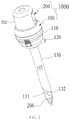
- FIG. 2 is a 3D perspective view of the obturator in the first embodiment of the invention
- FIG. 3 is a 3D perspective view of the obturator in FIG. 2 ;
- FIG. 4 is a 3D perspective view of the cam lock in FIG. 3 ;
- FIG. 5 shows a partial-section view of the obturator of the handle-portion in FIG. 2 ;
- FIG. 6 is a front projection view of the obturator in FIG. 2 ;
- FIG. 7 is a cross-section view taken along line 7 - 7 of FIG. 6 ;
- FIG. 8 is a simulated view of trocar in FIG. 1 in the clinical application
- FIG. 9 is a simulated view of distal-end portion in FIG. 1 in the clinical application.
- FIG. 10 is a side projection view of the transparent tip 650 in the prior art.
- FIG. 11 is a projection view of the transparent tip from the proximal end to the distal end in FIG. 10 ;
- FIG. 12 is a side projection view of the transparent tip 750 in the prior art
- FIG. 13 is a projection view of the transparent tip from the proximal end to the distal end in FIG. 12 ;
- FIG. 14 is a 3D perspective view of the transparent tip 850 in the prior art.
- FIG. 15 is a side projection view of the transparent tip 950 in the prior art
- FIG. 16 shows a longitudinal-section view of the transparent tip in FIG. 14 ;
- FIG. 17 is a projection view of the transparent tip from the proximal end to the distal end in FIG. 14 ;
- FIG. 18 shows a longitudinal-section view of the transparent tip in FIG. 15 ;
- FIG. 19 is a projection view of the transparent tip from the proximal end to the distal end in FIG. 15 ;
- FIG. 20 is a 3D perspective view of the transparent tip in FIG. 3 ;
- FIG. 21 is a projection view of the transparent tip from the proximal end to the distal end in FIG. 20 ;
- FIG. 22 is a partial-enlarged-simulated view of the transparent tip of FIG. 20 in the clinical application.
- FIG. 23 is a side projection view of the transparent tip in FIG. 20 ;
- FIG. 23A is a cross-section view taken along line 23 A- 23 A of FIG. 23 ;
- FIG. 23B is a cross-section view taken along line 23 B- 23 B of FIG. 23 ;
- FIG. 23C is a cross-section view taken along line 23 C- 23 C of FIG. 23 ;
- FIG. 23D is a cross-section view taken along line 23 D- 23 D of FIG. 23 ;
- FIG. 23E is a cross-section view taken along line 23 E- 23 E of FIG. 23 ;
- FIG. 24 is a 3D perspective view of the distal-end portion in the second embodiment of the invention.
- FIG. 25 shows a longitudinal-section view of the distal-end portion in FIG. 24 ;
- FIG. 26 is a projection view of the distal-end portion from the proximal end to the distal end in FIG. 24 ;
- FIG. 27 is a 3D perspective view of the distal-end portion in the third embodiment of the invention.
- FIG. 28 is a projection view of the distal-end portion from the proximal end to the distal end in FIG. 27 ;
- FIG. 29 is a projection view of the distal-end portion from the proximal end to the distal end in FIG. 27 ;
- FIG. 30 is a side projection view of the distal-end portion in FIG. 27 ;
- FIG. 30A is a cross-section view taken along line 30 A- 30 A of FIG. 30 ;
- FIG. 30B is a cross-section view taken along line 30 B- 30 B of FIG. 30 ;
- FIG. 30C is a cross-section view taken along line 30 C- 30 C of FIG. 30 ;
- FIG. 30D is a cross-section view taken along line 30 D- 30 D of FIG. 30 ;
- FIG. 30E is a cross-section view taken along line 30 E- 30 E of FIG. 30 ;
- FIG. 31-33 is a simulated view of the distal-end portion of FIG. 27 in the clinical application.
- FIG. 34 is a side projection view of the distal-end portion in the fourth embodiment of the invention.
- FIG. 35 is a side projection view of the distal-end portion in FIG. 34 ;
- FIG. 36 is a cross-section view taken along line 36 - 36 of FIG. 34 ;
- FIG. 37 is a cross-section view taken along line 37 - 37 of FIG. 34 ;
- FIG. 38 is a 3D perspective view of the distal-end portion in the fifth embodiment of the invention.
- FIG. 39 is a side projection view of the distal-end portion in FIG. 38 ;
- FIG. 40 is a cross-section view taken along line 40 - 40 of FIG. 38 ;
- FIG. 41 is a cross-section view taken along line 41 - 41 of FIG. 38 ;
- FIG. 1-2 illustrate the structure of the trocar 1000 .
- a trocar 1000 comprises the cannula 100 and the obturator 200 , the cannula 100 including a seal housing 110 , a valve 120 , and a sleeve 130 .
- the seal housing 110 comprises a cannula top-surface 111 (not shown) and a hollow aperture 113 (not shown).
- the duckbill seal also known as closure valve
- a seal membrane also known as instrument seal
- the sleeve 130 includes an open sleeve-distal-end 132 and a hollow shaft 133 that connected with the seal housing 110 , the sleeve-distal-end 132 including a sleeve-lip 131 .
- the obturator 200 is composed of a handle 202 , a shaft 204 and the distal-end portion 206 .
- the handle includes a top-wall 221 and a handle bottom-surface 213 .
- the obturator 200 passes through the cannula 100 , and the cannula top-surface 111 is connected with the handle bottom-surface 213 .
- the surgeon grips the seal housing 110 , and the palm rests against the top-wall 221 of the handle, continuously applying a penetration force to penetrate the patient's body wall.
- the obturator is removed, and the cannula will be left as access for the instrument get in/out of the body cavity.
- the portion close to the surgeon is limited as the proximal end, and the portion far from the surgeon is limited as the distal end.
- the central axis of the obturator shaft 204 is limited as the axis 201 .
- the direction substantially parallel to the axis 201 is referred to be the axial direction and the direction substantially perpendicular to the axis 201 is referred to the transverse direction.
- FIGS. 2-9 show detailed depiction the first embodiment in the invention, the composition and assembly relationship of the transparent bladeless obturator 200 .
- the obturator used in endoscopic surgery can be generally divided into two major categories: a blade obturator and a bladeless obturator.
- the “blade” refers to a metal-blade
- the “bladeless” refers to a metal-free blade.
- An obturator with a plastic blade is often referred to as a bladeless obturator, which is the convention in the art.
- the handle 202 includes a handle base 210 , a handle housing 220 and a cam lock 230 , said shaft 204 including the elongate shaft 240 , said distal-end portion 206 including the transparent tip 250 .
- the handle base 210 includes a flange 212 , which comprises handle top-surface 211 is connected with the handle bottom-surface 213 .
- the elongated shaft 214 s include hollow aperture 215 and extends from the handle bottom-surface 213 to the distal end.
- the U-shaped guide wall 216 extends from the handle top-surface 211 to the proximal end.
- the guide wall 216 include a lock retainer-recess 217 a and a deformation-recess 217 b , wherein the lock retainer-recess 217 a and the deformation-recess 217 b divide the cantilever 218 and the guide wall 216 apart.
- the flange further includes a plurality of retainer-pins 219 .
- the cam lock 230 includes a proximal wrench 232 and a connected distal cam 234 , which includes a cam lip 236 .
- a plurality of reinforcing ribs 233 simultaneously are connected with the proximal wrench 232 and the distal cam 234 .
- the cam lock 230 further includes a rotary-shaft 238 extending transversely outward from the reinforcing rib 233 .
- the handle housing 220 includes a handle top-wall 221 and a connected handle sidewall 222 , which includes a side aperture 223 .
- the handle housing 220 further includes a guide aperture 225 formed by a guide cylinder 224 .
- a plurality of limit ribs 226 and hollow retainer-pins 228 are connected with the handle top-wall 221 and extend toward the distal end.
- the cam lock 230 is mounted to the handle base 210 , wherein the rotary-shaft 238 is matched with the lock retainer-recess 217 a .
- the handle housing 220 and the handle base 210 can be secured together by a variety of well-known joining techniques, such as bonding, welding, mechanical securing, and so on.
- an interference fit between the retainer-pin 219 and the hollow retainer-pin 228 firmly secures the handle housing 220 and the handle base 210 together.
- the limit ribs 226 limit the axial displacement of the rotary-shaft 238 , but the rotary-shaft 238 is allowed to rotate around its own axis.
- the function of the cam lock 230 is disclosed. Referring to FIGS. 7 and 8 , when the endoscope 20 is inserted, the cam lock 230 is rotated transversely and inward around the rotary-shaft 238 until the cam lip 236 is contacted with the endoscope 20 , and continue to rotate so that the cantilever 218 are forced to deform, thereby causing mutual compression between the cam lip 236 and the endoscope 20 , and restricting the axial displacement of the endoscope 20 . Referring to FIG.
- the elongate shaft 240 includes the axis aperture 242 .
- the hollow shaft 240 is made of a metal material that is connected with the elongated shaft 214 of the handle base 210 .
- glue bonding and embedded injection are the two most common methods.
- the hollow shaft 240 can also be made of a plastic material, and the hollow shaft 240 and the handle base 210 can be injection molded into a single component.
- the transparent tip 250 is made of a transparent plastic, including but not limited to transparent PC, transparent PMMA, transparent PP, transparent PET, transparent PS, COC, Tritan of Eastman Chemical, transparent ABS, and so on.
- the obturator 200 through the cannula 100 forms a trocar 1000 , and the surgeon operates the trocar 1000 to access into the body cavity through a incision ceared at the patient penetrating site.
- a matched endoscope 20 i.e. 10 mm, 5 mm diameter rigid endoscopes or soft lens
- the light source 30 provides light via endoscope 20 to illuminate distal-end portion 206 of the obturator 200 ; and the light reflected by the muscle and tissue wrapped outside the distal-end portion 206 is received by the endoscope and transmitted to the imaging and display device 40 .
- the surgeon can observe the actual working condition of the distal-end portion 206 through the imaging and display device 40 so that the surgeon can control the entire penetrating process.
- the surgeon can observe real-time the insertion depth of the most distal apex of the obturator 200 into the body cavity of the patient, the specific position and the tissue image attached to the surface of the patient through a camera and a display device to inhibit damage to interior organs, such as an accident, such as accidentally stabbing the liver, accidentally piercing the large intestine, etc.
- FIG. 10-19 show the structure of the distal-end portion of four transparent bladeless obturators that are currently commercialized and most commonly used in clinical applications.
- FIG. 10-19 describe the earliest commercially transparent obturator 600 (not shown) that includes a transparent conical tip 650 .
- the transparent tip 650 includes a hollow cylinder 660 and a top end 690 with a hollow cone 670 there between, which comprising two approximately symmetric edges 676 .
- FIG. 12-13 describe a modified transparent obturator 700 (not shown) based on said obturator 600 , the transparent obturator 700 including a modified conical transparent tip 750 .
- the transparent tip includes a hollow cylinder 760 and a top-end 790 , one end of the hollow cone 770 intersects the hollow cylinder 760 to form a line 769 , the other end of which extends toward the distal end and intersects the hollow hemisphere 780 at a line 779 , and the hollow hemisphere 780 extends toward the distal end to the top end 790 , the hollow cylinder 760 comprising two approximately symmetric edges 776
- the obturator 700 has a locally convex and approximately hollow hemisphere 780 adjacent the region of the top end 790 opposite to the obturator 600 .
- the hollow hemisphere 780 allows the obturator 700 to obtain a sharper pattern and a wider field of view of the top end 790 and its adjacent region.
- the obturator 700 still has shortcomings, a 12 mm diameter obturator with the structure similar to the obturator 700 is disclosed in the application US20070066988.
- the penetration force of the obturator is about 15 pounds.
- FIGS. 16 and 17 show another improved transparent obturator 800 (not shown).
- the transparent obturator 800 includes a transparent drill-shape tip 850 .
- the tip 850 includes a proximal hollow cylinder 860 and a top end 890 with a beveled-portion 870 there between.
- the hollow cylinder 860 includes an axis 861 .
- the top end 890 is an approximately rectangular narrow blade-shape structure, the beveled-portion 870 is continuously swept from the distal end to the proximal end along the axis 861 by the approximately rectangular section 872 , and during the sweeping process, the length and width of the rectangular section 872 gradually increase and gradually twist to form two spiral drill-edges 876 .
- FIGS. 15, 18 and 19 illustrate another improved transparent obturator 900 (not shown).
- the transparent obturator 900 has a transparent oval tip 950 .
- the tip 950 includes an axis 961 , a hollow cylinder 960 and a papillary tip 990 .
- the hollow cylinder 960 at one end of the expand-portion 970 intersects to form a line 969 , the other end of which extends toward the distal end and intersects the import-portion 980 at the line 979 .
- the transparent tips 850 and 950 respectively propose effective measures for reducing the penetration force from different perspectives. However, when the penetration force is reduced, it greatly has a bad effect to the visual. Referring to FIGS.
- the transparent bladeless obturator and the using method thereof the most fundamental and core function is to inhibit damage to interior organs during the penetration.
- the apex of the obturator and its adjacent region are liable to damage the internal organs of the patient, and the other parts of the puncture needle have a low probability of damaging the internal organs of the patient. Therefore, a better solution to balance the visual effect and the penetration force should ensure that the visual effect of the top-end of the transparent tip and its adjacent region is protected or improved when measures to reduce the penetration force are used; if necessary, sacrifice the visual effect outside its adjacent region.
- FIGS. 20-23 describe the transparent tip 250 in more detail.
- the transparent tip 250 is divided into 4 portions, from the distal end to the proximal end, a top-portion 290 , a spear-portion 280 , a transition-portion 270 and a base-portion 260 .
- the transparent tip 250 includes a longitudinal axis (labeled as Z-direction), the first transverse direction (labeled as X-direction) and the second transverse direction (labeled as Y-direction), wherein the X-direction, the Y-direction, and the Z-direction are substantially perpendicular to each other.
- the top-portion 290 includes an apex 299 , a rotary-wall 294 which extends from the apex 299 toward the proximal end and gradually increases, said rotary-wall 294 shaping the hollow cone 296 , said rotary-wall 294 and said spear-portion 280 extending to be intersected and form a circular field of vision 292 .
- the rotary-wall 294 has a convex-shape, i.e., through the apex 299 and the circular field of vision 292 drawing a conical surface, the rotary-wall 294 is outside the conical surface.
- FIG. 21 is a projection view of the transparent tip 250 from the proximal end to the distal end.
- the inner region limited by the circular field of vision 292 in this embodiment are sufficiently clear, which allows the surgeon have a real-time observation of the depth at which the apex of the obturator and its adjacent region penetrate the body cavity of the patient and the true state of the attached muscle or tissue. Therefore, the circular field of vision 292 is limited in the region, and the rotary-wall 294 should be axisymmetric and uniform in the thickness to reduce image differences (distortion) caused by optical differences by the structure of the rotating wall 294 itself.
- image differences disortion
- Those skilled in the art of clinical penetration operations could appreciate that almost all of the camera and display device 40 in the clinical application have functions of digital zoom and partial zoom. While the closer the object is to the endoscope, the clearer the image is.
- the circular field of vision 292 of the invention further has the function of guiding the surgeon to focus and adjust the display screen.
- the region outside the circular field of vision 292 contains a distorted or uneven geometry that makes the image outside the circular field to be less clear, and guiding the surgeon to focus or magnify the image with the inner region of the circular field of vision 292 as a target.
- the spear-portion 280 includes a sweeping-wall 284 that is connected with the rotary-wall 294 .
- the sweeping-wall 284 extends from the distal end to the proximal end along the Z-direction and gradually increases in size of the X-direction and the Y-direction.
- the transition-portion 270 includes a sweeping-wall 274 that is connected to the sweeping-wall 284 with smooth transition, that is, there is no obvious boundary between the sweeping-wall 274 and the sweeping-wall 284 .
- the sweeping-wall 274 extends from the distal end to the proximal end along the Z-direction and gradually increases in size of the X-direction and the Y-direction.
- the base-portion 260 includes a proximal beveled-wall 262 and a distal cylindrical-wall 264 that is connected to the sweeping-wall 274 with smooth transition.
- the spear-portion 280 includes the first transverse portion (X-direction) and the second transverse portion (Y-direction), and the dimension of the first transverse portion is greater than the dimension of the second transverse portion.
- the transverse dimension is obtained at the widest (or longest) portion of the transverse portion measured in any cross section substantially perpendicular to the longitudinal axis, and the raised blade structure should be ignored during measurement (as shown in FIGS. 30C and 30D ).
- the dimensions of the first transverse portion (X-direction) and the second transverse portion (Y-direction) of the spear-portion 280 are simultaneously increased, and from the distal end to the proximal end the dimension ratio of the X-direction/Y-direction is getting smaller and smaller.
- the dimension ratio of the X-direction/Y-direction in FIG. 23D is smaller than which of the X-direction/Y-direction in FIG. 23C .
- the partial portion which the transition-portion 270 is connected to the spear-portion 280 has a dimension in the X-direction that is larger than the dimension in the Y-direction. From the distal end to the proximal end, the dimensions of X-direction and Y-direction of transition-portion 270 are simultaneously increased, and from the distal end to the proximal end the dimension ratio of the X-direction/Y-direction is getting smaller and smaller, until Y-dimension is equal to X-dimension. For example, the X-dimension in FIG.
- FIG. 23D is larger than the Y-dimension, and the X-dimension i and Y-dimension in FIG. 23E are substantially equal.
- the cross-sectional geometry disclosed in FIGS. 23C, 23D, and 23E is 8-sided shape, but may be oval or other shapes.
- the top-portion 290 ensures that the obturator 200 has a good visual effect. While the spear-portion 280 makes the overall transparent tip 250 as approximately spear-shaped. When the top-portion 290 is inserted into the patient's muscle, the spear-portion 280 reduces the penetrated volume, thereby facilitating reducing the resistance to penetration. When the patient is penetrated in a manner of rotating back and forth, the spear-portion facilitates tearing the muscle, thereby reducing the resistance of the torn tissue and the expansion force of the subsequent inflated wound.
- the geometric relationship of the circular field of vision 292 herein conforms to the following equation: 2 mm ⁇ D ⁇ 0.5 D 0 .
- D diameter of the circular field of vision 292 ;
- D 0 the maximum outer diameter of the distal-end portion 206 of the obturator.
- the diameter of the circular field of vision 292 is less than 2 mm, the hollow cone 296 is difficult to manufacture and the circular field of vision 292 is too small in the display image.
- the diameter of the circular field of view 292 is greater than 0.5 D0, the penetration force is large or the improvement in the penetration force relative to the prior art is not significant.
- FIG. 24-26 show detailed depiction of the transparent bladeless obturator 300 in the second embodiment of the invention.
- the transparent bladeless obturator 300 is composed of a handle 202 , a shaft 204 and the distal-end portion 306 .
- the transparent bladeless obturator 300 includes a handle 202 and a shaft 204 that are identical to the obturator 200 , so no more tautology herein.
- Said distal-end portion 306 includes a transparent tip 350 .
- the transparent tip 350 is divided into 3 portions, from the distal end to the proximal end, a top-portion 390 , a main-portion 370 and a base-portion 360 .
- the top-portion 390 includes an apex 399 , a rotary-wall 394 which extends from the apex 399 toward the proximal end and gradually increases, said rotary-wall 394 limiting the hollow cone 396 , said rotary-wall 394 and said main-portion 370 extending to be intersected and form a circular field of vision 392 .
- the rotary-wall 394 has a convex-shape, i.e., through the apex 399 and the circular field of vision 392 drawing a conical surface, the rotary-wall 394 is outside the conical surface.
- the main-portion 370 includes a main-body wall 374 , the main-body wall 374 is connected with the rotary-wall 394 .
- the main-body wall extends axially from the distal end toward the proximal end and gradually increases in a transverse dimension.
- the base-portion 360 includes a proximal beveled-wall 362 and a distal cylindrical-wall 364 , which is connected to the sweeping-wall 284 with smooth transition.
- the thickness of the inner region limited by the circular field of vision 392 is thinner than the thickness of the outer region of the circular field of vision 392 . That is, the thickness of the rotary-wall 394 in the second embodiment is thinner than the thickness of the main-body wall 374 . In a preferred embodiment, the thickness of the rotary-wall 394 is 0.25 to 0.45 mm, and the thickness of the main-body wall 374 is 0.5 to 0.75 mm.
- the transparent tip 350 can only be produced by injection molding, and the injection port can only be designed on the base-portion 360 .
- the thickness at the rotary-wall 394 and the apex 399 should be much thicker than the thickness of the main-body wall 374 , otherwise the apex 399 and its adjacent region are difficult to be filled or severely shrunk.
- the transparent obturator is disclosed in the 10th to 25th lines in the fifth page of U.S. Pat. No.
- the transparent tip has an overall uniform thickness, the thickness of the apex (top) of the transparent tip and its adjacent region is significantly thicker than the other parts.
- the transparent obturator is disclosed in the application US20150216560 and US20150313631, wherein the transparent tip has an overall uniform thickness, the thickness of the apex (top) of the transparent tip and its adjacent region is significantly thicker than the other parts. Studies have shown that, so for, the transparent tip of the disclosed and commercialized transparent obturator are adopted an uniform thickness or a thicker structure at the top of the transparent tip.
- U.S. Pat. No. 8,506,520 discloses that the uniform thickness of the transparent facilitates obtaining a clear overall image. While those skilled in the art of clinical penetration operations could appreciate that the surgeon normally does not care about the image quality within the entire projected view, but rather desire the apex and its adjacent region (i.e. the inner region defined by the circular field of vision 392 in this embodiment) are sufficiently clear, which allows the surgeon have a real-time observation of the depth at which the apex of the obturator and its adjacent region penetrate the body cavity of the patient and the true state of the attached muscle or tissue.
- the circular field of vision 392 is defined in the region, and the rotary-wall 394 should be axisymmetric and uniform in the thickness to reduce image differences (distortion) caused by optical differences by the structure of the rotating wall 394 itself.
- the light transmittance of any transparent material is less than 100%, so reducing the thickness of the transparent tip is advantageous for reducing light loss and obtaining a clearer image.
- the area inside the circular field of vision 392 adopting a thinner thickness (e.g., 0.25-0.45 mm), facilitates sharper images within the circular field of vision 392 . Meanwhile, the size span of the area inside the circular field of vision 392 is small and the thinner thickness still has sufficient structural strength.
- the area outside the circular field of vision 392 is thicker (e.g., 0.5 to 0.75 mm).
- the size span of the area gradually increase and the thicker thickness can obtain sufficient structural strength.
- Those skilled in the art of clinical penetration operations could appreciate that that almost all of the camera and display device 40 in the clinical application have functions of digital zoom and partial zoom.
- the thickness inside the circular field of vision 392 is significantly less than the thickness outside the circular field of vision 392 , which makes the image inside the circular field of vision 392 clearer, thereby guiding the surgeon to focus or partially enlarge the image with the inner region of the circular field of vision 392 as a target.
- the transparent tip 350 is more difficult to manufacture than the transparent tip disclosed in the prior art. However, it can be optimized from the aspects of material selection, structure and injection molding process to reduce the manufacturing difficulty. Studies have shown that the use of high-flow transparent materials can help reduce the negative rate of the transparent tip, such as Eastman's high-flow Tritan, high-flow COC, or high-flow PC. In the prior art, it is usually manufactured by two moldings: integral molding (that is, the hollow shaft and the transparent tip are molding from the same material) or overmolding (i.e., the metal hollow tube embedded molding) to improve production effectiveness.
- integral molding that is, the hollow shaft and the transparent tip are molding from the same material
- overmolding i.e., the metal hollow tube embedded molding
- the two manufacturing methods are prone to large errors in the thickness of the top end of the transparent tip, which in the present example is relatively thin, and it is easy to cause defective products by integral molding or overmolding.
- the transparent tip can be separately molded and manufactured by bonding with the hollow shaft, for example, by UV glue to cure the production efficiency can still be improved.
- adopting hot runner, enlarging the nozzle, reducing the mold temperature, reducing the injection pressure, increasing the holding-pressure time and other methods for injection molding can reduce the defect rate.
- the problem of molding dissatisfaction is usually solved by increasing the mold temperature and increasing the molding pressure, but it is not applicable to this embodiment. Increasing the mold temperature tends to cause the transparent material yellowing, thereby affecting the image effect; while increasing the molding pressure tends to cause stress concentration, thereby the transparent tip to be cracked (the tendency is obvious when the transparent tip adopts PC material).
- FIG. 27-30 show detailed depiction of the transparent bladeless obturator 400 in the third embodiment of the invention.
- the transparent bladeless obturator 400 is composed of a handle 202 , a shaft 204 and the distal-end portion 406 .
- the transparent bladeless obturator 400 includes a handle 202 and a shaft 204 that are identical to the obturator 200 , which are not described herein.
- Said distal-end portion 406 includes a transparent tip 450 .
- the transparent tip 450 is divided into 4 portions, from the distal end to the proximal end, a top-portion 490 , a spear-portion 480 , a transition-portion 470 and a base-portion 460 .
- the transparent tip 450 includes a longitudinal axis (labeled as K-direction), the first transverse direction (labeled as M-direction) and the second transverse direction (labeled as N-direction), wherein the M-direction, the N-direction, and the K-direction are substantially perpendicular to each other.
- the top-portion 490 includes an apex 499 , a rotary-wall 494 which extends from the apex 499 toward the proximal end and gradually increases.
- Said rotary-wall 494 comprises two portions, a conical wall and a cylindrical wall, but it is also possible to include only a rotary-wall with an approximately conical-shape.
- Said rotary-wall 494 limits the hollow cone 496 and said the hollow cylinder 495 .
- the rotary-wall 494 and said spear-portion 480 extending to be intersected and form a circular field of vision 492 .
- the apex 499 and its adjacent region are sufficiently clear, which allows the surgeon have a real-time observation of the depth at which the apex of the obturator and its adjacent region penetrate the body cavity of the patient and the true state of the attached muscle or tissue.
- the circular field of vision 492 is defined in the region, and the rotary-wall 494 should be axisymmetric and uniform in the thickness to reduce image differences (distortion) caused by optical differences by the structure of the rotating wall 494 itself.
- image differences disortion
- the circular field of vision 492 in the present invention can also guide the surgeon to focus or partially magnify the image with the inner region of the circular field of vision 292 as a target.
- the spear-portion 480 includes the first transverse portion (M-direction) and the second transverse portion (N-direction), and the dimension of the first transverse portion is greater than the dimension of the second transverse portion. Therefore, the first transverse portion is also referred to as a wide-thick direction, and the second transverse portion is referred to as a narrow-thin direction. From the distal end to the proximal end, the dimensions of M-direction and N-direction of the spear-portion 480 are simultaneously increased, and from the distal end to the proximal end the dimension ratio of the M-direction/N-direction is getting smaller and smaller.
- the dimension ratio of the X-direction/Y-direction in FIG. 30D is smaller than which of the X-direction/Y-direction in FIG. 30C .
- the first transverse portion of the spear-portion 480 extends transversely from the center to the sides to form two substantially symmetrical and atraumatic blunt separating-portions 488 .
- the spear-portion 480 includes a sweeping-wall 484 that is connected with the rotary-wall 494 .
- the sweeping-wall 484 extends from the distal end to the proximal end along the K-direction and gradually increases in size of the M-direction and the N-direction.
- the transition-portion 470 includes a sweeping-wall 474 that is connected to the sweeping-wall 484 with smooth transition, that is, there is no obvious boundary between the sweeping-wall 474 and the sweeping-wall 484 .
- the sweeping-wall 474 extends from the distal end to the proximal end along the K-direction and gradually increases in size of the M-direction and the N-direction.
- the base-portion 460 includes a proximal beveled-wall 462 and a distal cylindrical-wall 464 that is connected to the sweeping-wall 284 with smooth transition.
- the partial portion which the transition-portion 470 is connected to the spear-portion 480 has a dimension in the M-direction that is larger than the dimension in the N-direction. From the distal end to the proximal end, the dimensions of M-direction and N-direction of transition-portion 470 are simultaneously increased, and from the distal end to the proximal end the dimension ratio of the M-direction/N-direction is getting smaller and smaller, until N-dimension is equal to M-dimension.
- the M-dimension in FIG. 30D is larger than the N-dimension
- the M-dimension i and N-dimension in FIG. 30E are substantially equal.
- the cross-sectional geometry disclosed in FIGS. 23C, 23D, and 23E is oval, but may be polygonal or other shapes.
- the top-portion 490 ensures that the obturator 400 has a good visual effect. While the spear-portion 480 makes the overall transparent tip 450 as approximately spear-shaped. When the top-portion 490 is inserted into the patient's muscle, the spear-portion 480 reduces the penetrated volume, thereby facilitating reducing the resistance to penetration.
- the transparent tip 450 further includes at least one blade-shaped working-edge 440 .
- the working-edge 440 extends outwardly from the outer surface of the sweeping-wall 484 and the sweeping-wall 474 and from the middle of the outer surface of the narrow-thin side (i.e., N-direction) of the transparent tip 450 extends outward along the second transverse portion (N-direction)
- the working-edge 440 is substantially perpendicular to the first transverse portion.
- the working-edge 440 extends from the outer surface of the spear-portion 480 to the outer surface of the transition portion 470 .
- the working-edge 440 is outside the area limited by the circular field of vision 492 to avoid affecting the image effect.
- the distance between the working-edge 440 and the central axis of the transparent tip 450 is increasing, that is, the 2 working-edges 440 are gradually sloped outward from the distal end to the proximal end.
- the penetration force is large.
- the first type is adopting the completely symmetrical obturator and two or more working-edges;
- the second type is adopting the spear-shaped structure (i.e. the size in one direction is significantly smaller than the size in the other direction).
- the length of the distal-end portion of the obturator absolutely exceeds the total length of the distal end of the cannula, usually between 15 mm-25 mm, which is limited by the body wall and the body cavity structure and the clinical application. Therefore, it is not possible to adopt a single method of reducing the initial penetrating volume, for example, designing the spear-shaped obturator as a narrow and thin shape, although which is beneficial to reduce the force of penetrating the muscle or tissue, it will inevitably increase the subsequent tearing force and swelling force; and most of the time, the penetration, tearing, and swelling force are simultaneously present, and thus the effect of reducing the penetration force cannot be achieved.
- the abdominal wall typically includes a skin layer, a fat layer, a muscle layer and a peritoneum from outside into the body.
- the skin has good elasticity and strength.
- the skin at the penetration site is usually cut first, and the incision is about 1.5 times wider than the maximum diameter of trocar, so the penetration and swelling resistance of the skin is not or very small when penetrating.
- the thickness of the peritoneum is relatively thin, about 1 mm diameter, and the thickness of the muscle layer is usually 10 to 15 mm.
- the thickness of the fat layer varies greatly depending on the degree of obesity, usually 15 to 40 mm.
- the fat layer is relatively loose, and the strength to penetrate and expand is moderate; the muscle layer is relatively dense, and the force of penetrating and expanding the muscle layer is relatively great; the peritoneal elasticity is better, and the force of penetrating and expanding the peritoneum is relatively great.
- the thickness and characteristics of the muscle layer indicate that the penetration force required to penetrate the muscle layer occupies a large proportion of the entire penetration force.
- the muscle layer is formed by a plurality of fibrous muscles wrapped by a fascia. It should be understood by those skilled in the art of human anatomy and materials science that the material of the abdominal wall (body wall) can be approximated as an elastic, anisotropic material with a certain incision sensitivity.
- the abdominal wall When blunt object is penetrated into the abdominal wall through the skin incision, the abdominal wall manifests elastic elongation; when a sharp tip or thin-walled structure is penetrated through the skin incision into the abdominal wall, it is characterized by penetrating and tearing the fascia to separate muscle fibers instead of cutting muscle fibers; when applying a transverse-pulling-tearing force or an overall swelling force to the abdominal wall with the wound, the abdominal wall preferentially grows along the previous incision instead of creating a new incision from other locations.
- the top-portion 490 facilitates penetration into the muscles (the abdominal wall), and the spear-portion 480 facilitates reducing the penetration volume, thereby reduce the penetration force. While the dimension of the first transverse-portion is larger than the dimension of the second transverse-portion, which includes two thin and sharp working edges 440 ; in the penetration, the blunt-separating portion 488 is generally perpendicular to the incision (or the muscle fibers) and the working-edge 440 is generally parallel to the incision (or the muscle fibers).
- the blunt-separating portion 488 produces a transverse-pulling-tearing force on the incision (the muscle fibers), while the working-edge 440 continues to cut and separate the incision (or the muscle fibers), thereby contributing to a greater reduction in penetration force.
- surgeons are often used to penetrate into the body while rotating back and forth in a small range. While the back-forth rotation of the blunt-separating portion 488 when rotated back and forth gives the incision (or the muscle fibers) a greater transverse-tearing force, and the working-edge 440 is also cut and separated more smoothly along the incision (or between the muscle fibers).
- FIG. 34-37 show detailed depiction of the transparent bladeless obturator 450 a in the fourth embodiment of the invention.
- the transparent tip 450 a is divided into 4 portions, from the distal end to the proximal end, a top-portion 490 , a spear-portion 480 , a transition-portion 470 a and a base-portion 460 a .
- the numerical designations of the geometrical structure in FIG. 34-36 are the same as which in FIG. 27-30 , it indicates that the structure of the same designations of the transparent tip 450 a and the transparent tip 450 is basically equivalent.
- the transparent tip 450 includes a longitudinal axis (labeled as K-direction), the first transverse direction (labeled as M-direction) and the second transverse direction (labeled as N-direction), wherein the M-direction, the N-direction, and the K-direction are substantially perpendicular to each other. Moreover, the dimension of M-direction is larger than the dimension of N-direction in the spear-portion 480 .
- the transition-portion 470 a the transition portion 470 a is not only larger in the dimension of M-direction than in the N-direction, but also asymmetric in the N-direction relative to the M-direction. That is one side dimension of the N-direction is larger than the other side dimension.
- the transition-portion 470 a facilitates reducing the force of the transition portion 470 a to stretch the incision when the transparent tip 450 a is inserted into the body wall.
- FIG. 38-41 show detailed depiction of the transparent bladeless obturator 550 in the fifth embodiment of the invention.
- the transparent tip 550 is divided into 4 portions, from the distal end to the proximal end, a top-portion 590 , a spear-portion 580 , a transition-portion 570 and a base-portion 560 .
- the top-portion 590 includes an apex 599 , a rotary-wall 594 which extends from the apex 599 toward the proximal end and gradually increases, said rotary-wall 594 including a conical sweeping-wall, said rotary-wall 594 limiting the hollow cone 596 .
- the transition-portion 570 includes a sweeping-wall 574 that is connected to a sweeping-wall 584 with smooth transition.
- the base-portion 560 includes a proximal beveled-wall 562 and a distal cylindrical-wall 564 .
- the transparent tip 550 includes a longitudinal axis (labeled as K-direction), the first transverse direction (labeled as M-direction) and the second transverse direction (labeled as N-direction), wherein the M-direction, the N-direction, and the K-direction are substantially perpendicular to each other.
- the partial portion which the spear-portion 580 is connected to the top-portion 590 has a dimension in the M-direction that is larger than the dimension in the N-direction.
- the dimensions of M-direction and N-direction of the spear-portion 580 are simultaneously increased, and from the distal end to the proximal end the dimension ratio of the M-direction/N-direction is getting smaller and smaller.
- the partial portion which the transition-portion 570 is connected to the spear-portion 580 has a dimension in the M-direction that is larger than the dimension in the N-direction. From the distal end to the proximal end, the dimensions of M-direction and N-direction of transition-portion 570 are simultaneously increased, and from the distal end to the proximal end the dimension ratio of the M-direction and N-direction is getting smaller and smaller.
- the transparent tip includes two substantially symmetrical working edges 540 .
- the cross-section disclosed in the present embodiment is a polygon, and the smooth transition of the top-portion 590 and the spear-portion 580 has no significant boundary.
- the transparent tip 550 has the advantage similar to the transparent tip 450 .
Abstract
Description
2 mm≤D≤0.5D0,
wherein:
2 mm≤D≤0.5D 0.
Claims (12)
2 mm≤D≤0.5D 0
Applications Claiming Priority (3)
| Application Number | Priority Date | Filing Date | Title |
|---|---|---|---|
| CN201611125444.3 | 2016-12-09 | ||
| CN201611125444.3A CN106510809B (en) | 2016-12-09 | 2016-12-09 | Improved knife-free visual puncture needle |
| PCT/CN2017/113715 WO2018103569A1 (en) | 2016-12-09 | 2017-11-30 | Improved bladeless visible puncture needle |
Related Parent Applications (1)
| Application Number | Title | Priority Date | Filing Date |
|---|---|---|---|
| PCT/CN2017/113715 Continuation WO2018103569A1 (en) | 2016-12-09 | 2017-11-30 | Improved bladeless visible puncture needle |
Publications (2)
| Publication Number | Publication Date |
|---|---|
| US20190290321A1 US20190290321A1 (en) | 2019-09-26 |
| US11096719B2 true US11096719B2 (en) | 2021-08-24 |
Family
ID=58342517
Family Applications (1)
| Application Number | Title | Priority Date | Filing Date |
|---|---|---|---|
| US16/435,343 Active 2038-06-25 US11096719B2 (en) | 2016-12-09 | 2019-06-07 | Optical bladeless obturator |
Country Status (3)
| Country | Link |
|---|---|
| US (1) | US11096719B2 (en) |
| CN (1) | CN106510809B (en) |
| WO (1) | WO2018103569A1 (en) |
Families Citing this family (4)
| Publication number | Priority date | Publication date | Assignee | Title |
|---|---|---|---|---|
| CN106510809B (en) | 2016-12-09 | 2023-05-26 | 成都五义医疗科技有限公司 | Improved knife-free visual puncture needle |
| CN109984812B (en) * | 2017-12-31 | 2020-10-09 | 江苏风和医疗器材股份有限公司 | Coreless puncture outfit |
| USD956219S1 (en) * | 2020-07-10 | 2022-06-28 | Covidien Lp | Port apparatus |
| USD963851S1 (en) | 2020-07-10 | 2022-09-13 | Covidien Lp | Port apparatus |
Citations (12)
| Publication number | Priority date | Publication date | Assignee | Title |
|---|---|---|---|---|
| US20020133188A1 (en) * | 2001-03-15 | 2002-09-19 | O'heeron Peter T. | Trocar |
| CN1441683A (en) | 2000-05-16 | 2003-09-10 | 陶特公司 | Penetrating tip for trocar assembly |
| US20050065543A1 (en) * | 2001-09-24 | 2005-03-24 | Henry Kahle | Bladeless optical obturator |
| US20050107816A1 (en) * | 2001-09-24 | 2005-05-19 | Pingleton Edward D. | Bladeless obturator |
| US20090204140A1 (en) | 2008-02-13 | 2009-08-13 | Dandl John E | Surgical trocar |
| US20120071909A1 (en) * | 2010-09-21 | 2012-03-22 | Tyco Healthcare Group Lp | Bladeless obturators and bladeless obturator members |
| CN103083068A (en) | 2011-11-07 | 2013-05-08 | 苏州天臣国际医疗科技有限公司 | Puncturing lever |
| CN203710097U (en) | 2013-12-31 | 2014-07-16 | 杭州康基医疗器械有限公司 | Puncture outfit |
| US20140249371A1 (en) * | 2011-10-18 | 2014-09-04 | Covidien Lp | Optical trocar system |
| CN105769301A (en) | 2016-04-22 | 2016-07-20 | 江苏风和医疗器材有限公司 | Puncture core assembly and puncture outfit with same |
| CN106510809A (en) | 2016-12-09 | 2017-03-22 | 成都五义医疗科技有限公司 | Improved visual puncture needle without blades |
| CN206714801U (en) | 2016-12-09 | 2017-12-08 | 成都五义医疗科技有限公司 | Improvement without knife visual puncturing pin |
Family Cites Families (8)
| Publication number | Priority date | Publication date | Assignee | Title |
|---|---|---|---|---|
| CA2485106A1 (en) * | 2002-05-09 | 2003-11-20 | Tyco Healthcare Group Lp | Adjustable balloon anchoring trocar |
| EP1503677B1 (en) * | 2002-05-16 | 2011-05-04 | Applied Medical Resources Corporation | Cone tip obturator |
| AU2004214616B2 (en) * | 2003-09-30 | 2009-11-12 | Ethicon Endo-Surgery, Inc. | Improved trocar housing/stop-cock assembly |
| WO2011130399A1 (en) * | 2010-04-13 | 2011-10-20 | Surgiquest, Incorporated | Visualization trocar |
| CN101953707B (en) * | 2010-09-30 | 2012-02-01 | 苏州天臣国际医疗科技有限公司 | Threaded sleeve |
| CN104799911A (en) * | 2014-01-29 | 2015-07-29 | 伊西康内外科公司 | Puncture apparatus |
| CN106037898B (en) * | 2016-08-02 | 2017-08-25 | 成都五义医疗科技有限公司 | It is a kind of can overall varus puncture outfit sealing system |
| CN105997204B (en) * | 2016-08-02 | 2018-06-29 | 成都五义医疗科技有限公司 | A kind of puncture outfit diaphragm seal of the fold containing multidimensional |
-
2016
- 2016-12-09 CN CN201611125444.3A patent/CN106510809B/en active Active
-
2017
- 2017-11-30 WO PCT/CN2017/113715 patent/WO2018103569A1/en active Application Filing
-
2019
- 2019-06-07 US US16/435,343 patent/US11096719B2/en active Active
Patent Citations (12)
| Publication number | Priority date | Publication date | Assignee | Title |
|---|---|---|---|---|
| CN1441683A (en) | 2000-05-16 | 2003-09-10 | 陶特公司 | Penetrating tip for trocar assembly |
| US20020133188A1 (en) * | 2001-03-15 | 2002-09-19 | O'heeron Peter T. | Trocar |
| US20050065543A1 (en) * | 2001-09-24 | 2005-03-24 | Henry Kahle | Bladeless optical obturator |
| US20050107816A1 (en) * | 2001-09-24 | 2005-05-19 | Pingleton Edward D. | Bladeless obturator |
| US20090204140A1 (en) | 2008-02-13 | 2009-08-13 | Dandl John E | Surgical trocar |
| US20120071909A1 (en) * | 2010-09-21 | 2012-03-22 | Tyco Healthcare Group Lp | Bladeless obturators and bladeless obturator members |
| US20140249371A1 (en) * | 2011-10-18 | 2014-09-04 | Covidien Lp | Optical trocar system |
| CN103083068A (en) | 2011-11-07 | 2013-05-08 | 苏州天臣国际医疗科技有限公司 | Puncturing lever |
| CN203710097U (en) | 2013-12-31 | 2014-07-16 | 杭州康基医疗器械有限公司 | Puncture outfit |
| CN105769301A (en) | 2016-04-22 | 2016-07-20 | 江苏风和医疗器材有限公司 | Puncture core assembly and puncture outfit with same |
| CN106510809A (en) | 2016-12-09 | 2017-03-22 | 成都五义医疗科技有限公司 | Improved visual puncture needle without blades |
| CN206714801U (en) | 2016-12-09 | 2017-12-08 | 成都五义医疗科技有限公司 | Improvement without knife visual puncturing pin |
Also Published As
| Publication number | Publication date |
|---|---|
| US20190290321A1 (en) | 2019-09-26 |
| WO2018103569A1 (en) | 2018-06-14 |
| CN106510809B (en) | 2023-05-26 |
| CN106510809A (en) | 2017-03-22 |
Similar Documents
| Publication | Publication Date | Title |
|---|---|---|
| US11096719B2 (en) | Optical bladeless obturator | |
| US20190290326A1 (en) | Trocar with dual-protection sheild | |
| US9398924B2 (en) | Hybrid cannula and methods for manufacturing the same | |
| US10149699B2 (en) | Hybrid cannula and methods for manufacturing the same | |
| EP1707132B1 (en) | Optical obturator | |
| TWI573555B (en) | Disposable capsulorhexis forceps | |
| JP5420857B2 (en) | Obturator tip | |
| JP6073906B2 (en) | Optical trocar system | |
| WO2018024105A1 (en) | Multiangular trocar sealing membrane having recesses | |
| US20140194685A1 (en) | Trocar System | |
| US20190142460A1 (en) | Pleated trocar seal membrane | |
| JP2016507277A (en) | Obturator molded in two shots | |
| US20190321078A1 (en) | Dual-mode bladeless obturator with two havles and trocar | |
| EP2353527A2 (en) | Port fixation with varying thread diameter | |
| CA2678399A1 (en) | Surgical optical access apparatus | |
| US11896200B2 (en) | Surgical instruments with reflective mirror-like surfaces | |
| JP2011125701A (en) | Obturator tip | |
| CN206714801U (en) | Improvement without knife visual puncturing pin | |
| CA3056565A1 (en) | Surgical access device and seal guard for use therewith | |
| JP6831369B2 (en) | Endoscopic surgical equipment and other surgical equipment | |
| CN206714799U (en) | A kind of visual puncturing pin and puncture outfit comprising optical amplification system | |
| WO2015012877A1 (en) | Hybrid cannula and methods for manufacturing the same | |
| CN210447087U (en) | Tectorial membrane open aigrette mouth type neuroendoscopy sheath |
Legal Events
| Date | Code | Title | Description |
|---|---|---|---|
| FEPP | Fee payment procedure |
Free format text: ENTITY STATUS SET TO UNDISCOUNTED (ORIGINAL EVENT CODE: BIG.); ENTITY STATUS OF PATENT OWNER: SMALL ENTITY |
|
| FEPP | Fee payment procedure |
Free format text: ENTITY STATUS SET TO SMALL (ORIGINAL EVENT CODE: SMAL); ENTITY STATUS OF PATENT OWNER: SMALL ENTITY |
|
| STPP | Information on status: patent application and granting procedure in general |
Free format text: APPLICATION DISPATCHED FROM PREEXAM, NOT YET DOCKETED |
|
| STPP | Information on status: patent application and granting procedure in general |
Free format text: DOCKETED NEW CASE - READY FOR EXAMINATION |
|
| STPP | Information on status: patent application and granting procedure in general |
Free format text: NON FINAL ACTION MAILED |
|
| STPP | Information on status: patent application and granting procedure in general |
Free format text: RESPONSE TO NON-FINAL OFFICE ACTION ENTERED AND FORWARDED TO EXAMINER |
|
| STPP | Information on status: patent application and granting procedure in general |
Free format text: NOTICE OF ALLOWANCE MAILED -- APPLICATION RECEIVED IN OFFICE OF PUBLICATIONS |
|
| STPP | Information on status: patent application and granting procedure in general |
Free format text: AWAITING TC RESP., ISSUE FEE NOT PAID |
|
| STPP | Information on status: patent application and granting procedure in general |
Free format text: NOTICE OF ALLOWANCE MAILED -- APPLICATION RECEIVED IN OFFICE OF PUBLICATIONS |
|
| AS | Assignment |
Owner name: 5RMED TECHNOLOGY (CHENGDU) CO., LTD, CHINA Free format text: ASSIGNMENT OF ASSIGNORS INTEREST;ASSIGNOR:ZHU, MOSHU;REEL/FRAME:056844/0157 Effective date: 20190530 |
|
| STPP | Information on status: patent application and granting procedure in general |
Free format text: PUBLICATIONS -- ISSUE FEE PAYMENT RECEIVED |
|
| STPP | Information on status: patent application and granting procedure in general |
Free format text: PUBLICATIONS -- ISSUE FEE PAYMENT VERIFIED |
|
| STCF | Information on status: patent grant |
Free format text: PATENTED CASE |