US11095896B2 - Video coding with content adaptive spatially varying quantization - Google Patents
Video coding with content adaptive spatially varying quantization Download PDFInfo
- Publication number
- US11095896B2 US11095896B2 US16/155,344 US201816155344A US11095896B2 US 11095896 B2 US11095896 B2 US 11095896B2 US 201816155344 A US201816155344 A US 201816155344A US 11095896 B2 US11095896 B2 US 11095896B2
- Authority
- US
- United States
- Prior art keywords
- quantization parameter
- video data
- block
- video
- estimate
- Prior art date
- Legal status (The legal status is an assumption and is not a legal conclusion. Google has not performed a legal analysis and makes no representation as to the accuracy of the status listed.)
- Active, expires
Links
Images


Classifications
-
- H—ELECTRICITY
- H04—ELECTRIC COMMUNICATION TECHNIQUE
- H04N—PICTORIAL COMMUNICATION, e.g. TELEVISION
- H04N19/00—Methods or arrangements for coding, decoding, compressing or decompressing digital video signals
- H04N19/10—Methods or arrangements for coding, decoding, compressing or decompressing digital video signals using adaptive coding
- H04N19/102—Methods or arrangements for coding, decoding, compressing or decompressing digital video signals using adaptive coding characterised by the element, parameter or selection affected or controlled by the adaptive coding
- H04N19/124—Quantisation
- H04N19/126—Details of normalisation or weighting functions, e.g. normalisation matrices or variable uniform quantisers
-
- H—ELECTRICITY
- H04—ELECTRIC COMMUNICATION TECHNIQUE
- H04N—PICTORIAL COMMUNICATION, e.g. TELEVISION
- H04N19/00—Methods or arrangements for coding, decoding, compressing or decompressing digital video signals
- H04N19/10—Methods or arrangements for coding, decoding, compressing or decompressing digital video signals using adaptive coding
- H04N19/102—Methods or arrangements for coding, decoding, compressing or decompressing digital video signals using adaptive coding characterised by the element, parameter or selection affected or controlled by the adaptive coding
- H04N19/124—Quantisation
-
- H—ELECTRICITY
- H04—ELECTRIC COMMUNICATION TECHNIQUE
- H04N—PICTORIAL COMMUNICATION, e.g. TELEVISION
- H04N19/00—Methods or arrangements for coding, decoding, compressing or decompressing digital video signals
- H04N19/10—Methods or arrangements for coding, decoding, compressing or decompressing digital video signals using adaptive coding
- H04N19/134—Methods or arrangements for coding, decoding, compressing or decompressing digital video signals using adaptive coding characterised by the element, parameter or criterion affecting or controlling the adaptive coding
- H04N19/136—Incoming video signal characteristics or properties
- H04N19/14—Coding unit complexity, e.g. amount of activity or edge presence estimation
-
- H—ELECTRICITY
- H04—ELECTRIC COMMUNICATION TECHNIQUE
- H04N—PICTORIAL COMMUNICATION, e.g. TELEVISION
- H04N19/00—Methods or arrangements for coding, decoding, compressing or decompressing digital video signals
- H04N19/10—Methods or arrangements for coding, decoding, compressing or decompressing digital video signals using adaptive coding
- H04N19/169—Methods or arrangements for coding, decoding, compressing or decompressing digital video signals using adaptive coding characterised by the coding unit, i.e. the structural portion or semantic portion of the video signal being the object or the subject of the adaptive coding
- H04N19/17—Methods or arrangements for coding, decoding, compressing or decompressing digital video signals using adaptive coding characterised by the coding unit, i.e. the structural portion or semantic portion of the video signal being the object or the subject of the adaptive coding the unit being an image region, e.g. an object
- H04N19/176—Methods or arrangements for coding, decoding, compressing or decompressing digital video signals using adaptive coding characterised by the coding unit, i.e. the structural portion or semantic portion of the video signal being the object or the subject of the adaptive coding the unit being an image region, e.g. an object the region being a block, e.g. a macroblock
-
- H—ELECTRICITY
- H04—ELECTRIC COMMUNICATION TECHNIQUE
- H04N—PICTORIAL COMMUNICATION, e.g. TELEVISION
- H04N19/00—Methods or arrangements for coding, decoding, compressing or decompressing digital video signals
- H04N19/10—Methods or arrangements for coding, decoding, compressing or decompressing digital video signals using adaptive coding
- H04N19/169—Methods or arrangements for coding, decoding, compressing or decompressing digital video signals using adaptive coding characterised by the coding unit, i.e. the structural portion or semantic portion of the video signal being the object or the subject of the adaptive coding
- H04N19/186—Methods or arrangements for coding, decoding, compressing or decompressing digital video signals using adaptive coding characterised by the coding unit, i.e. the structural portion or semantic portion of the video signal being the object or the subject of the adaptive coding the unit being a colour or a chrominance component
-
- H—ELECTRICITY
- H04—ELECTRIC COMMUNICATION TECHNIQUE
- H04N—PICTORIAL COMMUNICATION, e.g. TELEVISION
- H04N19/00—Methods or arrangements for coding, decoding, compressing or decompressing digital video signals
- H04N19/10—Methods or arrangements for coding, decoding, compressing or decompressing digital video signals using adaptive coding
- H04N19/189—Methods or arrangements for coding, decoding, compressing or decompressing digital video signals using adaptive coding characterised by the adaptation method, adaptation tool or adaptation type used for the adaptive coding
- H04N19/196—Methods or arrangements for coding, decoding, compressing or decompressing digital video signals using adaptive coding characterised by the adaptation method, adaptation tool or adaptation type used for the adaptive coding being specially adapted for the computation of encoding parameters, e.g. by averaging previously computed encoding parameters
- H04N19/197—Methods or arrangements for coding, decoding, compressing or decompressing digital video signals using adaptive coding characterised by the adaptation method, adaptation tool or adaptation type used for the adaptive coding being specially adapted for the computation of encoding parameters, e.g. by averaging previously computed encoding parameters including determination of the initial value of an encoding parameter
-
- H—ELECTRICITY
- H04—ELECTRIC COMMUNICATION TECHNIQUE
- H04N—PICTORIAL COMMUNICATION, e.g. TELEVISION
- H04N19/00—Methods or arrangements for coding, decoding, compressing or decompressing digital video signals
- H04N19/10—Methods or arrangements for coding, decoding, compressing or decompressing digital video signals using adaptive coding
- H04N19/189—Methods or arrangements for coding, decoding, compressing or decompressing digital video signals using adaptive coding characterised by the adaptation method, adaptation tool or adaptation type used for the adaptive coding
- H04N19/196—Methods or arrangements for coding, decoding, compressing or decompressing digital video signals using adaptive coding characterised by the adaptation method, adaptation tool or adaptation type used for the adaptive coding being specially adapted for the computation of encoding parameters, e.g. by averaging previously computed encoding parameters
- H04N19/198—Methods or arrangements for coding, decoding, compressing or decompressing digital video signals using adaptive coding characterised by the adaptation method, adaptation tool or adaptation type used for the adaptive coding being specially adapted for the computation of encoding parameters, e.g. by averaging previously computed encoding parameters including smoothing of a sequence of encoding parameters, e.g. by averaging, by choice of the maximum, minimum or median value
-
- H—ELECTRICITY
- H04—ELECTRIC COMMUNICATION TECHNIQUE
- H04N—PICTORIAL COMMUNICATION, e.g. TELEVISION
- H04N19/00—Methods or arrangements for coding, decoding, compressing or decompressing digital video signals
- H04N19/30—Methods or arrangements for coding, decoding, compressing or decompressing digital video signals using hierarchical techniques, e.g. scalability
- H04N19/36—Scalability techniques involving formatting the layers as a function of picture distortion after decoding, e.g. signal-to-noise [SNR] scalability
-
- H—ELECTRICITY
- H04—ELECTRIC COMMUNICATION TECHNIQUE
- H04N—PICTORIAL COMMUNICATION, e.g. TELEVISION
- H04N19/00—Methods or arrangements for coding, decoding, compressing or decompressing digital video signals
- H04N19/46—Embedding additional information in the video signal during the compression process
- H04N19/463—Embedding additional information in the video signal during the compression process by compressing encoding parameters before transmission
Definitions
- This disclosure relates to video coding and/or video processing.
- Digital video capabilities can be incorporated into a wide range of devices, including digital televisions, digital direct broadcast systems, wireless broadcast systems, personal digital assistants (PDAs), laptop or desktop computers, tablet computers, e-book readers, digital cameras, digital recording devices, digital media players, video gaming devices, video game consoles, cellular or satellite radio telephones, so-called “smart phones,” video teleconferencing devices, video streaming devices, and the like.
- Digital video devices implement video coding techniques, such as those described in the standards defined by MPEG-2, MPEG-4, ITU-T H.263, ITU-T H.264/MPEG-4, Part 10, Advanced Video Coding (AVC), ITU-T H.265, High Efficiency Video Coding (HEVC), and extensions of such standards.
- the video devices may transmit, receive, encode, decode, and/or store digital video information more efficiently by implementing such video coding techniques.
- Video coding techniques include spatial (intra-picture) prediction and/or temporal (inter-picture) prediction to reduce or remove redundancy inherent in video sequences.
- a video slice e.g., a video frame or a portion of a video frame
- video blocks may also be referred to as treeblocks, coding units (CUs) and/or coding nodes.
- Video blocks in an intra-coded (I) slice of a picture are encoded using spatial prediction with respect to reference samples in neighboring blocks in the same picture.
- Video blocks in an inter-coded (P or B) slice of a picture may use spatial prediction with respect to reference samples in neighboring blocks in the same picture or temporal prediction with respect to reference samples in other reference pictures.
- Pictures may be referred to as frames, and reference pictures may be referred to as reference frames.
- Residual data represents pixel differences between the original block to be coded and the predictive block.
- An inter-coded block is encoded according to a motion vector that points to a block of reference samples forming the predictive block, and the residual data indicating the difference between the coded block and the predictive block.
- An intra-coded block is encoded according to an intra-coding mode and the residual data.
- the residual data may be transformed from the pixel domain to a transform domain, resulting in residual transform coefficients, which then may be quantized.
- the quantized transform coefficients initially arranged in a two-dimensional array, may be scanned in order to produce a one-dimensional vector of transform coefficients, and entropy coding may be applied to achieve even more compression.
- the total number of color values that may be captured, coded, and displayed may be defined by a color gamut.
- a color gamut refers to the range of colors that a device can capture (e.g., a camera) or reproduce (e.g., a display). Often, color gamuts differ from device to device.
- a predefined color gamut for video data may be used such that each device in the video coding process may be configured to process pixel values in the same color gamut.
- Some color gamuts are defined with a larger range of colors than color gamuts that have been traditionally used for video coding. Such color gamuts with a larger range of colors may be referred to as a wide color gamut (WCG).
- WCG wide color gamut
- Dynamic range is typically defined as the ratio between the minimum and maximum brightness (e.g., luminance) of a video signal.
- the dynamic range of common video data used in the past is considered to have a standard dynamic range (SDR).
- SDR standard dynamic range
- Other example specifications for video data define color data that has a larger ratio between the minimum and maximum brightness.
- Such video data may be described as having a high dynamic range (HDR).
- This disclosure describes example processing methods (and devices configured to perform the methods) applied in the coding (e.g., encoding or decoding) loop of a video coding system.
- the techniques of this disclosure are applicable for coding of video data representations with non-uniformly distributed perceived just-noticeable-difference (e.g., signal-to-noise ratio) of the video data over its dynamic range.
- a video encoder may be configured to apply a multi-stage quantization process, where residuals are first quantized using an effective quantization parameter derived from the statistics of the samples of the block. The residual is then further quantized using a base quantization parameter that is uniform across a picture.
- a video decoder may be configured to decode the video data using the base quantization parameter.
- the video decoder may further be configured to estimate the effective quantization parameter from the statistics of the decoded samples of the block. The video decoder may then use the estimated effective quantization parameter for use in determining parameters for other coding tools, including filters. In this way, signaling overhead is saved as the effective quantization parameter is not signaled, but is estimated at the decoder side.
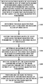
- this disclosure describes a method of decoding video data, the method comprising receiving an encoded block of the video data, the encoded block of the video data having been encoded using an effective quantization parameter and a base quantization parameter, wherein the effective quantization parameter is a function of a quantization parameter offset added to the base quantization parameter, determining the base quantization parameter used to encode the encoded block of the video data, decoding the encoded block of the video data using the base quantization parameter to create a decoded block of video data, determining an estimate of the quantization parameter offset for the decoded block of the video data based on statistics associated with the decoded block of the video data, adding the estimate of the quantization parameter offset to the base quantization parameter to create an estimate of the effective quantization parameter, and performing one or more filtering operations on the decoded block of video data as a function of the estimate of the effective quantization parameter.
- this disclosure describes a method of encoding video data, the method comprising determining a base quantization parameter for a block of the video data, determining a quantization parameter offset for the block of the video data based on statistics associated with the block of the video data, adding the quantization parameter offset to the base quantization parameter to create an effective quantization parameter, and encoding the block of the video data using the effective quantization parameter and the base quantization parameter.
- this disclosure describes an apparatus configured to decode video data, the apparatus comprising a memory configured to store an encoded block of the video data, and one or more processors in communication with the memory, the one or more processors configured to receive the encoded block of the video data, the encoded block of the video data having been encoded using an effective quantization parameter and a base quantization parameter, wherein the effective quantization parameter is a function of a quantization parameter offset added to the base quantization parameter, determine the base quantization parameter used to encode the encoded block of the video data, decode the encoded block of the video data using the base quantization parameter to create a decoded block of video data, determine an estimate of the quantization parameter offset for the decoded block of the video data based on statistics associated with the decoded block of the video data, add the estimate of the quantization parameter offset to the base quantization parameter to create an estimate of the effective quantization parameter, and perform one or more filtering operations on the decoded block of video data as a function of the estimate of the effective quantization parameter.
- this disclosure describes an apparatus configured to encode video data, the apparatus comprising a memory configured to store a block of the video data, and one or more processors in communication with the memory, the one or more processors configured to determine a base quantization parameter for the block of the video data, determine a quantization parameter offset for the block of the video data based on statistics associated with the block of the video data, add the quantization parameter offset to the base quantization parameter to create an effective quantization parameter, and encode the block of the video data using the effective quantization parameter and the base quantization parameter.
- this disclosure describes an apparatus configured to decode video data, the apparatus comprising means for receiving an encoded block of the video data, the encoded block of the video data having been encoded using an effective quantization parameter and a base quantization parameter, wherein the effective quantization parameter is a function of a quantization parameter offset added to the base quantization parameter, means for determining the base quantization parameter used to encode the encoded block of the video data, means for decoding the encoded block of the video data using the base quantization parameter to create a decoded block of video data, means for determining an estimate of the quantization parameter offset for the decoded block of the video data based on statistics associated with the decoded block of the video data, means for adding the estimate of the quantization parameter offset to the base quantization parameter to create an estimate of the effective quantization parameter, and means for performing one or more filtering operations on the decoded block of video data as a function of the estimate of the effective quantization parameter.
- this disclosure describes an apparatus configured to encode video data, the apparatus comprising means for determining a base quantization parameter for a block of the video data, means for determining a quantization parameter offset for the block of the video data based on statistics associated with the block of the video data, means for adding the quantization parameter offset to the base quantization parameter to create an effective quantization parameter, and means for encoding the block of the video data using the effective quantization parameter and the base quantization parameter.
- this disclosure describes a non-transitory computer-readable storage medium storing instructions that, when executed, cause one or more processors to receive the encoded block of the video data, the encoded block of the video data having been encoded using an effective quantization parameter and a base quantization parameter, wherein the effective quantization parameter is a function of a quantization parameter offset added to the base quantization parameter, determine the base quantization parameter used to encode the encoded block of the video data, decode the encoded block of the video data using the base quantization parameter to create a decoded block of video data, determine an estimate of the quantization parameter offset for the decoded block of the video data based on statistics associated with the decoded block of the video data, add the estimate of the quantization parameter offset to the base quantization parameter to create an estimate of the effective quantization parameter, and perform one or more filtering operations on the decoded block of video data as a function of the estimate of the effective quantization parameter.
- this disclosure describes a non-transitory computer-readable storage medium storing instructions that, when executed, cause one or more processors to determine a base quantization parameter for the block of the video data, determine a quantization parameter offset for the block of the video data based on statistics associated with the block of the video data, add the quantization parameter offset to the base quantization parameter to create an effective quantization parameter, and encode the block of the video data using the effective quantization parameter and the base quantization parameter.
- FIG. 1 is a block diagram illustrating an example video encoding and decoding system configured to implement the techniques of the disclosure.
- FIGS. 2A and 2B are conceptual diagrams illustrating an example quadtree binary tree (QTBT) structure, and a corresponding coding tree unit (CTU).
- QTBT quadtree binary tree
- CTU coding tree unit
- FIG. 3 is a conceptual drawing illustrating the concepts of HDR data.
- FIG. 4 is a conceptual diagram illustrating example color gamuts.
- FIG. 5 is a flow diagram illustrating an example of HDR/WCG representation conversion.
- FIG. 6 is a flow diagram illustrating an example of HDR/WCG inverse conversion.
- FIG. 7 is conceptual diagram illustrating example of Electro-optical transfer functions (EOTF) utilized for video data conversion (including SDR and HDR) from perceptually uniform code levels to linear luminance.
- EOTF Electro-optical transfer functions
- FIG. 8 is a block diagram illustrating an example of a video encoder that may implement techniques of this disclosure.
- FIG. 9 is a block diagram illustrating an example quantization unit of a video encoder that may implement techniques of this disclosure
- FIG. 10 is a block diagram illustrating an example of a video decoder that may implement techniques of this disclosure.
- FIG. 11 is a flowchart illustrating an example encoding method.
- FIG. 12 is a flowchart illustrating an example decoding method.
- This disclosure is related to the processing and/or coding of video data with high dynamic range (HDR) and wide color gamut (WCG) representations. More specifically, the techniques of this disclosure include content-adaptive spatially varying quantization without explicit signaling of quantization parameters (e.g., a change in a quantization parameter represented by a deltaQP syntax element) to efficiently compress HDR/WCG video signals.
- quantization parameters e.g., a change in a quantization parameter represented by a deltaQP syntax element
- the techniques and devices described herein may improve compression efficiency of video coding systems utilized for coding HDR and WCG video data.
- the techniques of this disclosure may be used in the context of advanced video codecs, such as extensions of HEVC or next generation video coding standards.
- Video coding standards including hybrid-based video coding standards include ITU-T H.261, ISO/IEC MPEG-1 Visual, ITU-T H.262 or ISO/IEC MPEG-2 Visual, ITU-T H.263, ISO/IEC MPEG-4 Visual and ITU-T H.264 (also known as ISO/IEC MPEG-4 AVC), including its Scalable Video Coding (SVC) and Multi-view Video Coding (MVC) extensions.
- HEVC High Efficiency Video Coding
- JCT-VC Joint Collaboration Team on Video Coding
- VCEG Video Coding Experts Group
- MPEG Motion Picture Experts Group
- HEVC Working Draft 10 (WD10), Bross et al., “High efficiency video coding (HEVC) text specification draft 10 (for FDIS & Last Call),” Joint Collaborative Team on Video Coding (JCT-VC) of ITU-T SG16 WP3 and ISO/IEC JTC1/SC29/WG11, 12th Meeting: Geneva, CH, 14-23 Jan. 2013, JCTVC-L1003v34, is available from http://phenix.int-evry.fr/jct/doc_end_user/documents/12_Geneva/wg11/JCTVC-L1003-v34.zip.
- the finalized HEVC standard is referred to as HEVC version 1.
- the finalized HEVC standard document is published as ITU-T H.265, Series H: Audiovisual and Multimedia Systems, Infrastructure of audiovisual services—Coding of moving video, High efficiency video coding, Telecommunication Standardization Sector of International Telecommunication Union (ITU), April 2013, and another version of the finalized HEVC standard was published in October 2014.
- a copy of the H.265/HEVC specification text may be downloaded from http://www.itu.int/rec/T-REC-H.265-201504-I/en.
- ITU-T VCEG Q6/16
- ISO/IEC MPEG JTC 1/SC 29/WG 11
- JVET Joint Video Exploration Team
- JEM7 Joint Exploration Model 7
- JEM7 Joint Exploration Model 7
- J. Chen E. Alshina
- G. J. Sullivan J.-R. Ohm
- J. Boyce Algorithm description of Joint Exploration Test Model 7 (JEM7),” JVET-G1001, Torino, July 2017.
- VVC Versatile Video Coding
- JVET Joint Video Expert Team
- FIG. 1 is a block diagram illustrating an example video encoding and decoding system 10 that may utilize techniques of this disclosure.
- system 10 includes a source device 12 that provides encoded video data to be decoded at a later time by a destination device 14 .
- source device 12 provides the video data to destination device 14 via a computer-readable medium 16 .
- Source device 12 and destination device 14 may comprise any of a wide range of devices, including desktop computers, notebook (i.e., laptop) computers, tablet computers, set-top boxes, telephone handsets such as so-called “smart” phones, so-called “smart” pads, televisions, cameras, display devices, digital media players, video gaming consoles, video streaming devices, or the like.
- source device 12 and destination device 14 may be equipped for wireless communication.
- Destination device 14 may receive the encoded video data to be decoded via computer-readable medium 16 .
- Computer-readable medium 16 may comprise any type of medium or device capable of moving the encoded video data from source device 12 to destination device 14 .
- computer-readable medium 16 may comprise a communication medium to enable source device 12 to transmit encoded video data directly to destination device 14 in real-time.
- the encoded video data may be modulated according to a communication standard, such as a wired or wireless communication protocol, and transmitted to destination device 14 .
- the communication medium may comprise any wireless or wired communication medium, such as a radio frequency (RF) spectrum or one or more physical transmission lines.
- RF radio frequency
- the communication medium may form part of a packet-based network, such as a local area network, a wide-area network, or a global network such as the Internet.
- the communication medium may include routers, switches, base stations, or any other equipment that may be useful to facilitate communication from source device 12 to destination device 14 .
- computer-readable medium 16 may include non-transitory storage media, such as a hard disk, flash drive, compact disc, digital video disc, Blu-ray disc, or other computer-readable media.
- a network server (not shown) may receive encoded video data from source device 12 and provide the encoded video data to destination device 14 , e.g., via network transmission.
- a computing device of a medium production facility such as a disc stamping facility, may receive encoded video data from source device 12 and produce a disc containing the encoded video data. Therefore, computer-readable medium 16 may be understood to include one or more computer-readable media of various forms, in various examples.
- encoded data may be output from output interface 22 to a storage device.
- encoded data may be accessed from the storage device by input interface.
- the storage device may include any of a variety of distributed or locally accessed data storage media such as a hard drive, Blu-ray discs, DVDs, CD-ROMs, flash memory, volatile or non-volatile memory, or any other suitable digital storage media for storing encoded video data.
- the storage device may correspond to a file server or another intermediate storage device that may store the encoded video generated by source device 12 .
- Destination device 14 may access stored video data from the storage device via streaming or download.
- the file server may be any type of server capable of storing encoded video data and transmitting encoded video data to the destination device 14 .
- Example file servers include a web server (e.g., for a website), an FTP server, network attached storage (NAS) devices, or a local disk drive.
- Destination device 14 may access the encoded video data through any standard data connection, including an Internet connection. This may include a wireless channel (e.g., a Wi-Fi connection), a wired connection (e.g., DSL, cable modem, etc.), or a combination of both that is suitable for accessing encoded video data stored on a file server.
- the transmission of encoded video data from the storage device may be a streaming transmission, a download transmission, or a combination thereof.
- system 10 may be configured to support one-way or two-way video transmission to support applications such as video streaming, video playback, video broadcasting, and/or video telephony.
- source device 12 includes video source 18 , video encoder 20 , and output interface 22 .
- Destination device 14 includes input interface 28 , dynamic range adjustment (DRA) unit 19 , video decoder 30 , and display device 32 .
- DRA unit 19 of source device 12 may be configured to implement the techniques of this disclosure, including signaling and related operations applied to video data in certain color spaces to enable more efficient compression of HDR and WCG video data.
- DRA unit 19 may be separate from video encoder 20 .
- DRA unit 19 may be part of video encoder 20 .
- a source device and a destination device may include other components or arrangements.
- source device 12 may receive video data from an external video source 18 , such as an external camera.
- destination device 14 may interface with an external display device, rather than including an integrated display device.
- the illustrated system 10 of FIG. 1 is merely one example.
- Techniques for processing and coding HDR and WCG video data may be performed by any digital video encoding and/or video decoding device.
- some example techniques of this disclosure may also be performed by a video preprocessor and/or video postprocessor.
- a video preprocessor may be any device configured to process video data before encoding (e.g., before HEVC, VVC, or other encoding).
- a video postprocessor may be any device configured to process video data after decoding (e.g., after HEVC, VVC, or other decoding).
- Source device 12 and destination device 14 are merely examples of such coding devices in which source device 12 generates coded video data for transmission to destination device 14 .
- devices 12 , 14 may operate in a substantially symmetrical manner such that each of devices 12 , 14 include video encoding and decoding components, as well as a video preprocessor and a video postprocessor (e.g., DRA unit 19 and inverse DRA unit 31 , respectively).
- system 10 may support one-way or two-way video transmission between video devices 12 , 14 , e.g., for video streaming, video playback, video broadcasting, or video telephony.
- Video source 18 of source device 12 may include a video capture device, such as a video camera, a video archive containing previously captured video, and/or a video feed interface to receive video from a video content provider.
- video source 18 may generate computer graphics-based data as the source video, or a combination of live video, archived video, and computer-generated video.
- source device 12 and destination device 14 may form so-called camera phones or video phones.
- the techniques described in this disclosure may be applicable to video coding and video processing, in general, and may be applied to wireless and/or wired applications.
- the captured, pre-captured, or computer-generated video may be encoded by video encoder 20 .
- the encoded video information may then be output by output interface 22 onto a computer-readable medium 16 .
- Input interface 28 of destination device 14 receives information from computer-readable medium 16 .
- the information of computer-readable medium 16 may include syntax information defined by video encoder 20 , which is also used by video decoder 30 , that includes syntax elements that describe characteristics and/or processing of blocks and other coded units, e.g., groups of pictures (GOPs).
- Display device 32 displays the decoded video data to a user, and may comprise any of a variety of display devices such as a cathode ray tube (CRT), a liquid crystal display (LCD), a plasma display, an organic light emitting diode (OLED) display, or another type of display device.
- CTR cathode ray tube
- LCD liquid crystal display
- plasma display e.g., a plasma display
- OLED organic light emitting diode
- Video encoder 20 and video decoder 30 each may be implemented as any of a variety of suitable encoder or decoder circuitry, such as one or more microprocessors, digital signal processors (DSPs), application specific integrated circuits (ASICs), field programmable gate arrays (FPGAs), discrete logic, software, hardware, firmware or any combinations thereof.
- DSPs digital signal processors
- ASICs application specific integrated circuits
- FPGAs field programmable gate arrays
- a device may store instructions for the software in a suitable, non-transitory computer-readable medium and execute the instructions in hardware using one or more processors to perform the techniques of this disclosure.
- Each of video encoder 20 and video decoder 30 may be included in one or more encoders or decoders, either of which may be integrated as part of a combined encoder/decoder (CODEC) in a respective device.
- CODEC combined encoder/decoder
- DRA unit 19 and inverse DRA unit 31 each may be implemented as any of a variety of suitable encoder circuitry, such as one or more microprocessors, DSPs, ASICs, FPGAs, discrete logic, software, hardware, firmware or any combinations thereof.
- a device may store instructions for the software in a suitable, non-transitory computer-readable medium and execute the instructions in hardware using one or more processors to perform the techniques of this disclosure.
- video encoder 20 and video decoder 30 operate according to a video compression standard, such as ITU-T H.265/HEVC, VVC, or other next generation video coding standards.
- a video compression standard such as ITU-T H.265/HEVC, VVC, or other next generation video coding standards.
- a video sequence typically includes a series of pictures. Pictures may also be referred to as “frames.”
- a picture may include three sample arrays, denoted S L , S Cb , and S Cr .
- S L is a two-dimensional array (i.e., a block) of luma samples.
- S Cb is a two-dimensional array of Cb chrominance samples.
- S Cr is a two-dimensional array of Cr chrominance samples.
- Chrominance samples may also be referred to herein as “chroma” samples.
- a picture may be monochrome and may only include an array of luma samples.
- Video encoder 20 may generate a set of coding tree units (CTUs).
- Each of the CTUs may comprise a coding tree block of luma samples, two corresponding coding tree blocks of chroma samples, and syntax structures used to code the samples of the coding tree blocks.
- a CTU may comprise a single coding tree block and syntax structures used to code the samples of the coding tree block.
- a coding tree block may be an N ⁇ N block of samples.
- a CTU may also be referred to as a “tree block” or a “largest coding unit” (LCU).
- the CTUs of HEVC may be broadly analogous to the macroblocks of other video coding standards, such as H.264/AVC.
- a CTU is not necessarily limited to a particular size and may include one or more coding units (CUs).
- a slice may include an integer number of CTUs ordered consecutively in the raster scan.
- video unit or “video block” to refer to one or more blocks of samples and syntax structures used to code samples of the one or more blocks of samples.
- Example types of video units may include CTUs, CUs, PUs, transform units (TUs) in HEVC, or macroblocks, macroblock partitions, and so on in other video coding standards.
- video encoder 20 may recursively perform quad-tree partitioning on the coding tree blocks of a CTU to divide the coding tree blocks into coding blocks, hence the name “coding tree units.”
- a coding block is an N ⁇ N block of samples.
- a CU may comprise a coding block of luma samples and two corresponding coding blocks of chroma samples of a picture that has a luma sample array, a Cb sample array and a Cr sample array, and syntax structures used to code the samples of the coding blocks.
- a CU may comprise a single coding block and syntax structures used to code the samples of the coding block.
- Video encoder 20 may partition a coding block of a CU into one or more prediction blocks.
- a prediction block may be a rectangular (i.e., square or non-square) block of samples on which the same prediction is applied.
- a prediction unit (PU) of a CU may comprise a prediction block of luma samples, two corresponding prediction blocks of chroma samples of a picture, and syntax structures used to predict the prediction block samples.
- a PU may comprise a single prediction block and syntax structures used to predict the prediction block samples.
- Video encoder 20 may generate predictive luma, Cb and Cr blocks for luma, Cb and Cr prediction blocks of each PU of the CU.
- a quadtree binary tree (QTBT) partitioning structure may be used.
- the QTBT structure removes the concepts of multiple partitions types. That is, the QTBT structure removes the separation of the CU, PU, and TU concepts, and supports more flexibility for CU partition shapes.
- a CU can have either a square or rectangular shape.
- a CU is first partition by a quadtree structure.
- the quadtree leaf nodes are further partitioned by a binary tree structure.
- a CU sometimes consists of coding blocks (CBs) of different color components.
- CBs coding blocks
- one CU contains one luma CB and two chroma CBs in the case of P and B slices of the 4:2:0 chroma format and sometimes consists of a CB of a single component.
- one CU contains only one luma CB or just two chroma CBs in the case of I slices.
- video encoder 20 and video decoder 30 may be configured to operate according to JEM/VVC.
- a video coder (such as video encoder 20 ) partitions a picture into a plurality of CU.
- An example QTBT structure of JEM includes two levels: a first level partitioned according to quadtree partitioning, and a second level partitioned according to binary tree partitioning.
- a root node of the QTBT structure corresponds to a CTU.
- Leaf nodes of the binary trees correspond to coding units (CUs).
- video encoder 20 and video decoder 30 may use a single QTBT structure to represent each of the luminance and chrominance components, while in other examples, video encoder 20 and video decoder 30 may use two or more QTBT structures, such as one QTBT structure for the luminance component and another QTBT structure for both chrominance components (or two QTBT structures for respective chrominance components).
- Video encoder 20 and video decoder 30 may be configured to use quadtree partitioning per HEVC, QTBT partitioning according to JEM/VVC, or other partitioning structures.
- quadtree partitioning per HEVC
- QTBT partitioning according to JEM/VVC
- JEM/VVC Joint Element-to-VVC
- the description of the techniques of this disclosure is presented with respect to QTBT partitioning.
- the techniques of this disclosure may also be applied to video coders configured to use quadtree partitioning, or other types of partitioning as well.
- FIGS. 2A and 2B are conceptual diagram illustrating an example quadtree binary tree (QTBT) structure 130 , and a corresponding coding tree unit (CTU) 132 .
- the solid lines represent quadtree splitting, and dotted lines indicate binary tree splitting.
- each split (i.e., non-leaf) node of the binary tree one flag is signaled to indicate which splitting type (i.e., horizontal or vertical) is used, where 0 indicates horizontal splitting and 1 indicates vertical splitting in this example.
- splitting type i.e., horizontal or vertical
- video encoder 20 may encode, and video decoder 30 may decode, syntax elements (such as splitting information) for a region tree level of QTBT structure 130 (i.e., the solid lines) and syntax elements (such as splitting information) for a prediction tree level of QTBT structure 130 (i.e., the dashed lines).
- Video encoder 20 may encode, and video decoder 30 may decode, video data, such as prediction and transform data, for CUs represented by terminal leaf nodes of QTBT structure 130 .
- CTU 132 of FIG. 2B may be associated with parameters defining sizes of blocks corresponding to nodes of QTBT structure 130 at the first and second levels. These parameters may include a CTU size (representing a size of CTU 132 in samples), a minimum quadtree size (MinQTSize, representing a minimum allowed quadtree leaf node size), a maximum binary tree size (MaxBTSize, representing a maximum allowed binary tree root node size), a maximum binary tree depth (MaxBTDepth, representing a maximum allowed binary tree depth), and a minimum binary tree size (MinBTSize, representing the minimum allowed binary tree leaf node size).
- CTU size representing a size of CTU 132 in samples
- MinQTSize representing a minimum allowed quadtree leaf node size
- MaxBTSize representing a maximum binary tree root node size
- MaxBTDepth representing a maximum allowed binary tree depth
- MinBTSize representing the minimum allowed binary tree leaf node size
- the root node of a QTBT structure corresponding to a CTU may have four child nodes at the first level of the QTBT structure, each of which may be partitioned according to quadtree partitioning. That is, nodes of the first level are either leaf nodes (having no child nodes) or have four child nodes.
- the example of QTBT structure 130 represents such nodes as including the parent node and child nodes having solid lines for branches. If a node of the first level are not larger than the maximum allowed binary tree root node size (MaxBTSize), then the node can be further partitioned by respective binary trees.
- MaxBTSize maximum allowed binary tree root node size
- the binary tree splitting of one node can be iterated until the nodes resulting from the split reach the minimum allowed binary tree leaf node size (MinBTSize) or the maximum allowed binary tree depth (MaxBTDepth).
- MinBTSize minimum allowed binary tree leaf node size
- MaxBTDepth maximum allowed binary tree depth
- the example of QTBT structure 130 represents such nodes as having dashed lines for branches.
- the binary tree leaf node is referred to as a coding unit (CU), which is used for prediction (e.g., intra-picture or inter-picture prediction) and transform, without any further partitioning.
- CUs may also be referred to as “video blocks” or “blocks.”
- the CTU size is set as 128 ⁇ 128 (luma samples and two corresponding 64 ⁇ 64 chroma samples), the MinQTSize is set as 16 ⁇ 16, the MaxBTSize is set as 64 ⁇ 64, the MinBTSize (for both width and height) is set as 4, and the MaxBTDepth is set as 4.
- the quadtree partitioning is applied to the CTU first to generate quad-tree leaf nodes.
- the quadtree leaf nodes may have a size from 16 ⁇ 16 (i.e., the MinQTSize) to 128 ⁇ 128 (i.e., the CTU size).
- leaf quadtree node If the leaf quadtree node is 128 ⁇ 128, then the node will not be further split by the binary tree, since the size exceeds the MaxBTSize (i.e., 64 ⁇ 64, in this example). Otherwise, the leaf quadtree node will be further partitioned by the binary tree. Therefore, the quadtree leaf node is also the root node for the binary tree and has the binary tree depth as 0. When the binary tree depth reaches MaxBTDepth (4, in this example), no further splitting is permitted. The binary tree node having width equal to MinBTSize (4, in this example) implies no further horizontal splitting is permitted. Similarly, a binary tree node having a height equal to MinBTSize implies no further vertical splitting is permitted for that binary tree node. As noted above, leaf nodes of the binary tree are referred to as CUs, and are further processed according to prediction and transform without further partitioning.
- Video encoder 20 may use intra prediction or inter prediction to generate the predictive blocks for a PU. If video encoder 20 uses intra prediction to generate the predictive blocks of a PU, video encoder 20 may generate the predictive blocks of the PU based on decoded samples of the picture associated with the PU.
- video encoder 20 may generate the predictive blocks of the PU based on decoded samples of one or more pictures other than the picture associated with the PU.
- Inter prediction may be uni-directional inter prediction (i.e., uni-prediction) or bi-directional inter prediction (i.e., bi-prediction).
- video encoder 20 may generate a first reference picture list (RefPicList0) and a second reference picture list (RefPicList1) for a current slice.
- Each of the reference picture lists may include one or more reference pictures.
- video encoder 20 may search the reference pictures in either or both RefPicList0 and RefPicList1 to determine a reference location within a reference picture.
- video encoder 20 may generate, based at least in part on samples corresponding to the reference location, the predictive sample blocks for the PU.
- video encoder 20 may generate a single motion vector that indicates a spatial displacement between a prediction block of the PU and the reference location.
- a motion vector may include a horizontal component specifying a horizontal displacement between the prediction block of the PU and the reference location and may include a vertical component specifying a vertical displacement between the prediction block of the PU and the reference location.
- video encoder 20 may determine a first reference location in a reference picture in RefPicList0 and a second reference location in a reference picture in RefPicList1. Video encoder 20 may then generate, based at least in part on samples corresponding to the first and second reference locations, the predictive blocks for the PU. Moreover, when using bi-prediction to encode the PU, video encoder 20 may generate a first motion indicating a spatial displacement between a sample block of the PU and the first reference location and a second motion indicating a spatial displacement between the prediction block of the PU and the second reference location.
- JEM/VVC also provides an affine motion compensation mode, which may be considered an inter-prediction mode.
- affine motion compensation mode video encoder 20 may determine two or more motion vectors that represent non-translational motion, such as zoom in or out, rotation, perspective motion, or other irregular motion types.
- video encoder 20 may generate a luma residual block for the CU.
- Each sample in the CU's luma residual block indicates a difference between a luma sample in one of the CU's predictive luma blocks and a corresponding sample in the CU's original luma coding block.
- video encoder 20 may generate a Cb residual block for the CU.
- Each sample in the CU's Cb residual block may indicate a difference between a Cb sample in one of the CU's predictive Cb blocks and a corresponding sample in the CU's original Cb coding block.
- Video encoder 20 may also generate a Cr residual block for the CU.
- Each sample in the CU's Cr residual block may indicate a difference between a Cr sample in one of the CU's predictive Cr blocks and a corresponding sample in the CU's original Cr coding block.
- video encoder 20 may use quad-tree partitioning to decompose the luma, Cb and, Cr residual blocks of a CU into one or more luma, Cb, and Cr transform blocks.
- a transform block may be a rectangular block of samples on which the same transform is applied.
- a transform unit (TU) of a CU may comprise a transform block of luma samples, two corresponding transform blocks of chroma samples, and syntax structures used to transform the transform block samples.
- a TU may comprise a single transform block and syntax structures used to transform the transform block samples.
- each TU of a CU may be associated with a luma transform block, a Cb transform block, and a Cr transform block.
- the luma transform block associated with the TU may be a sub-block of the CU's luma residual block.
- the Cb transform block may be a sub-block of the CU's Cb residual block.
- the Cr transform block may be a sub-block of the CU's Cr residual block.
- Video encoder 20 may apply one or more transforms to a luma transform block of a TU to generate a luma coefficient block for the TU.
- a coefficient block may be a two-dimensional array of transform coefficients.
- a transform coefficient may be a scalar quantity.
- Video encoder 20 may apply one or more transforms to a Cb transform block of a TU to generate a Cb coefficient block for the TU.
- Video encoder 20 may apply one or more transforms to a Cr transform block of a TU to generate a Cr coefficient block for the TU.
- video encoder 20 may quantize the coefficient block. Quantization generally refers to a process in which transform coefficients are quantized to possibly reduce the amount of data used to represent the transform coefficients, providing further compression. Furthermore, video encoder 20 may inverse quantize transform coefficients and apply an inverse transform to the transform coefficients in order to reconstruct transform blocks of TUs of CUs of a picture. Video encoder 20 may use the reconstructed transform blocks of TUs of a CU and the predictive blocks of PUs of the CU to reconstruct coding blocks of the CU.
- video encoder 20 may reconstruct the picture.
- Video encoder 20 may store reconstructed pictures in a decoded picture buffer (DPB).
- DPB decoded picture buffer
- Video encoder 20 may use reconstructed pictures in the DPB for inter prediction and intra prediction.
- video encoder 20 may entropy encode syntax elements that indicate the quantized transform coefficients. For example, video encoder 20 may perform Context-Adaptive Binary Arithmetic Coding (CABAC) on the syntax elements indicating the quantized transform coefficients. Video encoder 20 may output the entropy-encoded syntax elements in a bitstream.
- CABAC Context-Adaptive Binary Arithmetic Coding
- Video encoder 20 may output a bitstream that includes a sequence of bits that forms a representation of coded pictures and associated data.
- the bitstream may comprise a sequence of network abstraction layer (NAL) units.
- NAL network abstraction layer
- Each of the NAL units includes a NAL unit header and encapsulates a raw byte sequence payload (RBSP).
- the NAL unit header may include a syntax element that indicates a NAL unit type code.
- the NAL unit type code specified by the NAL unit header of a NAL unit indicates the type of the NAL unit.
- a RBSP may be a syntax structure containing an integer number of bytes that is encapsulated within a NAL unit. In some instances, an RBSP includes zero bits.
- NAL units may encapsulate different types of RBSPs.
- a first type of NAL unit may encapsulate a RBSP for a picture parameter set (PPS)
- a second type of NAL unit may encapsulate a RBSP for a coded slice
- a third type of NAL unit may encapsulate a RBSP for Supplemental Enhancement Information (SEI), and so on.
- SEI Supplemental Enhancement Information
- a PPS is a syntax structure that may contain syntax elements that apply to zero or more entire coded pictures.
- NAL units that encapsulate RBSPs for video coding data (as opposed to RBSPs for parameter sets and SEI messages) may be referred to as video coding layer (VCL) NAL units.
- VCL video coding layer
- a NAL unit that encapsulates a coded slice may be referred to herein as a coded slice NAL unit.
- a RBSP for a coded slice may include a slice header
- Video decoder 30 may receive a bitstream.
- video decoder 30 may parse the bitstream to decode syntax elements from the bitstream.
- Video decoder 30 may reconstruct the pictures of the video data based at least in part on the syntax elements decoded from the bitstream.
- the process to reconstruct the video data may be generally reciprocal to the process performed by video encoder 20 .
- video decoder 30 may use motion vectors of PUs to determine predictive blocks for the PUs of a current CU.
- Video decoder 30 may use a motion vector or motion vectors of PUs to generate predictive blocks for the PUs.
- video decoder 30 may inverse quantize coefficient blocks associated with TUs of the current CU. Video decoder 30 may perform inverse transforms on the coefficient blocks to reconstruct transform blocks associated with the TUs of the current CU. Video decoder 30 may reconstruct the coding blocks of the current CU by adding the samples of the predictive sample blocks for PUs of the current CU to corresponding samples of the transform blocks of the TUs of the current CU. By reconstructing the coding blocks for each CU of a picture, video decoder 30 may reconstruct the picture. Video decoder 30 may store decoded pictures in a decoded picture buffer for output and/or for use in decoding other pictures.
- Next generation video applications are anticipated to operate with video data representing captured scenery with HDR and/or (WCG.
- Parameters of the utilized dynamic range and color gamut are two independent attributes of video content, and their specification for purposes of digital television and multimedia services are defined by several international standards.
- ITU-R Rec. BT.709 “Parameter values for the HDTV standards for production and international programme exchange,” defines parameters for HDTV (high definition television), such as standard dynamic range (SDR) and standard color gamut
- SDR standard dynamic range
- ITU-R Rec. BT.2020 “Parameter values for ultra-high definition television systems for production and international programme exchange,” specifies UHDTV (ultra-high definition television) parameters, such as HDR and WCG.
- SDOs standards developing organization
- Dynamic range is typically defined as the ratio between the minimum and maximum brightness (e.g., luminance) of the video signal. Dynamic range may also be measured in terms of ‘f-stop,’ where one f-stop corresponds to a doubling of a signal's dynamic range.
- HDR content is content that features brightness variation with more than 16 f-stops. In some terms, levels between 10 and 16 f-stops are considered as intermediate dynamic range but in other definitions, are considered HDR.
- HDR video content may be any video content that has a higher dynamic range than traditionally used video content with a standard dynamic range (e.g., video content as specified by ITU-R Rec. BT.709).
- the human visual system is capable for perceiving much larger dynamic ranges than SDR content and HDR content.
- the HVS includes an adaptation mechanism to narrow the dynamic range of the HVS to a so-called simultaneous range.
- the width of the simultaneous range may be dependent on current lighting conditions (e.g., current brightness).
- Visualization of dynamic range provided by SDR of HDTV, expected HDR of UHDTV and HVS dynamic range is shown in FIG. 3 , although the exact range may vary based on each individual and display.
- Some example video applications and services are regulated by ITU Rec.709 and provide SDR, typically supporting a range of brightness (e.g., luminance) of around 0.1 to 100 candelas (cd) per m2 (often referred to as “nits”), leading to less than 10 f-stops.
- Some example next generation video services are expected to provide dynamic range of up to 16 f-stops. Although detailed specifications for such content are currently under development, some initial parameters have been specified in SMPTE-2084 and ITU-R Rec. 2020.
- FIG. 4 is a conceptual diagram showing an SDR color gamut (triangle 100 based on the BT.709 color primaries), and the wider color gamut that for UHDTV (triangle 102 based on the BT.2020 color primaries).
- FIG. 3 also depicts the so-called spectrum locus (delimited by the tongue-shaped area 104 ), representing the limits of the natural colors.
- moving from BT.709 (triangle 100 ) to BT.2020 (triangle 102 ) color primaries aims to provide UHDTV services with about 70% more colors.
- D65 specifies an example white color for the BT.709 and/or BT.2020 specifications.
- RGB color space parameters Color White point Primary colors space x w y w x R y R x G y G x B y B DCI- 0.314 0.351 0.680 0.320 0.265 0.690 0.150 0.060 P3 ITU-R 0.3127 0.3290 0.64 0.33 0.30 0.60 0.15 0.06 BT.709 ITU-R 0.3127 0.3290 0.708 0.292 0.170 0.797 0.131 0.046 BT.2020
- a color gamut may be defined by the X and Y values of a white point, and by the X and Y values of the primary colors (e.g., red (R), green (G), and blue (B).
- the X and Y values represent the chromaticity (X) and the brightness (Y) of the colors, as is defined by the CIE 1931 color space.
- the CIE 1931 color space defines the links between pure colors (e.g., in terms of wavelengths) and how the human eye perceives such colors.
- HDR/WCG video data is typically acquired and stored at a very high precision per component (even floating point), with the 4:4:4 chroma sub-sampling format and a very wide color space (e.g., CIE XYZ).
- This representation targets high precision and is almost mathematically lossless.
- a format for storing HDR/WCG video data may include a lot of redundancies and may not be optimal for compression purposes.
- a lower precision format with HVS-based assumptions is typically utilized for state-of-the-art video applications.
- Linear RGB data 110 may be HDR/WCG video data and may be stored in a floating-point representation.
- Linear RGB data 110 may be compacted using a non-linear transfer function (TF) 112 for dynamic range compacting.
- Transfer function 112 may compact linear RGB data 110 using any number of non-linear transfer functions, e.g., the PQ TF as defined in SMPTE-2084.
- color conversion process 114 converts the compacted data into a more compact or robust color space (e.g., a YUV or YCrCb color space) that is more suitable for compression by a hybrid video encoder.
- This data is then quantized using a floating-to-integer representation quantization unit 116 to produce converted HDR′ data 118 .
- HDR′ data 118 is in an integer representation.
- the HDR′ data is now in a format more suitable for compression by a hybrid video encoder (e.g., video encoder 20 applying HEVC techniques).
- the order of the processes depicted in FIG. 5 is given as an example, and may vary in other applications. For example, color conversion may precede the TF process. In some examples, additional processing, e.g. spatial subsampling, may be applied to color components.
- Converted HDR′ data 120 may be obtained at destination device 14 through decoding video data using a hybrid video decoder (e.g., video decoder 30 applying HEVC techniques). HDR′ data 120 may then be inverse quantized by inverse quantization unit 122 . Then an inverse color conversion process 124 may be applied to the inverse quantized HDR′ data.
- the inverse color conversion process 124 may be the inverse of color conversion process 114 .
- the inverse color conversion process 124 may convert the HDR′ data from a YCrCb format back to an RGB format.
- inverse transfer function 126 may be applied to the data to add back the dynamic range that was compacted by transfer function 112 to recreate the linear RGB data 128 .
- mapping the digital values appearing in an image container to and from optical energy may involve the use of a “transfer function.”
- a transfer function is applied to data (e.g., HDR/WCG video data) to compact the dynamic range of the data.
- data e.g., HDR/WCG video data
- the transfer function may be a one-dimensional (1D) non-linear function and may reflect the inverse of an electro-optical transfer function (EOTF) of the end-user display, e.g., as specified for SDR in ITU-R BT. 1886 (also defined in Rec. 709).
- EOTF electro-optical transfer function
- the transfer function may approximate the HVS perception to brightness changes, e.g., the PQ transfer function specified in SMPTE-2084 for HDR.
- the inverse process of the OETF is the EOTF (electro-optical transfer function), which maps the code levels back to luminance.
- FIG. 7 shows several examples of non-linear transfer function used to compact the dynamic range of certain color containers. The transfer functions may also be applied to each R, G and B component separately.
- SMPTE has recently standardized a new transfer function called SMPTE ST-2084.
- R ′ PQ_TF ⁇ ( max ⁇ ( 0 , min ⁇ ( R ⁇ / ⁇ NORM , 1 ) ) )
- G ′ PQ_TF ⁇ ( max ⁇ ( 0 , min ⁇ ( G ⁇ / ⁇ NORM , 1 ) ) )
- an EOTF is defined as a function with a floating-point accuracy, thus no error is introduced to a signal with this non-linearity if an inverse TF (so-called OETF) is applied.
- An inverse TF (OETF) specified in ST-2084 is defined as inversePQ function:
- R 10000 * inversePQ_TF ⁇ ( R ′ )
- G 10000 * inversePQ_TF ⁇ ( G ′ )
- EOTF and OETF is a subject of very active research and standardization, and TF utilized in some video coding systems may be different from ST-2084.
- the terms “signal value” or “color value” may be used to describe a luminance level corresponding to the value of a specific color component (such as R, G, B, or Y) for an image element.
- the signal value is typically representative of a linear light level (luminance value).
- code level or “digital code value” may refer to a digital representation of an image signal value. Typically, such a digital representation is representative of a nonlinear signal value.
- An EOTF represents the relationship between the nonlinear signal values provided to a display device (e.g., display device 32 ) and the linear color values produced by the display device.
- RGB data is typically utilized as the input color space, since RGB is the type of data that is typically produced by image capturing sensors.
- the RGB color space has high redundancy among its components and is not optimal for compact representation.
- RGB components are typically converted (e.g., a color transform is performed) to a more uncorrelated color space that is more suitable for compression, e.g., YCbCr.
- a YCbCr color space separates the brightness in the form of luminance (Y) and color information (CrCb) in different less correlated components.
- a robust representation may refer to a color space featuring higher levels of error resilience when compressed at a constrained bitrate.
- a typically used color space is YCbCr, as specified in ITU-R BT.709.
- the YCbCr color space in the BT.709 standard specifies the following conversion process from R′G′B′ to Y′CbCr (non-constant luminance representation):
- ⁇ Y ′ 0.2126 * R ′ + 0.7152 * G ′ + 0.0722 * B ′ b .
- ⁇ Cb B ′ - Y ′ 1.8556 c .
- ⁇ Cr R ′ - Y ′ 1.5748
- the ITU-R BT.2020 standard specifies the following conversion process from R′G′B′ to Y′CbCr (non-constant luminance representation):
- ⁇ Y ′ 0.2627 * R ′ + 0.6780 * G ′ + 0.0593 * B ′ b .
- ⁇ Cb B ′ - Y ′ 1.8814 c .
- ⁇ Cr R ′ - Y ′ 1.4746
- input data in a target color space may be still represented at high bit-depth (e.g. floating-point accuracy).
- the high bit-depth data may be converted to a target bit-depth, for example, using a quantization process.
- JND Just-Noticeable Difference
- a JND is the amount something (e.g., video data) must be changed in order for a difference to be noticeable (e.g., by the HVS).
- Data represented with 10 bits accuracy can be further coded with most of the state-of-the-art video coding solutions.
- This quantization is an element of lossy coding and is a source of inaccuracy introduced to converted data.
- Example of such quantization applied to code words in target color space (in this example YCbCr) is shown below.
- Input values YCbCr represented in floating point accuracy are converted into a signal of fixed bit-depth BitDepthY for the Y value and BitDepthC for the chroma values (Cb, Cr).
- D Y′ Clip1 Y (Round((1«(BitDepth Y ⁇ 8))*(219* Y′+ 16)))
- D Cb Clip1 C (Round((1«(BitDepth C ⁇ 8))*(224* Cb+ 128)))
- D Cr Clip1 C (Round((1 «(BitDepth C ⁇ 8))*(224* Cr+ 128))))
- RDOQ rate distortion optimized quantizer
- RDOQ Rate Distortion Optimized Quantization
- the purpose of RDOQ is to find the optimal or most optimal set of quantized transform coefficients representing a residual data in an encoded block.
- the RDOQ calculates the image distortion (introduced by quantization of transform coefficients) in an encoded block and a number of bits needed to encode the corresponding quantized transform coefficient. Based on these two values, the encoder chooses a better coefficient value by calculating RD cost.
- the RDOQ in the encoder may include 3 stages: quantization of transform coefficients, elimination of coefficient groups (CG), and selection of the last non-zero coefficient.
- the video encoder performs produce transform coefficients by uniform quantizer without dead zone, which results in Level value calculation for the current transform coefficient.
- the video encoder considers two additional magnitudes of this quantized coefficient: Level-1 and 0. For every one of these 3 options ⁇ Level, Level-1, 0 ⁇ , the video encoder calculates the RD cost of encoding the coefficient with the selected magnitude and chooses the one with the lowest RD cost.
- some RDOQ implementations may consider nullifying a transform coefficient group entirely, or reducing the size of the signaled transform coefficient group by reducing the position of the last signaled coefficient for each of the groups.
- inverse scalar quantization is applied to quantized transform coefficients derived from the syntax elements of the bitstream.
- JND Just-Noticeable Difference
- a quantization scheme that is uniform over the dynamic range of luma values (e.g., uniform over all codeword values for luma) would introduce quantization error with different merit of human perception over the signal fragments (partitions of the dynamic range).
- Such impact on signals may be interpreted by a viewer as a processing system with a non-uniform quantization, which results in unequal signal-to-noise ratios within processed data range.
- NCL YCbCr Non Constant Luminance
- ITU-R Rec. BT.2020 ITU-R Rec. BT.2020
- ST-2084 transfer function As illustrated in Table 2, NCL YCbCR color spaces allocates a significantly larger amount of codewords for the low intensity values of the signal, e.g., 30% of codewords represent linear light samples ⁇ 10 nits, whereas high intensity samples (high brightness) are represented with a much smaller amount of codewords, e.g., 25% of codewords are allocated for linear light in the range 1000-10000 nits.
- a video coding system e.g., H.265/HEVC, featuring uniform quantization for all ranges of the data would introduce much more severe coding artifacts to the high intensity samples (bright region of the signal), where distortion introduced to low intensity samples (dark region of the same signal) would be far below noticeable difference.
- the re-distribution introduces linearization of perceived distortion (signal-to-noise ratio) within a dynamic range of the data through a Dynamical Range Adjustment. This redistribution was found to improve visual quality under the bitrate constrains.
- an inverse process is applied to the data after video decoding.
- the proposed spatially varying quantization scheme being introduced at the encoding stage was found to be able to improve visually perceived signal-to-quantization noise ratio for coded video signal in ST 2084/BT.2020 representation.
- One of the drawback of this approach is a block-based granularity of QP adaptation.
- Typically utilized block sizes selected at the encoder side for compression are derived through a rate distortion optimization process, and may not represent dynamic range properties of the video signal, thus the selected QP settings will be sub-optimal for the signal inside of the block. This problem may become even more important for the next generation video coding systems that tend to employ prediction and transform block sizes of larger dimensions.
- Another aspect of this design is a need for signaling of QP adaptation parameters to the decoder side for inverse dequantization. Additionally, spatial adaptation of quantization parameters at the encoder side increases the complexity of encoding optimization and may interfere with rate control algorithms.
- IDSQ Intensity Dependent Spatial Quantization
- This disclosure describes several video coding and processing techniques that may be applied in the video coding loop (e.g., during the video encoding and/or decoding process and not in pre- or post-processing) of a video coding system.
- the techniques of this disclosure include encoder side (e.g., video encoder 20 ) algorithms with content-adaptive spatially varying quantization without explicit signaling of quantization parameters (e.g., a change in a quantization parameter represented by a deltaQP syntax element) to more efficiently compress HDR/WCG video signals.
- the techniques of this disclosure also include decoder side (e.g., video decoder 30 ) operations which improve performance of video decoding tools that use quantization parameters information. Examples of such decoding tools can include deblocking filters, bilateral filters, adaptive loop filters, or other video coding tools that use quantization information as an input.
- Video encoder 20 and/or video decoder 30 may be configured to perform one or more of the following techniques independently, or in any combination with others.
- video encoder 20 may be configured to perform a multi-stage quantization process for each block of video data in a picture of video data.
- the techniques described below may be applied to both luma and chroma components of the video data.
- Video decoder may be configured to perform quantization using a base quantization parameter (QPb) value. That is, the QPb value is applied uniformly across all blocks.
- QPb base quantization parameter
- video encoder 20 may further be configured to utilize a content-dependent QP offset as a deviation from the QPb value. That is, for each block of video data, or for a group of blocks of video data, video encoder 20 may further determine a QP offset that is based on the content of the block of groups of blocks.
- video encoder 20 may account for a rate distortion optimized (RDO) selection of a quantization level LevelX, which is produced by an effectively different quantization parameter (QPe).
- QPe may be referred to as an effective quantization parameter.
- QPe is the QP offset (deltaQP) plus the base QPb value.
- video encoder 20 may be configured to derive the value of deltaQP for block Cb using a function of the average of the sample values (e.g., luma or chroma values) of the block Cb.
- video encoder 20 may use other functions of the sample value values of block Cb to determine the value of deltaQP.
- video encoder 20 may determine the value of deltaQP using a second order operation (e.g., variance) on the sample values of block Cb.
- video encoder 20 may determine the value of deltaQP using a function of the sample values of block Cb and values of one or more samples of neighboring blocks.
- video encoder 20 may be configured to quantize residual values of block Cb with both the QPb value and the QPe value.
- the residual data r(Cb) derived for currently coded block Cb is coded with quantization parameter QPb.
- the distortion introduced to the residual is first produced with quantization parameter QPe, resulting in transform quantization coefficients tq(Cb). Since QPe may vary from block to block, video encoder 20 may adjust for the varying JND threshold present in some color representations, and provide for a non-uniform quantization.
- video decoder 30 does not use effective quantization parameter QPe when reconstructing residual values for the block.
- the distortion introduced by video encoder 20 when applying QPe during encoding remains in the residuals, thus improving uneven JND threshold issues with certain color spaces, as discussed above.
- other decoding tools e.g., in-loop filtering, entropy decoding, etc.
- QP parameters provided by the bitstream for attenuating its operation may be adjusted to improve their performance.
- video decoder 30 may be configured to derive an estimate of the effective quantization parameter QPe from statistics of the decoded samples d(Cb) and other parameters of bitstream. In this way, bit overhead is saved, as block-by-block values of QPe are not signaled in the bitstream.
- FIG. 8 is a block diagram illustrating an example of video encoder 20 that may implement the techniques of this disclosure.
- video encoder 20 receives a current video block of video data within a video frame to be encoded.
- the video data received by video encoder 20 may HDR and/or WCG video data.
- video encoder 20 includes mode select unit 40 , video data memory 41 , DPB 64 , summer 50 , transform processing unit 52 , quantization unit 54 , and entropy encoding unit 56 .
- Mode select unit 40 includes motion compensation unit 44 , motion estimation unit 42 , intra prediction processing unit 46 , and partition unit 48 .
- video encoder 20 also includes inverse quantization unit 58 , inverse transform processing unit 60 , and summer 62 .
- a deblocking filter (not shown in FIG. 8 ) may also be included to filter block boundaries to remove blockiness artifacts from reconstructed video. If desired, the deblocking filter would typically filter the output of summer 62 . Additional filters (in loop or post loop) may also be used in addition to the deblocking filter. Such filters are not shown for brevity, but if desired, may filter the output of summer 50 (as an in-loop filter).
- Video data memory 41 may store video data to be encoded by the components of video encoder 20 .
- the video data stored in video data memory 41 may be obtained, for example, from video source 18 .
- Decoded picture buffer 64 may be a reference picture memory that stores reference video data for use in encoding video data by video encoder 20 , e.g., in intra- or inter-coding modes.
- Video data memory 41 and decoded picture buffer 64 may be formed by any of a variety of memory devices, such as dynamic random access memory (DRAM), including synchronous DRAM (SDRAM), magnetoresistive RAM (MRAM), resistive RAM (RRAM), or other types of memory devices.
- Video data memory 41 and decoded picture buffer 64 may be provided by the same memory device or separate memory devices.
- video data memory 41 may be on-chip with other components of video encoder 20 , or off-chip relative to those components.
- video encoder 20 receives a video frame or slice to be coded.
- the frame or slice may be divided into multiple video blocks.
- Motion estimation unit 42 and motion compensation unit 44 perform inter-predictive coding of the received video block relative to one or more blocks in one or more reference frames to provide temporal prediction.
- Intra prediction processing unit 46 may alternatively perform intra-predictive coding of the received video block relative to one or more neighboring blocks in the same frame or slice as the block to be coded to provide spatial prediction.
- Video encoder 20 may perform multiple coding passes, e.g., to select an appropriate coding mode for each block of video data.
- partition unit 48 may partition blocks of video data into sub-blocks, based on evaluation of previous partitioning schemes in previous coding passes. For example, partition unit 48 may initially partition a frame or slice into LCUs, and partition each of the LCUs into sub-CUs based on rate-distortion analysis (e.g., rate-distortion optimization). Mode select unit 40 may further produce a quadtree data structure indicative of partitioning of an LCU into sub-CUs. Leaf-node CUs of the quadtree may include one or more PUs and one or more TUs. In other examples, partition unit 48 may partition the input video data according to a QTBT partitioning structure.
- Mode select unit 40 may select one of the coding modes, intra or inter, e.g., based on error results, and provides the resulting intra- or inter-coded block to summer 50 to generate residual block data and to summer 62 to reconstruct the encoded block for use as a reference frame. Mode select unit 40 also provides syntax elements, such as motion vectors, intra-mode indicators, partition information, and other such syntax information, to entropy encoding unit 56 .
- Motion estimation unit 42 and motion compensation unit 44 may be highly integrated, but are illustrated separately for conceptual purposes.
- Motion estimation performed by motion estimation unit 42 , is the process of generating motion vectors, which estimate motion for video blocks.
- a motion vector for example, may indicate the displacement of a PU of a video block within a current video frame or picture relative to a predictive block within a reference picture (or other coded unit) relative to the current block being coded within the current picture (or other coded unit).
- a predictive block is a block that is found to closely match the block to be coded, in terms of pixel difference, which may be determined by sum of absolute difference (SAD), sum of square difference (SSD), or other difference metrics.
- video encoder 20 may calculate values for sub-integer pixel positions of reference pictures stored in decoded picture buffer 64 .
- video encoder 20 may interpolate values of one-quarter pixel positions, one-eighth pixel positions, or other fractional pixel positions of the reference picture. Therefore, motion estimation unit 42 may perform a motion search relative to the full pixel positions and fractional pixel positions and output a motion vector with fractional pixel precision.
- Motion estimation unit 42 calculates a motion vector for a PU of a video block in an inter-coded slice by comparing the position of the PU to the position of a predictive block of a reference picture.
- the reference picture may be selected from a first reference picture list (List 0) or a second reference picture list (List 1), each of which identify one or more reference pictures stored in decoded picture buffer 64 .
- Motion estimation unit 42 sends the calculated motion vector to entropy encoding unit 56 and motion compensation unit 44 .
- Motion compensation performed by motion compensation unit 44 may involve fetching or generating the predictive block based on the motion vector determined by motion estimation unit 42 .
- motion estimation unit 42 and motion compensation unit 44 may be functionally integrated, in some examples.
- motion compensation unit 44 may locate the predictive block to which the motion vector points in one of the reference picture lists.
- Summer 50 forms a residual video block by subtracting pixel values of the predictive block from the pixel values of the current video block being coded, forming pixel difference values, as discussed below.
- motion estimation unit 42 performs motion estimation relative to luma components
- motion compensation unit 44 uses motion vectors calculated based on the luma components for both chroma components and luma components.
- Mode select unit 40 may also generate syntax elements associated with the video blocks and the video slice for use by video decoder 30 in decoding the video blocks of the video slice.
- Intra prediction processing unit 46 may intra-predict a current block, as an alternative to the inter-prediction performed by motion estimation unit 42 and motion compensation unit 44 , as described above. In particular, intra prediction processing unit 46 may determine an intra-prediction mode to use to encode a current block. In some examples, intra prediction processing unit 46 may encode a current block using various intra-prediction modes, e.g., during separate encoding passes, and intra prediction processing unit 46 (or mode select unit 40 , in some examples) may select an appropriate intra-prediction mode to use from the tested modes.
- intra prediction processing unit 46 may calculate rate-distortion values using a rate-distortion analysis for the various tested intra-prediction modes, and select the intra-prediction mode having the best rate-distortion characteristics among the tested modes.
- Rate-distortion analysis generally determines an amount of distortion (or error) between an encoded block and an original, unencoded block that was encoded to produce the encoded block, as well as a bit rate (that is, a number of bits) used to produce the encoded block.
- Intra prediction processing unit 46 may calculate ratios from the distortions and rates for the various encoded blocks to determine which intra-prediction mode exhibits the best rate-distortion value for the block.
- intra prediction processing unit 46 may provide information indicative of the selected intra-prediction mode for the block to entropy encoding unit 56 .
- Entropy encoding unit 56 may encode the information indicating the selected intra-prediction mode.
- Video encoder 20 may include in the transmitted bitstream configuration data, which may include a plurality of intra-prediction mode index tables and a plurality of modified intra-prediction mode index tables (also referred to as codeword mapping tables), definitions of encoding contexts for various blocks, and indications of a most probable intra-prediction mode, an intra-prediction mode index table, and a modified intra-prediction mode index table to use for each of the contexts.
- Video encoder 20 forms a residual video block (e.g., r1(Cb) for current block Cb) by subtracting the prediction data from mode select unit 40 from the original video block being coded.
- Summer 50 represents the component or components that perform this subtraction operation.
- Transform processing unit 52 applies a transform, such as a discrete cosine transform (DCT) or a conceptually similar transform, to the residual block, producing a video block comprising residual transform coefficient values.
- Transform processing unit 52 may perform other transforms which are conceptually similar to DCT. Wavelet transforms, integer transforms, sub-band transforms or other types of transforms could also be used.
- transform processing unit 52 applies the transform to the residual block, producing a block of residual transform coefficients.
- the transform may convert the residual information from a pixel value domain to a transform domain, such as a frequency domain.
- Transform processing unit 52 may send the resulting transform coefficients tCb to quantization unit 54 .
- video encoder 20 may produce residual signal r(Cb) of currently coded block Cb from samples of currently coded block s(Cb) and predicted samples p(Cb) (e.g., predicted samples from inter-prediction or intra-prediction).
- Video encoder 20 may perform one or more forward transforms on residual r(Cb) which results in transform coefficients t(Cb).
- Video encoder 20 may then quantize the transform coefficients t(Cb) prior to entropy encoding.
- Quantization unit 54 quantizes the transform coefficients to further reduce bit rate. The quantization process may reduce the bit depth associated with some or all of the coefficients. The degree of quantization may be modified by adjusting a quantization parameter.
- quantization unit 54 may then perform a scan of the matrix including the quantized transform coefficients.
- entropy encoding unit 56 may perform the scan.
- quantization unit 54 may be configured to perform a multi-stage quantization process on transform coefficients t(Cb).
- FIG. 9 is a block diagram illustrating an example quantization unit of a video encoder that may implement techniques of this disclosure
- QPe determination unit 202 may be configured to derive a quantization parameter offset (deltaQP(s(Cb)) for the current block Cb.
- QPe determination unit 202 may be configured derive deltaQP(s(Cb) from a lookup table (e.g., LUT_DQP 204 ).
- LUT_DQP 204 includes the deltaQP values and is accessed by an index derived from the average of s(Cb) samples (e.g., luma or chroma samples) of block Cb.
- delta QP ( s ( Cb )) LUT _ DQP (mean( s ( Cb )) (2) where LUT_DQP is the lookup table for deltaQP(s(Cb)) and mean(s(Cb)) is the average of the sample values of the block Cb.
- QPe determination unit 202 may be configured to derive the value of deltaQP(s(Cb)) by a function (e.g., a second order function based on variance) of some other characteristic of the samples of the coded block, or characteristics of the bitstream.
- QPe determination unit 202 may be configured to determine the deltaQP value using an algorithm, lookup table, or may explicitly derive the deltaQP value using other means.
- the samples used to determine deltaQP( ) may include both luma and chroma samples, or more generally samples of one or more components of the coded block.
- QPe determination unit 202 may then use the variable deltaQP(Cb) to derive the effective quantization parameter QPe, as shown in Equation (1) above.
- QPe determination unit 202 may then provide the QPe value to first quantization unit 206 and inverse quantization unit 208 .
- first quantization unit 206 performs a forward quantization on transform coefficients t(Cb) using the derived QPe value.
- inverse quantization unit 208 inversely quantizes the quantized transform coefficients using the QPe value and inverse transform unit 210 performs an inverse transformation (e.g., the inverse transform of transform processing unit 52 ). This results in residual block r2(Cb) with introduced distortions of QPE.
- entropy encoding unit 56 entropy codes the quantized transform coefficients tq(Cb).
- entropy encoding unit 56 may perform context adaptive variable length coding (CAVLC), context adaptive binary arithmetic coding (CABAC), syntax-based context-adaptive binary arithmetic coding (SBAC), probability interval partitioning entropy (PIPE) coding or another entropy coding technique.
- context may be based on neighboring blocks.
- the encoded bitstream may be transmitted to another device (e.g., video decoder 30 ) or archived for later transmission or retrieval.
- Inverse quantization unit 58 and inverse transform processing unit 60 apply inverse quantization and inverse transformation, respectively, to reconstruct the residual block in the pixel domain, e.g., for later use as a reference block.
- Motion compensation unit 44 may calculate a reference block by adding the residual block to a predictive block of one of the frames of decoded picture buffer 64 .
- Motion compensation unit 44 may also apply one or more interpolation filters to the reconstructed residual block to calculate sub-integer pixel values for use in motion estimation.
- Summer 62 adds the reconstructed residual block to the motion compensated prediction block produced by motion compensation unit 44 to produce a reconstructed video block for storage in decoded picture buffer 64 .
- the reconstructed video block may be used by motion estimation unit 42 and motion compensation unit 44 as a reference block to inter-code a block in a subsequent video frame.
- decoder side processing certain coding tools are dependent on the quantization parameter associated with QP value utilized for coding current block, or group of blocks.
- Some non-limiting examples may include: deblocking filters, bilateral filters, loop filter filters, interpolation filters, entropy codec initialization, or others.
- FIG. 10 is a block diagram illustrating an example of video decoder 30 that may implement the techniques of this disclosure.
- video decoder 30 includes an entropy decoding unit 70 , video data memory 71 , motion compensation unit 72 , intra prediction processing unit 74 , inverse quantization unit 76 , inverse transform processing unit 78 , decoded picture buffer 82 , summer 80 , QPe estimation unit 84 , LUT_DQP 86 , and filter unit 88 .
- Video decoder 30 may, in some examples, perform a decoding pass generally reciprocal to the encoding pass described with respect to video encoder 20 ( FIG. 8 ).
- Motion compensation unit 72 may generate prediction data based on motion vectors received from entropy decoding unit 70
- intra prediction processing unit 74 may generate prediction data based on intra-prediction mode indicators received from entropy decoding unit 70 .
- Video data memory 71 may store video data, such as an encoded video bitstream, to be decoded by the components of video decoder 30 .
- the video data stored in video data memory 71 may be obtained, for example, from computer-readable medium 16 , e.g., from a local video source, such as a camera, via wired or wireless network communication of video data, or by accessing physical data storage media.
- Video data memory 71 may form a coded picture buffer (CPB) that stores encoded video data from an encoded video bitstream.
- Decoded picture buffer 82 may be a reference picture memory that stores reference video data for use in decoding video data by video decoder 30 , e.g., in intra- or inter-coding modes.
- Video data memory 71 and decoded picture buffer 82 may be formed by any of a variety of memory devices, such as DRAM, including SDRAM, MRAM, RRAM, or other types of memory devices. Video data memory 71 and decoded picture buffer 82 may be provided by the same memory device or separate memory devices. In various examples, video data memory 71 may be on-chip with other components of video decoder 30 , or off-chip relative to those components.
- video decoder 30 receives an encoded video bitstream that represents video blocks of an encoded video slice and associated syntax elements from video encoder 20 .
- the encoded video bitstream may have been encoded by video encoder 20 using the multi-stage quantization process described above.
- the encoded video bitstream may also represent video data defined by an HDR and/or WCG color format.
- Entropy decoding unit 70 of video decoder 30 entropy decodes the bitstream to generate quantized coefficients, motion vectors or intra-prediction mode indicators, and other syntax elements.
- Entropy decoding unit 70 forwards the motion vectors to and other syntax elements to motion compensation unit 72 .
- entropy decoding unit 70 may decode a syntax element that indicates a base quantization parameter QPb for the blocks of video data to be decoded.
- Video decoder 30 may receive the syntax elements at the video slice level and/or the video block level.
- intra prediction processing unit 74 may generate prediction data for a video block of the current video slice based on a signaled intra prediction mode and data from previously decoded blocks of the current frame or picture.
- motion compensation unit 72 produces predictive blocks for a video block of the current video slice based on the motion vectors and other syntax elements received from entropy decoding unit 70 .
- the predictive blocks may be produced from one of the reference pictures within one of the reference picture lists.
- Video decoder 30 may construct the reference picture lists, List 0 and List 1, using default construction techniques based on reference pictures stored in decoded picture buffer 82 .
- Motion compensation unit 72 determines prediction information for a video block of the current video slice by parsing the motion vectors and other syntax elements, and uses the prediction information to produce the predictive blocks for the current video block being decoded. For example, motion compensation unit 72 uses some of the received syntax elements to determine a prediction mode (e.g., intra- or inter-prediction) used to code the video blocks of the video slice, an inter-prediction slice type (e.g., B slice or P slice), construction information for one or more of the reference picture lists for the slice, motion vectors for each inter-encoded video block of the slice, inter-prediction status for each inter-coded video block of the slice, and other information to decode the video blocks in the current video slice.
- a prediction mode e.g., intra- or inter-prediction
- an inter-prediction slice type e.g., B slice or P slice
- construction information for one or more of the reference picture lists for the slice motion vectors for each inter-encoded video block of the slice, inter-prediction status
- Motion compensation unit 72 may also perform interpolation based on interpolation filters. Motion compensation unit 72 may use interpolation filters as used by video encoder 20 during encoding of the video blocks to calculate interpolated values for sub-integer pixels of reference blocks. In this case, motion compensation unit 72 may determine the interpolation filters used by video encoder 20 from the received syntax elements and use the interpolation filters to produce predictive blocks.
- Inverse quantization unit 76 inverse quantizes, i.e., de-quantizes, the quantized transform coefficients provided in the bitstream and decoded by entropy decoding unit 70 .
- the inverse quantization process may include use of a base quantization parameter QPb determine by video decoder 30 for each video block in the video slice to determine a degree of quantization and, likewise, a degree of inverse quantization that should be applied.
- Inverse transform processing unit 78 applies an inverse transform, e.g., an inverse DCT, an inverse integer transform, or a conceptually similar inverse transform process, to the transform coefficients in order to produce residual blocks in the pixel domain.
- video decoder 30 forms a decoded video block by summing the residual blocks from inverse transform processing unit 78 with the corresponding predictive blocks generated by motion compensation unit 72 .
- Summer 80 represents the component or components that perform this summation operation.
- Filter unit 88 may be configured to apply one or more filtering operations to the decoded video data before output and storage in decoded picture buffer 82 .
- the decoded video blocks in a given frame or picture are then stored in decoded picture buffer 82 , which stores reference pictures used for subsequent motion compensation.
- Decoded picture buffer 82 also stores decoded video for later presentation on a display device, such as display device 32 of FIG. 1 .
- Example filters that may be applied by filter unit 88 include deblocking filter, bilateral filters, adaptive loop filters, sample adaptive offset filters, and others. For example, if desired, a deblocking filter may be applied to filter the decoded blocks in order to remove blockiness artifacts.
- Decoded picture buffer 82 also stores decoded video for later presentation on a display device, such as display device 32 of FIG. 1 .
- the parameters of a filter applied by filter unit 88 may be based on a quantization parameter.
- the video data received by video decoder 30 includes distortion introduced by video encoder 20 using effective quantization parameter QPe, which is larger than QPb value which is communicated in bitstream and associated with current Cb. Filters applied by filter unit 88 may rely on QP parameters provided by the bitstream to adjustment performance. Accordingly, video decoder 30 may be configured to derive an estimate of the actual QPe which was applied by video encoder 20 to the Cb. In this regard, video decoder 30 may include QPe estimation unit 84 to derive the value of QPe.
- QPe estimation unit 84 may be configured to estimate a quantization parameter offset (deltaQP(s(Cb)) for the current block Cb.
- QPe estimation unit 84 may be configured estimate deltaQP(s(Cb) from a lookup table (e.g., LUT_DQP 86 ).
- LUT_DQP 86 includes estimates of deltaQP values and is accessed by an index derived from the average of decoded s(Cb) samples (e.g., luma or chroma samples) of block Cb.
- delta QP ( s ( Cb )) LUT _ DQP (mean( s ( Cb )) (2) where LUT_DQP is the lookup table for deltaQP(s(Cb)) and mean(s(Cb)) is the average of the decoded sample values of the block Cb.
- QPe estimation unit 84 may be configured to estimate the value of deltaQP(s(Cb)) by a function (e.g., a second order function based on variance) of some other characteristic of the samples of the coded block, or characteristics of the bitstream.
- QPe estimation unit 84 may be configured to estimate the deltaQP value using an algorithm, lookup table, or may explicitly estimate the deltaQP value using other means.
- the samples used to determine deltaQP( ) may include both luma and chroma samples, or more generally samples of one or more components of the decoded block.
- QPe estimation unit 84 may then provide the estimated value of QPe to filter unit 88 for use by one or more coding tools implemented by filter unit 88 .
- filter 88 may be configured to perform deblocking filtering.
- process of deblocking is given below as a change of the HEVC specification for deblocking filtering. Introduced changes are marked in double underlines:
- the variables QpQ and QpP are set equal to the QpY_EQ QpY_EP values of the coding units Cbq and Cbp which include the processing blocks containing the sample q0,0 and p0,0, respectively.
- deltaQP(s(Cb)) variable offset is derived Look Up Table consisting the deltaQP values and accessed by index derived from averaging s(Cb) samples.
- delta QP ( d ( Cbq )) LUT _ DQP (mean( d ( Cbq ))
- delta QP ( d ( Cbq )) LUT _ DQP (mean( d ( Cbp )) (6)
- qPL (( QpQ+Qpp+ 1)>>1)
- the variables QpQ and QpP are set equal to the QpY_EQ QpY_EP values of the coding units which include the coding blocks containing the sample q0,0 and p0,0, respectively.
- deltaQP(s(Cb)) variable offset is derived Look Up Table consisting the deltaQP values and accessed by index derived from averaging s(Cb) samples.
- the alpha is a parameter specifying specific LUT_DQP utilized for current Cb.
- Alpha variable can be derived from syntax elements of coded bit
- ChromaArrayType is equal to 1
- QpY is the same as QPb and QpY_EQ is the same QPe.
- filter unit 88 may be configured to implement a bilateral filter.
- the bilateral filter modifies a sample based on a weighted average of the samples in its neighbourhood, and the weights are derived based on the distance of the neighboring samples from the current sample and the difference in the sample values of the current sample and the neighbouring samples.
- x be the location of a current sample value that is filtered, based on samples in its neighbourhood N(x).
- w(y,x) be the weight associated with sample at location y to obtain the filtered version of sample at x.
- f( ) is the function that calculates the weights based on the sample locations and the sample values.
- the QP used to code the block containing the samples may also be an additional argument in the derivation of f( ).
- the QP value of the block containing x is used as the argument to f( ).
- QP(Cb) is the signalled QP value (e.g., QPb) for the coded block
- deltaQP(d(Cb)) is the QP values obtained based on characteristics of the decoded coded block, e.g. mean.
- the weighing functions are derived separately for luma and chroma.
- the QP associated with the chroma coded blocks may also have the effect of chroma offset that are derived or signalled in the bitstream, and the deltaQP( ) derived may be the function of samples one or more components.
- the QP used as an additional argument for f( ) may be obtained by taking in to account the QPe( ) value derived for coded block containing the sample at position x, and the QPe( ) value derived for the coded block containing the sample at position y.
- a valued derived from the two QPd( ) values e.g. average, may be chosen as the argument for f( ).
- video decoder 30 may be configured to use multiples LUT_DQP.
- two or more LUT_DQP tables can be available at video decoder 30 .
- Video decoder 30 may be configured to derive an index of a particular one of the two or more lookup tables to be used for a particular block edge are derived.
- Video decoder 30 may be configured to derive the index from syntax elements, from coding information from blocks in the same spatio-temporal neighborhood of the current, or from statistics of decoded picture samples.
- delta QP ( d ( Cbq )) LUT _ DQP ( d ( Cbq ), Idx 1)
- delta QP ( d ( Cbq )) LUT _ DQP ( d ( Cbp ), Idx 2)
- Idx1 and Idx2 are index selection out of several LUT_DQP tables available at video decoder 30 .
- video encoder 20 and video decoder 30 may be configured to apply spatially varying quantization with finer block granularitie.
- video encoder 20 may be configured to split a currently coded block Cb into sub partitions, each of which is processed independently according to equations 2, 3 and 4 above. Once reconstructed signal r2 is produced for each of the partitions, they form r2(Cb) data which further is processed as shown in equation (5) above.
- certain coding tools e.g., deblocking
- deblocking is called to filter these virtual block edges, in addition to edges of TUs and PUs, which is currently specified.
- the information about finer granularity of the block partitioning can be signalled in the syntax elements of the bitstream, e.g., PPS, SPS, slice header, or provided to the decoder as a side information.
- constraints e.g., effected by a clipping process
- maximal QP values including deltaQP or chromaQP offset values
- constraints can be removed or extended to support a wider deviation of the QPe parameters from QPb utilizing video coding architectures similar to HEVC.
- the above-described techniques of this disclosure may provide the following advantages over other techniques.
- the above-described techniques of this disclosure may avoid deltaQP signaling, thus inherently bringing bitrate reduction of a few percent compared to the deltaQP-based method of supporting HDR/WCG video data
- FIG. 11 is a flowchart illustrating an example encoding method.
- Video encoder 20 including quantization unit 54 , may be configured to perform the techniques of FIG. 11 .
- video encoder 20 may be configured to determine a base quantization parameter for the block of the video data ( 1100 ), and determine a quantization parameter offset for the block of the video data based on statistics associated with the block of the video data ( 1102 ). Video encoder 20 may be further configured to add the quantization parameter offset to the base quantization parameter to create an effective quantization parameter ( 1104 ), and encode the block of the video data using the effective quantization parameter and the base quantization parameter ( 1106 ).
- the base quantization parameter is the same for all of the blocks of the video data.
- the sample values of the video data are defined by a high dynamic range video data color format.
- video encoder 20 may be further configured to predict the block of the to produce residual samples, transform the residual samples to create transform coefficients, quantize the transform coefficients with the effective quantization parameter, inverse quantize the quantized transform coefficients with the effective quantization parameter to produce distorted transform coefficients, inverse transform the distorted transform coefficients to produce distorted residual samples, transform the distorted residual samples, and quantize the transformed distorted residual samples using the base quantization parameter.
- video encoder 20 may be further configured to determine the quantization parameter offset from a lookup table.
- FIG. 12 is a flowchart illustrating an example decoding method.
- Video decoder 30 including inverse quantization unit 76 , QPe estimation unit 84 , and filter unit 88 , may be configured to perform the techniques of FIG. 12 .
- video decoder 30 may be configured to receive an encoded block of the video data, the encoded block of the video data having been encoded using an effective quantization parameter and a base quantization parameter, wherein the effective quantization parameter is a function of a quantization parameter offset added to the base quantization parameter ( 1200 ).
- Video decoder 30 may be further configured to determine the base quantization parameter used to encode the encoded block of the video data ( 1202 ), and decode the encoded block of the video data using the base quantization parameter to create a decoded block of video data ( 1204 ).
- Video decoder 30 may be further configured to determine an estimate of the quantization parameter offset for the decoded block of the video data based on statistics associated with the decoded block of the video data ( 1206 ), and add the estimate of the quantization parameter offset to the base quantization parameter to create an estimate of the effective quantization parameter ( 1208 ). Video decoder 30 may be further configured to perform one or more filtering operations on the decoded block of video data as a function of the estimate of the effective quantization parameter ( 1210 ).
- the base quantization parameter is the same for all of the blocks of the video data.
- sample values of the video data are defined by a high dynamic range video data color format.
- video decoder 30 may be further configured to receive a base quantization parameter syntax element in an encoded video bitstream, a value of the base quantization paymaster syntax element indicating the base quantization parameter.
- video decoder 30 may be further configured to entropy decode the encoded block of the video data to determine quantized transform coefficients, inverse quantize the quantized transform coefficient using the base quantization parameter to create transform coefficients, inverse transform the transform coefficients to create residual values, and perform a prediction process on the residual values to create the decoded block of the video data.
- video decoder 30 may be further configured to determine an average of sample values of the decoded block of the video data, and determine the estimate of the quantization parameter offset for the decoded block of the video data using the average of the sample values of the decoded block of the video data.
- video decoder 30 may be further configured to determine the estimate of the quantization parameter offset from a lookup table, wherein the average of the sample values is an input to the lookup table.
- video decoder 30 may be further configured to determine the lookup table from a plurality of lookup tables.
- video decoder 30 may be further configured to apply a deblocking filter to the decoded block of video data using the effective quantization parameter.
- video decoder 30 may be further configured to apply a bilateral filter to the decoded block of video data using the effective quantization parameter.
- a video coder may refer to a video encoder or a video decoder.
- a video coding unit may refer to a video encoder or a video decoder.
- video coding may refer to video encoding or video decoding, as applicable.
- Computer-readable media may include computer-readable storage media, which corresponds to a tangible medium such as data storage media, or communication media including any medium that facilitates transfer of a computer program from one place to another, e.g., according to a communication protocol.
- Computer-readable media generally may correspond to (1) tangible computer-readable storage media which is non-transitory or (2) a communication medium such as a signal or carrier wave.
- Data storage media may be any available media that can be accessed by one or more computers or one or more processors to retrieve instructions, code and/or data structures for implementation of the techniques described in this disclosure.
- a computer program product may include a computer-readable medium.
- such computer-readable storage media can comprise RAM, ROM, EEPROM, CD-ROM or other optical disk storage, magnetic disk storage, or other magnetic storage devices, flash memory, or any other medium that can be used to store desired program code in the form of instructions or data structures and that can be accessed by a computer.
- any connection is properly termed a computer-readable medium.
- a computer-readable medium For example, if instructions are transmitted from a website, server, or other remote source using a coaxial cable, fiber optic cable, twisted pair, digital subscriber line (DSL), or wireless technologies such as infrared, radio, and microwave, then the coaxial cable, fiber optic cable, twisted pair, DSL, or wireless technologies such as infrared, radio, and microwave are included in the definition of medium.
- DSL digital subscriber line
- Disk and disc includes compact disc (CD), laser disc, optical disc, digital versatile disc (DVD), floppy disk and Blu-ray disc, where disks usually reproduce data magnetically, while discs reproduce data optically with lasers. Combinations of the above should also be included within the scope of computer-readable media.
- processors such as one or more DSPs, general purpose microprocessors, ASICs, FPGAs, or other equivalent integrated or discrete logic circuitry.
- processors such as one or more DSPs, general purpose microprocessors, ASICs, FPGAs, or other equivalent integrated or discrete logic circuitry.
- processors such as one or more DSPs, general purpose microprocessors, ASICs, FPGAs, or other equivalent integrated or discrete logic circuitry.
- processors such as one or more DSPs, general purpose microprocessors, ASICs, FPGAs, or other equivalent integrated or discrete logic circuitry.
- the term “processor,” as used herein may refer to any of the foregoing structure or any other structure suitable for implementation of the techniques described herein.
- the functionality described herein may be provided within dedicated hardware and/or software modules configured for encoding and decoding, or incorporated in a combined codec.
- the techniques could be fully implemented in one or more circuits or logic elements.
- the techniques of this disclosure may be implemented in a wide variety of devices or apparatuses, including a wireless handset, an integrated circuit (IC) or a set of ICs (e.g., a chip set).
- IC integrated circuit
- a set of ICs e.g., a chip set.
- Various components, modules, or units are described in this disclosure to emphasize functional aspects of devices configured to perform the disclosed techniques, but do not necessarily require realization by different hardware units. Rather, as described above, various units may be combined in a codec hardware unit or provided by a collection of interoperative hardware units, including one or more processors as described above, in conjunction with suitable software and/or firmware.
Abstract
Description
| TABLE 1 |
| Color gamut parameters |
| RGB color space parameters |
| Color | White point | Primary colors |
| space | xw | yw | xR | yR | xG | yG | xB | yB |
| DCI- | 0.314 | 0.351 | 0.680 | 0.320 | 0.265 | 0.690 | 0.150 | 0.060 |
| P3 | ||||||||
| ITU-R | 0.3127 | 0.3290 | 0.64 | 0.33 | 0.30 | 0.60 | 0.15 | 0.06 |
| BT.709 | ||||||||
| ITU-R | 0.3127 | 0.3290 | 0.708 | 0.292 | 0.170 | 0.797 | 0.131 | 0.046 |
| BT.2020 | ||||||||
L=a(max[(V+b),0])γ
where:
a=(L W 1/γ −L B 1/γ)γ
L B =a·b γ
L W =a·(1+b)γ
Y′=0.212600*R′+0.715200*G′+0.072200*B′ a.
Cb=−0.114572*R′−0.385428*G′+0.500000*B′ b.
Cr=0.500000*R′−0.454153*G′−0.045847*B′ c.
Y′=0.262700*R′+0.678000*G′+0.059300*B′ a.
Cb=−0.139630*R′−0.360370*G′+0.500000*B′ b.
Cr=0.500000*R′−0.459786*G′−0.040214*B′ c.
D Y′=Clip1Y(Round((1«(BitDepthY−8))*(219*Y′+16)))
D Cb=Clip1C(Round((1«(BitDepthC−8))*(224*Cb+128)))
D Cr=Clip1C(Round((1«(BitDepthC−8))*(224*Cr+128)))
-
- Round(x)=Sign(x)*Floor(Abs(x)+0.5)
- Sign (x)=−1 if x<0, 0 if x=0, 1 if x>0
- Floor(x) the largest integer less than or equal to x
- Abs(x)=x if x>=0, −x if x<0
- Clip1Y(x)=Clip3(0, (1<<BitDepthY)−1, x)
- Clip1C(x)=Clip3(0, (1<<BitDepthC)−1, x)
- Clip3(x,y,z)=x if z<x, y if z>y, z otherwise
| TABLE 2 |
| Relation between linear light intensity and |
| code value in SMPTE ST 2084 (bit depth = 10) |
| Linear light intensity | Full | SDI | Narrow | ||
| (cd/m2) | range | range | range | ||
| ~0.01 | 21 | 25 | 83 | ||
| ~0.1 | 64 | 67 | 119 | ||
| ~1 | 153 | 156 | 195 | ||
| ~10 | 307 | 308 | 327 | ||
| ~100 | 520 | 520 | 509 | ||
| ~1,000 | 769 | 767 | 723 | ||
| ~4,000 | 923 | 920 | 855 | ||
| ~10,000 | 1023 | 1019 | 940 | ||
QP_Y 2020 =QP_Y 709−ƒ(Y 2020)
ƒ(Y 2020)=max(0.03*Y 2020−3,0)
QPe(Cb)=QPb(Cb)+deltaQP(s(Cb)), with deltaQP>0) (1)
where the deltaQP(Cb) variable is derived from local properties (e.g., statistics) of the coded block Cb. For example,
deltaQP(s(Cb))=LUT_DQP(mean(s(Cb)) (2)
where LUT_DQP is the lookup table for deltaQP(s(Cb)) and mean(s(Cb)) is the average of the sample values of the block Cb.
r2(Cb)=InverseTrans(InverseQuant(QPe,ForwardQuant(QPe,t(Cb)))) (3)
where InverseTrans is an inverse transformation process, InverseQuant is an inverse quantization process, and ForwardQuant is a forward quantization process.
tq(Cb)=ForwardQuant(QPb,ForwardTrans(r2(Cb))) (4)
where ForwardTrans is a forward transformation process.
deltaQP(s(Cb))=LUT_DQP(mean(s(Cb)) (2)
where LUT_DQP is the lookup table for deltaQP(s(Cb)) and mean(s(Cb)) is the average of the decoded sample values of the block Cb.
QpY_EQ=QpY+deltaQP(s(Cbq))
QpY_EP=QpY+deltaQP(s(Cbp)) (5)
deltaQP(d(Cbq))=LUT_DQP(mean(d(Cbq))
deltaQP(d(Cbq))=LUT_DQP(mean(d(Cbp)) (6)
qPL=((QpQ+Qpp+1)>>1)
QpY_EQ=QpY+deltaQP(s(Cbq))
QpY_EP=QpY+deltaQP(s(Cbp)) (7)
deltaQP(d(Cbq))=LUT_DQP(mean(d(CbqY)),mean(d(CbqC)),alpha)
deltaQP(d(Cbq))=LUT_DQP(mean(d(CbpY)),mean(d(CbpC)),alpha) (9)
where d(CbqY) and d(CbpY) are decoded Luma block samples associated with chroma samples q0,0 and p0,0, belonging to d(CbqC) and d(CbpC) respectively. The alpha is a parameter specifying specific LUT_DQP utilized for current Cb. Alpha variable can be derived from syntax elements of coded bitstream, index of the current chroma component, spatio-temporal neighborhood, or from decoded picture samples.
qPi=((QpQ+QpP+1)>>1)+cQpPicOffset
D(x)=ΣyϵN(x) w(y,x)d(y) (8)
w(y,x)=ƒ(y,x,d(y),d(x),QP(Cb)) (9)
QPe(Cb)=QP(Cb)+deltaQP(d(Cb)) (10)
w(y,x)=ƒ(y,x,d(y),d(x),QPe(Cb)) (11)
deltaQP(d(Cbq))=LUT_DQP(d(Cbq),Idx1)
deltaQP(d(Cbq))=LUT_DQP(d(Cbp),Idx2) (12)
Claims (30)
Priority Applications (8)
| Application Number | Priority Date | Filing Date | Title |
|---|---|---|---|
| US16/155,344 US11095896B2 (en) | 2017-10-12 | 2018-10-09 | Video coding with content adaptive spatially varying quantization |
| EP18796228.7A EP3695601A1 (en) | 2017-10-12 | 2018-10-10 | Video coding with content adaptive spatially varying quantization |
| CN201880065546.1A CN111194551B (en) | 2017-10-12 | 2018-10-10 | Video coding with content adaptive spatial variation quantization |
| PCT/US2018/055211 WO2019075060A1 (en) | 2017-10-12 | 2018-10-10 | Video coding with content adaptive spatially varying quantization |
| BR112020006985-0A BR112020006985A2 (en) | 2017-10-12 | 2018-10-10 | video encoding with spatially variable quantization adaptable to content |
| SG11202001990YA SG11202001990YA (en) | 2017-10-12 | 2018-10-10 | Video coding with content adaptive spatially varying quantization |
| TW107135858A TWI801432B (en) | 2017-10-12 | 2018-10-11 | Video coding with content adaptive spatially varying quantization |
| US17/395,133 US11765355B2 (en) | 2017-10-12 | 2021-08-05 | Video coding with content adaptive spatially varying quantization |
Applications Claiming Priority (2)
| Application Number | Priority Date | Filing Date | Title |
|---|---|---|---|
| US201762571732P | 2017-10-12 | 2017-10-12 | |
| US16/155,344 US11095896B2 (en) | 2017-10-12 | 2018-10-09 | Video coding with content adaptive spatially varying quantization |
Related Child Applications (1)
| Application Number | Title | Priority Date | Filing Date |
|---|---|---|---|
| US17/395,133 Continuation US11765355B2 (en) | 2017-10-12 | 2021-08-05 | Video coding with content adaptive spatially varying quantization |
Publications (2)
| Publication Number | Publication Date |
|---|---|
| US20190116361A1 US20190116361A1 (en) | 2019-04-18 |
| US11095896B2 true US11095896B2 (en) | 2021-08-17 |
Family
ID=66096264
Family Applications (2)
| Application Number | Title | Priority Date | Filing Date |
|---|---|---|---|
| US16/155,344 Active 2038-11-09 US11095896B2 (en) | 2017-10-12 | 2018-10-09 | Video coding with content adaptive spatially varying quantization |
| US17/395,133 Active US11765355B2 (en) | 2017-10-12 | 2021-08-05 | Video coding with content adaptive spatially varying quantization |
Family Applications After (1)
| Application Number | Title | Priority Date | Filing Date |
|---|---|---|---|
| US17/395,133 Active US11765355B2 (en) | 2017-10-12 | 2021-08-05 | Video coding with content adaptive spatially varying quantization |
Country Status (6)
| Country | Link |
|---|---|
| US (2) | US11095896B2 (en) |
| EP (1) | EP3695601A1 (en) |
| BR (1) | BR112020006985A2 (en) |
| SG (1) | SG11202001990YA (en) |
| TW (1) | TWI801432B (en) |
| WO (1) | WO2019075060A1 (en) |
Cited By (1)
| Publication number | Priority date | Publication date | Assignee | Title |
|---|---|---|---|---|
| US11765355B2 (en) | 2017-10-12 | 2023-09-19 | Qualcomm Incorporated | Video coding with content adaptive spatially varying quantization |
Families Citing this family (18)
| Publication number | Priority date | Publication date | Assignee | Title |
|---|---|---|---|---|
| US10129558B2 (en) * | 2015-09-21 | 2018-11-13 | Qualcomm Incorporated | Supplement enhancement information (SEI) messages for high dynamic range and wide color gamut video coding |
| US10244249B2 (en) | 2015-09-21 | 2019-03-26 | Qualcomm Incorporated | Fixed point implementation of range adjustment of components in video coding |
| EP3306922A1 (en) * | 2016-10-05 | 2018-04-11 | Thomson Licensing | Method and apparatus for encoding a picture using rate-distortion based block splitting |
| JP6986868B2 (en) * | 2017-06-19 | 2021-12-22 | キヤノン株式会社 | Image coding device, image decoding device, image coding method, image decoding method, program |
| CA3152228A1 (en) * | 2019-08-23 | 2021-03-04 | Huawei Technologies Co., Ltd. | An encoder, a decoder and corresponding methods for performing chroma deblocking for blocks which use joint chroma coding |
| US11184617B2 (en) * | 2019-09-19 | 2021-11-23 | Qualcomm Incorporated | Transform unit design for video coding |
| US11563945B2 (en) * | 2019-09-30 | 2023-01-24 | Advanced Micro Devices, Inc. | Adaptive offset for variance based quantization |
| WO2021086023A1 (en) * | 2019-10-28 | 2021-05-06 | 엘지전자 주식회사 | Image encoding/decoding method and apparatus for performing residual processing using adaptive transformation, and method of transmitting bitstream |
| EP4078952A4 (en) * | 2019-12-17 | 2023-01-25 | Telefonaktiebolaget Lm Ericsson (Publ) | Low complexity image filter |
| WO2021158049A1 (en) * | 2020-02-05 | 2021-08-12 | 엘지전자 주식회사 | Method for image decoding for image information coding, and device therefor |
| WO2021158047A1 (en) * | 2020-02-05 | 2021-08-12 | 엘지전자 주식회사 | Image decoding method using image information comprising tsrc available flag and apparatus therefor |
| WO2021158048A1 (en) * | 2020-02-05 | 2021-08-12 | 엘지전자 주식회사 | Image decoding method related to signaling of flag indicating whether tsrc is available, and device therefor |
| WO2021159081A1 (en) * | 2020-02-07 | 2021-08-12 | Beijing Dajia Internet Informationtechnology Co., Ltd. | Lossless coding modes for video coding |
| CN111901594B (en) * | 2020-06-29 | 2021-07-20 | 北京大学 | Visual analysis task-oriented image coding method, electronic device and medium |
| US11032546B1 (en) * | 2020-07-20 | 2021-06-08 | Tencent America LLC | Quantizer for lossless and near-lossless compression |
| CN112738515B (en) * | 2020-12-28 | 2023-03-24 | 北京百度网讯科技有限公司 | Quantization parameter adjustment method and apparatus for adaptive quantization |
| CN112968728A (en) * | 2021-02-23 | 2021-06-15 | 中山大学 | Bidirectional intersatellite laser interference link establishing method and system based on QPD (quench-Polish-quench) nondestructive phase measurement |
| US11653003B2 (en) | 2021-07-16 | 2023-05-16 | City University Of Hong Kong | System and method for processing a stream of images |
Citations (11)
| Publication number | Priority date | Publication date | Assignee | Title |
|---|---|---|---|---|
| US20030219070A1 (en) * | 2002-05-24 | 2003-11-27 | Koninklijke Philips Electronics N.V. | Method and system for estimating no-reference objective quality of video data |
| US20050286629A1 (en) * | 2004-06-25 | 2005-12-29 | Adriana Dumitras | Coding of scene cuts in video sequences using non-reference frames |
| US20070140334A1 (en) * | 2005-12-20 | 2007-06-21 | Shijun Sun | Method and apparatus for dynamically adjusting quantization offset values |
| US20100091842A1 (en) * | 2007-10-19 | 2010-04-15 | Hiroshi Ikeda | Coding rate conversion apparatus, coding rate conversion method, and integrated circuit |
| US8032367B2 (en) * | 2001-07-04 | 2011-10-04 | Nec Corporation | Bit-rate converting apparatus and method thereof |
| US20130223513A1 (en) * | 2010-10-20 | 2013-08-29 | Dolby Laboratories Licensing Corporation | Error Resilient Rate Distortion Optimization for Image and Video Encoding |
| US20150304657A1 (en) * | 2012-04-06 | 2015-10-22 | Sony Corporation | Image processing device and method |
| US20160050442A1 (en) * | 2014-08-15 | 2016-02-18 | Samsung Electronics Co., Ltd. | In-loop filtering in video coding |
| US20160057418A1 (en) * | 2013-05-30 | 2016-02-25 | Intel Corporation | Quantization offset and cost factor modification for video encoding |
| US20170127062A1 (en) * | 2014-07-24 | 2017-05-04 | Huawei Technologies Co., Ltd. | Adaptive Dequantization Method and Apparatus in Video Coding |
| US20170332098A1 (en) | 2016-05-16 | 2017-11-16 | Qualcomm Incorporated | Loop sample processing for high dynamic range and wide color gamut video coding |
Family Cites Families (5)
| Publication number | Priority date | Publication date | Assignee | Title |
|---|---|---|---|---|
| KR101668093B1 (en) * | 2010-06-17 | 2016-10-21 | 삼성전자주식회사 | Method and Apparatus for encoding and decoding data |
| US9317933B2 (en) | 2011-05-27 | 2016-04-19 | Sony Corporation | Image processing device and method |
| US9344723B2 (en) | 2012-04-13 | 2016-05-17 | Qualcomm Incorporated | Beta offset control for deblocking filters in video coding |
| US10057578B2 (en) | 2014-10-07 | 2018-08-21 | Qualcomm Incorporated | QP derivation and offset for adaptive color transform in video coding |
| US11095896B2 (en) | 2017-10-12 | 2021-08-17 | Qualcomm Incorporated | Video coding with content adaptive spatially varying quantization |
-
2018
- 2018-10-09 US US16/155,344 patent/US11095896B2/en active Active
- 2018-10-10 BR BR112020006985-0A patent/BR112020006985A2/en unknown
- 2018-10-10 SG SG11202001990YA patent/SG11202001990YA/en unknown
- 2018-10-10 EP EP18796228.7A patent/EP3695601A1/en active Pending
- 2018-10-10 WO PCT/US2018/055211 patent/WO2019075060A1/en unknown
- 2018-10-11 TW TW107135858A patent/TWI801432B/en active
-
2021
- 2021-08-05 US US17/395,133 patent/US11765355B2/en active Active
Patent Citations (11)
| Publication number | Priority date | Publication date | Assignee | Title |
|---|---|---|---|---|
| US8032367B2 (en) * | 2001-07-04 | 2011-10-04 | Nec Corporation | Bit-rate converting apparatus and method thereof |
| US20030219070A1 (en) * | 2002-05-24 | 2003-11-27 | Koninklijke Philips Electronics N.V. | Method and system for estimating no-reference objective quality of video data |
| US20050286629A1 (en) * | 2004-06-25 | 2005-12-29 | Adriana Dumitras | Coding of scene cuts in video sequences using non-reference frames |
| US20070140334A1 (en) * | 2005-12-20 | 2007-06-21 | Shijun Sun | Method and apparatus for dynamically adjusting quantization offset values |
| US20100091842A1 (en) * | 2007-10-19 | 2010-04-15 | Hiroshi Ikeda | Coding rate conversion apparatus, coding rate conversion method, and integrated circuit |
| US20130223513A1 (en) * | 2010-10-20 | 2013-08-29 | Dolby Laboratories Licensing Corporation | Error Resilient Rate Distortion Optimization for Image and Video Encoding |
| US20150304657A1 (en) * | 2012-04-06 | 2015-10-22 | Sony Corporation | Image processing device and method |
| US20160057418A1 (en) * | 2013-05-30 | 2016-02-25 | Intel Corporation | Quantization offset and cost factor modification for video encoding |
| US20170127062A1 (en) * | 2014-07-24 | 2017-05-04 | Huawei Technologies Co., Ltd. | Adaptive Dequantization Method and Apparatus in Video Coding |
| US20160050442A1 (en) * | 2014-08-15 | 2016-02-18 | Samsung Electronics Co., Ltd. | In-loop filtering in video coding |
| US20170332098A1 (en) | 2016-05-16 | 2017-11-16 | Qualcomm Incorporated | Loop sample processing for high dynamic range and wide color gamut video coding |
Non-Patent Citations (27)
| Title |
|---|
| "Algorithm description of Joint Exploration Test Model 7 (JEM7)", 119. MPEG MEETING; 20170717 - 20170721; TORINO; (MOTION PICTURE EXPERT GROUP OR ISO/IEC JTC1/SC29/WG11), 6 October 2017 (2017-10-06), XP030023716 |
| "ITU-T H.265, Series H: Audiovisual and Multimedia Systems, Infrastructure of audiovisual services—Coding of moving video, High efficiency video coding," The International Telecommunication Union, Apr. 2015, 634 pp, please consider section 7.4.9.6 on p. 102, section 8.5.3.2.6 on p. 141, section 8.5.3.2.7 on pp. 141-145, and section 8.5.3.2.8 on p. 145. |
| "Reference Electro-Optical Transfer Function for Flat Panel Displays used in HDTV Studio Production," ITU-R BT.1886, ITU-R Radiocommunication Sector of ITU, BT Series, Mar. 2011, 7 pp. |
| A. SEGALL; J. ZHAO (SHARP); J. STROM; M. PETTERSSON; K. ANDERSSON (ERICSSON): "AHG on HDR and WCG: Average Luma Controlled Adaptive dQP", 23. JCT-VC MEETING; 19-2-2016 - 26-2-2016; SAN DIEGO; (JOINT COLLABORATIVE TEAM ON VIDEO CODING OF ISO/IEC JTC1/SC29/WG11 AND ITU-T SG.16 ); URL: HTTP://WFTP3.ITU.INT/AV-ARCH/JCTVC-SITE/, 9 February 2016 (2016-02-09), XP030117826 |
| Algorithm Description of Joint Exploration Test Model 7 (JEM7), 119. MPEG Meeting; Jul. 17, 2017-Jul. 21, 2017; Torino; (Motion Picture Expert Group or ISO/IEC JTC1/SC29/WG11), No. N17055, Oct. 6, 2017, XP030023716, 48 Pages. |
| Bross B., et al., "High Efficiency Video Coding (HEVC) Text Specification Draft 10 (for FDIS & Last Call)," 12th Meeting: Geneva, CH, Jan. 14-23, 2013, (Joint Collaborative Team on Video Coding of ISO/IEC JTC 1/SC 29/WG 11 and ITU-T SG 16 WP 3); JCTVC-L1003_v34, Mar. 19, 2013, 310 pages, please consider section 8.5.3.2.5 on pp. 124 and 125, section 8.5.3.2.6 on pp. 125-128, and section 8.5.3.2.7 on pp. 128 and 129. |
| Bross B., et al., "Versatile Video Coding (Draft 1)", Joint Video Experts Team (JVET) of ITU-T SG 16 WP 3 and ISO/IEC JTC 1/SC 29/WG 11, 10th Meeting, Apr. 2018, JVET-J1001-v1, 40 pages. |
| Chen J., et al., "Algorithm description for Versatile Video Coding and Test Model 1 (VTM 1)", Joint Video Experts Team (JVET) of ITU-T SG 16 WP 3 and ISO/IEC JTC 1/SC 29/WG 11, 10th Meeting: San Diego, US, Apr. 10-20, 2018, JVET-J1002-v1, 7 pages. |
| E. FRANÇOIS (TECHNICOLOR), F. HIRON (TECHNICOLOR): "AHG7: Experiments on using local QP adaptation in the context of an HLG container", 7. JVET MEETING; 20170713 - 20170721; TORINO; (THE JOINT VIDEO EXPLORATION TEAM OF ISO/IEC JTC1/SC29/WG11 AND ITU-T SG.16 ), 7 July 2017 (2017-07-07), XP030150928 |
| Francois E., et al., "AHG7: Experiments on Using Local QP Adaptation in the Context of an HLG Container," 7. JVET Meeting, Jul. 13, 2017-Jul. 21, 2017, Torino, (The Joint Video Exploration Team of ISO/IEC JTC1/SC29/WG11 and ITU-T SG.16 ); URL: http://phenix.int-evry.fr/jvet/, No. JVET-G0123, Jul. 7, 2017 (Jul. 7, 2017), XP030150928, pp. 1-12. |
| International Search Report and Written Opinion—PCT/US2018/055211—ISA/EPO—Dec. 14, 2018. |
| ITU-R Recommendation BT.2020-2, "Parameter values for ultra-high definition television systems for production and International programme exchange," Oct. 2015, 8 pp. |
| ITU-R Recommendation BT.709-6, "Parameter values for the HDTV standards for production and international programme exchange," Jun. 2015, pp. 1-17. |
| Karczewicz M., et al., "Rate distortion optimized quantization", 34. VCEG Meeting; 83. MPEG Meeting; Dec. 1, 2008-Jan. 1, 2008; Antalya; (Video Coding Experts Group of ITU-T SG.16), No. VCEG-AH21, Jan. 9, 2008, XP030003559, 3 Pages. ISSN: 0000-0138. |
| Kim J., et al., "Analysis of Visual Quality Improvements Provided by Known Tools for HDR Content," Proceedings of SPIE, [Proceedings of SPIE ISSN 0277-786X vol. 10524], SPIE, US, vol. 9971, Sep. 27, 2016 (Sep. 27, 2016), pp. 99710A-1 to 99710A-12, XP060078009. |
| KIM JAEHWAN; ALSHINA ELENA; LEE JONGSEOK; PARK YOUNGO; CHOI KWANG PYO: "Analysis of visual quality improvements provided by known tools for HDR content", PROCEEDINGS OF SPIE, SPIE, US, vol. 9971, 27 September 2016 (2016-09-27), US, pages 99710A - 99710A-12, XP060078009, ISBN: 978-1-5106-1533-5, DOI: 10.1117/12.2235866 |
| Li X., et al., "Adaptive De-Quantization Offset," 5. JCT-VC Meeting, 96. MPEG Meeting, Mar. 16, 2011-Mar. 23, 2011, Geneva, (Joint Collaborative Team on Video Coding of ISO/IEC JTC1/SC291WG11 and ITU-T SG.16 ), URL: http://wftp3.itu.int/av-arch/jctvc-site/, No. JCTVC-E091, Mar. 10, 2011 (Mar. 10, 2011), XP030008597, pp. 1-6. |
| Naccari M.,et al., "Intensity dependent spatial quantization with application in HEVC," 2013 IEEE International Conference on Multimedia and Expo (ICME), Jul. 15, 2013 (Jul. 15, 2013), XP032488115, 10 pp., ISSN: 1945-7871, DOI: 10.1109/ICME.2013.6607535 [retrieved on Sep. 24, 2013]. |
| NACCARI MATTEO; MRAK MARTA: "Intensity dependent spatial quantization with application in HEVC", 2013 IEEE INTERNATIONAL CONFERENCE ON MULTIMEDIA AND EXPO (ICME), IEEE, 15 July 2013 (2013-07-15), pages 1 - 6, XP032488115, ISSN: 1945-7871, DOI: 10.1109/ICME.2013.6607535 |
| QUALCOMM : "Dynamic Range Adjustment SEI to enable High Dynamic Range video coding with Backward-Compatible Capability ", ITU-T SG16 MEETING; 12-10-2015 - 23-10-2015; GENEVA, 29 September 2015 (2015-09-29), XP030100746 |
| Qualcomm Inc., "Dynamic Range Adjustment SEI to Enable High Dynamic Range Video Coding with Backward-Compatible Capability," International Telecommunication Union, Study Group 16, No. Com 16-C 1027-E, Sep. 2015, XP030100746, pp. 1-11. |
| Segall A., et al., "AHG on HDR and WCG: Average Luma Controlled Adaptive dQP," 23. JCT-VC Meeting, Feb. 19, 2016-Feb. 26, 2016, San Diego, (Joint Collaborative Team on Video Coding of ISO/IEC JTC1/SC29/WG11 and ITU-T SG.16 ), URL: http://wftp3.itu/int/av-arch/jctvc-site/, No. JCTVC-W0054, Feb. 9, 2016 (Feb. 9, 2016), XP030117826, pp. 1-3. |
| Sharp Corporation., "Performance Investigation of High Dynamic Range and Wide Color Gamut Video Coding Techniques," International Telecommunication Union, Study Group 16, No. Com 16-C 1030-E, Sep. 2015, pp. 1-27. |
| SMPTE Standard for Motion-Picture Film {8-mm TypeR)—Camera Aperture Image and Usage, SMPTE 231-2004, Nov. 8, 2004, 4 pp. |
| SMPTE Standard, "High Dynamic Range Electro-Optical Transfer Function of Mastering Reference Displays", SMPTE ST 2084:2014, The Society of Motion Picture and Television Engineers, Aug. 16, 2014, XP055225088, 14 pp, ISBN: 978-1-61482-829-7. |
| X. LI, X. GUO, S. LEI (MEDIATEK): "Adaptive De-Quantization Offset", 5. JCT-VC MEETING; 96. MPEG MEETING; 16-3-2011 - 23-3-2011; GENEVA; (JOINT COLLABORATIVE TEAM ON VIDEO CODING OF ISO/IEC JTC1/SC29/WG11 AND ITU-T SG.16 ); URL: HTTP://WFTP3.ITU.INT/AV-ARCH/JCTVC-SITE/, 10 March 2011 (2011-03-10), XP030008597 |
| Zhao et al., "De-Quantization and Scaling for Next Generation Containers," (Joint Video Exploration Team (JVET) of ITU-T SG 16 WP 3 and ISO/IEC JTC 1/SC 29/WG 11 ); 2nd Meeting, San Diego, CA, USA; Feb. 20-26, 2016, documen! No. JVET-B0054, Feb. 21, 2016, 5 pp. |
Cited By (1)
| Publication number | Priority date | Publication date | Assignee | Title |
|---|---|---|---|---|
| US11765355B2 (en) | 2017-10-12 | 2023-09-19 | Qualcomm Incorporated | Video coding with content adaptive spatially varying quantization |
Also Published As
| Publication number | Publication date |
|---|---|
| WO2019075060A1 (en) | 2019-04-18 |
| US20190116361A1 (en) | 2019-04-18 |
| US20220124332A1 (en) | 2022-04-21 |
| TW201924336A (en) | 2019-06-16 |
| SG11202001990YA (en) | 2020-04-29 |
| TWI801432B (en) | 2023-05-11 |
| CN111194551A (en) | 2020-05-22 |
| EP3695601A1 (en) | 2020-08-19 |
| US11765355B2 (en) | 2023-09-19 |
| BR112020006985A2 (en) | 2020-10-06 |
Similar Documents
| Publication | Publication Date | Title |
|---|---|---|
| US11765355B2 (en) | Video coding with content adaptive spatially varying quantization | |
| US11228770B2 (en) | Loop sample processing for high dynamic range and wide color gamut video coding | |
| US10778978B2 (en) | System and method of cross-component dynamic range adjustment (CC-DRA) in video coding | |
| US10666957B2 (en) | Processing high dynamic range and wide color gamut video data for video coding | |
| US10284863B2 (en) | Adaptive constant-luminance approach for high dynamic range and wide color gamut video coding | |
| US11190779B2 (en) | Quantization parameter control for video coding with joined pixel/transform based quantization | |
| US20160309154A1 (en) | Dynamic range adjustment for high dynamic range and wide color gamut video coding | |
| EP4090017A1 (en) | Content-adaptive application of fixed transferfunction to high dynamic range (hdr) and/or widecolor gamut (wcg) video data | |
| CA3084154A1 (en) | Signaling mechanisms for equal ranges and other dra parameters for video coding | |
| US20200029096A1 (en) | Combined inverse dynamic range adjustment (dra) and loop filter technique | |
| US20180048907A1 (en) | Video coding tools for in-loop sample processing | |
| CN111194551B (en) | Video coding with content adaptive spatial variation quantization |
Legal Events
| Date | Code | Title | Description |
|---|---|---|---|
| FEPP | Fee payment procedure |
Free format text: ENTITY STATUS SET TO UNDISCOUNTED (ORIGINAL EVENT CODE: BIG.); ENTITY STATUS OF PATENT OWNER: LARGE ENTITY |
|
| STPP | Information on status: patent application and granting procedure in general |
Free format text: DOCKETED NEW CASE - READY FOR EXAMINATION |
|
| AS | Assignment |
Owner name: QUALCOMM INCORPORATED, CALIFORNIA Free format text: ASSIGNMENT OF ASSIGNORS INTEREST;ASSIGNORS:RUSANOVSKYY, DMYTRO;RAMASUBRAMONIAN, ADARSH KRISHNAN;REEL/FRAME:047870/0821 Effective date: 20181220 |
|
| STPP | Information on status: patent application and granting procedure in general |
Free format text: NON FINAL ACTION MAILED |
|
| STPP | Information on status: patent application and granting procedure in general |
Free format text: RESPONSE TO NON-FINAL OFFICE ACTION ENTERED AND FORWARDED TO EXAMINER |
|
| STPP | Information on status: patent application and granting procedure in general |
Free format text: FINAL REJECTION MAILED |
|
| STPP | Information on status: patent application and granting procedure in general |
Free format text: RESPONSE TO NON-FINAL OFFICE ACTION ENTERED AND FORWARDED TO EXAMINER |
|
| STPP | Information on status: patent application and granting procedure in general |
Free format text: NOTICE OF ALLOWANCE MAILED -- APPLICATION RECEIVED IN OFFICE OF PUBLICATIONS |
|
| STPP | Information on status: patent application and granting procedure in general |
Free format text: AWAITING TC RESP., ISSUE FEE NOT PAID |
|
| STPP | Information on status: patent application and granting procedure in general |
Free format text: NOTICE OF ALLOWANCE MAILED -- APPLICATION RECEIVED IN OFFICE OF PUBLICATIONS |
|
| STPP | Information on status: patent application and granting procedure in general |
Free format text: PUBLICATIONS -- ISSUE FEE PAYMENT RECEIVED |
|
| STPP | Information on status: patent application and granting procedure in general |
Free format text: PUBLICATIONS -- ISSUE FEE PAYMENT VERIFIED |
|
| STCF | Information on status: patent grant |
Free format text: PATENTED CASE |