US11092161B2 - Impeller - Google Patents
Impeller Download PDFInfo
- Publication number
- US11092161B2 US11092161B2 US16/185,345 US201816185345A US11092161B2 US 11092161 B2 US11092161 B2 US 11092161B2 US 201816185345 A US201816185345 A US 201816185345A US 11092161 B2 US11092161 B2 US 11092161B2
- Authority
- US
- United States
- Prior art keywords
- impeller
- projections
- pump assembly
- housing
- recess
- Prior art date
- Legal status (The legal status is an assumption and is not a legal conclusion. Google has not performed a legal analysis and makes no representation as to the accuracy of the status listed.)
- Active, expires
Links
- 239000012530 fluid Substances 0.000 claims abstract description 22
- 230000007423 decrease Effects 0.000 claims description 4
- 239000007788 liquid Substances 0.000 claims 1
- 239000002826 coolant Substances 0.000 description 34
- 238000001816 cooling Methods 0.000 description 7
- 238000004519 manufacturing process Methods 0.000 description 7
- 238000007789 sealing Methods 0.000 description 5
- 230000008859 change Effects 0.000 description 4
- 230000000694 effects Effects 0.000 description 4
- 230000009286 beneficial effect Effects 0.000 description 3
- 230000003628 erosive effect Effects 0.000 description 2
- XLYOFNOQVPJJNP-UHFFFAOYSA-N water Substances O XLYOFNOQVPJJNP-UHFFFAOYSA-N 0.000 description 2
- 230000000712 assembly Effects 0.000 description 1
- 238000000429 assembly Methods 0.000 description 1
- 238000002485 combustion reaction Methods 0.000 description 1
- 230000006872 improvement Effects 0.000 description 1
- 230000002401 inhibitory effect Effects 0.000 description 1
- 238000012423 maintenance Methods 0.000 description 1
- 238000012986 modification Methods 0.000 description 1
- 230000004048 modification Effects 0.000 description 1
- 238000005086 pumping Methods 0.000 description 1
- 230000009467 reduction Effects 0.000 description 1
- 230000007704 transition Effects 0.000 description 1
Images


Classifications
-
- F—MECHANICAL ENGINEERING; LIGHTING; HEATING; WEAPONS; BLASTING
- F04—POSITIVE - DISPLACEMENT MACHINES FOR LIQUIDS; PUMPS FOR LIQUIDS OR ELASTIC FLUIDS
- F04D—NON-POSITIVE-DISPLACEMENT PUMPS
- F04D29/00—Details, component parts, or accessories
- F04D29/08—Sealings
- F04D29/086—Sealings especially adapted for liquid pumps
-
- F—MECHANICAL ENGINEERING; LIGHTING; HEATING; WEAPONS; BLASTING
- F04—POSITIVE - DISPLACEMENT MACHINES FOR LIQUIDS; PUMPS FOR LIQUIDS OR ELASTIC FLUIDS
- F04D—NON-POSITIVE-DISPLACEMENT PUMPS
- F04D29/00—Details, component parts, or accessories
- F04D29/08—Sealings
- F04D29/16—Sealings between pressure and suction sides
- F04D29/165—Sealings between pressure and suction sides especially adapted for liquid pumps
- F04D29/167—Sealings between pressure and suction sides especially adapted for liquid pumps of a centrifugal flow wheel
-
- F—MECHANICAL ENGINEERING; LIGHTING; HEATING; WEAPONS; BLASTING
- F01—MACHINES OR ENGINES IN GENERAL; ENGINE PLANTS IN GENERAL; STEAM ENGINES
- F01P—COOLING OF MACHINES OR ENGINES IN GENERAL; COOLING OF INTERNAL-COMBUSTION ENGINES
- F01P5/00—Pumping cooling-air or liquid coolants
- F01P5/10—Pumping liquid coolant; Arrangements of coolant pumps
-
- F—MECHANICAL ENGINEERING; LIGHTING; HEATING; WEAPONS; BLASTING
- F04—POSITIVE - DISPLACEMENT MACHINES FOR LIQUIDS; PUMPS FOR LIQUIDS OR ELASTIC FLUIDS
- F04D—NON-POSITIVE-DISPLACEMENT PUMPS
- F04D1/00—Radial-flow pumps, e.g. centrifugal pumps; Helico-centrifugal pumps
- F04D1/04—Helico-centrifugal pumps
-
- F—MECHANICAL ENGINEERING; LIGHTING; HEATING; WEAPONS; BLASTING
- F04—POSITIVE - DISPLACEMENT MACHINES FOR LIQUIDS; PUMPS FOR LIQUIDS OR ELASTIC FLUIDS
- F04D—NON-POSITIVE-DISPLACEMENT PUMPS
- F04D13/00—Pumping installations or systems
- F04D13/02—Units comprising pumps and their driving means
-
- F—MECHANICAL ENGINEERING; LIGHTING; HEATING; WEAPONS; BLASTING
- F04—POSITIVE - DISPLACEMENT MACHINES FOR LIQUIDS; PUMPS FOR LIQUIDS OR ELASTIC FLUIDS
- F04D—NON-POSITIVE-DISPLACEMENT PUMPS
- F04D29/00—Details, component parts, or accessories
- F04D29/08—Sealings
- F04D29/16—Sealings between pressure and suction sides
- F04D29/161—Sealings between pressure and suction sides especially adapted for elastic fluid pumps
- F04D29/162—Sealings between pressure and suction sides especially adapted for elastic fluid pumps of a centrifugal flow wheel
-
- F—MECHANICAL ENGINEERING; LIGHTING; HEATING; WEAPONS; BLASTING
- F04—POSITIVE - DISPLACEMENT MACHINES FOR LIQUIDS; PUMPS FOR LIQUIDS OR ELASTIC FLUIDS
- F04D—NON-POSITIVE-DISPLACEMENT PUMPS
- F04D29/00—Details, component parts, or accessories
- F04D29/18—Rotors
- F04D29/22—Rotors specially for centrifugal pumps
- F04D29/2261—Rotors specially for centrifugal pumps with special measures
- F04D29/2266—Rotors specially for centrifugal pumps with special measures for sealing or thrust balance
-
- F—MECHANICAL ENGINEERING; LIGHTING; HEATING; WEAPONS; BLASTING
- F04—POSITIVE - DISPLACEMENT MACHINES FOR LIQUIDS; PUMPS FOR LIQUIDS OR ELASTIC FLUIDS
- F04D—NON-POSITIVE-DISPLACEMENT PUMPS
- F04D29/00—Details, component parts, or accessories
- F04D29/58—Cooling; Heating; Diminishing heat transfer
-
- F—MECHANICAL ENGINEERING; LIGHTING; HEATING; WEAPONS; BLASTING
- F16—ENGINEERING ELEMENTS AND UNITS; GENERAL MEASURES FOR PRODUCING AND MAINTAINING EFFECTIVE FUNCTIONING OF MACHINES OR INSTALLATIONS; THERMAL INSULATION IN GENERAL
- F16J—PISTONS; CYLINDERS; SEALINGS
- F16J15/00—Sealings
- F16J15/44—Free-space packings
- F16J15/447—Labyrinth packings
- F16J15/4476—Labyrinth packings with radial path
-
- F—MECHANICAL ENGINEERING; LIGHTING; HEATING; WEAPONS; BLASTING
- F04—POSITIVE - DISPLACEMENT MACHINES FOR LIQUIDS; PUMPS FOR LIQUIDS OR ELASTIC FLUIDS
- F04D—NON-POSITIVE-DISPLACEMENT PUMPS
- F04D29/00—Details, component parts, or accessories
- F04D29/40—Casings; Connections of working fluid
- F04D29/42—Casings; Connections of working fluid for radial or helico-centrifugal pumps
- F04D29/426—Casings; Connections of working fluid for radial or helico-centrifugal pumps especially adapted for liquid pumps
Definitions
- the present disclosure relates to an impeller for use in a pump assembly for a fluid circuit of a vehicle.
- the invention relates to an impeller for use in a centrifugal pump assembly.
- aspects of the invention relate to an impeller, to a pump assembly for providing engine cooling in a vehicle, and to a vehicle.
- Centrifugal pumps are used to pump coolant around an internal combustion engine during operation.
- the pump may be mechanically driven directly by the crankshaft of the engine via a belt and pulley. It is also possible for the pump to be chain-driven, and the pump may be driven by electrical or hydraulic drive.
- the pump comprises an impeller which pumps fluid from an inlet of a pump housing to an outlet of the pump housing arranged at the circumference or tangent of the impeller. In order to minimise a back-flow of fluid from the outlet of the pump past the impeller towards the inlet of the pump, it is useful to have a seal between the impeller and the pump housing.
- an impeller for use in a pump assembly for a fluid circuit of an engine of a vehicle, the impeller being rotatable relative to a housing of the pump assembly.
- the impeller comprises a plurality of projections provided at radially spaced locations relative to a rotational axis of the impeller. The projections extend axially from a surface of the impeller and circumferentially about the rotational axis of the impeller.
- At least one of the projections is configured to be at least partially received, in use, in a recess provided in the housing such that a flow path is provided by the projection and the respective recess, wherein the flow path provides a tortuous flow route for fluid between an inlet and outlet of the pump assembly so as to restrict flow of fluid along said flow path and thereby minimise flow of fluid from the outlet back towards the inlet in a direction opposite to the intended direction of flow.
- the invention minimises unwanted flow of coolant from the outlet of the housing back towards the inlet of the housing, thus improving efficiency of the system, in particular volumetric efficiency of the system.
- the flow path of the invention may also be described as a restrictive flow path or a high pressure drop route.
- the impeller may comprise at least three projections. At least one of the projections may have a rectangular cross-section. At least one of the projections may have a triangular cross-section.
- At least one of the projections may have a different cross-section from the or each of the other projections. At least one of the projections may have a different radial width or thickness from the or each of the other projections. At least one of the projections may have a different axial height relative to the surface of the impeller from which the projections axially extend from the or each of the other projections.
- the axial height of the projections relative to the surface of the impeller from which the projections axially extend may decrease in a radially outward direction away from the rotational axis of the impeller.
- all of the projections may have the same axial height relative to the surface of the impeller from which the projections axially extend, or the projections may increase in height in a radially outward direction away from the rotational axis of the impeller.
- Incorporating different shapes, sizes and configurations of the projections of the impeller may be beneficial to provide a more laborious and less direct route for the flow of coolant. It may be advantageous to provide the majority of the projections with a shape which is relatively easy and inexpensive to manufacture and fewer projections with a more complex shape which is more difficult to manufacture and or more costly, but which provides additional deviation in the flow path. In this way, a balance may be struck between ease of manufacture, cost and efficiency.
- having different shaped and/or sized projections may aid in assembly of the impeller to the housing.
- the triangular projection may serve to locate the impeller in the correct position with respect to the housing.
- a minimum axial height of the plurality of projections away from a surface of the impeller may be 5 mm. In a particular embodiment, the minimum axial height is approximately 7 mm. It is generally preferable for the axial height of the projections to be as big as is practicable.
- a radially innermost one of the projections may be defined by a wearing ring, wear ring or nose ring. Such a ring may also be referred to as a ‘suction diameter’.
- Wearing rings are known in the art of centrifugal pumps and are arranged on the impeller to provide a running clearance between the impeller in the region of the wearing ring and the pump housing. Clearances between the impeller and the pump housing may increase over time due to erosion caused by fluid flowing through the pump. Wearing rings may be replaceable and erode in place of the impeller or pump housing and/or may provide a harder surface to reduce erosion. Replacing the wearing ring periodically throughout the life of the pump may be more cost effective than the maintenance that would be required if the pump was not provided with a wearing ring.
- At least one of the projections may be provided with at least one minor recess to define a deviation within the flow path.
- at least one surface of the impeller located between adjacent projections may be provided with at least one minor recess to define a further deviation within the flow path.
- a pump assembly for a fluid circuit of an engine of a vehicle, the pump assembly comprising an impeller as defined in any of the preceding paragraphs, the pump assembly further comprising:
- the plurality of projections of the impeller are located between the inlet and outlet of the pump assembly, wherein the housing is provided with a plurality of recesses, at least one of which is configured to at least partially receive a respective one of the projections of the impeller such that a flow path is provided by the recess and the respective projection, wherein the flow path provides a tortuous flow route for fluid between the inlet and the outlet so as to restrict flow of fluid along said flow path and thereby minimise flow of fluid from the outlet back towards the inlet in a direction opposite to the intended direction of flow.
- At least two of the projections of the impeller may be received in at least two of the recesses of the housing.
- the impeller of the invention generally needs less accurate alignment to the housing of the pump assembly, as the assembly is relatively insensitive to radial misalignment of the impeller rotational axis and the longitudinal axis of the inlet of the housing. This is because a change in spacing between one side of a projection of the impeller and the housing due to radial misalignment is compensated by a corresponding and opposite change in spacing between the opposing side of the projection and the housing.
- the sealing properties are less affected than in alternative designs including no or fewer corresponding projections to be received in the recesses of the housing.
- At least one of the recesses in the housing may itself be provided with at least one secondary recess to define a further deviation within the tortuous flow path.
- at least one surface of the housing located between adjacent recesses may be provided with at least one secondary recess to define a further deviation within the flow path.
- At least one minor recess of the impeller may be aligned with a secondary recess of the housing. At least one minor recess of the impeller may be offset from a secondary recess of the housing.
- a minor recess herein described is a recess in the surface of the impeller. This may be a recess in the surface of a projection or a recess in the surface between projections.
- the minor recess provides a sudden local change in flow area in order to generate turbulence and therefore further restrict flow around the projections.
- a secondary recess herein described is a recess in the surface of the housing. This may be a recess in the surface of a recess of the housing or the surface between recesses. This has a similar effect of creating turbulence to restrict flow.
- the minor recess and secondary recess may interact to further increase turbulence and further restrict flow.
- the fluid may be a coolant.
- the housing may form a part of a cylinder block of an engine of a vehicle.
- the pump assembly may comprise a centrifugal pump.
- Another aspect of the invention provides a vehicle comprising a pump assembly as described in the preceding paragraphs.
- FIG. 1 is a perspective view of an impeller in accordance with an embodiment of the invention, and a portion of a housing of a pump assembly in which the impeller is implemented;
- FIG. 2 is a side view of the impeller and housing portion illustrated in FIG. 1 ;
- FIG. 3 is a side view of a portion of the housing of the pump assembly encasing the impeller of FIG. 1 ;
- FIG. 4 is a cross section through the impeller and housing portion of FIG. 1 ;
- FIG. 5 is a cross section through the impeller and housing portion of FIG. 3 ;
- FIG. 6 shows an enlarged section of the view of FIG. 5 , showing projections of the impeller received in corresponding recesses of the housing of the pump assembly;
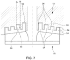
- FIG. 7 is a schematic representation showing projections of the impeller received in corresponding recesses of the housing of the pump assembly
- FIG. 8 is a schematic representation showing projections of the impeller including one of the projections comprising a wear ring;
- FIG. 9 is a schematic representation showing projections of the impeller received in corresponding recesses of the housing of the pump assembly including a recess formed in at least one projection and a corresponding recess of the housing;
- FIG. 10 is a schematic representation showing projections of the impeller received in corresponding recesses of the housing including a recess formed in at least one of the projections and a recess in a corresponding recess of the housing that is not directly aligned with the recess in the projection.
- FIGS. 1 to 3 components of a pump assembly 10 for use in an engine cooling circuit of a vehicle are shown.
- the pump assembly 10 is formed by a centrifugal pump 14 which circulates coolant in the form of water to components of an engine of the vehicle (not shown) for cooling.
- the pump assembly 10 comprises an impeller 16 and a pump housing 18 .
- the impeller 16 is disposed within the pump housing 18 and is rotatable relative to the housing 18 about a rotational axis. In use, the impeller 16 is driven to rotate, thereby pumping coolant received by the pump assembly 10 from a radiator of the vehicle (not shown) towards the engine of the vehicle to provide cooling.
- the pump housing 18 includes a front portion 20 and a rear portion 22 .
- the impeller 16 is housed in the front portion 20 of the housing 18 and is mounted at a first end 24 of a rotatable shaft 26 .
- the shaft 26 is rotatably supported in the housing 18 by a bearing arrangement 28 , and extends out of the housing 18 through an aperture 30 provided in the rear portion 22 of the housing 18 .
- a drive member 32 is attached at a second end 34 of the shaft 26 located outside of the pump housing 18 and is coupled to a crankshaft of the engine (not shown) via a pulley or belt assembly (not shown). In use, the crankshaft drives rotation of the drive member 32 and impeller 16 about a rotational axis of the shaft 26 via the pulley or belt system.
- the pump assembly 10 may be driven by an electric motor, for example when the assembly 10 is included in a hybrid vehicle.
- the front portion 20 of the housing 18 further includes an inlet or suction line 36 for receiving coolant to the pump assembly 10 and an outlet or discharge line, part of which is shown in FIG. 3 and indicated by numeral 37 , from which coolant exits the pump assembly 10 and is directed to coolant passages of the engine (not shown).
- the impeller 16 is best seen in FIGS. 1, 2 and 4 .
- the impeller 16 includes a front shroud or plate 40 , a back shroud or plate 42 and a plurality of blades 44 located therebetween.
- the front plate 40 slopes rearwardly away from the inlet 36 of the housing 18 and the back plate 42 is generally flat. It should be noted that in other embodiments the front and back plates, 40 , 42 , may be configured differently.
- a central aperture 46 is provided in the front plate 40 of the impeller 16 and this aperture 46 is aligned with the rotational axis of the shaft 26 and the inlet 36 of the pump housing 18 .
- the impeller 16 further includes circumferential apertures 48 about an outer edge 50 of the impeller 16 .
- the blades 44 of the impeller 16 are generally curved and extend from the central aperture 46 to the outer edge 50 of the impeller 16 .
- coolant enters the pump assembly 10 through the inlet 36 of the housing 18 and enters the rotating impeller 16 through the central aperture 46 of the front plate 40 .
- coolant As the impeller 16 rotates, coolant is forced radially outwards from the centre of the impeller 16 towards the circumferential outlet apertures 48 of the impeller 16 . From here, the coolant enters a volute 38 that surrounds the impeller 16 and is guided to the outlet 37 of the housing 18 and towards the engine for cooling. Thus, coolant is pumped from the inlet 36 of the pump assembly 10 to the outlet 37 of the pump assembly 10 .
- One issue that may arise in a pump assembly 10 relates to the unwanted flow of coolant along a route other than the intended flow path.
- coolant on exiting the impeller 16 , to flow back towards the inlet 36 of the housing via the space between the front plate 40 of the impeller 16 and the housing 18 in which the impeller 16 is encased.
- the effect of this is a reduction in efficiency of the pump assembly 10 .
- One way of reducing unwanted flow of coolant from the outlet 37 of the housing 18 back towards the inlet 36 of the housing 18 , and thus to improve efficiency of the system, is to provide the portion of the housing 18 that faces towards the front plate 40 of the impeller 16 with recesses to provide a labyrinth cover.
- this cover provides a seal, this design is not tolerant to radial misalignment. That is to say, misalignment between the longitudinal axis of the inlet and the rotational axis of the impeller affects the sealing properties in a design implementing such a labyrinth cover.
- the impeller 16 and pump assembly 10 of the invention provide improvement over this design, as will be explained. It is worthwhile noting here that whilst labyrinth seals have been implemented in steady state water pumps before, but have not before been utilised in automotive applications where different flow rates are required.
- the impeller 16 is provided with a plurality of projections or protrusions 54 , which are generally located between the inlet 36 and outlet 37 of the housing 18 when the pump assembly 10 is assembled.
- one or more of the projections 54 are received in one or more corresponding recesses 56 of the housing 18 to define a tortuous flow path 58 between the parts 54 , 56 , from the outlet to the inlet, which it is indirect and meandering, and is therefore difficult for coolant to flow along.
- This flow route or path 58 is best seen in FIG. 6 .
- a greater flow rate in the pump results in a more effective labyrinth. This is particularly important for the efficiency of engines requiring high cooling flows.
- three projections 54 are provided on the impeller 16 , although it is possible for more or fewer to be included. Providing a greater number of projections 54 on the impeller 16 may be beneficial in terms of providing a more circuitous flow route between the inlet 36 and outlet 37 of the housing 18 , thereby further restricting flow of coolant along this path.
- the projections 54 extend outwardly from an outer surface 60 of the front plate 40 of the impeller 16 in a direction parallel to the rotational axis of the impeller 16 and extend circumferentially about the rotational axis of the impeller 16 .
- the projections 54 are radially spaced on the outer surface 60 of the front plate 40 so as to form a pattern of concentric rings, as is best seen in FIG. 1 .
- the projections 54 are equally spaced from each other, but in other embodiments this may not be the case.
- a radially innermost projection is formed by a wearing ring or nose ring 100 as shown in FIG. 8 .
- each of the projections 54 is rectangular in cross-section in this embodiment of the invention.
- the radial width, w R , of each projection 54 is identical and has a value of 3.4 mm.
- the axial height, h A , of each of the projections 54 (defined as the absolute extent that each projection 54 protrudes away from the outer surface 60 of the front plate 40 of the impeller 16 ), is also identical in this embodiment and has a value of 4.5 mm. It should be noted that the present embodiment shows only one possible example of the size and shape of the projections 54 , but that many other sizes and shapes are possible within the inventive concept.
- the axial height, h A , and/or radial width, w R , of one or more of the projections 54 could be smaller or larger in other embodiments of the invention.
- the general shape of one or more of the projections 54 could be different in other embodiments.
- An example of another possible shape that the projections 54 could take is triangular, i.e. giving rise to a triangular cross-section. It should also be noted that it is not required for all of the projections 54 to have the same size and shape, but that it would be possible for one or more of the projections 54 to be shaped and/or sized differently to the other projections.
- FIGS. 8-10 show projections having different axial heights.
- the radially most inward projection 56 has a larger axial height compared to others of the projections 56 .
- FIG. 1 also shows a difference between the projections 56 .
- the radially most inward of the projections shown in FIG. 1 has a smaller radial width than the other projections shown there.
- Incorporating different shapes, sizes and configurations of the projections 54 may be beneficial to provide a more laborious and indirect route for the flow of coolant. It may be advantageous to provide the majority of the projections 54 with a shape which is relatively easy and inexpensive to manufacture and fewer projections 54 with a more complex shape which is more difficult to manufacture and/or more costly, but which provides additional deviation in the flow path. In this way, a balance may be struck between ease of manufacture, cost and efficiency of performance.
- projections 54 may aid in assembly of the impeller 16 to the housing 18 .
- one of the projections 54 of the impeller 16 defines a triangular cross section but the other projections 54 define rectangular cross sections, it may be helpful for the triangular projection to serve as a locating feature to locate the impeller 16 in the correct position with respect to the housing 18 .
- FIG. 3 shows a front section of the pump assembly 10 in which the front portion 20 of the housing 18 encasing the impeller 16 can be seen.
- the inlet 36 of the housing 18 is generally aligned with both the central aperture 46 of the impeller 16 and with the rotational axis of the impeller 16 , and transitions to a cover portion 62 that covers the front plate 40 of the impeller 16 .
- the cover portion 62 is dimensioned so as to substantially match the size and shape of the front plate 40 of the impeller 16 , but with a small clearance gap 64 provided therebetween to allow for rotation of the impeller 16 with respect to the housing 18 .
- the outlet 37 of the housing 18 is arranged at the circumference of the impeller 16 .
- This clearance space or gap 64 between the impeller and housing defines the tortuous and difficult flow route 58 for the coolant, as discussed earlier, thereby inhibiting or restricting flow of coolant from the outlet 37 of the housing 18 back towards the inlet 36 . That is to say, corresponding ones of the projections 54 and recesses 56 together inhibit coolant exiting the impeller 16 from flowing back towards the inlet 36 of the housing 18 in a direction which is against the intended direction of flow. In this way, the corresponding projections 54 and recesses 56 provide a labyrinth-type seal.
- the recesses 56 are formed in an inner surface 66 of the housing 18 and are dimensioned so as to receive the corresponding projections 54 with the clearance gap 64 therebetween.
- the housing 18 comprises three recesses 56 of identical size and shape, said recesses 56 being rectangular in cross-section and each receiving at least a portion of a corresponding projection 54 of the impeller 16 .
- coolant enters the pump assembly 10 from the inlet 36 of the housing 18 and passes through the central aperture 46 of the front plate 40 and into the impeller 16 .
- the impeller 16 rotates about the rotational axis of the shaft 26 on which it is mounted and coolant is expelled from the center of the impeller 16 towards the outer edge 50 of the impeller 16 .
- Coolant passes out of the impeller 16 through the circumferential apertures 48 and exits the pump assembly 10 from the outlet 37 of the housing 18 via the volute 38 . Coolant is then directed to the engine for cooling.
- the gap 64 is provided between the front plate 40 of the impeller 16 and the cover portion 62 of the housing 18 . Once coolant has exited the impeller 16 , it is possible for coolant to flow back towards the inlet 36 via this clearance gap 64 , rather than out of the outlet 37 of the housing 18 as intended. By virtue of the corresponding projections 54 and recesses 56 of the impeller 16 and housing 18 respectively, this unwanted back-flow towards the inlet 36 is reduced.
- projections 54 to engage with each of the recesses 56 provided in the housing 18 results in a greater tolerance to radial misalignment of the rotational axis of the impeller 16 (corresponding to the rotational axis of the shaft 26 ) and the longitudinal axis of the housing inlet 36 .
- this is because an increase in clearance gap between a first side 68 of a projection 54 and the inner surface 66 of the housing 18 , g 1 , is compensated by a decrease in clearance gap between a second opposing side 70 of the projection 54 and the inner surface 66 of the housing 18 , g 2 .
- the invention provides more stable efficiency of operation of the pump assembly 10 from low pump rates to high pump rates, resulting in a flatter operating curve.
- the invention results in improved conformity of production, such that variations in efficiency between different pump assemblies 10 produced according to the invention are reduced.
- This is compared to pump assembly designs using, for example, a labyrinth cover as discussed earlier, in which the peak efficiency may by slightly higher at moderate or average pump rates, but the efficiency falls off rapidly away from this pump rate towards higher or lower rates.
- the efficiency of these labyrinth cover systems falls off more rapidly in the event of misalignment of the impeller and housing (i.e. radial and angular misalignment of axes of the impeller and housing as described above) than in the system of the present invention.
- the invention is especially advantageous when utilized in larger, more powerful vehicles requiring a greater flow rate of coolant, in which the pump 10 may be operated at relatively higher pump rates as standard.
- a surface of at least one of the projections 54 of the impeller 16 , or a surface of the impeller 16 between adjacent projections 54 may be provided with at least one minor recess 110 , 120 .
- one or more secondary recesses 130 , 140 may be provided in a surface of at least one of the recesses 56 of the housing 18 , or in a surface of the housing 18 located between adjacent recesses 56 of the housing 18 .
- said recesses it is possible for said recesses to be aligned with one another as shown in FIG. 9 or to be offset from one another as shown in FIG. 10 .
Landscapes
- Engineering & Computer Science (AREA)
- General Engineering & Computer Science (AREA)
- Mechanical Engineering (AREA)
- Chemical & Material Sciences (AREA)
- Combustion & Propulsion (AREA)
- Physics & Mathematics (AREA)
- Thermal Sciences (AREA)
- Structures Of Non-Positive Displacement Pumps (AREA)
Abstract
Description
Claims (18)
Applications Claiming Priority (3)
| Application Number | Priority Date | Filing Date | Title |
|---|---|---|---|
| GB1719510.8 | 2017-11-24 | ||
| GB1719510 | 2017-11-24 | ||
| GB1719510.8A GB2568715B (en) | 2017-11-24 | 2017-11-24 | Pump assembly with tortuous flow path |
Publications (2)
| Publication Number | Publication Date |
|---|---|
| US20190162199A1 US20190162199A1 (en) | 2019-05-30 |
| US11092161B2 true US11092161B2 (en) | 2021-08-17 |
Family
ID=60950566
Family Applications (1)
| Application Number | Title | Priority Date | Filing Date |
|---|---|---|---|
| US16/185,345 Active 2039-03-17 US11092161B2 (en) | 2017-11-24 | 2018-11-09 | Impeller |
Country Status (3)
| Country | Link |
|---|---|
| US (1) | US11092161B2 (en) |
| DE (1) | DE102018218697A1 (en) |
| GB (1) | GB2568715B (en) |
Families Citing this family (3)
| Publication number | Priority date | Publication date | Assignee | Title |
|---|---|---|---|---|
| DE102019115774A1 (en) * | 2019-06-11 | 2020-12-17 | HELLA GmbH & Co. KGaA | Pump, in particular pump for a fluid circuit in a vehicle, with a rim of an impeller, immersed in a housing |
| DE102022210019A1 (en) * | 2022-09-22 | 2024-03-28 | Mahle International Gmbh | Oil module |
| US20240392720A1 (en) * | 2023-05-23 | 2024-11-28 | Ralf Centmayer | Engine coolant management |
Citations (16)
| Publication number | Priority date | Publication date | Assignee | Title |
|---|---|---|---|---|
| US2882075A (en) * | 1956-01-31 | 1959-04-14 | Thompson Prod Inc | Pump seal |
| US3055473A (en) | 1959-05-11 | 1962-09-25 | Eaton Mfg Co | Fluid coupling device |
| US4213735A (en) | 1979-02-01 | 1980-07-22 | Chandler Evans Inc. | Constant flow centrifugal pump |
| US4594052A (en) * | 1982-02-08 | 1986-06-10 | A. Ahlstrom Osakeyhtio | Centrifugal pump for liquids containing solid material |
| EP0417467A1 (en) | 1989-09-13 | 1991-03-20 | Eaton Corporation | Fluid coupling device and improved valving therefor |
| US6164655A (en) * | 1997-12-23 | 2000-12-26 | Asea Brown Boveri Ag | Method and arrangement for sealing off a separating gap, formed between a rotor and a stator, in a non-contacting manner |
| US6960066B2 (en) * | 2002-02-21 | 2005-11-01 | Aisin Seiki Kabushiki Kaisha | Water pump with a hollow shaft, seal, and drain opening therein |
| US20080260515A1 (en) | 2006-11-21 | 2008-10-23 | Matsushita Electric Works, Ltd. | Pump |
| US7445213B1 (en) * | 2006-06-14 | 2008-11-04 | Florida Turbine Technologies, Inc. | Stepped labyrinth seal |
| GB2508921A (en) | 2012-12-17 | 2014-06-18 | Valeo Air Man Uk Ltd | Compressing device with thermal protection provided by a labyrinth seal |
| US20140308142A1 (en) * | 2011-10-06 | 2014-10-16 | Xylem Ip Holdings Llc | Pump for pumping liquid comprising solid matter |
| WO2016051916A1 (en) | 2014-10-03 | 2016-04-07 | 三菱重工業株式会社 | Supercharger |
| WO2016059866A1 (en) | 2014-10-17 | 2016-04-21 | 三菱重工業株式会社 | Labyrinth seal, centrifugal compressor, and supercharger |
| US9650907B2 (en) * | 2011-09-12 | 2017-05-16 | Ansaldo Energia Ip Uk Limited | Labyrinth seal |
| EP3214287A1 (en) | 2014-10-28 | 2017-09-06 | Mitsubishi Heavy Industries, Ltd. | Supercharger and engine with same |
| US9765792B2 (en) | 2011-11-10 | 2017-09-19 | Continental Automotive Gmbh | Centrifugal pump for delivering liquids in a motor vehicle |
-
2017
- 2017-11-24 GB GB1719510.8A patent/GB2568715B/en active Active
-
2018
- 2018-10-31 DE DE102018218697.9A patent/DE102018218697A1/en not_active Withdrawn
- 2018-11-09 US US16/185,345 patent/US11092161B2/en active Active
Patent Citations (17)
| Publication number | Priority date | Publication date | Assignee | Title |
|---|---|---|---|---|
| US2882075A (en) * | 1956-01-31 | 1959-04-14 | Thompson Prod Inc | Pump seal |
| US3055473A (en) | 1959-05-11 | 1962-09-25 | Eaton Mfg Co | Fluid coupling device |
| US4213735A (en) | 1979-02-01 | 1980-07-22 | Chandler Evans Inc. | Constant flow centrifugal pump |
| US4594052A (en) * | 1982-02-08 | 1986-06-10 | A. Ahlstrom Osakeyhtio | Centrifugal pump for liquids containing solid material |
| EP0417467A1 (en) | 1989-09-13 | 1991-03-20 | Eaton Corporation | Fluid coupling device and improved valving therefor |
| US6164655A (en) * | 1997-12-23 | 2000-12-26 | Asea Brown Boveri Ag | Method and arrangement for sealing off a separating gap, formed between a rotor and a stator, in a non-contacting manner |
| US6960066B2 (en) * | 2002-02-21 | 2005-11-01 | Aisin Seiki Kabushiki Kaisha | Water pump with a hollow shaft, seal, and drain opening therein |
| US7445213B1 (en) * | 2006-06-14 | 2008-11-04 | Florida Turbine Technologies, Inc. | Stepped labyrinth seal |
| US20080260515A1 (en) | 2006-11-21 | 2008-10-23 | Matsushita Electric Works, Ltd. | Pump |
| US9650907B2 (en) * | 2011-09-12 | 2017-05-16 | Ansaldo Energia Ip Uk Limited | Labyrinth seal |
| US20140308142A1 (en) * | 2011-10-06 | 2014-10-16 | Xylem Ip Holdings Llc | Pump for pumping liquid comprising solid matter |
| US9765792B2 (en) | 2011-11-10 | 2017-09-19 | Continental Automotive Gmbh | Centrifugal pump for delivering liquids in a motor vehicle |
| GB2508921A (en) | 2012-12-17 | 2014-06-18 | Valeo Air Man Uk Ltd | Compressing device with thermal protection provided by a labyrinth seal |
| US20150345373A1 (en) | 2012-12-17 | 2015-12-03 | Valeo Air Management Uk Limited | Compressing device with thermal protection |
| WO2016051916A1 (en) | 2014-10-03 | 2016-04-07 | 三菱重工業株式会社 | Supercharger |
| WO2016059866A1 (en) | 2014-10-17 | 2016-04-21 | 三菱重工業株式会社 | Labyrinth seal, centrifugal compressor, and supercharger |
| EP3214287A1 (en) | 2014-10-28 | 2017-09-06 | Mitsubishi Heavy Industries, Ltd. | Supercharger and engine with same |
Non-Patent Citations (2)
| Title |
|---|
| Combined Search and Examination Report under Sections 17 and 18(3) for Application No. GB1719510.8 dated May 24, 2018. |
| Search Report for German Application No. 10 2018 218 697.9 dated Jul. 13, 2020. |
Also Published As
| Publication number | Publication date |
|---|---|
| GB2568715B (en) | 2020-02-26 |
| DE102018218697A1 (en) | 2019-05-29 |
| US20190162199A1 (en) | 2019-05-30 |
| GB201719510D0 (en) | 2018-01-10 |
| GB2568715A (en) | 2019-05-29 |
Similar Documents
| Publication | Publication Date | Title |
|---|---|---|
| US8403630B2 (en) | Blade shroud with fluid barrier jet generation | |
| CA2496543C (en) | Recirculation structure for a turbocompressor | |
| US11092161B2 (en) | Impeller | |
| US20160025095A1 (en) | Electric pump | |
| US9551354B2 (en) | Regenerative-type fluid machinery having a guide vane on a channel wall | |
| CA2691186C (en) | Stator vane for a gas turbine engine | |
| US9121298B2 (en) | Finned seal assembly for gas turbine engines | |
| US8740575B2 (en) | Liquid ring pump with liner | |
| CN105715669A (en) | Dual thrust bearing for a turbocharger | |
| US20160245304A1 (en) | Compressor housing for supercharger | |
| EP2535596B1 (en) | Centrifugal compressor using an asymmetric self-recirculating casing treatment | |
| EP3078861B1 (en) | Multi-stage electrically-powered centrifugal compressor | |
| US6638009B2 (en) | Impeller of liquid pump | |
| JP7299757B2 (en) | impeller and centrifugal pump | |
| JP2016031064A (en) | Multiple stage pump | |
| US6499941B1 (en) | Pressure equalization in fuel pump | |
| KR20220119829A (en) | Impeller for water pump | |
| US8506238B2 (en) | Water pump with housing/impeller to enhance seal performance | |
| US20140030086A1 (en) | Centrifugal pump | |
| US20100021282A1 (en) | Side-Channel Pump | |
| US11105336B2 (en) | Impeller and centrifugal compressor | |
| EP4483062B1 (en) | A multi-stage centrifugal pump comprising an assembly for compensating axial forces | |
| KR20100025543A (en) | Fuel pump | |
| US5749707A (en) | Water pumps | |
| US20160376900A1 (en) | Stator device for a continuous-flow machine with a housing appliance and multiple guide vanes |
Legal Events
| Date | Code | Title | Description |
|---|---|---|---|
| AS | Assignment |
Owner name: JAGUAR LAND ROVER LIMITED, UNITED KINGDOM Free format text: ASSIGNMENT OF ASSIGNORS INTEREST;ASSIGNOR:ALBRECHT, MATTHEW;REEL/FRAME:047462/0275 Effective date: 20181104 |
|
| FEPP | Fee payment procedure |
Free format text: ENTITY STATUS SET TO UNDISCOUNTED (ORIGINAL EVENT CODE: BIG.); ENTITY STATUS OF PATENT OWNER: LARGE ENTITY |
|
| STPP | Information on status: patent application and granting procedure in general |
Free format text: DOCKETED NEW CASE - READY FOR EXAMINATION |
|
| STPP | Information on status: patent application and granting procedure in general |
Free format text: NON FINAL ACTION MAILED |
|
| STPP | Information on status: patent application and granting procedure in general |
Free format text: RESPONSE TO NON-FINAL OFFICE ACTION ENTERED AND FORWARDED TO EXAMINER |
|
| STPP | Information on status: patent application and granting procedure in general |
Free format text: NOTICE OF ALLOWANCE MAILED -- APPLICATION RECEIVED IN OFFICE OF PUBLICATIONS |
|
| STPP | Information on status: patent application and granting procedure in general |
Free format text: PUBLICATIONS -- ISSUE FEE PAYMENT RECEIVED |
|
| STPP | Information on status: patent application and granting procedure in general |
Free format text: PUBLICATIONS -- ISSUE FEE PAYMENT VERIFIED |
|
| STCF | Information on status: patent grant |
Free format text: PATENTED CASE |
|
| MAFP | Maintenance fee payment |
Free format text: PAYMENT OF MAINTENANCE FEE, 4TH YEAR, LARGE ENTITY (ORIGINAL EVENT CODE: M1551); ENTITY STATUS OF PATENT OWNER: LARGE ENTITY Year of fee payment: 4 |