US11090944B2 - Liquid storage bottle - Google Patents
Liquid storage bottle Download PDFInfo
- Publication number
- US11090944B2 US11090944B2 US16/822,837 US202016822837A US11090944B2 US 11090944 B2 US11090944 B2 US 11090944B2 US 202016822837 A US202016822837 A US 202016822837A US 11090944 B2 US11090944 B2 US 11090944B2
- Authority
- US
- United States
- Prior art keywords
- rib
- cap
- nozzle
- peripheral surface
- axial direction
- Prior art date
- Legal status (The legal status is an assumption and is not a legal conclusion. Google has not performed a legal analysis and makes no representation as to the accuracy of the status listed.)
- Active
Links
Images


Classifications
-
- B—PERFORMING OPERATIONS; TRANSPORTING
- B65—CONVEYING; PACKING; STORING; HANDLING THIN OR FILAMENTARY MATERIAL
- B65D—CONTAINERS FOR STORAGE OR TRANSPORT OF ARTICLES OR MATERIALS, e.g. BAGS, BARRELS, BOTTLES, BOXES, CANS, CARTONS, CRATES, DRUMS, JARS, TANKS, HOPPERS, FORWARDING CONTAINERS; ACCESSORIES, CLOSURES, OR FITTINGS THEREFOR; PACKAGING ELEMENTS; PACKAGES
- B65D23/00—Details of bottles or jars not otherwise provided for
-
- B—PERFORMING OPERATIONS; TRANSPORTING
- B65—CONVEYING; PACKING; STORING; HANDLING THIN OR FILAMENTARY MATERIAL
- B65D—CONTAINERS FOR STORAGE OR TRANSPORT OF ARTICLES OR MATERIALS, e.g. BAGS, BARRELS, BOTTLES, BOXES, CANS, CARTONS, CRATES, DRUMS, JARS, TANKS, HOPPERS, FORWARDING CONTAINERS; ACCESSORIES, CLOSURES, OR FITTINGS THEREFOR; PACKAGING ELEMENTS; PACKAGES
- B65D41/00—Caps, e.g. crown caps or crown seals, i.e. members having parts arranged for engagement with the external periphery of a neck or wall defining a pouring opening or discharge aperture; Protective cap-like covers for closure members, e.g. decorative covers of metal foil or paper
- B65D41/02—Caps or cap-like covers without lines of weakness, tearing strips, tags, or like opening or removal devices
- B65D41/04—Threaded or like caps or cap-like covers secured by rotation
- B65D41/0407—Threaded or like caps or cap-like covers secured by rotation with integral sealing means
- B65D41/0414—Threaded or like caps or cap-like covers secured by rotation with integral sealing means formed by a plug, collar, flange, rib or the like contacting the internal surface of a container neck
- B65D41/0421—Threaded or like caps or cap-like covers secured by rotation with integral sealing means formed by a plug, collar, flange, rib or the like contacting the internal surface of a container neck and combined with integral sealing means contacting other surfaces of a container neck
-
- B—PERFORMING OPERATIONS; TRANSPORTING
- B41—PRINTING; LINING MACHINES; TYPEWRITERS; STAMPS
- B41J—TYPEWRITERS; SELECTIVE PRINTING MECHANISMS, i.e. MECHANISMS PRINTING OTHERWISE THAN FROM A FORME; CORRECTION OF TYPOGRAPHICAL ERRORS
- B41J2/00—Typewriters or selective printing mechanisms characterised by the printing or marking process for which they are designed
- B41J2/005—Typewriters or selective printing mechanisms characterised by the printing or marking process for which they are designed characterised by bringing liquid or particles selectively into contact with a printing material
- B41J2/01—Ink jet
- B41J2/135—Nozzles
-
- B—PERFORMING OPERATIONS; TRANSPORTING
- B41—PRINTING; LINING MACHINES; TYPEWRITERS; STAMPS
- B41J—TYPEWRITERS; SELECTIVE PRINTING MECHANISMS, i.e. MECHANISMS PRINTING OTHERWISE THAN FROM A FORME; CORRECTION OF TYPOGRAPHICAL ERRORS
- B41J2/00—Typewriters or selective printing mechanisms characterised by the printing or marking process for which they are designed
- B41J2/005—Typewriters or selective printing mechanisms characterised by the printing or marking process for which they are designed characterised by bringing liquid or particles selectively into contact with a printing material
- B41J2/01—Ink jet
- B41J2/17—Ink jet characterised by ink handling
- B41J2/175—Ink supply systems ; Circuit parts therefor
- B41J2/17503—Ink cartridges
- B41J2/17506—Refilling of the cartridge
- B41J2/17509—Whilst mounted in the printer
-
- B—PERFORMING OPERATIONS; TRANSPORTING
- B41—PRINTING; LINING MACHINES; TYPEWRITERS; STAMPS
- B41J—TYPEWRITERS; SELECTIVE PRINTING MECHANISMS, i.e. MECHANISMS PRINTING OTHERWISE THAN FROM A FORME; CORRECTION OF TYPOGRAPHICAL ERRORS
- B41J2/00—Typewriters or selective printing mechanisms characterised by the printing or marking process for which they are designed
- B41J2/005—Typewriters or selective printing mechanisms characterised by the printing or marking process for which they are designed characterised by bringing liquid or particles selectively into contact with a printing material
- B41J2/01—Ink jet
- B41J2/17—Ink jet characterised by ink handling
- B41J2/175—Ink supply systems ; Circuit parts therefor
- B41J2/17503—Ink cartridges
- B41J2/1752—Mounting within the printer
- B41J2/17523—Ink connection
-
- B—PERFORMING OPERATIONS; TRANSPORTING
- B41—PRINTING; LINING MACHINES; TYPEWRITERS; STAMPS
- B41J—TYPEWRITERS; SELECTIVE PRINTING MECHANISMS, i.e. MECHANISMS PRINTING OTHERWISE THAN FROM A FORME; CORRECTION OF TYPOGRAPHICAL ERRORS
- B41J2/00—Typewriters or selective printing mechanisms characterised by the printing or marking process for which they are designed
- B41J2/005—Typewriters or selective printing mechanisms characterised by the printing or marking process for which they are designed characterised by bringing liquid or particles selectively into contact with a printing material
- B41J2/01—Ink jet
- B41J2/17—Ink jet characterised by ink handling
- B41J2/175—Ink supply systems ; Circuit parts therefor
- B41J2/17503—Ink cartridges
- B41J2/17536—Protection of cartridges or parts thereof, e.g. tape
- B41J2/1754—Protection of cartridges or parts thereof, e.g. tape with means attached to the cartridge, e.g. protective cap
-
- B—PERFORMING OPERATIONS; TRANSPORTING
- B41—PRINTING; LINING MACHINES; TYPEWRITERS; STAMPS
- B41J—TYPEWRITERS; SELECTIVE PRINTING MECHANISMS, i.e. MECHANISMS PRINTING OTHERWISE THAN FROM A FORME; CORRECTION OF TYPOGRAPHICAL ERRORS
- B41J2/00—Typewriters or selective printing mechanisms characterised by the printing or marking process for which they are designed
- B41J2/005—Typewriters or selective printing mechanisms characterised by the printing or marking process for which they are designed characterised by bringing liquid or particles selectively into contact with a printing material
- B41J2/01—Ink jet
- B41J2/17—Ink jet characterised by ink handling
- B41J2/175—Ink supply systems ; Circuit parts therefor
- B41J2/17503—Ink cartridges
- B41J2/17553—Outer structure
-
- B—PERFORMING OPERATIONS; TRANSPORTING
- B41—PRINTING; LINING MACHINES; TYPEWRITERS; STAMPS
- B41J—TYPEWRITERS; SELECTIVE PRINTING MECHANISMS, i.e. MECHANISMS PRINTING OTHERWISE THAN FROM A FORME; CORRECTION OF TYPOGRAPHICAL ERRORS
- B41J29/00—Details of, or accessories for, typewriters or selective printing mechanisms not otherwise provided for
- B41J29/02—Framework
-
- B—PERFORMING OPERATIONS; TRANSPORTING
- B41—PRINTING; LINING MACHINES; TYPEWRITERS; STAMPS
- B41J—TYPEWRITERS; SELECTIVE PRINTING MECHANISMS, i.e. MECHANISMS PRINTING OTHERWISE THAN FROM A FORME; CORRECTION OF TYPOGRAPHICAL ERRORS
- B41J29/00—Details of, or accessories for, typewriters or selective printing mechanisms not otherwise provided for
- B41J29/12—Guards, shields or dust excluders
- B41J29/13—Cases or covers
-
- B—PERFORMING OPERATIONS; TRANSPORTING
- B65—CONVEYING; PACKING; STORING; HANDLING THIN OR FILAMENTARY MATERIAL
- B65D—CONTAINERS FOR STORAGE OR TRANSPORT OF ARTICLES OR MATERIALS, e.g. BAGS, BARRELS, BOTTLES, BOXES, CANS, CARTONS, CRATES, DRUMS, JARS, TANKS, HOPPERS, FORWARDING CONTAINERS; ACCESSORIES, CLOSURES, OR FITTINGS THEREFOR; PACKAGING ELEMENTS; PACKAGES
- B65D41/00—Caps, e.g. crown caps or crown seals, i.e. members having parts arranged for engagement with the external periphery of a neck or wall defining a pouring opening or discharge aperture; Protective cap-like covers for closure members, e.g. decorative covers of metal foil or paper
- B65D41/32—Caps or cap-like covers with lines of weakness, tearing-strips, tags, or like opening or removal devices, e.g. to facilitate formation of pouring openings
- B65D41/34—Threaded or like caps or cap-like covers provided with tamper elements formed in, or attached to, the closure skirt
Definitions
- the present disclosure relates to a liquid storage bottle which stores a liquid therein.
- a liquid can be replenished from a separately prepared liquid storage bottle through an inlet for injecting the liquid.
- the liquid storage bottle for replenishing the liquid in order to prevent hands or surroundings of a user from being dirty, one of an inner peripheral surface and an outer peripheral surface of a tip of a nozzle for discharging the liquid is sealed. Accordingly, the liquid storage bottle can have seal property so that the liquid does not leak. This is particularly important because when a content is ink, a general surface tension (about 30 mN/m) of the ink is smaller than a surface tension (about 73 mN/m) of water, and thus, the ink easily leaks even from a small gap.
- Japanese Patent Application Laid-Open No. 2004-352360 discloses a sealing structure of a bottle capable of sealing both an inner peripheral surface and an outer peripheral surface of a nozzle tip.
- An aspect of the present disclosure is to provide a liquid storage bottle which suppresses liquid leakage due to an external impact while reducing the operation force required when opening or closing the cap.
- a liquid storage bottle including: a bottle main body; a nozzle which has a discharge port through which a liquid stored in the bottle main body is discharged; a cylindrical cap which is mountable on the nozzle to open or close the discharge port; and a sealing unit which seals the discharge port when the cap is mounted on the nozzle, in which the sealing unit includes an annular first rib which is provided in the nozzle, an annular second rib which is provided in the cap and an annular or arc third rib which is provided in the cap, the first rib protrudes in an axial direction of the nozzle along a peripheral edge portion of the discharge port, the second rib protrudes in an axial direction of the cap from a surface of the cap facing the discharge port and includes an outer peripheral surface which is fitted to an inner peripheral surface of the first rib, the third rib protrudes in the axial direction of the cap from the surface of the cap facing the discharge port and includes an inner peripheral surface which comes into contact with an outer peripheral surface of the sealing unit
- FIG. 1 is a perspective view of an example liquid ejection device used in a liquid storage bottle of the present disclosure.
- FIG. 2 is a perspective view illustrating an example internal configuration of a main part of the liquid ejection device illustrated in FIG. 1 .
- FIG. 3 is a perspective view of an example liquid tank of the liquid ejection device illustrated in FIG. 1 .
- FIG. 4 is a side view of a liquid storage bottle according to a first example embodiment.
- FIG. 5 is an exploded side view of the liquid storage bottle illustrated in FIG. 4 .
- FIG. 6 is a cross-sectional view of a nozzle and a cap according to the first example embodiment.
- FIG. 7 is a cross-sectional view of the cap when the cap is mounted on the nozzle.
- FIG. 8A is an enlarged cross-sectional view of a sealing state of a sealing unit according to the first example embodiment.
- FIG. 8B is an enlarged cross-sectional view in a state where sealing of the sealing unit according to the first example embodiment is released.
- FIGS. 9A, 9B, 9C and 9D are enlarged cross-sectional views illustrating modification examples of the sealing unit according to the first example embodiment.
- FIG. 10 is an enlarged cross-sectional view illustrating a modification example of the sealing unit according to the first example embodiment.
- FIG. 11 is a bottom view of a cap according to a second example embodiment.
- FIG. 12 is an enlarged cross-sectional view of a sealing unit according to the second example embodiment.
- FIG. 13 is an enlarged cross-sectional view of a sealing unit according to a third example embodiment.
- FIG. 1 is a perspective view of a liquid ejection device used in a liquid storage bottle of the present disclosure.
- a liquid ejection device 1 is a serial type ink jet recording device and has a housing 11 and large-capacity liquid tanks 12 which are disposed inside the housing 11 .
- the liquid tank 12 stores ink which is a liquid ejected to a recording medium (not illustrated).
- FIG. 2 is a perspective view illustrating an internal configuration of a main part of the liquid ejection device 1 illustrated in FIG. 1 .
- the liquid ejection device 1 includes a conveyance roller 13 which conveys the recording medium (not illustrated), a carriage 15 in which a recording head 14 for ejecting a liquid is provided and a carriage motor 16 which drives the carriage 15 .
- the recording medium is paper.
- the recording medium is not particularly limited as long as an image is formed by the liquid ejected from the recording head 14 .
- the conveyance roller 13 is intermittently driven rotationally, and thus, the recording medium is intermittently conveyed.
- the carriage motor 16 is rotationally driven, the carriage 15 reciprocates in a direction intersecting a conveyance direction of the recording medium and the liquid is ejected to the recording medium from an ejection port provided in the recording head 14 during reciprocating scanning of the carriage 15 . Accordingly, the image is recorded on the recording medium.
- the liquid is stored in the liquid tank 12 and is supplied to the recording head 14 through a liquid flow path 17 .
- ink of four colors for example, cyan, magenta, yellow and black
- the liquid tank 12 four liquid tanks 12 a to 12 d each storing the ink of each color are provided.
- Each of the four liquid tanks 12 a to 12 d is disposed in a front surface portion of the liquid ejection device 1 inside the housing 11 .
- FIG. 3 is a perspective view of the liquid tank 12 of the liquid ejection device 1 illustrated in FIG. 1 .
- An inside of the liquid tank 12 is partitioned into a storage chamber 121 for storing the liquid and a buffer chamber 122 for storing air, and a portion of a bottom wall of the storage chamber 121 forms a ceiling wall of the buffer chamber 122 .
- the storage chamber 121 and the buffer chamber 122 communicate with each other via a communication flow path 123 which is provided along one of side walls of the storage chamber 121 .
- An opening portion 124 which is an outlet of the buffer chamber 122 side of the communication flow path 123 is provided on a lower side of the buffer chamber 122 .
- a supply port 125 which communicates with the recording head 14 via a tube (not illustrated) and through which the liquid is supplied to the recording head 14 is provided at an end portion of a bottom wall of the storage chamber 121 .
- An inlet 126 for replenishing the liquid tank 12 with the liquid is provided on an upper surface of the liquid tank 12 .
- a tank cap 127 for sealing the storage chamber 121 in the liquid tank 12 can be mounted on the inlet 126 .
- FIG. 3 illustrates the liquid tank 12 on which the tank cap 127 mounted.
- An air opening 128 is provided on the upper surface of the liquid tank 12 to allow the buffer chamber 122 to communicate with the outside air.
- FIG. 4 is a side view of a liquid storage bottle 2 according to a first embodiment of the present disclosure.
- FIG. 5 is an exploded side view of the liquid storage bottle 2 illustrated in FIG. 4 .
- the liquid storage bottle 2 is a cylindrical container for replenishing the liquid tank 12 with the liquid, and includes a bottle main body 21 which stores the liquid, a nozzle 22 and a cap 23 .
- the nozzle 22 is fixed to the bottle main body 21 and has a function of discharging the liquid stored in the bottle main body 21 .
- the cap 23 can be mounted on the nozzle 22 so as to open and close a discharge port 22 c described later of the nozzle 22 , and has a function of shielding an inside of the bottle main body 21 from an outside air and sealing the liquid storage bottle 2 .
- both the bottle main body 21 and the nozzle 22 are resin parts and are fixed to each other by welding as described later. However, the bottle main body 21 and the nozzle 22 may be sealed with a flexible part therebetween so as to be fixed to each other.
- a bottle welding portion 21 a is formed in an upper portion of the bottle main body 21 and a nozzle welding portion 22 a is formed in a lower portion of the nozzle 22 .
- One of an inner peripheral surface and a bottom surface of the nozzle welding portion 22 a is welded to the bottle welding portion 21 a , and thus, the nozzle 22 is fixed to the bottle main body 21 .
- a nozzle screw portion 22 b having a male screw formed on an outer peripheral surface is formed at a center portion of the nozzle 22 and a cap screw portion 23 a having a female screw formed on an inner peripheral surface is formed in a lower portion of the cap 23 .
- the male screw of the nozzle screw portion 22 b is screwed to the female screw of the cap screw portion 23 a , and thus, the cap 23 is mounted on the nozzle 22 .
- FIG. 6 is a cross-sectional view of the nozzle 22 and the cap 23 of the liquid storage bottle 2 of the first embodiment
- FIG. 7 is a cross-sectional view of the nozzle 22 and the cap 23 when the cap 23 is mounted on the nozzle 22 .
- An axial direction X in FIG. 7 is a direction substantially parallel to a longitudinal direction of the liquid storage bottle 2 and vertically intersects with a plane formed by the axial directions Y and Z.
- the plane formed by the axial directions Y and Z is substantially parallel to a plane formed by the liquid in the liquid storage bottle 2 when the liquid is stored in the liquid storage bottle 2 and the cap 23 is established upward.
- a relationship between the axial directions X, Y and Z is the same.
- a direction parallel to the axial direction X is defined as a longitudinal direction.
- the nozzle 22 has the discharge port 22 c which discharges the liquid.
- a sealing unit 30 which seals the discharge port 22 c when the cap 23 is mounted on the nozzle 22 is provided between the nozzle 22 and the cap 23 .
- the sealing unit 30 includes an annular first rib 31 which is provided on the nozzle 22 and both annular second and third ribs 32 and 33 which are provided on the cap 23 .
- the first rib 31 protrudes in the axial direction X of the nozzle 22 along a peripheral edge portion of the discharge port 22 c and the second and third ribs 32 and 33 respectively protrude in the axial direction X of the cap 23 from a bottom surface (a surface facing the discharge port 22 c ) of the cap 23 .
- the cap 23 includes an abutment surface 24 which abuts on the nozzle 22 in the axial direction X of the cap 23 when the cap 23 is mounted on the nozzle 22 . Accordingly, excessive tightening of the cap is suppressed and sealing of the discharge port 22 c by the sealing unit 30 is appropriately performed.
- FIG. 8A is an enlarged cross-sectional view of the sealing unit of the first embodiment and FIG. 8B is an enlarged cross-sectional view of the sealing unit when the sealing of the discharge port 22 c is released.
- the second rib 32 has an outer peripheral surface 32 a which is fitted to the inner peripheral surface 31 a of the first rib 31 when the cap 23 is mounted on the nozzle 22 .
- a diameter ⁇ 2 of the outer peripheral surface 32 a of the second rib 32 is larger than the diameter ⁇ 1 of the inner peripheral surface 31 a of the first rib 31 . Therefore, when the cap 23 is mounted on the nozzle 22 , the outer peripheral surface 32 a of the second rib 32 can be press-fitted into the inner peripheral surface 31 a of the first rib 31 . Accordingly, the inner peripheral surface 31 a of the first rib 31 can be sealed by the second rib 32 , and thus, the discharge port 22 c of the nozzle 22 can be sealed.
- the third rib 33 has an inner peripheral surface 33 a which comes into contact with the outer peripheral surface 31 b of the first rib 31 when the outer peripheral surface 32 a of the second rib 32 is fitted to the inner peripheral surface 31 a of the first rib 31 . Accordingly, in a case where the first rib 31 is deformed radially outward by the press-fitting of the second rib 32 , the third rib 33 can apply a radially inward reaction force to the outer peripheral surface 31 b of the first rib 31 . As a result, seal property between the inner peripheral surface 31 a of the first rib 31 and the outer peripheral surface 32 a of the second rib 32 can be further improved.
- the third rib 33 can apply the radially inward reaction force to the outer peripheral surface 31 b of the first rib 31 .
- the inner peripheral surface 33 a of the third rib 33 is inclined with respect to the axial direction X of the cap 23 so that a diameter increases toward a tip portion of the third rib 33 .
- a vertical force acting when the cap 23 is mounted is dispersed on an inclined surface, and thus, an operation force required when opening and closing the cap 23 can be reduced.
- the outer peripheral surface 31 b of the first rib 31 is inclined with respect to the axial direction X of the nozzle 22 so that a diameter decreases toward a tip portion of the first rib 31 .
- the vertical force acting when the cap 23 is mounted is dispersed on the inclined surface and a contact surface pressure between the first rib 31 and the third rib 33 is reduced. Accordingly, it is possible to suppress an increase in the operation force required when opening or closing the cap 23 .
- An inclination angle ⁇ 1 of the outer peripheral surface 31 b of the first rib 31 with respect to the axial direction X of the nozzle 22 and an inclination angle ⁇ 2 of the inner peripheral surface 33 a of the third rib 33 with respect to the axial direction X of the cap 23 can satisfy relationships of 0° ⁇ 1 ⁇ 45° and 0° ⁇ 2 ⁇ 45° or can satisfy relationships of 0° ⁇ 1 ⁇ 45° and 0° ⁇ 2 ⁇ 45°.
- a component F 1 sin ⁇ 1 in a direction opposite to a mounting direction (direction opposite to the axial direction X) of the cap 23 can be reduced.
- the operation force required when opening and closing the cap 23 can be reduced.
- a reaction force F 2 of the third rib 33 acting on the first rib 31 a radially inward component F 2 cos ⁇ 2 can be increased.
- a radially outward deformation of the first rib 31 can be suppressed and a sealing state of the discharge port 22 c can be maintained even when the liquid storage bottle 2 is dropped.
- FIGS. 9A to 9D are enlarged cross-sectional views illustrating modification examples of the second rib in the sealing unit of the first embodiment.
- FIG. 10 is an enlarged cross-sectional view illustrating modification examples of the first rib and the second rib of the sealing unit of the first embodiment.
- not only the outer peripheral surface 31 b of the first rib 31 and the inner peripheral surface 33 a of the third rib 33 can be inclined, but also the inner peripheral surface 31 a of the first rib 31 and outer peripheral surface 32 a of the second rib 32 can be inclined.
- the inner peripheral surface 31 a of the first rib 31 can be inclined with respect to the axial direction X of the nozzle 22 so that a diameter increases toward the tip portion of the first rib 31 .
- the outer peripheral surface 32 a of the second rib 32 can be inclined with respect to the axial direction X of the cap 23 so that a diameter decreases toward the tip portion of the second rib 32 . Accordingly, a contact surface pressure between the first rib 31 and the second rib 32 decreases, and thus, it is possible to further suppress the increase in the operation force required when opening or closing the cap 23 .
- FIG. 11 is a bottom view of a cap 23 of a liquid storage bottle according to a second embodiment of the present disclosure.
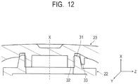
- FIG. 12 is an enlarged cross-sectional view of a sealing unit of the liquid storage bottle according to the second embodiment.
- the same components as those of the first embodiment are denoted by the same reference numerals in the drawings, description thereof will be omitted, and only configurations different from those of the first embodiment will be described.
- the sealed space is formed between the tip portion of the first rib 31 and the cap 23 is formed. Accordingly, in the case where a pressure difference between the inside and the outside of the liquid storage bottle 2 occurs, the liquid inside the liquid storage bottle 2 may be discharged when the cap 23 is opened. Meanwhile, in the second embodiment, the third rib 33 is formed in an arc shape. Accordingly, when the cap 23 is closed, the space formed between the tip portion of the first rib 31 and the cap 23 is not sealed and communicates with the outside air.
- the number of third ribs 33 is not particularly limited as long as the third ribs 33 are formed in an arc shape instead of an annular shape. That is, the number of third ribs 33 may be one or two or may be four or more, in addition to the illustrated three.
- FIG. 13 is an enlarged cross-sectional view of a sealing unit according to a third embodiment of the present disclosure.
- the same components as those of the above-described embodiments are denoted by the same reference numerals in the drawings, description thereof will be omitted and only configurations different from those of the above-described embodiments will be described.
- the tip portion 33 b of the third rib 33 abuts on the nozzle 22 in the axial direction X of the cap 23 when the cap 23 is mounted on the nozzle 22 . Accordingly, a radially inward frictional force is generated at the tip portion 33 b of the third rib 33 , and thus, it is possible to prevent the third rib 33 from being deformed radially outward when an impact is applied from the outside such as dropping. Moreover, in this case, the tip portion 33 b of the third rib 33 is radially separated from the outer peripheral surface 31 b of the first rib 31 .
- the tip portion 33 b of the third rib 33 does not interfere with the outer peripheral surface 31 b of the first rib 31 when the cap 23 is opened and closed. Therefore, even when the tip portion 33 b of the third rib 33 abuts on the nozzle 22 when the cap 23 is mounted on the nozzle 22 , the operation force required when opening and closing the cap 23 does not increase. Moreover, the tip portion 33 b of the third rib 33 may abut on the nozzle 22 before the abutment surface 24 of the cap 23 abuts on the nozzle 22 so as to suppress excessive tightening of the cap 23 .
Landscapes
- Engineering & Computer Science (AREA)
- Mechanical Engineering (AREA)
- Closures For Containers (AREA)
- Ink Jet (AREA)
Abstract
Description
Claims (8)
Applications Claiming Priority (3)
| Application Number | Priority Date | Filing Date | Title |
|---|---|---|---|
| JPJP2019-060581 | 2019-03-27 | ||
| JP2019060581A JP7336227B2 (en) | 2019-03-27 | 2019-03-27 | ink bottle |
| JP2019-060581 | 2019-03-27 |
Publications (2)
| Publication Number | Publication Date |
|---|---|
| US20200307228A1 US20200307228A1 (en) | 2020-10-01 |
| US11090944B2 true US11090944B2 (en) | 2021-08-17 |
Family
ID=72606926
Family Applications (1)
| Application Number | Title | Priority Date | Filing Date |
|---|---|---|---|
| US16/822,837 Active US11090944B2 (en) | 2019-03-27 | 2020-03-18 | Liquid storage bottle |
Country Status (3)
| Country | Link |
|---|---|
| US (1) | US11090944B2 (en) |
| JP (1) | JP7336227B2 (en) |
| CN (1) | CN111746903B (en) |
Families Citing this family (1)
| Publication number | Priority date | Publication date | Assignee | Title |
|---|---|---|---|---|
| JP2024167964A (en) * | 2023-05-23 | 2024-12-05 | キヤノン株式会社 | Liquid storage container and liquid refill system |
Citations (2)
| Publication number | Priority date | Publication date | Assignee | Title |
|---|---|---|---|---|
| JP2004352360A (en) | 2003-05-08 | 2004-12-16 | Toyo Seikan Kaisha Ltd | Nozzle structure of bottle |
| US10239323B2 (en) * | 2016-05-31 | 2019-03-26 | Seiko Epson Corporation | Bottle set |
Family Cites Families (7)
| Publication number | Priority date | Publication date | Assignee | Title |
|---|---|---|---|---|
| US5549213A (en) * | 1991-11-12 | 1996-08-27 | Edward S. Robbins, III | Reusable re-collapsible container and resealable cap |
| US20080110851A1 (en) * | 2006-10-13 | 2008-05-15 | Owens-Illinois Closure Inc. | Dual seal closure and package |
| EP2226264A4 (en) * | 2007-12-28 | 2011-03-09 | Nihon Yamamura Glass Co Ltd | Synthetic resin cap |
| JP5238309B2 (en) * | 2008-03-24 | 2013-07-17 | 凸版印刷株式会社 | Packaging container with cap with inner ring |
| CN205819754U (en) * | 2016-06-22 | 2016-12-21 | 苏州宝柏塑胶有限公司 | A kind of sealing gas-permeable container structure |
| WO2018047711A1 (en) * | 2016-09-06 | 2018-03-15 | 日本山村硝子株式会社 | Plastic cap |
| JP2018158745A (en) * | 2017-03-23 | 2018-10-11 | セイコーエプソン株式会社 | Ink Supply Container |
-
2019
- 2019-03-27 JP JP2019060581A patent/JP7336227B2/en active Active
-
2020
- 2020-03-18 US US16/822,837 patent/US11090944B2/en active Active
- 2020-03-24 CN CN202010210516.4A patent/CN111746903B/en active Active
Patent Citations (2)
| Publication number | Priority date | Publication date | Assignee | Title |
|---|---|---|---|---|
| JP2004352360A (en) | 2003-05-08 | 2004-12-16 | Toyo Seikan Kaisha Ltd | Nozzle structure of bottle |
| US10239323B2 (en) * | 2016-05-31 | 2019-03-26 | Seiko Epson Corporation | Bottle set |
Also Published As
| Publication number | Publication date |
|---|---|
| JP2020158168A (en) | 2020-10-01 |
| US20200307228A1 (en) | 2020-10-01 |
| JP7336227B2 (en) | 2023-08-31 |
| CN111746903A (en) | 2020-10-09 |
| CN111746903B (en) | 2023-03-31 |
Similar Documents
| Publication | Publication Date | Title |
|---|---|---|
| EP3939794B1 (en) | Liquid storage container | |
| KR102021172B1 (en) | Liquid storage bottle, liquid storage bottle package, and method of manufacturing liquid storage bottle package | |
| JP7739568B2 (en) | Ink bottle | |
| CN113942309B (en) | liquid storage container | |
| US12466190B2 (en) | Inkjet printing apparatus and ink tank | |
| CN111746904B (en) | Liquid storage bottle | |
| JP7081373B2 (en) | Liquid cartridge and liquid supply device | |
| US11820560B2 (en) | Liquid storage bottle | |
| JP7167622B2 (en) | Connection structure and image forming apparatus | |
| EP2965912B1 (en) | Liquid housing body | |
| JP2018140613A (en) | Ink supply container | |
| US11090944B2 (en) | Liquid storage bottle | |
| JP2020066140A (en) | Cap, ink container, and image formation device | |
| KR102945764B1 (en) | Liquid storage container | |
| CN219618753U (en) | Ink replenishing container | |
| JP2019055604A (en) | Ink supply container | |
| US11273648B2 (en) | Liquid storage bottle and method for manufacturing the same | |
| JP2014046525A (en) | Cover, and liquid storing vessel |
Legal Events
| Date | Code | Title | Description |
|---|---|---|---|
| FEPP | Fee payment procedure |
Free format text: ENTITY STATUS SET TO UNDISCOUNTED (ORIGINAL EVENT CODE: BIG.); ENTITY STATUS OF PATENT OWNER: LARGE ENTITY |
|
| STPP | Information on status: patent application and granting procedure in general |
Free format text: DOCKETED NEW CASE - READY FOR EXAMINATION |
|
| AS | Assignment |
Owner name: CANON KABUSHIKI KAISHA, JAPAN Free format text: ASSIGNMENT OF ASSIGNORS INTEREST;ASSIGNORS:TAKIGUCHI, SHOKI;UDAGAWA, KENTA;HAYASHI, HIROKI;AND OTHERS;REEL/FRAME:053105/0106 Effective date: 20200228 |
|
| STPP | Information on status: patent application and granting procedure in general |
Free format text: NOTICE OF ALLOWANCE MAILED -- APPLICATION RECEIVED IN OFFICE OF PUBLICATIONS |
|
| STPP | Information on status: patent application and granting procedure in general |
Free format text: PUBLICATIONS -- ISSUE FEE PAYMENT RECEIVED |
|
| STPP | Information on status: patent application and granting procedure in general |
Free format text: PUBLICATIONS -- ISSUE FEE PAYMENT VERIFIED |
|
| STCF | Information on status: patent grant |
Free format text: PATENTED CASE |
|
| MAFP | Maintenance fee payment |
Free format text: PAYMENT OF MAINTENANCE FEE, 4TH YEAR, LARGE ENTITY (ORIGINAL EVENT CODE: M1551); ENTITY STATUS OF PATENT OWNER: LARGE ENTITY Year of fee payment: 4 |