US110901A - Eensbelaee a - Google Patents
Eensbelaee a Download PDFInfo
- Publication number
- US110901A US110901A US110901DA US110901A US 110901 A US110901 A US 110901A US 110901D A US110901D A US 110901DA US 110901 A US110901 A US 110901A
- Authority
- US
- United States
- Prior art keywords
- rails
- iron
- head
- cross
- bumper
- Prior art date
- Legal status (The legal status is an assumption and is not a legal conclusion. Google has not performed a legal analysis and makes no representation as to the accuracy of the status listed.)
- Expired - Lifetime
Links
- XEEYBQQBJWHFJM-UHFFFAOYSA-N Iron Chemical compound [Fe] XEEYBQQBJWHFJM-UHFFFAOYSA-N 0.000 description 14
- 229910052742 iron Inorganic materials 0.000 description 7
- 241001111935 Telescopus Species 0.000 description 1
- 230000008878 coupling Effects 0.000 description 1
- 238000010168 coupling process Methods 0.000 description 1
- 238000005859 coupling reaction Methods 0.000 description 1
- 230000035939 shock Effects 0.000 description 1
Images
Classifications
-
- B—PERFORMING OPERATIONS; TRANSPORTING
- B61—RAILWAYS
- B61G—COUPLINGS; DRAUGHT AND BUFFING APPLIANCES
- B61G5/00—Couplings for special purposes not otherwise provided for
- B61G5/06—Couplings for special purposes not otherwise provided for for, or combined with, couplings or connectors for fluid conduits or electric cables
- B61G5/08—Couplings for special purposes not otherwise provided for for, or combined with, couplings or connectors for fluid conduits or electric cables for fluid conduits
Definitions
- V B I5 are intermediate rails, all lying lengthwise of tbe ear, the side railsA A being shorter and terrnim" ati-ug at the end of the bouse or body of the car, while the intermediate rails B B are longer and ex tend beyond 'the body of the car ⁇ to form the platbrm.
- the end sill C forming the end of the oar proper, is made by square blocks fitted between the rails B base or..
- the floor and steps of the platform are made of' a plate of sheet-boiler iron, E. bent -to form the steps,.'
- the upper side is slipped in under the floor-plate E, and a slot, f, is out in Vboth the upper and lower parts, through which and. the' crossdiead a bolt, t', passes. l f
- the iron F extends out beyond thev cross-head a as ⁇ follows pass from h and 71,
- This piece of iron E is as wide as the space between the hand-rails of the platform, andthe two (one on each car) meet and cover the space. usually Vfound between the oars.
- the draw-head G is secured at its rear end in its usual manner, but the front end secure by'braoes,
- a hearyiron rod, h is bent, as seen. in lig. 3,and nearly embraces the bumper, the ends being secured' in the ends of the cross-head D. Y
- K K which at the front of the bumper back crei-'the sill C to a transom, m, to both of uf'hichthey are firmly secured.
- ThedraW-hends or couplings are designed to work in conjunction with this," my improved extensiomplatfornn "I clairn .rods h It, @correcting bar h', and upright supports jj,
Landscapes
- Engineering & Computer Science (AREA)
- Mechanical Engineering (AREA)
- Toys (AREA)
- Tables And Desks Characterized By Structural Shape (AREA)
- Emergency Lowering Means (AREA)
Description
RENSSELAER A. COWELL, OF
Letters Patent No,'110,9(l1, dated January 10, l'l.
iMPnovEMs-N'r iN naltwawcnn starmene.
The Schedule referred to in these Letters Patent'an. malul'ng part of .the same.
' To all whom 'it may conce/rn:
Be it known that I, RnNssnLAnn A. Cownnn, of Cleveland, in the county of Cuyahoga and Sta-.te of Ohio, have invented a new-and usetnllmprovement in, Railway-Cars; and I hereby declare'-tbe following to be a full, clear, and exact description thereof,-
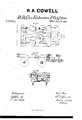
'snbioient to' enable thoseskiiled iu the art to which my vinvention appertains to fully understand and to make and use the same, reference being had to the accompanying drawing making' part of this specifica tion, andnwhich- Figure l is a plan View. Figure 2 is a longitudinal section. Figure is an end View.. c Y Like. letters of reference indicate like parts in the various gures. Elly-invention'consists in the peculiar-rconstruction". and arrangement of the parts as hereinafter fully described and claimed, whereby a much improved, safe, and strong,r car is made, capable of resisting,y a very great shock. It also leaves no open space between cnrs, endangering the lives of persons by slipping and Falling between them.
Referring to the drawing- A Arepresent the two .side rails of the platform or" va car, and V B I5 are intermediate rails, all lying lengthwise of tbe ear, the side railsA A being shorter and terrnim" ati-ug at the end of the bouse or body of the car, while the intermediate rails B B are longer and ex tend beyond 'the body of the car `to form the platbrm.
The end sill C, forming the end of the oar proper, is made by square blocks fitted between the rails B base or..
' B, and having a strong bolt, o, passing through tliem and vtherails, und secured by nntsc ou the outside face ofthe side rails A A. There are also heavy planks (l d placed across, .one
- on the upper side andone on the under side 0f the blocks andrails. rlhis makes the end offthe frame quite as 'strong as the sides andallows the rails B B to extend beyond, for reasons hereinafter-shown.
Across the end of the rails B B is a cross-head, D. The floor and steps of the platform are made of' a plate of sheet-boiler iron, E. bent -to form the steps,.'
and roughened on the upper side sons not to be slippery- 4 A piece of iron,"ll", is 'bent so as to embrace the cross-head D,"as seen in fig.- 2, thus forming the extension-platfbrm.
The upper side is slipped in under the floor-plate E, and a slot, f, is out in Vboth the upper and lower parts, through which and. the' crossdiead a bolt, t', passes. l f
The iron F extends out beyond thev cross-head a as `follows pass from h and 71,
short distaneemnndthe spacebetween' its outer end and the cross-ead D is occupied byu rubber spring, o, which acts to keep the iron extended, and will also allowitlto turn sidewise a little to conform1 to the c urve in which two carsmay be in'. y
This piece of iron E is as wide as the space between the hand-rails of the platform, andthe two (one on each car) meet and cover the space. usually Vfound between the oars.
.The draw-head G is secured at its rear end in its usual manner, but the front end secure by'braoes,
A hearyiron rod, h, is bent, as seen. in lig. 3,and nearly embraces the bumper, the ends being secured' in the ends of the cross-head D. Y
A bar, h', under the bumper, unites wth'the braces at 't/fgtnd tbus secures the bumper irmly 1u its place. G
The two bars j j, extending yfromthe joints la. it", to thecros's-head l), will prevent-the bumper being forced upward.
There are also two strong iron braces, K K, which at the front of the bumper back crei-'the sill C to a transom, m, to both of uf'hichthey are firmly secured.-
By this inode of constructing a platform greater strengthis obtained. By having,r the rails B B extend outetothe cross-head D o r front end of the platfbrnx, audby'having the platform oor and steps of iron' and the brace-rods K K arranged asV .shown 'the liability o'the oars breaking into'each other or telescopu ing, as it is termed, in cases of collisions, is overcome,
as the timbers forming the base o r foundation would come' in Contact directly end to end'.
The plates F,.forming the extension-platnfm in two contiguous cars, also touch each other at all times, so that thespace between two cars is always closed. "lhe point of meeting of lthe two extension-plat forms is over the central partei' arubber bulb, n, on the link between the two draw-heads.
ThedraW-hends or couplings (a former invention of' mine) are designed to work in conjunction with this," my improved extensiomplatfornn "I clairn .rods h It, @correcting bar h', and upright supports jj,
with the vdrawhhead G, substantially'nsshown,and for the purpose set forth.
BLA. GOWELL. Witnesses:
" GEo. WV.. T'nsnrrrs,
L M. Hnnnnnso" 1. The combination and arrangement oi' the rails'
Publications (1)
| Publication Number | Publication Date |
|---|---|
| US110901A true US110901A (en) | 1871-01-10 |
Family
ID=2180370
Family Applications (1)
| Application Number | Title | Priority Date | Filing Date |
|---|---|---|---|
| US110901D Expired - Lifetime US110901A (en) | Eensbelaee a |
Country Status (1)
| Country | Link |
|---|---|
| US (1) | US110901A (en) |
Cited By (5)
| Publication number | Priority date | Publication date | Assignee | Title |
|---|---|---|---|---|
| US20050037424A1 (en) * | 2003-08-13 | 2005-02-17 | Schembri Carol T. | Selectable length linear microarrays |
| US20050084866A1 (en) * | 2003-10-15 | 2005-04-21 | Caren Michael P. | Methods and apparatus for sample mixing |
| US20050083781A1 (en) * | 2003-10-15 | 2005-04-21 | Caren Michael P. | Methods and apparatus for mixing of liquids |
| US20050084867A1 (en) * | 2003-10-15 | 2005-04-21 | Caren Michael P. | Hybridization and scanning apparatus |
| US20060075621A1 (en) * | 2003-12-29 | 2006-04-13 | Pilling Weck Incorporated | Ratcheting driver with pivoting pawls and method of arranging same |
-
0
- US US110901D patent/US110901A/en not_active Expired - Lifetime
Cited By (6)
| Publication number | Priority date | Publication date | Assignee | Title |
|---|---|---|---|---|
| US20050037424A1 (en) * | 2003-08-13 | 2005-02-17 | Schembri Carol T. | Selectable length linear microarrays |
| US20050084866A1 (en) * | 2003-10-15 | 2005-04-21 | Caren Michael P. | Methods and apparatus for sample mixing |
| US20050083781A1 (en) * | 2003-10-15 | 2005-04-21 | Caren Michael P. | Methods and apparatus for mixing of liquids |
| US20050084867A1 (en) * | 2003-10-15 | 2005-04-21 | Caren Michael P. | Hybridization and scanning apparatus |
| US20060075621A1 (en) * | 2003-12-29 | 2006-04-13 | Pilling Weck Incorporated | Ratcheting driver with pivoting pawls and method of arranging same |
| US7421772B2 (en) | 2003-12-29 | 2008-09-09 | Teleflex Medical Incorporated | Ratcheting driver with pivoting pawls and method of arranging same |
Similar Documents
| Publication | Publication Date | Title |
|---|---|---|
| US110901A (en) | Eensbelaee a | |
| US3450A (en) | t elisha | |
| US6730A (en) | lewis | |
| USRE4846E (en) | Improvement in railway-car platforms | |
| US83907A (en) | Improved car-coupling | |
| US266897A (en) | Eben b | |
| US68327A (en) | Improved cabrplatfoem | |
| US777953A (en) | Bumper for cars. | |
| US109347A (en) | Improvement in railway-car bumpers and draw-heads | |
| US150031A (en) | Improvement in car-couplings | |
| US395014A (en) | Car-platform | |
| US82708A (en) | Improved oae-couplisg | |
| US846846A (en) | Railway-car. | |
| US601900A (en) | mokeen | |
| US135716A (en) | Improvement in safety-trucks for railroad cars | |
| US122814A (en) | Improvement in hand-cars | |
| US8451A (en) | Of railroad-cars | |
| US824125A (en) | Combination truss-rod stand and anchor-bracket. | |
| US508362A (en) | Nvkktor | |
| US95711A (en) | Improved rail wat-car coupling | |
| US754688A (en) | Car-platform. | |
| US300937A (en) | Joseph p | |
| US313461A (en) | Jacob yolk | |
| US119766A (en) | Improvement in railway-car safety apparatus | |
| US634218A (en) | Car construction. |