US11088639B2 - Motor driving device and method thereof - Google Patents
Motor driving device and method thereof Download PDFInfo
- Publication number
- US11088639B2 US11088639B2 US16/720,504 US201916720504A US11088639B2 US 11088639 B2 US11088639 B2 US 11088639B2 US 201916720504 A US201916720504 A US 201916720504A US 11088639 B2 US11088639 B2 US 11088639B2
- Authority
- US
- United States
- Prior art keywords
- signal
- motor
- output
- input signal
- commutation
- Prior art date
- Legal status (The legal status is an assumption and is not a legal conclusion. Google has not performed a legal analysis and makes no representation as to the accuracy of the status listed.)
- Active
Links
- 238000000034 method Methods 0.000 title claims description 47
- 238000013459 approach Methods 0.000 claims description 6
- 101100263683 Saccharomyces cerevisiae (strain ATCC 204508 / S288c) VHS1 gene Proteins 0.000 description 15
- 238000010586 diagram Methods 0.000 description 6
- 238000001514 detection method Methods 0.000 description 5
- 238000004519 manufacturing process Methods 0.000 description 4
- 238000012986 modification Methods 0.000 description 4
- 230000004048 modification Effects 0.000 description 4
- 239000013256 coordination polymer Substances 0.000 description 3
- 230000008901 benefit Effects 0.000 description 2
- 101100263684 Saccharomyces cerevisiae (strain ATCC 204508 / S288c) VHS2 gene Proteins 0.000 description 1
- 238000006243 chemical reaction Methods 0.000 description 1
- 238000004891 communication Methods 0.000 description 1
- 230000007257 malfunction Effects 0.000 description 1
Images


Classifications
-
- H—ELECTRICITY
- H02—GENERATION; CONVERSION OR DISTRIBUTION OF ELECTRIC POWER
- H02P—CONTROL OR REGULATION OF ELECTRIC MOTORS, ELECTRIC GENERATORS OR DYNAMO-ELECTRIC CONVERTERS; CONTROLLING TRANSFORMERS, REACTORS OR CHOKE COILS
- H02P6/00—Arrangements for controlling synchronous motors or other dynamo-electric motors using electronic commutation dependent on the rotor position; Electronic commutators therefor
- H02P6/14—Electronic commutators
- H02P6/15—Controlling commutation time
- H02P6/153—Controlling commutation time wherein the commutation is advanced from position signals phase in function of the speed
-
- H—ELECTRICITY
- H02—GENERATION; CONVERSION OR DISTRIBUTION OF ELECTRIC POWER
- H02P—CONTROL OR REGULATION OF ELECTRIC MOTORS, ELECTRIC GENERATORS OR DYNAMO-ELECTRIC CONVERTERS; CONTROLLING TRANSFORMERS, REACTORS OR CHOKE COILS
- H02P6/00—Arrangements for controlling synchronous motors or other dynamo-electric motors using electronic commutation dependent on the rotor position; Electronic commutators therefor
- H02P6/14—Electronic commutators
- H02P6/16—Circuit arrangements for detecting position
- H02P6/18—Circuit arrangements for detecting position without separate position detecting elements
Definitions
- the present disclosure relates to a motor driving device and method, and more particularly to a motor driving device and method for resisting noises and suitable for weak magnetic or weak back electromotive force.
- Direct current (DC) brushless motors are common motors that have advantages of high efficiency, lightness, thinness, shortness, and smallness, and thus are widely used in various fields.
- DC brushless motors are widely used.
- fan motors for various electronic products and spindle motors for computer storage devices utilize the DC brushless motors.
- a position of a rotor of the motor must be detected to properly drive commutation switches for performing a commutation procedure.
- the existing brushless DC motor system typically includes a three-phase brushless DC motor, a Hall sensor, and a driver.
- the Hall sensor is prone to misjudge time points of commutation under weak magnetic force, or since a hysteresis voltage of a hysteresis comparator used for detection during operation is as the same as a hysteresis voltage used in a starting mode, thereby causing the commutation falls behind.
- the Hall sensor is easily affected by external environments, a sensing accuracy may be lowered, and may even malfunction in some environments (for example, an environment with an excessive temperature).
- the brushless DC motor system further includes the Hall sensor, and a volume of the system and manufacturing costs are therefore increased. Therefore, a sensorless driving method without using a sensor is further proposed.
- the present disclosure provides a motor driving device and method capable of performing commutation detection using different hysteresis voltages in a start state and an operating state according to an operating condition of a motor.
- the present disclosure provides a motor driving device for driving a motor
- the motor driving device includes a first hysteresis comparator, a second hysteresis comparator, a logic circuit, a control unit, and an inverter circuit.
- the first hysteresis comparator has a first hysteresis voltage and is configured to compare a first input signal with a second input signal, and correspondingly output a first output signal according to a comparison result.
- the second hysteresis comparator has a second hysteresis voltage and is configured to compare the first input signal with the second input signal, and correspondingly output a second output signal according to a comparison result.
- the logic circuit is configured to: receive a start signal or a start completion signal to output the first output signal as a commutation signal according to the start signal, or to output the second output signal as the commutation signal according to the start completion signal; clamp the second output signal by the first output signal; stop outputting the commutation signal after the potential state of the commutation signal is changed; and release a clamping on the second output signal by the first output signal and output the commutation signal in response to a difference voltage between the first input signal and the second input signal being greater than a positive value of the first hysteresis voltage or less than a negative value of the first hysteresis voltage.
- the control unit is configured to generate a driving signal according to the commutation signal, and determine whether the motor is started according to a driving condition of the motor to determine whether to output the start signal or the start completion signal.
- the inverter circuit is configured to control a plurality of phase circuits of the motor according to the drive signal to drive the motor.
- the first hysteresis voltage is greater than the second hysteresis voltage.
- the motor driving device further includes a motor parameter detecting module configured to detect a plurality of operating parameters of the motor and correspondingly output a plurality of parameter signals, wherein the control unit is configured to determine the operating condition of the motor according to the driving condition of the motor to determine whether to output the start signal or the start completion signal.
- a motor parameter detecting module configured to detect a plurality of operating parameters of the motor and correspondingly output a plurality of parameter signals
- the control unit is configured to determine the operating condition of the motor according to the driving condition of the motor to determine whether to output the start signal or the start completion signal.
- the logic circuit is configured to control the first hysteresis comparator to raise the first hysteresis voltage when receiving the starting completion signal.
- the second hysteresis voltage approaches zero.
- the motor driving device further includes a Hall sensor configured to detect a rotor position of the motor and generate a Hall signal group including the first input signal and the second input signal.
- the motor driving device further includes a floating phase circuit configured to select a floating phase of the motor that is not turned on, and output a floating phase signal as the first input signal, wherein the second input signal is provided from a reference voltage source.
- the present disclosure provides a motor driving device for driving a motor
- the motor driving device includes a hysteresis comparator, a logic circuit, a control unit, and an inverter circuit.
- the hysteresis comparator has a hysteresis voltage and is configured to compare a first input signal with a second input signal, and correspondingly output a first output signal according to a comparison result.
- the logic circuit is configured to: receive a start signal or a start completion signal to output the first output signal as a commutation signal according to the start signal, or to control the hysteresis comparator to reduce the hysteresis voltage and output the first output signal as the commutation signal according to the start completion signal.
- the control unit is configured to generate a driving signal according to the commutation signal, and determine whether the motor is started according to a driving condition of the motor to determine whether to output the start signal or the start completion signal.
- the inverter circuit is configured to control a plurality of phase circuits of the motor according to the drive signal to drive the motor.
- the motor driving device further includes a motor parameter detecting module configured to detect a plurality of operating parameters of the motor and correspondingly output a plurality of parameter signals, wherein the control unit is configured to determine the operating condition of the motor according to the driving condition of the motor to determine whether to output the start signal or the start completion signal.
- a motor parameter detecting module configured to detect a plurality of operating parameters of the motor and correspondingly output a plurality of parameter signals
- the control unit is configured to determine the operating condition of the motor according to the driving condition of the motor to determine whether to output the start signal or the start completion signal.
- the motor driving device further includes a Hall sensor configured to detect a rotor position of the motor and generate a Hall signal group including the first input signal and the second input signal.
- the motor driving device further includes a floating phase circuit configured to select a floating phase of the motor that is not turned on, and output a floating phase signal as the first input signal, wherein the second input signal is provided from a reference voltage source.
- the present disclosure provides a motor driving method for driving a motor, the motor driving method includes the following steps: configuring a first hysteresis comparator having a first hysteresis voltage to compare a first input signal with a second input signal, and correspondingly output a first output signal according to a comparison result; configuring a second hysteresis comparator having a second hysteresis voltage to compare the first input signal with the second input signal, and correspondingly output a second output signal according to a comparison result; configuring a logic circuit to: receive a start signal or a start completion signal to output the first output signal as a commutation signal according to the start signal, or to output the second output signal as the commutation signal according to the start completion signal; clamp the second output signal by the first output signal; stop outputting the commutation signal after the potential state of the commutation signal is changed; and release a clamping on the second output signal by the first output signal and output the com
- the motor driving method further includes: configuring a motor parameter detecting module to detect a plurality of operating parameters of the motor and correspondingly output a plurality of parameter signals; and configuring the control unit to determine the operating condition of the motor according to the driving condition of the motor to determine whether to output the start signal or the start completion signal.
- the motor driving method further includes: configuring the logic circuit to control the first hysteresis comparator to raise the first hysteresis voltage when receiving the starting completion signal.
- the second hysteresis voltage approaches zero.
- the motor driving method further includes configuring a Hall sensor to detect a rotor position of the motor and generate a Hall signal group including the first input signal and the second input signal.
- the motor driving method further includes: configuring a floating phase circuit to select a floating phase of the motor that is not turned on, and output a floating phase signal as the first input signal; and configuring a reference voltage source to output the second input signal.
- the present disclosure provides a motor driving method for driving a motor, and the motor driving method includes the following steps: configuring a hysteresis comparator having a hysteresis voltage to compare a first input signal with a second input signal, and correspondingly output a first output signal according to a comparison result; configuring a logic circuit to: receive a start signal or a start completion signal to output the first output signal as a commutation signal according to the start signal, or to control the hysteresis comparator to reduce the hysteresis voltage and output the first output signal as the commutation signal according to the start completion signal; configuring a control unit to generate a driving signal according to the commutation signal, and determine whether the motor is started according to a driving condition of the motor to determine whether to output the start signal or the start completion signal; and configuring an inverter circuit to control a plurality of phase circuits of the motor according to the drive signal to drive the motor.
- the motor driving method further includes: configuring a motor parameter detecting module to detect a plurality of operating parameters of the motor, and correspondingly outputting a plurality of parameter signals; and configuring the control unit to determine the operating parameter according to the operating parameters The operating condition of the motor to determine whether to output the start signal or the start completion signal.
- the motor driving method further includes configuring a Hall sensor to detect a rotor position of the motor and generate a Hall signal group including the first input signal and the second input signal.
- the motor driving method further includes: configuring a floating phase circuit to select a floating phase of the motor that is not turned on, and output a floating phase signal as the first input signal, wherein the second input signal is provided from a reference voltage source.
- the motor driving device and method provided by the present disclosure can utilize different hysteresis voltages respectively in a start state and an operating state according to an operating condition of the motor, thereby preventing the Hall sensor from misjudging the time points of commutation under weak magnetic force. Further, the commutation point can be prevented from falling behind in the operating state by using a hysteresis voltage different from that in the starting state.
- the motor driving device and method provided by the present disclosure can resist noise in the start state and improve an efficiency of the motor in an operating state, while not causing differences being too large in efficiency among samples fabricated in mass production due to weak magnetic force of a magnetic strip or weak back electromotive force.
- FIG. 1 is a circuit schematic diagram of a motor driving device according to a first embodiment of the present disclosure.
- FIGS. 2A and 2B are timing charts of signals of a start state and a start completion state of the motor drive circuit according to the first embodiment of the present disclosure.
- FIG. 3 is another circuit schematic diagram of a motor driving device according to the first embodiment of the present disclosure.
- FIG. 4 is a circuit schematic diagram of a motor driving device according to a second embodiment of the present disclosure.
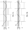
- FIGS. 5A and 5B are timing charts of signals of a start state and a start completion state of the motor drive circuit according to the second embodiment of the present disclosure.
- FIG. 6 is a flow chart showing a motor driving method according to a third embodiment of the present disclosure.
- FIG. 7 is a flow chart showing a motor driving method according to a fourth embodiment of the present disclosure.
- Numbering terms such as “first”, “second” or “third” can be used to describe various components, signals or the like, which are for distinguishing one component/signal from another one only, and are not intended to, nor should be construed to impose any substantive limitations on the components, signals or the like.
- FIG. 1 is a circuit schematic diagram of a motor driving device according to a first embodiment of the present disclosure.
- a first embodiment of the present disclosure provides a motor driving device 1 for driving a motor 11 , which includes a first hysteresis comparator CP 1 , a second hysteresis comparator CP 2 , a logic circuit 10 , a control unit 12 , and an inverter circuit 14 .
- the first hysteresis comparator CP 1 has a first hysteresis voltage VHS 1 , and is configured to compare a first input signal IN 1 with a second input signal IN 2 , and correspondingly output a first output signal according to a comparison result OUT 1 . Specifically, when a voltage difference between the first input signal IN 1 and the second input signal IN 2 is greater than a positive value of the first hysteresis voltage VHS 1 , the first output signal OUT 1 has high potential. When the voltage difference between the first input signal IN 1 and the second input signal IN 2 is less than a negative value of the first hysteresis voltage VHS 1 , the first output signal OUT 1 has low potential.
- the second hysteresis comparator CP 2 has a second hysteresis voltage VHS 2 and is configured to compare the first input signal IN 1 with the second input signal IN 2 , and correspondingly output a second output signal OUT 2 according to a comparison result.
- the second hysteresis voltage approaches zero.
- the logic circuit 10 is configured to receive a start signal S 3 or a start completion signal S 4 , and operate in two modes.
- the logic circuit 10 uses the first output signal OUT 1 as a commutation signal S 1 to be output.
- the logic circuit 10 receives the start completion signal S 4 , the second output signal OUT 2 is used as the commutation signal S 1 to be output, and the logic circuit 10 clamps the second output signal OUT 2 by the first output signal OUT 1 .
- the logic circuit 10 is configured to stop outputting the commutation signal S 1 after a potential state of the commutation signal S 1 is changed, release a clamping on the second output signal OUT 2 by the first output signal OUT 1 and output the commutation signal S 1 in response to a difference voltage between the first input signal IN 1 and the second input signal IN 2 being greater than a positive value of the first hysteresis voltage VHS 1 or less than a negative value of the first hysteresis voltage VHS 1 .
- the control unit 12 is configured to generate the driving signal S 2 according to the commutation signal S 1 , and determine whether a starting of the motor 11 is completed according to the driving condition of the motor to determine whether to output the start signal S 3 or the start completion signal S 4 .
- the inverter circuit 14 is configured to control a plurality of phase circuits of the motor 11 in accordance with the driving signal S 2 to drive the motor 11 .
- the first hysteresis voltage VHS 1 is greater than the second hysteresis voltage VH 2 .
- FIGS. 2A and 2B are timing charts of signals of a start state and a start completion state of the motor drive circuit according to the first embodiment of the present disclosure.
- the first output signal OUT 1 is used as the commutation signal S 1 and output in the start state.
- the commutation signal S 1 is converted from the low potential to the high potential.
- the difference voltage between the first input signal IN 1 and the second input signal IN 2 is less than the negative value of the first hysteresis voltage VHS 1
- the commutation signal S 1 is converted from the high potential to the low potential.
- the logic circuit 10 uses the second output signal OUT 2 as the commutation signal to be output, and clamps the second output signal OUT 2 by the first output signal OUT 1 , which forms clamp regions as shown in FIG. 2B .
- the logic circuit 10 is configured to stop outputting the commutation signal S 1 after a potential state of the commutation signal S 1 is changed, release a clamping on the second output signal OUT 2 by the first output signal OUT 1 and output the second output signal OUT 2 as the commutation signal S 1 in response to a difference voltage between the first input signal IN 1 and the second input signal IN 2 being greater than the positive value of the first hysteresis voltage VHS 1 or less than the negative value of the first hysteresis voltage VHS 1 .
- the second hysteresis voltage approaches 0, therefore, after the difference voltage between the first input signal IN 1 and the second input signal IN 2 is greater than the positive value of the first hysteresis voltage VHS 1 or less than the negative value of the first hysteresis voltage VHS 1 , the commutation signal S 1 can perform high-low potential conversion as a reference for the control unit 12 to generate the driving signal S 2 .
- the logic circuit 10 controls the first hysteresis comparator CP 1 to raise the first hysteresis voltage VHS 1 in response to receiving the start completion signal S 4 .
- FIG. 3 is another circuit schematic diagram of a motor driving device according to the first embodiment of the present disclosure.
- the motor driving device 1 further includes a motor parameter detecting module 13 configured to detect a plurality of operating parameters of the motor 11 and correspondingly output a plurality of parameter signals S 5 .
- the control unit 12 is configured to determine the operating condition of the motor 11 according to the driving condition of the motor 11 to determine whether to output the start signal S 3 or the start completion signal S 4 .
- the motor parameter detecting module 13 can be a rotation speed detector. When the control unit 12 determines that the rotation speed of the motor 11 exceeds a predetermined rotation speed, it is determined that the starting of the motor 11 is complete, and the control unit 12 outputs the start completion signal S 4 .
- the start signal S 3 and the start completion signal S 4 can be represented by high and low potentials in the same signal, and the present disclosure is not limited thereto.
- the motor driving device 1 may include a Hall sensor 15 configured to detect a rotor position of the motor 11 and generate a Hall signal group HAL including the first input signal IN 1 and the second input signal IN 2 .
- the inverter circuit 14 can include a plurality of upper and lower bridge switch groups, the number of which corresponds to the number of phase circuits of the motor 11 .
- the motor driving device 1 can further include a floating phase circuit 16 configured to select a floating phase of the motor 11 that is not turned on, and output a floating phase signal as the first input signal IN 1 .
- the second input signal IN 2 is provided from a reference voltage source, for example, a common voltage source COM, 0.5 times of an inter-chip voltage VDD, or the ground GND.
- the motor driving device 1 can utilize different hysteresis voltages respectively in the start state and the operating state according to an operating condition of the motor, thereby preventing the Hall sensor from misjudging the time points of commutation under weak magnetic force. Further, commutation points can be prevented from falling behind in the operating state by using a hysteresis voltage different from that in the starting state. In addition, the motor driving device 1 can resist noise in the start state and improve an efficiency of the motor in an operating state, while not causing differences being too large in efficiency among samples fabricated in mass production due to weak magnetic force of a magnetic strip or weak back electromotive force.
- FIG. 4 is a circuit schematic diagram of a motor driving device according to a second embodiment of the present disclosure.
- a second embodiment of the present disclosure provides a motor driving device 1 for driving a motor 11 , which includes a hysteresis comparator CP, a logic circuit 10 , a control unit 12 , and an inverter circuit 14 .
- the hysteresis comparator CP has a hysteresis voltage VHS, and is configured to compare a first input signal IN 1 with a second input signal IN 2 , and correspondingly output an output signal OUT according to a comparison result.
- the logic circuit 10 is configured to receive a start signal S 3 or a start completion signal S 4 to output the output signal OUT as a commutation signal S 1 according to the start signal S 3 , or to control the hysteresis comparator CP to reduce the hysteresis voltage VHS and output the output signal OUT as the commutation signal S 1 according to the start completion signal S 4 .
- control unit 12 The operational details of the control unit 12 and the inverter circuit 14 are the same as those of the first embodiment, and the repeated descriptions are omitted hereinafter.
- FIGS. 5A and 5B are timing charts of signals of a start state and a start completion state of the motor drive circuit according to the second embodiment of the present disclosure.
- FIG. 5A which shows that the output signal OUT is used as the commutation signal S 1 and output in the start state.
- the commutation signal S 1 is converted from the low potential to the high potential.
- the difference voltage between the first input signal IN 1 and the second input signal IN 2 is less than the negative value of the hysteresis voltage VHS, the commutation signal S 1 is converted from the high potential to the low potential.
- the hysteresis voltage VHS is reduced to the hysteresis voltage VHS′.
- the difference voltage between the first input signal IN 1 and the second input signal IN 2 is greater than the positive value of the hysteresis voltage VHS 1 , the commutation signal S 1 is converted from the low potential to the high potential.
- the difference voltage between the first input signal IN 1 and the second input signal IN 2 is less than the negative value of the hysteresis voltage VHS, the commutation signal S 1 is converted from the high potential to the low potential.
- the motor parameter detection module, the Hall sensor, and the floating phase circuit can also be configured according to the type of the motor. Details thereof have been described in the first embodiment, and thus are not described hereinafter.
- FIG. 6 is a flow chart showing a motor driving method according to a third embodiment of the present disclosure.
- a third embodiment of the present disclosure provides a motor driving method applicable to the motor driving device of the first embodiment described above, but is not limited thereto, and the repeated descriptions of the operational details of the components of the motor driving device will be omitted for convenience of explanation.
- the motor driving method includes the following steps:
- Step S 100 configuring a first hysteresis comparator having a first hysteresis voltage to compare a first input signal with a second input signal, and correspondingly output a first output signal according to a comparison result.
- Step S 101 configuring a first hysteresis comparator having a first hysteresis voltage to compare a first input signal with a second input signal, and correspondingly output a first output signal according to a comparison result.
- Step S 102 configuring a logic circuit to receive a start signal or a start completion signal.
- step S 103 configuring the logic circuit to output the first output signal as a commutation signal according to the start signal.
- step S 104 configuring the logic circuit to output the second output signal as the commutation signal according to the start completion signal, clamp the second output signal by the first output signal, stop outputting the commutation signal after the potential state of the commutation signal is changed, and release the clamping on the second output signal by the first output signal and output the commutation signal in response to a difference voltage between the first input signal and the second input signal being greater than a positive value of the first hysteresis voltage or less than a negative value of the first hysteresis voltage.
- Step S 105 configuring a control unit to generate a driving signal according to the commutation signal, and determine whether the motor is started according to a driving condition of the motor to determine whether to output the start signal or the start completion signal.
- Step S 106 configuring an inverter circuit to control a plurality of phase circuits of the motor according to the drive signal to drive the motor.
- the first hysteresis voltage is greater than the second hysteresis voltage.
- FIG. 7 is a flow chart showing a motor driving method according to a fourth embodiment of the present disclosure.
- a fourth embodiment of the present disclosure provides a motor driving method applicable to the motor driving device of the first embodiment described above, but is not limited thereto, and the repeated descriptions of the operational details of the components of the motor driving device will be omitted for convenience of explanation.
- the motor driving method includes the following steps:
- Step S 200 configuring a hysteresis comparator having a hysteresis voltage to compare a first input signal with a second input signal, and correspondingly output an output signal according to a comparison result.
- Step S 201 configuring a logic circuit to receive a start signal or a start completion signal.
- step S 202 configuring the logic circuit to output the output signal as a commutation signal according to the start signal.
- step S 203 configuring the logic circuit to control the hysteresis comparator to reduce the hysteresis voltage and output the output signal as the commutation signal according to the start completion signal.
- Step S 204 configuring a control unit to generate a driving signal according to the commutation signal, and determine whether the motor is started according to a driving condition of the motor to determine whether to output the start signal or the start completion signal.
- Step S 205 configuring an inverter circuit to control a plurality of phase circuits of the motor according to the drive signal to drive the motor.
- the motor driving device and method provided by the present disclosure can utilize different hysteresis voltages respectively in a start state and an operating state according to an operating condition of the motor, thereby preventing the Hall sensor from misjudging the time points of commutation under weak magnetic force. Further, the commutation point can be prevented from falling behind in the operating state by using a hysteresis voltage different from that in the starting state.
- the motor driving device and method provided by the present disclosure can resist noise in the start state and improve an efficiency of the motor in an operating state, while not causing differences being too large in efficiency among samples fabricated in mass production due to weak magnetic force of a magnetic strip or weak back electromotive force.
Landscapes
- Engineering & Computer Science (AREA)
- Power Engineering (AREA)
- Control Of Motors That Do Not Use Commutators (AREA)
Abstract
Description
Claims (20)
Applications Claiming Priority (2)
| Application Number | Priority Date | Filing Date | Title |
|---|---|---|---|
| TW108132855 | 2019-09-11 | ||
| TW108132855A TWI692195B (en) | 2019-09-11 | 2019-09-11 | Motor driving device and method thereof |
Publications (2)
| Publication Number | Publication Date |
|---|---|
| US20210075346A1 US20210075346A1 (en) | 2021-03-11 |
| US11088639B2 true US11088639B2 (en) | 2021-08-10 |
Family
ID=71134538
Family Applications (1)
| Application Number | Title | Priority Date | Filing Date |
|---|---|---|---|
| US16/720,504 Active US11088639B2 (en) | 2019-09-11 | 2019-12-19 | Motor driving device and method thereof |
Country Status (3)
| Country | Link |
|---|---|
| US (1) | US11088639B2 (en) |
| CN (1) | CN112491307B (en) |
| TW (1) | TWI692195B (en) |
Families Citing this family (4)
| Publication number | Priority date | Publication date | Assignee | Title |
|---|---|---|---|---|
| TWI766351B (en) * | 2020-08-27 | 2022-06-01 | 茂達電子股份有限公司 | Motor driving circuit and method thereof |
| TWI760915B (en) * | 2020-11-05 | 2022-04-11 | 致新科技股份有限公司 | Motor controller |
| US11290037B1 (en) | 2020-11-06 | 2022-03-29 | Global Mixed-Mode Technology Inc. | Motor controller |
| CN114050746B (en) * | 2021-11-11 | 2024-02-02 | 成都芯进电子有限公司 | Gain control system and method for single-phase sine wave DC brushless motor driving chip |
Citations (1)
| Publication number | Priority date | Publication date | Assignee | Title |
|---|---|---|---|---|
| US20150274099A1 (en) * | 2012-10-02 | 2015-10-01 | Technoboost | Power supply unit for supplying power to an on-board electrical network of a vehicle |
Family Cites Families (15)
| Publication number | Priority date | Publication date | Assignee | Title |
|---|---|---|---|---|
| AU2003903787A0 (en) * | 2003-07-22 | 2003-08-07 | Sergio Adolfo Maiocchi | A system for operating a dc motor |
| CN1324799C (en) * | 2004-06-03 | 2007-07-04 | 旺玖科技股份有限公司 | Low Noise DC Motor Driver IC |
| TW200614649A (en) * | 2004-10-20 | 2006-05-01 | Apollo Technology Inc | Dc brushless motor driver with chip powered through output terminals |
| CN201238280Y (en) * | 2008-08-12 | 2009-05-13 | 普诚科技股份有限公司 | Motor driving device |
| CN101800511B (en) * | 2009-02-11 | 2012-07-25 | 晶致半导体股份有限公司 | Single-phase motor drives with energy-saving modules |
| DE102009028170A1 (en) * | 2009-07-31 | 2011-02-10 | Robert Bosch Gmbh | Commutated electric drive and method for controlling a commutated electric motor |
| TWI399031B (en) * | 2009-08-19 | 2013-06-11 | Delta Electronics Inc | Motor control apparatus and method thereof |
| CN101997465B (en) * | 2009-08-21 | 2013-11-13 | 台达电子工业股份有限公司 | Motor control device |
| CN102931893B (en) * | 2011-08-09 | 2015-03-11 | 尼克森微电子股份有限公司 | Soft switching control circuit of DC motor |
| CN104040873B (en) * | 2012-01-25 | 2017-03-22 | 松下电器产业株式会社 | Motor drive device and refrigerator utilizing same |
| KR102227315B1 (en) * | 2014-07-08 | 2021-03-12 | 인텔 코포레이션 | A negative differential resistance based memory |
| US9444384B2 (en) * | 2014-07-16 | 2016-09-13 | Atieva, Inc. | Direct torque control motor controller with transient current limiter |
| KR20160016435A (en) * | 2014-08-05 | 2016-02-15 | 삼성전기주식회사 | Apparatus and method for mortor driving |
| TWI538383B (en) * | 2015-05-22 | 2016-06-11 | 茂達電子股份有限公司 | Motor driving circuit |
| CN108322106A (en) * | 2018-02-27 | 2018-07-24 | 牟特科技(北京)有限公司 | A kind of method and device of DC brushless motor commutation |
-
2019
- 2019-09-11 TW TW108132855A patent/TWI692195B/en active
- 2019-09-24 CN CN201910905939.5A patent/CN112491307B/en active Active
- 2019-12-19 US US16/720,504 patent/US11088639B2/en active Active
Patent Citations (1)
| Publication number | Priority date | Publication date | Assignee | Title |
|---|---|---|---|---|
| US20150274099A1 (en) * | 2012-10-02 | 2015-10-01 | Technoboost | Power supply unit for supplying power to an on-board electrical network of a vehicle |
Also Published As
| Publication number | Publication date |
|---|---|
| TW202112049A (en) | 2021-03-16 |
| CN112491307B (en) | 2022-06-28 |
| TWI692195B (en) | 2020-04-21 |
| US20210075346A1 (en) | 2021-03-11 |
| CN112491307A (en) | 2021-03-12 |
Similar Documents
| Publication | Publication Date | Title |
|---|---|---|
| US10972024B1 (en) | Motor driving device and method | |
| US11088639B2 (en) | Motor driving device and method thereof | |
| CN104321656B (en) | Method and controller for an electric motor with fault detection | |
| CN101983322B (en) | Temperature detecting circuit | |
| US11088641B2 (en) | Motor driving device having lock protection mode | |
| US8154233B2 (en) | Sensorless method and related device for starting a three-phase brushless direct-current motor | |
| US8049448B2 (en) | Control circuit with dual programmable feedback loops for BLDC motors | |
| US10199974B2 (en) | Motor driving circuit and motor driving method | |
| US9577566B2 (en) | Motor driving circuit | |
| US11205984B1 (en) | Motor driving circuit and motor driving method | |
| US12095404B2 (en) | Motor forward and reverse rotation detector and motor driver having motor forward and reverse rotation detector | |
| Heo et al. | Integrated sliding‐mode sensorless driver with pre‐driver and current sensing circuit for accurate speed control of PMSM | |
| CN224021607U (en) | A Si Hall magnetic switch and an IPM detection system based on the Si Hall magnetic switch | |
| US12034394B2 (en) | Motor driver using correcting mechanism on sensed motor position | |
| CN115459666B (en) | Permanent magnet synchronous motor, speed estimation method thereof, and air conditioner | |
| US11601035B2 (en) | Motor current controlling circuit having voltage detection mechanism | |
| US11362607B1 (en) | Motor unit | |
| US11258381B1 (en) | Driving circuit for single phase motor and driving method for the same | |
| US20250317079A1 (en) | Bldc motor system with reduced power loss and the initial rotation direction judging method thereof | |
| US11290037B1 (en) | Motor controller | |
| CN119966181A (en) | A Si Hall magnetic switch and an IPM detection system based on the Si Hall magnetic switch | |
| WO2026048321A1 (en) | Motor control device and motor control method | |
| JP4445821B2 (en) | Current polarity detection circuit and semiconductor device having the same | |
| JP2005261143A (en) | Sensorless control method and apparatus of brushless motor |
Legal Events
| Date | Code | Title | Description |
|---|---|---|---|
| AS | Assignment |
Owner name: ANPEC ELECTRONICS CORPORATION, TAIWAN Free format text: ASSIGNMENT OF ASSIGNORS INTEREST;ASSIGNORS:CHEN, KUN-MIN;LU, CHING-SHAN;CHIEN, SHIH-HAI;REEL/FRAME:051331/0718 Effective date: 20191218 |
|
| FEPP | Fee payment procedure |
Free format text: ENTITY STATUS SET TO UNDISCOUNTED (ORIGINAL EVENT CODE: BIG.); ENTITY STATUS OF PATENT OWNER: SMALL ENTITY |
|
| FEPP | Fee payment procedure |
Free format text: ENTITY STATUS SET TO SMALL (ORIGINAL EVENT CODE: SMAL); ENTITY STATUS OF PATENT OWNER: SMALL ENTITY |
|
| STPP | Information on status: patent application and granting procedure in general |
Free format text: RESPONSE TO NON-FINAL OFFICE ACTION ENTERED AND FORWARDED TO EXAMINER |
|
| STPP | Information on status: patent application and granting procedure in general |
Free format text: NOTICE OF ALLOWANCE MAILED -- APPLICATION RECEIVED IN OFFICE OF PUBLICATIONS |
|
| STPP | Information on status: patent application and granting procedure in general |
Free format text: PUBLICATIONS -- ISSUE FEE PAYMENT VERIFIED |
|
| STCF | Information on status: patent grant |
Free format text: PATENTED CASE |
|
| MAFP | Maintenance fee payment |
Free format text: PAYMENT OF MAINTENANCE FEE, 4TH YR, SMALL ENTITY (ORIGINAL EVENT CODE: M2551); ENTITY STATUS OF PATENT OWNER: SMALL ENTITY Year of fee payment: 4 |