US11088518B2 - Mounting mechanism for an electrical device - Google Patents
Mounting mechanism for an electrical device Download PDFInfo
- Publication number
- US11088518B2 US11088518B2 US16/151,939 US201816151939A US11088518B2 US 11088518 B2 US11088518 B2 US 11088518B2 US 201816151939 A US201816151939 A US 201816151939A US 11088518 B2 US11088518 B2 US 11088518B2
- Authority
- US
- United States
- Prior art keywords
- mounting
- fin
- wall
- drum
- mounting clamp
- Prior art date
- Legal status (The legal status is an assumption and is not a legal conclusion. Google has not performed a legal analysis and makes no representation as to the accuracy of the status listed.)
- Active
Links
Images


Classifications
-
- H—ELECTRICITY
- H02—GENERATION; CONVERSION OR DISTRIBUTION OF ELECTRIC POWER
- H02G—INSTALLATION OF ELECTRIC CABLES OR LINES, OR OF COMBINED OPTICAL AND ELECTRIC CABLES OR LINES
- H02G3/00—Installations of electric cables or lines or protective tubing therefor in or on buildings, equivalent structures or vehicles
- H02G3/02—Details
- H02G3/08—Distribution boxes; Connection or junction boxes
- H02G3/12—Distribution boxes; Connection or junction boxes for flush mounting
-
- H—ELECTRICITY
- H02—GENERATION; CONVERSION OR DISTRIBUTION OF ELECTRIC POWER
- H02G—INSTALLATION OF ELECTRIC CABLES OR LINES, OR OF COMBINED OPTICAL AND ELECTRIC CABLES OR LINES
- H02G3/00—Installations of electric cables or lines or protective tubing therefor in or on buildings, equivalent structures or vehicles
- H02G3/02—Details
- H02G3/08—Distribution boxes; Connection or junction boxes
- H02G3/081—Bases, casings or covers
- H02G3/083—Inlets
- H02G3/085—Inlets including knock-out or tear-out sections
-
- F—MECHANICAL ENGINEERING; LIGHTING; HEATING; WEAPONS; BLASTING
- F16—ENGINEERING ELEMENTS AND UNITS; GENERAL MEASURES FOR PRODUCING AND MAINTAINING EFFECTIVE FUNCTIONING OF MACHINES OR INSTALLATIONS; THERMAL INSULATION IN GENERAL
- F16M—FRAMES, CASINGS OR BEDS OF ENGINES, MACHINES OR APPARATUS, NOT SPECIFIC TO ENGINES, MACHINES OR APPARATUS PROVIDED FOR ELSEWHERE; STANDS; SUPPORTS
- F16M13/00—Other supports for positioning apparatus or articles; Means for steadying hand-held apparatus or articles
- F16M13/005—Other supports for positioning apparatus or articles; Means for steadying hand-held apparatus or articles integral with the apparatus or articles to be supported
-
- H—ELECTRICITY
- H02—GENERATION; CONVERSION OR DISTRIBUTION OF ELECTRIC POWER
- H02G—INSTALLATION OF ELECTRIC CABLES OR LINES, OR OF COMBINED OPTICAL AND ELECTRIC CABLES OR LINES
- H02G3/00—Installations of electric cables or lines or protective tubing therefor in or on buildings, equivalent structures or vehicles
- H02G3/02—Details
- H02G3/08—Distribution boxes; Connection or junction boxes
- H02G3/081—Bases, casings or covers
-
- H—ELECTRICITY
- H02—GENERATION; CONVERSION OR DISTRIBUTION OF ELECTRIC POWER
- H02G—INSTALLATION OF ELECTRIC CABLES OR LINES, OR OF COMBINED OPTICAL AND ELECTRIC CABLES OR LINES
- H02G3/00—Installations of electric cables or lines or protective tubing therefor in or on buildings, equivalent structures or vehicles
- H02G3/02—Details
- H02G3/08—Distribution boxes; Connection or junction boxes
- H02G3/12—Distribution boxes; Connection or junction boxes for flush mounting
- H02G3/123—Distribution boxes; Connection or junction boxes for flush mounting in thin walls
Definitions
- a typical electrical wall box includes a housing that is installed within a wall.
- An electrical wall box is typically configured to receive at least one electrical device, such as a switch or a receptacle, for example.
- a typical electrical wall box is also configured to receive a wall plate.
- the wall plate may be adapted to cover a yoke plate and/or escutcheon of the electrical devices mounted within the wall box.
- the wall plate may be configured to be attached to the electrical device with or without fasteners.
- Some prior art electrical wall boxes may be mounted to the wall by rear-located clamps that clamp the wall between a flange of the wall box and the clamps.
- the wall boxes may comprise a screw having a head that is located at the front of the wall box and may be driven to pull the clamp towards the flange of the wall box. If terminal ends of the screws opposite the heads are free-floating, the clamps can become dislodged from the wall box and get stuck before completing the clamping action to the wall.
- a mounting mechanism for an apparatus may be configured to mount the apparatus within a wall, for example, in a manner that facilitates secure fastening of the apparatus to the wall.
- the apparatus may comprise an electrical device (e.g., such as a keypad for a load control system) or a wall box in which an electrical device may be mounted.
- the apparatus may include a body having a front surface.
- the body may defines an opening of a wall box configured to receive one or more electrical devices.
- the body may also define an enclosure of an electrical device.
- the body may comprise a flange that at least partially surrounds the body (e.g., the opening of the body) and defines the front surface of the body.
- the apparatus may include one or more mounting screws having a head that may be maintained adjacent to the front surface of the body (e.g., adjacent to the flange) and may extend through a channel formed in the body.
- Each mounting clamp may include a fin and a drum that defines a bore configured to receive the mounting screw.
- Each mounting screw may define a terminal end (e.g., distal from the head) that is configured to extend beyond the mounting clamp and be free-floating.
- the fin may define a front surface.
- the fin of the mounting clamp may be configured to be located in (e.g., received within) a pocket formed in the body.
- the drum may define a foot. The foot may extend beyond the front surface of the fin such that the foot is configured to be located within the channel when the fin is located within the pocket.
- the mounting clamp When the head of the mounting screw is driven, the mounting clamp may be configured to be rotated from the pocket into a position in which the drum of the mounting clamp may be received in the channel.
- the mounting clamp may be configured to rotate from the pocket until a knee of the mounting clamp contacts an edge surface of the pocket.
- the drum of the mounting clamp may be configured to move within the channel as the head of the mounting screw is further driven, and the fin of the mounting clamp may be configured to extend through a gap defined by the channel.
- the drum may be configured to move within the channel until the fin (e.g., the front surface of the fin) abuts the wall such that the wall is clamped between the flange and the fin.
- the gap may be configured to prevent the drum of the mounting clamp from exiting the channel through the gap.
- the gap may define a first width and the channel may define a second width.
- the second width may be greater than the first width such that the mounting clamp is retained within apparatus.
- the mounting clamp may be configured to be driven from the channel to the pocket such that the apparatus is configured to be removed from the wall.
- FIG. 1 is a front perspective view of an example electrical wall box having multiple mounting clamps shown located in pockets.
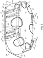
- FIG. 2 is a rear perspective view of the example electrical wall box of FIG. 1 .
- FIG. 3 is a rear perspective view of the example electrical wall box of FIG. 1 with two lower mounting clamps shown in respective pockets and two upper mounting clamps shown in respective channels.
- FIG. 4 is a front view of the example electrical wall box of FIG. 3 .
- FIG. 5 is a top view of the example electrical wall box of FIG. 3 showing the two upper mounting clamps in the channels.
- FIG. 6 is a bottom view of the example electrical wall box of FIG. 3 showing the two lower mounting clamps in the pockets.
- FIG. 7 is a front view of the example electrical wall box of FIG. 3 .
- FIGS. 8A-8F are projection views of one of the mounting clamps of the example electrical wall box of FIG. 1 .
- FIG. 8G is a perspective view of the mounting clamp of FIGS. 8A-8F .
- FIG. 9 is a front perspective view of another example electrical wall box having multiple mounting clamps.
- FIG. 10 is a rear perspective view of the example electrical wall box of FIG. 9 .
- FIGS. 1-7 depict an example electrical wall box 100 .
- the electrical wall box 100 may comprise a body 102 that defines an opening 104 that is configured to receive one or more wall-mounted electrical devices (not shown), such as a dimmer switch or a keypad of a lighting control system.
- the electrical wall box 100 may be configured to be inserted within an opening in a wall (e.g., such as drywall, plaster, wood paneling, etc.).
- the body 102 of the electrical wall box 100 may define a front surface 105 that may be located outside of the wall when the electrical wall box 100 is inserted into the opening in the wall.
- the body 102 may further comprise a flange 106 that may at least partially surround the body 102 and may define the front surface 105 of the body 102 .
- the flange 106 may at least partially surround the opening 104 of the body 102 .
- the flange 106 may comprise a rear surface 108 .
- the rear surface 108 may be configured to abut against the wall when the electrical wall box 100 is inserted into the opening in the wall.
- the wall-mounted electrical device may be fastened to the electrical wall box 100 using attachment screws 110 received through openings 112 in the electrical wall box 100 .
- the electrical wall box 100 may include one or more knock-outs 114 that may be removed to create openings in the electrical wall box through which one or more electrical wires (e.g., that may be connected to electrical circuity of one or more of the electrical devices) may extend.
- the body 102 may be configured to enclose the electrical circuity of the electrical device (e.g., that are mounted in the electrical wall box 100 ).
- the electrical wall box 100 may include a mounting mechanism including one or more mounting clamps 120 (e.g., four mounting clamps) that may be used to mount the electrical wall box 100 to the wall.
- FIGS. 8A-8F are projection views and FIG. 8G is a perspective view of one of the mounting clamps 120 .
- the mounting clamp 120 may include a fin 122 connected to a drum 124 .
- the fin may define a front surface 129 .
- the front surface 129 may be configured to abut the wall (e.g., the opposite wall surface than the flange 106 engages).
- the drum 124 may define a bore 126 running therethrough. For example, the bore 126 may run through a center of the drum 124 .
- the drum 124 may define a foot 128 that extends beyond the front surface 129 of the fin 122 .
- the bore 126 of the drum 124 of each mounting clamp 120 may receive a respective mounting screw 130 .
- the mounting clamps 120 may be threaded onto the mounting screws 130 .
- the bore 126 may be threaded onto a respective mounting screw 130 .
- Each mounting screw 130 may extend through an opening 131 in the body 102 .
- the openings 131 may be located in the body 102 adjacent to the flange 106 .
- Each mounting screw 130 may have a head 132 that may be maintained at a location adjacent to the flange 106 (e.g., at the front) of the electrical wall box 100 .
- Each mounting screw 130 may extend through a respective channel 134 that is formed in sidewalls 135 of the body 102 of the electrical wall box 100 .
- the mounting screws 130 may have terminal ends 136 opposite the heads 132 that may be free-floating (e.g., as shown in FIGS. 3 and 5 ).
- the drum 124 and the channel 134 may be configured to maintain alignment of the mounting screws 130 within the electrical wall box 100 .
- the mounting clamps 120 may be located in initial positions (e.g., installation positions), for example, prior to insertion of the electrical wall box 100 into the opening in the wall.
- initial positions e.g., installation positions
- the fin 122 of the respective one of the mounting clamps 120 may be located in a respective pocket 140 that is formed in the body 102 of the electrical wall box 100 .
- the foot 128 of the respective one of the mounting clamps 120 may be located (e.g., partially located) within the respective channel 134 when the respective one of the mounting clamps 120 is in the initial position.
- the foot 128 may be located within a respective channel 134 when the fin 122 is within the respective pocket 140 .
- the mounting clamps 120 When the mounting clamps 120 are located in the respective pockets 140 , the mounting clamps 120 may not extend beyond an outer periphery of the body 102 of the electrical wall box 100 .
- the electrical wall box 100 may be configured to be inserted into the opening in the wall when the mounting clamps 120 are located in the initial positions.
- the heads 132 of the mounting screws 130 may be driven with a screwdriver which may cause the fins 122 of the mounting clamps 120 to rotate from the pockets 140 (e.g., clockwise as shown in FIGS. 1 and 4 ).
- the mounting clamps 120 may be configured to rotate when the mounting screws 130 are rotated.
- the mounting screws 130 and the fins 122 of the mounting clamps 120 may rotate until a knee 142 of the mounting clamps 120 abuts an edge surface 144 of the pockets 140 .
- the edge surface 144 may extend into the respective channels 134 .
- each channel 134 may be characterized by a diameter of approximately 0.321 inches.
- the fin 122 When the knee 142 abuts the edge surface 144 , the fin 122 may be substantially perpendicular to the respective sidewall 135 of the electrical wall box 100 . Since the foot 128 of the drum 124 is located within the respective channel 134 when the mounting clamps 120 are in the initial position, the foot 128 may be configured such that the mounting screws 130 remain in position within (e.g., in the center of) the respective channels 134 as the fin 122 rotates from the respective pockets 140 until the knee 142 of the mounting clamps 120 abuts the respective edge surface 144 .
- the drum 124 of the mounting clamps 120 may begin to move into the respective channel 134 towards the front of electrical wall box 100 , for example, in response to continued rotation of the head 132 of the mounting screw 130 .
- FIGS. 3-7 show the lower two of the mounting clamps 120 in the respective pockets 140 (e.g., in the initial positions) and the upper two of the mounting clamps 120 in the respective channels 134 .
- the channels 134 may be configured such that the mounting clamps 120 are retained within the electrical wall box 100 (e.g., within the channels 134 ).
- each of the channels 134 may define a gap 138 .
- the gap 138 may be located at the outer periphery of the body 102 of the electrical wall box 100 .
- the fin 122 of the mounting clamps 120 may extend through the gap 138 when the drum 124 is located within the respective channel 134 .
- the gap 138 may have a width D 1 (e.g., approximately 0.285 inches) as shown in FIG. 7 .
- the drum 124 of the mounting clamp 120 may define a width D 2 (e.g., approximately 0.315 inches) as shown in FIG. 7 .
- the width D 1 may be less than the width D 2 such that the drum 124 may be prevented from exiting the channel 134 through the gap 138 , for example, as the mounting clamps 120 move towards the flange 106 .
- the respective mounting clamp 120 may move through the channel 134 towards the flange 106 .
- the drum 124 may move within the channels 134 until the fin 122 abuts an opposite side of the wall as the flange 106 .
- the mounting clamps 120 may clamp the electrical wall box 100 to the wall when the fin 122 abuts the opposite side of the wall as the flange 106 .
- the mounting clamps 120 may be located in a clamped position. When in the clamped position, the drum 124 may remain within the channel 134 and the fin 122 may engage the wall.
- the electrical wall box 100 may be configured to be removed from the wall.
- the mounting screws 130 may be driven in the opposite direction (e.g., counter-clockwise) to unclamp the electrical wall box 100 from the wall.
- the drum 124 may move within the channel 134 away from the wall as the mounting screws 130 are driven in the counter-clockwise direction.
- the channels 134 may be configured to prevent the fins 122 from rotating until the drum 124 reaches the end of the respective channels 134 .
- the mounting clamps 120 may each be driven away from the wall and may be rotated back to the initial position such that the electrical wall box 100 may be removed from the wall.
- the fins 122 may be configured to rotate back within the respective pockets 140 when the mounting clamps 120 reach the end of the channels 134 .
- the fins 122 may each rotate back within the respective pocket 140 when the front surface 129 is aligned with the pocket.
- the electrical wall box 100 may be transparent (e.g., partially transparent) such that a user can determine if the mounting clamps 120 are each in the initial position by looking through the body 102 and/or flange 106 of the electrical wall box 100 .
- the body 102 and/or the flange 106 may define one or more transparent sections configured to enable inspection of the pockets 140 .
- FIGS. 9 and 10 depict another example electrical wall box 200 .
- the electrical wall box 200 may comprise a body 202 that defines an opening 204 configured to receive one or more wall-mounted electrical devices (not shown), such as a dimmer switch or a keypad of a lighting control system.
- the electrical wall box 200 may be configured to be inserted within an opening in a wall (e.g., such as drywall, plaster, wood paneling, etc.).
- the body 202 of the electrical wall box 200 may define a front surface 205 that may be located outside of the wall when the electrical wall box 200 is inserted into the opening in the wall.
- the body 202 may further comprise a flange 206 that may at least partially surround the body 202 and may define the front surface 205 of the body 202 (e.g., at least partially surround the opening 204 of the body).
- the flange 206 may comprise a rear surface 208 that may be configured to abut against the wall when the electrical wall box 200 is inserted into the opening in the wall.
- the wall-mounted electrical device may be fastened to the electrical wall box 200 , for example, by snapping to the electrical wall box.
- the electrical wall box 200 may include one or more apertures 214 through which one or more electrical wires (e.g., that may be connected to electrical circuity of one or more of the electrical devices) may extend.
- the body 202 may be configured to enclose the electrical circuity of the electrical device (e.g., that are mounted in the electrical wall box 200 ).
- the electrical wall box 200 may include a mounting mechanism including one or more mounting clamps 220 (e.g., two mounting clamps) that may be used to mount the electrical wall box 200 to the wall.
- the mounting clamp 220 may include a fin 222 connected to a drum 224 .
- the fin may define a front surface 229 .
- the front surface 229 may be configured to abut the wall (e.g., the opposite wall surface than the flange 206 engages).
- the drum 224 may define a bore 226 running therethrough.
- the bore 226 may run through a center of the drum 224 .
- the drum 224 may define a foot 228 that extends beyond the front surface 229 of the fin 222 . As shown in FIG.
- the bore 226 of the drum 224 of each mounting clamp 220 may receive a respective mounting screw 230 .
- the mounting clamps 220 may be threaded onto the mounting screws 230 .
- the bore 226 may be threaded onto a respective mounting screw 230 .
- Each mounting screw 230 may extend through an opening 231 in the body 202 .
- the openings 231 may be located in the body 202 adjacent to the flange 206 .
- Each mounting screw 230 may have a head 232 that may be maintained at a location adjacent to the flange 206 (e.g., at the front) of the electrical wall box 200 .
- Each mounting screw 230 may extend through a respective channel 234 that may be formed in sidewalls 235 of the body 202 of the electrical wall box 200 .
- the mounting screws 230 may have terminal ends 236 opposite the heads 232 that may be free-floating (e.g., as shown in FIG. 10 ).
- the drum 224 and the channel 234 may be configured to maintain alignment of the mounting screws 230 within the electrical wall box 200 .
- the mounting clamps 220 may be located in initial positions (e.g., installation positions) prior to insertion of the electrical wall box 200 into the opening in the wall.
- the fin 222 of the respective one of the mounting clamps 220 may be located in a respective pocket 240 that is formed in the body 202 of the electrical wall box 200 .
- the foot 228 of the respective one of the mounting clamps 220 may be located (e.g., partially located) within the respective channel 234 when the respective one of the mounting clamps 220 is in the initial position.
- the foot 228 may be located within a respective channel 234 when the fin 222 is within the respective pocket 240 .
- the mounting clamps 220 When the mounting clamps 220 are located in the respective pockets 240 , the mounting clamps 220 may not extend beyond an outer periphery of the body 202 of the electrical wall box 200 .
- the electrical wall box 200 may be configured to be inserted into the opening in the wall when the mounting clamps 220 are located in the initial positions.
- the heads 232 of the mounting screws 230 may be driven with a screwdriver which may cause the fins 222 of the mounting clamps 220 to rotate from the pockets 240 (e.g., as the mounting screws 230 are rotated).
- the mounting screws 230 and the fins 222 of the mounting clamps 220 may rotate until a knee 242 of the mounting clamps 220 abuts an edge surface 244 of the pockets 240 .
- the edge surface 144 may extend into the respective channels 234 .
- the fin 222 may be substantially perpendicular to the respective sidewall 235 of the electrical wall box 200 .
- the foot 228 of the drum 224 may be configured such that the mounting screws 230 remain in position within (e.g., in the center of) the respective channels 234 as the fin 222 rotates from the respective pockets 240 until the knee 242 of the mounting clamps 220 abuts the respective edge surface 244 .
- the drum 224 of the mounting clamps 220 may begin to move into the respective channel 234 towards the front of electrical wall box 200 , for example, in response to continued rotation of the head 232 of the mounting screw 230 .
- the channels 234 may be configured such that the mounting clamps 220 are retained within the electrical wall box 200 (e.g., within the channels 234 ).
- each of the channels 234 may define a gap that may be located at the outer periphery of the body 202 of the electrical wall box 200 .
- the fin 222 of the mounting clamps 220 may extend through the gap when the drum 224 is located within the respective channel 234 .
- the respective mounting clamp 220 may move through the channel 234 towards the flange 206 .
- the gap may have a width that is less than a width of the drum 224 , such that the drum 224 may be prevented from exiting the channel 234 through the gap 238 , for example, as the mounting clamps 220 move towards the flange 206 .
- the drum 224 may move within the channels 234 until the fin 222 abuts an opposite side of the wall as the flange 206 .
- the mounting clamps 220 may clamp the electrical wall box 200 to the wall when the fin 222 abuts the opposite side of the wall as the flange 206 , at which time the mounting clamps 220 may be located in a clamped position. When the mounting clamps 220 are in the clamped position, the drum 224 may remain within the channel 234 and the fin 222 may engage the wall.
- the electrical wall box 200 may be configured to be removed from the wall.
- the mounting screws 230 may be driven in the opposite direction to unclamp the electrical wall box 200 from the wall.
- the drum 224 may move within the channel 234 away from the wall as the mounting screws 230 are driven.
- the channels 234 may be configured to prevent the fins 222 from rotating until the drum 224 reaches the end of the respective channels 234 as the mounting screws 230 are driven.
- the mounting clamps 220 may each be driven away from the wall and may be rotated back to the initial position such that the electrical wall box 200 may be removed from the wall.
- the fins 222 may be configured to rotate back within the respective pockets 240 when the mounting clamps 220 reach the end of the channels 234 .
- the electrical wall box 200 may be transparent (e.g., partially transparent) such that a user can determine if the mounting clamps 220 are each in the initial position by looking through the body 202 and/or flange 206 of the electrical wall box 200 .
- the body 202 and/or the flange 206 may define one or more transparent sections configured to enable inspection of the pockets 240 .
- an electrical device may comprise an enclosure, e.g., a housing (not shown), comprising channels for receipt of mounting screws having mounting clamps (e.g., similar to the channels 134 , 234 , mounting screws 130 , 230 , and mounting clamps 120 , 220 , respectively, as described herein).
- the mounting mechanism as described herein may be integral to the electrical device.
- such an electrical device may comprise a control device (e.g., a low-voltage or battery-powered control device, such as a keypad for a load control system) that may not require an electrical wall box to be installed in a wall.
Landscapes
- Engineering & Computer Science (AREA)
- Architecture (AREA)
- Civil Engineering (AREA)
- Structural Engineering (AREA)
- General Engineering & Computer Science (AREA)
- Mechanical Engineering (AREA)
- Casings For Electric Apparatus (AREA)
- Cooling Or The Like Of Electrical Apparatus (AREA)
Abstract
Description
Claims (19)
Priority Applications (3)
| Application Number | Priority Date | Filing Date | Title |
|---|---|---|---|
| US16/151,939 US11088518B2 (en) | 2017-10-06 | 2018-10-04 | Mounting mechanism for an electrical device |
| US17/396,227 US11721961B2 (en) | 2017-10-06 | 2021-08-06 | Mounting mechanism for an electrical device |
| US18/366,324 US12176695B2 (en) | 2017-10-06 | 2023-08-07 | Mounting mechanism for an electrical device |
Applications Claiming Priority (2)
| Application Number | Priority Date | Filing Date | Title |
|---|---|---|---|
| US201762569079P | 2017-10-06 | 2017-10-06 | |
| US16/151,939 US11088518B2 (en) | 2017-10-06 | 2018-10-04 | Mounting mechanism for an electrical device |
Related Child Applications (1)
| Application Number | Title | Priority Date | Filing Date |
|---|---|---|---|
| US17/396,227 Continuation US11721961B2 (en) | 2017-10-06 | 2021-08-06 | Mounting mechanism for an electrical device |
Publications (2)
| Publication Number | Publication Date |
|---|---|
| US20190109445A1 US20190109445A1 (en) | 2019-04-11 |
| US11088518B2 true US11088518B2 (en) | 2021-08-10 |
Family
ID=65992726
Family Applications (3)
| Application Number | Title | Priority Date | Filing Date |
|---|---|---|---|
| US16/151,939 Active US11088518B2 (en) | 2017-10-06 | 2018-10-04 | Mounting mechanism for an electrical device |
| US17/396,227 Active 2038-11-23 US11721961B2 (en) | 2017-10-06 | 2021-08-06 | Mounting mechanism for an electrical device |
| US18/366,324 Active US12176695B2 (en) | 2017-10-06 | 2023-08-07 | Mounting mechanism for an electrical device |
Family Applications After (2)
| Application Number | Title | Priority Date | Filing Date |
|---|---|---|---|
| US17/396,227 Active 2038-11-23 US11721961B2 (en) | 2017-10-06 | 2021-08-06 | Mounting mechanism for an electrical device |
| US18/366,324 Active US12176695B2 (en) | 2017-10-06 | 2023-08-07 | Mounting mechanism for an electrical device |
Country Status (1)
| Country | Link |
|---|---|
| US (3) | US11088518B2 (en) |
Cited By (1)
| Publication number | Priority date | Publication date | Assignee | Title |
|---|---|---|---|---|
| US20210367414A1 (en) * | 2017-10-06 | 2021-11-25 | Lutron Technology Company Llc | Mounting Mechanism for an Electrical Device |
Families Citing this family (7)
| Publication number | Priority date | Publication date | Assignee | Title |
|---|---|---|---|---|
| GB2585697B (en) * | 2019-07-12 | 2021-10-27 | Scutt Sam | Electric cable back box |
| USD938920S1 (en) * | 2020-01-15 | 2021-12-21 | BookerLab, LLC | Power and audio adapter box |
| US11915675B2 (en) * | 2020-01-15 | 2024-02-27 | BookerLab, LLC | Communications system, retrofit cabling kit, and retrofit connector interface |
| USD947788S1 (en) * | 2020-01-15 | 2022-04-05 | BookerLab, LLC | Power and audio adapter box |
| CN117424158A (en) * | 2022-07-19 | 2024-01-19 | 奥迪股份公司 | wall penetration device |
| WO2024105602A1 (en) * | 2022-11-15 | 2024-05-23 | Shiver Nv | Flush-mounted module with reduced dimensions for flush mounting in a wall or piece of furniture and method for flush mounting thereof |
| US20260018874A1 (en) * | 2024-07-09 | 2026-01-15 | Abb Schweiz Ag | Old Work Box with Breakaway Wings |
Citations (14)
| Publication number | Priority date | Publication date | Assignee | Title |
|---|---|---|---|---|
| US4304957A (en) * | 1978-02-21 | 1981-12-08 | Slater Electric Inc. | Electrical outlet box |
| US5434359A (en) * | 1993-09-20 | 1995-07-18 | Hubbell Incorporated | Electrical box |
| EP0706250A1 (en) | 1994-10-04 | 1996-04-10 | Schneider Electric Sa | Flush mounted box for electrical apparatus |
| FR2780567A1 (en) | 1998-06-29 | 1999-12-31 | Alombard Sa | Electrical switch or socket outlet housing, e.g. for wall mounting, has two groups of screw fixings spaced equally around circumference |
| US6170685B1 (en) * | 1999-04-16 | 2001-01-09 | Forrest R. Currier | Folding electrical outlet box |
| US6573446B1 (en) * | 1999-11-23 | 2003-06-03 | George H. Umstead | Apparatus for mounting an electrical component on a structure |
| US7078618B2 (en) * | 2004-05-18 | 2006-07-18 | Thomas & Betts International, Inc. | Wall recessed outlet box assembly |
| US7595446B2 (en) * | 2006-10-02 | 2009-09-29 | The Lamson & Sessions Co. | Wall mounted electrical apparatus |
| US8049107B2 (en) * | 2008-08-28 | 2011-11-01 | Thomas & Betts International, Inc. | Wall plate bracket |
| US8242360B2 (en) * | 2010-05-29 | 2012-08-14 | Bercy Sr Rowland | Electrical junction box |
| US8269102B1 (en) * | 2008-09-02 | 2012-09-18 | Hubbell Incorporated | Retrofit outlet electrical box |
| US8445779B1 (en) * | 2008-01-09 | 2013-05-21 | Arlington Industries, Inc. | Two gang electrical box for rapid mounting using hole saw |
| FR3011139A1 (en) | 2013-09-25 | 2015-03-27 | Legrand France | ELECTRICAL ENCLOSURE BOX |
| EP1722472B1 (en) | 2005-05-10 | 2015-07-29 | Legrand France | Flush mounted box and method of production |
Family Cites Families (1)
| Publication number | Priority date | Publication date | Assignee | Title |
|---|---|---|---|---|
| US11088518B2 (en) * | 2017-10-06 | 2021-08-10 | Lutron Technology Company Llc | Mounting mechanism for an electrical device |
-
2018
- 2018-10-04 US US16/151,939 patent/US11088518B2/en active Active
-
2021
- 2021-08-06 US US17/396,227 patent/US11721961B2/en active Active
-
2023
- 2023-08-07 US US18/366,324 patent/US12176695B2/en active Active
Patent Citations (14)
| Publication number | Priority date | Publication date | Assignee | Title |
|---|---|---|---|---|
| US4304957A (en) * | 1978-02-21 | 1981-12-08 | Slater Electric Inc. | Electrical outlet box |
| US5434359A (en) * | 1993-09-20 | 1995-07-18 | Hubbell Incorporated | Electrical box |
| EP0706250A1 (en) | 1994-10-04 | 1996-04-10 | Schneider Electric Sa | Flush mounted box for electrical apparatus |
| FR2780567A1 (en) | 1998-06-29 | 1999-12-31 | Alombard Sa | Electrical switch or socket outlet housing, e.g. for wall mounting, has two groups of screw fixings spaced equally around circumference |
| US6170685B1 (en) * | 1999-04-16 | 2001-01-09 | Forrest R. Currier | Folding electrical outlet box |
| US6573446B1 (en) * | 1999-11-23 | 2003-06-03 | George H. Umstead | Apparatus for mounting an electrical component on a structure |
| US7078618B2 (en) * | 2004-05-18 | 2006-07-18 | Thomas & Betts International, Inc. | Wall recessed outlet box assembly |
| EP1722472B1 (en) | 2005-05-10 | 2015-07-29 | Legrand France | Flush mounted box and method of production |
| US7595446B2 (en) * | 2006-10-02 | 2009-09-29 | The Lamson & Sessions Co. | Wall mounted electrical apparatus |
| US8445779B1 (en) * | 2008-01-09 | 2013-05-21 | Arlington Industries, Inc. | Two gang electrical box for rapid mounting using hole saw |
| US8049107B2 (en) * | 2008-08-28 | 2011-11-01 | Thomas & Betts International, Inc. | Wall plate bracket |
| US8269102B1 (en) * | 2008-09-02 | 2012-09-18 | Hubbell Incorporated | Retrofit outlet electrical box |
| US8242360B2 (en) * | 2010-05-29 | 2012-08-14 | Bercy Sr Rowland | Electrical junction box |
| FR3011139A1 (en) | 2013-09-25 | 2015-03-27 | Legrand France | ELECTRICAL ENCLOSURE BOX |
Cited By (3)
| Publication number | Priority date | Publication date | Assignee | Title |
|---|---|---|---|---|
| US20210367414A1 (en) * | 2017-10-06 | 2021-11-25 | Lutron Technology Company Llc | Mounting Mechanism for an Electrical Device |
| US11721961B2 (en) * | 2017-10-06 | 2023-08-08 | Lutron Technology Company Llc | Mounting mechanism for an electrical device |
| US12176695B2 (en) | 2017-10-06 | 2024-12-24 | Lutron Technology Company Llc | Mounting mechanism for an electrical device |
Also Published As
| Publication number | Publication date |
|---|---|
| US12176695B2 (en) | 2024-12-24 |
| US11721961B2 (en) | 2023-08-08 |
| US20210367414A1 (en) | 2021-11-25 |
| US20190109445A1 (en) | 2019-04-11 |
| US20240039261A1 (en) | 2024-02-01 |
Similar Documents
| Publication | Publication Date | Title |
|---|---|---|
| US11088518B2 (en) | Mounting mechanism for an electrical device | |
| CA2578456C (en) | Mounting bracket for electrical box | |
| US5931432A (en) | Recessed-mounted housing | |
| US4050603A (en) | Clamp for securing bar hanger to electrical wiring box | |
| US3116563A (en) | Installation fixture | |
| US8021007B2 (en) | Concealed emergency lighting equipment with complete retrofit housing and method of installation | |
| US8497424B2 (en) | Universal box system | |
| US8076578B1 (en) | Adjustable electrical outlet box assembly | |
| US7825336B2 (en) | Electrical outlet box having high and low voltage compartments | |
| US7307213B1 (en) | Horizontal electrical box with internal mounting arrangement | |
| CA2682445C (en) | Plastic cable clamps designs in steel outlet boxes | |
| US20100032180A1 (en) | Add-a-depth ring and cover plate assembly | |
| US9735558B1 (en) | Electrical cut-in floor box assembly | |
| US7075004B1 (en) | Integral low voltage/high voltage electrical box | |
| US4649230A (en) | Electrical universal connecting box | |
| JP2005510022A (en) | Electric box | |
| US20090183891A1 (en) | Adjustable junction box | |
| US7342173B1 (en) | Multi-directional-port junction box | |
| US3852513A (en) | Electrical wiring system | |
| US7517245B2 (en) | Universal modular support bracket assembly | |
| ATE349795T1 (en) | CABLE CONNECTION | |
| US7173195B2 (en) | Electrical outlet box having captive screw clamp | |
| CN109075548B (en) | Mounting kit for mounting at least one electrical device on the wall | |
| EP1768220B1 (en) | Installation box with continuously adjustable mounting members | |
| GB2118378A (en) | Improvements in fixings |
Legal Events
| Date | Code | Title | Description |
|---|---|---|---|
| FEPP | Fee payment procedure |
Free format text: ENTITY STATUS SET TO UNDISCOUNTED (ORIGINAL EVENT CODE: BIG.); ENTITY STATUS OF PATENT OWNER: LARGE ENTITY |
|
| STPP | Information on status: patent application and granting procedure in general |
Free format text: DOCKETED NEW CASE - READY FOR EXAMINATION |
|
| AS | Assignment |
Owner name: LUTRON ELECTRONICS CO., INC., PENNSYLVANIA Free format text: ASSIGNMENT OF ASSIGNORS INTEREST;ASSIGNORS:LEESE, JARED A.;NICHOLS, JOSEPH M.;REEL/FRAME:048926/0724 Effective date: 20190211 |
|
| AS | Assignment |
Owner name: LUTRON TECHNOLOGY COMPANY LLC, PENNSYLVANIA Free format text: ASSIGNMENT OF ASSIGNORS INTEREST;ASSIGNOR:LUTRON ELECTRONICS CO., INC.;REEL/FRAME:049286/0001 Effective date: 20190304 |
|
| STPP | Information on status: patent application and granting procedure in general |
Free format text: NOTICE OF ALLOWANCE MAILED -- APPLICATION RECEIVED IN OFFICE OF PUBLICATIONS |
|
| STPP | Information on status: patent application and granting procedure in general |
Free format text: DOCKETED NEW CASE - READY FOR EXAMINATION |
|
| STPP | Information on status: patent application and granting procedure in general |
Free format text: NOTICE OF ALLOWANCE MAILED -- APPLICATION RECEIVED IN OFFICE OF PUBLICATIONS |
|
| STPP | Information on status: patent application and granting procedure in general |
Free format text: PUBLICATIONS -- ISSUE FEE PAYMENT RECEIVED |
|
| STPP | Information on status: patent application and granting procedure in general |
Free format text: PUBLICATIONS -- ISSUE FEE PAYMENT VERIFIED |
|
| STCF | Information on status: patent grant |
Free format text: PATENTED CASE |
|
| MAFP | Maintenance fee payment |
Free format text: PAYMENT OF MAINTENANCE FEE, 4TH YEAR, LARGE ENTITY (ORIGINAL EVENT CODE: M1551); ENTITY STATUS OF PATENT OWNER: LARGE ENTITY Year of fee payment: 4 |