US11086839B2 - Bijective transformation for compression of GUID - Google Patents
Bijective transformation for compression of GUID Download PDFInfo
- Publication number
- US11086839B2 US11086839B2 US16/145,924 US201816145924A US11086839B2 US 11086839 B2 US11086839 B2 US 11086839B2 US 201816145924 A US201816145924 A US 201816145924A US 11086839 B2 US11086839 B2 US 11086839B2
- Authority
- US
- United States
- Prior art keywords
- guid
- database
- reduced
- database entry
- identifier
- Prior art date
- Legal status (The legal status is an assumption and is not a legal conclusion. Google has not performed a legal analysis and makes no representation as to the accuracy of the status listed.)
- Active, expires
Links
Images


Classifications
-
- G—PHYSICS
- G06—COMPUTING; CALCULATING OR COUNTING
- G06F—ELECTRIC DIGITAL DATA PROCESSING
- G06F16/00—Information retrieval; Database structures therefor; File system structures therefor
- G06F16/20—Information retrieval; Database structures therefor; File system structures therefor of structured data, e.g. relational data
- G06F16/22—Indexing; Data structures therefor; Storage structures
- G06F16/2282—Tablespace storage structures; Management thereof
-
- G—PHYSICS
- G06—COMPUTING; CALCULATING OR COUNTING
- G06F—ELECTRIC DIGITAL DATA PROCESSING
- G06F16/00—Information retrieval; Database structures therefor; File system structures therefor
- G06F16/20—Information retrieval; Database structures therefor; File system structures therefor of structured data, e.g. relational data
- G06F16/21—Design, administration or maintenance of databases
- G06F16/217—Database tuning
-
- G—PHYSICS
- G06—COMPUTING; CALCULATING OR COUNTING
- G06F—ELECTRIC DIGITAL DATA PROCESSING
- G06F1/00—Details not covered by groups G06F3/00 - G06F13/00 and G06F21/00
- G06F1/02—Digital function generators
- G06F1/03—Digital function generators working, at least partly, by table look-up
- G06F1/035—Reduction of table size
Definitions
- GUIDs Globally unique identifiers
- UUIDs universally unique identifiers
- a typical GUID is a number that is 32 digits which may be represented as a 32-byte character or a 16-byte hexadecimal value (e.g., 126 to 256 bits) in order to be globally unique. In other words, GUID numbers are intentionally very large so that it is improbable to create duplicates.
- Large-scale database systems can store billions of data records and each data record may be assigned a GUID. As will be appreciated, 32 bytes of information multiplied by billions of database entries (for example) is a significant amount of information. Occupation of storage is of particular interest for in-memory databases where database tables are commonly stored in random-access memory (RAM), which is significantly faster and more expensive in comparison to hard disk drives (HDD) or solid state drives (SSD).
- RAM random-access memory
- SSD solid state drives
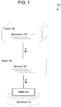
- FIG. 1 is a diagram illustrating a database system architecture in accordance with an example embodiment.
- FIG. 2 is a diagram illustrating a process of GUIDs being generated in accordance with an example embodiment.
- FIGS. 3A-3B are diagrams illustrating a process of transforming a GUID into a reduced identifier in accordance with example embodiment.
- FIG. 4 is a diagram illustrating a process of adding a prefix to a reduced identifier based on purpose in accordance with an example embodiment.
- FIG. 5 is a diagram illustrating a method of transforming a GUID into a reduced identifier in accordance with an example embodiment.
- FIG. 6 is a diagram illustrating a computing system for use in the examples herein in accordance with an example embodiment.
- the example embodiments overcome the drawbacks in the prior art by transforming a global identifier (GUID) into a reduced identifier which is local to the database using a bijective transformation function.
- GUID global identifier
- the resulting reduced identifier is smaller in size but still unique to the system thereby reducing the amount of storage occupied by GUIDs.
- the reduced identifier can replace the GUID and can be used to uniquely identify a database item within the database system.
- an inverse of the bijective function that is used to transform the GUID into the reduced identifier can be used to regenerate the GUID based on the reduced identifier, if necessary.
- GUIDs can be replaced/removed from the system.
- the GUIDs are removed not only on the database table but also from dictionary tables. Rather, the only remaining identifier is the reduced identifier. If necessary, the reduced identifier can be used to recalculate the GUID based on an inverse transform function, but this situation will be rare.
- GUIDs are typically between 16-32 bytes (128 to 256 bits) depending on the data type. However, much of the data within a GUID is not needed and is generated based on the mechanism used to create the GUID which can vary. Examples of GUID creation methods include random numbers, timestamp-based, content-based, and the like.
- the example embodiments use a bijective transformation function to reduce the GUID from a numerical value of 16 or 32 bytes to a numerical value having 3-4 bytes. Furthermore, instead of keeping a mapping, the database only has to store the bijective transformation function that is used to convert the GUID to a reduced unique identifier.
- a numerical value of a GUID may be normalized to reduce a numerical gap between a numerical value of a previous GUID generated by the system.
- the normalized GUID may be converted using a function that essentially removes or subtracts a number of digits from the GUID while retaining enough unique digits such that a unique reduced identifier is possible within the database system.
- the normalization process can tightly pack numerical values together in sequence (e.g., incremental, etc.) By tightly packing the numerical values, the amount of GUIDS that can be converted using the function may be increased.
- FIG. 1 illustrates a system architecture of a database 100 in accordance with an example embodiment. It should be appreciated that the embodiments are not limited to architecture 100 or to a database architecture, however, FIG. 1 is shown for purposes of example.
- the architecture 100 includes a data store 110 , a database management system (DBMS) 120 , a server 130 , services 135 , clients 140 and applications 145 .
- DBMS database management system
- services 135 executing within server 130 receive requests from applications 145 executing on clients 140 and provides results to applications 145 based on data stored within data store 110 .
- server 130 may execute and provide services 135 to applications 145 .
- Services 135 may comprise server-side executable program code (e.g., compiled code, scripts, etc.) which provide functionality to applications 145 by providing user interfaces to clients 140 , receiving requests from applications 145 (e.g., drag-and-drop operations), retrieving data from data store 110 based on the requests, processing the data received from data store 110 , and providing the processed data to applications 145 .
- server-side executable program code e.g., compiled code, scripts, etc.
- a client 140 may execute an application 145 to perform visual analysis of analytical data output to a user interface on a display of the client 140 which allows the user to view analytical information such as charts, graphs, tables, and the like, based on the underlying data stored in the data store 110 .
- the application 145 may pass analytic information based on the input to one of services 135 .
- a structured query language (SQL) script may be generated based on the request and forwarded to DBMS 120 .
- DBMS 120 may execute the SQL script to return a result set based on data of data store 110 , and the application 145 creates a report/visualization based on the result set.
- SQL structured query language
- analytic data may be input by the user and provided directly from the application 145 to the DBMS 120 or the data store 110 .
- an application 145 may include the logical components to perform the data merge and conflict resolution steps/processes described herein.
- the services 135 executing on server 130 may communicate with DBMS 120 using database management interfaces such as, but not limited to, Open Database Connectivity (ODBC) and Java Database Connectivity (JDBC) interfaces. These types of services 135 may use SQL to manage and query data stored in data store 110 .
- the DBMS 125 serves requests to query, retrieve, create, modify (update), and/or delete data from database files stored in data store 110 , and also performs administrative and management functions. Such functions may include snapshot and backup management, indexing, optimization, garbage collection, and/or any other database functions that are or become known.
- Server 130 may be separated from or closely integrated with DBMS 120 .
- a closely-integrated server 130 may enable execution of services 135 completely on the database platform, without the need for an additional server.
- server 130 may provide a comprehensive set of embedded services which provide end-to-end support for Web-based applications.
- the services 135 may include a lightweight web server, configurable support for Open Data Protocol, server-side JavaScript execution and access to SQL and SQLScript.
- Server 130 may provide application services (e.g., via functional libraries) using services 135 that manage and query the database files stored in the data store 110 .
- the application services can be used to expose the database data model, with its tables, views and database procedures, to clients 140 .
- server 130 may host system services such as a search service, and the like.
- Data store 110 may be any query-responsive data source or sources that are or become known, including but not limited to a SQL relational database management system.
- Data store 110 may include or otherwise be associated with a relational database, a multi-dimensional database, an Extensible Markup Language (XML) document, or any other data storage system that stores structured and/or unstructured data.
- the data of data store 110 may be distributed among several relational databases, dimensional databases, and/or other data sources. Embodiments are not limited to any number or types of data sources.
- the data of data store 110 may include files having one or more of conventional tabular data, row-based data, column-based data, object-based data, and the like.
- Data store 110 may support multi-tenancy to separately support multiple unrelated clients by providing multiple logical database systems which are programmatically isolated from one another. Furthermore, data store 110 may support multiple users that are associated with the same client and that share access to common database files stored in the data store 110 .
- data items may be stored, modified, deleted, and the like, within the data store 110 .
- data items may be created, modified, or deleted based on instructions from any of the applications 145 , the services 135 , and the like.
- Each data item may be assigned a globally unique identifier (GUID) by an operating system, or other program of the database 100 .
- GUID is used to uniquely identify that data item from among all other data items stored within the database 100 .
- GUIDs may be created in multiple ways including, but not limited to, random, time-based, hardware-based, content-based, a combination thereof, and the like. Examples of conventions for creating GUIDs are described in RFC 4122 .
- a random-number generator may be used to create a GUID (e.g., a 128-bit number, etc.)
- a time-based GUID may be created based on a current time detected from a system clock.
- Hardware-based GUIDs may be generated based on a MAC address of a network card, etc.
- content-based GUIDs may be created based on a hash of the file contents.
- the architecture 100 may include metadata defining objects which are mapped to logical entities of data store 110 .
- the metadata may be stored in data store 110 and/or a separate repository (not shown).
- the metadata may include information regarding dimension names (e.g., country, year, product, etc.), dimension hierarchies (e.g., country, state, city, etc.), measure names (e.g., profit, units, sales, etc.) and any other suitable metadata.
- the metadata includes information associating users, queries, query patterns and visualizations. The information may be collected during operation of system and may be used to determine a visualization to present in response to a received query, and based on the query and the user from whom the query was received.
- Each of clients 140 may include one or more devices executing program code of an application 145 for presenting user interfaces to allow interaction with application server 130 .
- the user interfaces of applications 145 may comprise user interfaces suited for reporting, data analysis, and/or any other functions based on the data of data store 110 .
- Presentation of a user interface may include any degree or type of rendering, depending on the type of user interface code generated by server 130 .
- a client 140 may execute a Web Browser to request and receive a Web page (e.g., in HTML format) from application server 130 via HTTP, HTTPS, and/or Web Socket, and may render and present the Web page according to known protocols.
- One or more of clients 140 may also or alternatively present user interfaces by executing a standalone executable file (e.g., an .exe file) or code (e.g., a JAVA applet) within a virtual machine.
- Clients 140 may execute applications 145 which perform merge operations of underlying data files stored in data store 120 .
- clients 140 may execute the conflict resolution methods and processes described herein to resolve data conflicts between different versions of a data file stored in the data store 110 .
- a user interface may be used to display underlying data records, and the like.
- FIG. 2 illustrates a process 200 of GUIDs being generated by a database 210 in accordance with an example embodiment.
- the database 210 e.g., an operating system, a program, etc.
- the database items 212 can include storage records that are generated when data is inserted, deleted, modified, etc.
- the database entries may be stored in database tables.
- the process 200 generates five database entries 212 over time causing the database 210 to generate five GUIDs 220 which may be stored in a table along with other data of the database entries 212 (which is not shown in this example).
- GUIDs are unique across every table, every database, every server, on a global basis. While it cannot be completely ensured that a GUID is not going to be duplicated, the chances are so unlikely that it is considered negligible.
- GUIDs allow for easy merging of records from different database systems that rely on GUIDs as unique identifiers.
- GUIDs allow for easy distribution of databases across multiple servers. The database can generate GUIDs anywhere, instead of having to roundtrip to the database. Furthermore, most replication scenarios require GUID columns anyway.
- GUIDs are 4 times larger than a traditional 4-byte index value. This can cause serious performance and storage issues if not used carefully. GUIDs are cumbers some to debug, hard to manipulate, can cause the index to bloat, can require fragmentation, and can increase the cost of table maintenance. The generated GUIDs should be partially sequential for best performance and to enable use of clustered indexes. This can create further issues.
- FIGS. 3A-3B illustrate a process of transforming a GUID into a reduced identifier in accordance with example embodiment.
- the end-to-end process may include a normalization process in 300 A of FIG. 3A , and a transformation process in 300 B of FIG. 3B .
- the normalization process is not performed.
- the normalization process may not be needed because a database may automatically generate normalized GUIDs.
- the normalization process 300 A is described herein.
- a bijective function f can be used to transform a GUID into a locally unique identifier (referred to herein as a reduced identifier).
- the inverse function f 1 may be used to transform the reduced identifier back to its original value (i.e., the original GUID).
- the original GUID is not stored any longer but is replaced by the reduced identifier.
- the original GUID is not needed in the database nor in a dictionary table. Rather, only the identifiers and the function f (e.g., an identifier of the function) needs to be stored. Since the function is fixed, the original GUID could be retrieved at any time.
- GUIDs are generated by a simple algorithm, for example, based on system attributes, application/software components, timestamps, randomly, or the like. Thus, a GUID range could be estimated for a certain purpose. GUIDs that are provided for a certain purpose and are usually generated one by one (and are commonly sorted ascending). In some cases, the generation algorithm already represents the inverse function.
- a plurality of GUIDs 312 are created and correspond to a plurality of timestamps 302 , respectively. Initially, the GUIDs are sorted ascending, corresponding to the timestamp. However, as is shown in FIG. 3A , the GUIDs 312 are sorted ascending, but they are not directly following each other. In other words, significant numerical gaps exist between the GUIDs. This could be caused by any number of factors. For example, the GUID may be randomly generated and therefore the gaps are essential. As another example, the GUIDs may be based on timestamps, content, etc., and therefore the gaps are inherent. In the process 300 A the GUIDs 312 are normalized into normalized GUIDs 322 . In this case, the normalization won't affect the uniqueness of the GUID. It just ensures, that the reduced identifier could be derived more easily.
- the normalization function considers only the actual GUIDs, which are present in the system.
- the normalization ensures, that the GUIDs are directly following each other and are tightly packed together thereby reducing numerical gaps.
- the normalization process might be performed by a central service.
- the source code as well as the data flow might be analysed here, to identify columns which belong together. (These columns should be normalized the same way.)
- JOIN conditions might be analysed here.
- an executable program might encapsulate the inverse function which may be used to retrieve the GUID for a given reduced ID.
- the normalized GUIDs 322 are transformed into reduced identifiers 332 using a bijective transformation function 340 which receives the normalized GUID as an input.
- the bijective transformation function 340 includes an offset (FA163ED168331EE88BB66709A33CE000) which is subtracted from each GUID to generate the reduced identifier.
- the system may truncate the remaining digits of the reduced identifier, for example, such that only 10 digits (3 bytes) are used instead of 128 or 256 bits (e.g., 16-byte hexadecimal value, etc.).
- the reduced identifiers 332 may be used to uniquely identify the respective database entries corresponding thereto within the database system, rather than the GUIDs 312 .
- GUIDs 312 instead of storing a 16 byte hexadecimal value GUID, a 3 byte value or a 4 byte value reduced identifier can be stored.
- the bijective transformation function 340 may be stored once and identified by the database and used to regenerate or otherwise recover any GUID.
- an inverse function 342 of the bijective transformation function 340 may be used to recover any GUID that has been transformed into a reduced identifier.
- the inverse function 342 may receive the reduced identifier as an input and recreate the normalized GUID.
- a dictionary table for mapping GUIDs to keys
- the storage savings are significant (e.g., 50% or more) than in comparison to the dictionary compression technique.
- FIG. 4 illustrates a process 400 of adding a prefix to a reduced identifier based on purpose in accordance with an example embodiment.
- data entries may be associated with different purposes.
- a purpose may be related to an application, a tenant/client, a table, a column, or the like, of the database.
- GUIDs 401 are generated for two different purposes A and B.
- the reduced four-byte identifier 402 is represented by a ten-digit integer. Overlapping intervals produce duplicate entries such as shown in reduced identifiers 411 and 412 .
- the system herein can assign a prefix 404 to each reduced identifier and concatenate the prefix 404 to the ten-digit identifier 402 to generate the final reduced identifier.
- the prefix may be assigned based on the purpose from among different prefixes associated with different purposes.
- the prefix only increases the reduced the length of the reduced identifier by 7 bits (2-3 bytes) in this example. Therefore, the overall length is increased to seven bytes, which is still quite less than 16/32 bytes.
- the purpose A is assigned a prefix of “0001247” while the purpose B is assigned a prefix of “0035942.” If the actual GUID is needed, the original value may be recalculated again.
- a simple executable program or a subroutine might be used that stores the prefixes.
- the purpose of a GUID is just for identification. In some cases, a central repository is consumed, containing the function identifiers and the functions themselves. If a new purpose or a new GUID range with a new function is required, the repository may be updated.
- the functions could just consist of a zero-degree polynomial, which results in just an offset. This happens automatically, if the GUID column is normalized. Here it is sufficient just to store the function identifier and a starting value for the GUID range. Because the length of the reduced identifier is significantly shorter than the original GUID, adjustments of the consuming source code might be required (e.g., changes or data declarations in development objects). These adjustments could be derived and performed automatically by an executable program.
- ranges of GUIDs may be replaced with reduced identifiers that are locally unique.
- the reduced identifiers may be generated based on a bijective transformation function that enables the GUID to be recovered if needed.
- different GUID ranges may be replaced with different ranges of reduced identifiers and different bijective transformation functions.
- the data may be associated with a single purpose or it may be associated with multiple purposes.
- the reduced identifier can include a prefix which is concatenated to the initially determined value to further distinguish the reduced identifier based on purpose.
- FIG. 5 illustrates a method 500 of transforming a GUID into a reduced identifier in accordance with an example embodiment.
- the method 500 may be performed by a database node, a cloud platform, a server, a computing system (user device), or the like.
- the method may include receiving a database entry which includes a global unique identifier (GUID) which uniquely identifies the database entry.
- GUID global unique identifier
- the GUID may be created by an operating system or other program.
- the GUID may be created randomly and/or based on other factors such as a timestamp, a content of the database entry, or the like.
- the method may include identifying a transformation function associated with the database entry.
- the transformation function may be a bijective transformation function that is stored within the database.
- the bijective transformation function may convert the GUID into a reduced identifier while an inverse of the bijective transfer function may be configured to regenerate the GUID from the reduced identifier.
- the bijective transfer function may include an offset which is subtracted the GUID to create a smaller numerical value. The offset may be large enough such that most of the values of the GUID become null or zero thereby leaving only a few bit values (e.g., 10, etc.).
- the method may include transforming the GUID into a reduced identifier based on the transformation function, wherein the reduced identifier comprises a reduced size with respect to a size of the GUID, and in 540 , storing the database entry based on the reduced identifier.
- the method may further include normalizing the GUID prior to the transforming to generate a normalized GUID with respect to previous GUIDs among a sequence of GUIDs created by the database.
- the normalization may reduce a numerical gap between GUID values. This can make the transformation function easier to perform.
- the GUID may be automatically normalized to begin with. In other words, the database may initially generate a GUID that has a normalized value.
- the method may further include determining the reduced identifier based on an increment of a previously assigned reduced identifier
- the identifying of the transformation function may also include identifying a purpose associated with the database entry from among a plurality of purposes, and concatenating a prefix to the reduced identifier based on the identified purpose.
- the plurality of purposes may correspond to a plurality of respective columns of data within a database table.
- the prefix may add an additional few bits to the reduced identifier but may prevent duplicate reduced identifiers.
- FIG. 6 illustrates a computing system 600 that may be used in any of the methods and processes described herein, in accordance with an example embodiment.
- the computing system 600 may be a database node, a server, a cloud platform, or the like.
- the computing system 600 may be distributed across multiple devices.
- the computing system 600 includes a network interface 610 , a processor 620 , an output 630 , and a storage device 640 such as an in-memory storage, and the like.
- the computing system 600 may also include or be electronically connected to other components such as a display, an input unit(s), a receiver, a transmitter, a persistent disk, and the like.
- the processor 620 may control the other components of the computing system 600 .
- the network interface 610 may transmit and receive data over a network such as the Internet, a private network, a public network, an enterprise network, and the like.
- the network interface 610 may be a wireless interface, a wired interface, or a combination thereof.
- the processor 620 may include one or more processing devices each including one or more processing cores. In some examples, the processor 620 is a multicore processor or a plurality of multicore processors. Also, the processor 620 may be fixed or it may be reconfigurable.
- the output 630 may output data to an embedded display of the computing system 600 , an externally connected display, a display connected to the cloud, another device, and the like.
- the output 630 may include a port, an interface, a cable, a wire, a board, and/or the like, with input/output capabilities.
- the network interface 610 , the output 630 , or a combination thereof, may interact with applications executing on other devices.
- the storage device 640 is not limited to a particular storage device and may include any known memory device such as RAM, ROM, hard disk, and the like, and may or may not be included within a database system, a cloud environment, a web server, or the like.
- the storage 640 may store software modules or other instructions which can be executed by the processor 620 to perform the method shown in FIG. 5 .
- the storage 640 may include a data store having a plurality of tables, partitions and sub-partitions.
- the storage 640 may be used to store database records, items, entries, and the like.
- the processor 620 may receive a database entry that includes a global unique identifier (GUID) which uniquely identifies the database entry.
- GUID global unique identifier
- the processor 620 may identify a transformation function associated with the database entry which is stored in the database, and transform the GUID into a reduced identifier based on the transformation function.
- the reduced identifier may have a reduced size with respect to a size of the GUID.
- the reduced identifier may be 3 bytes while the GUID may be 16 bytes, 32 bytes, etc.
- the processor 620 may replace the GUID with the reduced identifier in the database and store the database entry within the storage 640 such that the database entry is identified using the reduced identifier.
- the reduced identifier may include a local identifier that is unique within the database system.
- the processor 620 may normalize the GUID prior to the transforming the GUID into the reduced identifier to generate a normalized GUID with respect to previous GUIDs among a sequence of GUIDs created by the database.
- the transformation function may include an offset which the processor 620 subtracts from the GUID to generate the reduced identifier.
- the transformation function may include a bijective transformation function in which an inverse thereof is configured to regenerate the GUID from the reduced identifier.
- the GUID of the database entry may be created based on a timestamp at which the database entry is created by the database.
- the processor 620 may identify a purpose associated with the database entry from among a plurality of purposes, and concatenate a prefix to the reduced identifier based on the identified purpose.
- the plurality of purposes may correspond to a plurality of respective columns of data within a database table.
- the processor 620 may determine the reduced identifier based on an increment of a previously assigned reduced identifier. As a non-limiting example, if a previous reduced identifier is “002000104,” the next reduced identifier that is assigned may be “002000105”. Each reduced identifier in sequence may be incremented by a certain numerical amount (e.g., 1, 2, etc.)
- the above-described examples of the disclosure may be implemented using computer programming or engineering techniques including computer software, firmware, hardware or any combination or subset thereof. Any such resulting program, having computer-readable code, may be embodied or provided within one or more non-transitory computer-readable media, thereby making a computer program product, i.e., an article of manufacture, according to the discussed examples of the disclosure.
- the non-transitory computer-readable media may be, but is not limited to, a fixed drive, diskette, optical disk, magnetic tape, flash memory, external drive, semiconductor memory such as read-only memory (ROM), random-access memory (RAM), and/or any other non-transitory transmitting and/or receiving medium such as the Internet, cloud storage, the Internet of Things (IoT), or other communication network or link.
- the article of manufacture containing the computer code may be made and/or used by executing the code directly from one medium, by copying the code from one medium to another medium, or by transmitting the code over a network.
- the computer programs may include machine instructions for a programmable processor, and may be implemented in a high-level procedural and/or object-oriented programming language, and/or in assembly/machine language.
- the terms “machine-readable medium” and “computer-readable medium” refer to any computer program product, apparatus, cloud storage, internet of things, and/or device (e.g., magnetic discs, optical disks, memory, programmable logic devices (PLDs)) used to provide machine instructions and/or data to a programmable processor, including a machine-readable medium that receives machine instructions as a machine-readable signal.
- PLDs programmable logic devices
- the term “machine-readable signal” refers to any signal that may be used to provide machine instructions and/or any other kind of data to a programmable processor.
Abstract
Description
Claims (21)
Priority Applications (1)
| Application Number | Priority Date | Filing Date | Title |
|---|---|---|---|
| US16/145,924 US11086839B2 (en) | 2018-09-28 | 2018-09-28 | Bijective transformation for compression of GUID |
Applications Claiming Priority (1)
| Application Number | Priority Date | Filing Date | Title |
|---|---|---|---|
| US16/145,924 US11086839B2 (en) | 2018-09-28 | 2018-09-28 | Bijective transformation for compression of GUID |
Publications (2)
| Publication Number | Publication Date |
|---|---|
| US20200104389A1 US20200104389A1 (en) | 2020-04-02 |
| US11086839B2 true US11086839B2 (en) | 2021-08-10 |
Family
ID=69946853
Family Applications (1)
| Application Number | Title | Priority Date | Filing Date |
|---|---|---|---|
| US16/145,924 Active 2039-04-13 US11086839B2 (en) | 2018-09-28 | 2018-09-28 | Bijective transformation for compression of GUID |
Country Status (1)
| Country | Link |
|---|---|
| US (1) | US11086839B2 (en) |
Families Citing this family (1)
| Publication number | Priority date | Publication date | Assignee | Title |
|---|---|---|---|---|
| US11716396B1 (en) * | 2021-08-27 | 2023-08-01 | Oracle International Corporation | System and method for providing unique identifiers for use with enterprise application environments |
Citations (9)
| Publication number | Priority date | Publication date | Assignee | Title |
|---|---|---|---|---|
| US20040215981A1 (en) * | 2003-04-22 | 2004-10-28 | Ricciardi Thomas N. | Method, system and computer product for securing patient identity |
| US20060129540A1 (en) * | 2004-12-15 | 2006-06-15 | Hillis W D | Data store with lock-free stateless paging capability |
| US20070005632A1 (en) * | 2005-06-30 | 2007-01-04 | Microsoft Corporation | Method for efficient maintenance of XML indexes |
| US20080301197A1 (en) * | 2002-05-02 | 2008-12-04 | Palmsource, Inc. | Generating coherent global identifiers for efficient data identification |
| US20090154704A1 (en) * | 2007-12-14 | 2009-06-18 | Farrugia Augustin J | Method and apparatus for securing content using encryption with embedded key in content |
| US20160021064A1 (en) * | 2014-07-15 | 2016-01-21 | Hendrik Lock | System and method to secure sensitive content in a uri |
| US20180219964A1 (en) * | 2017-01-30 | 2018-08-02 | Dell Products, L.P. | Method and system to convert globally unique identifiers to electronic data interchange document identifiers |
| US20180288049A1 (en) * | 2017-03-28 | 2018-10-04 | Amazon Technologies, Inc. | Data access interface for clustered devices |
| US10698825B1 (en) * | 2019-03-12 | 2020-06-30 | Arm Limited | Inter-chip communication in a multi-chip system |
-
2018
- 2018-09-28 US US16/145,924 patent/US11086839B2/en active Active
Patent Citations (9)
| Publication number | Priority date | Publication date | Assignee | Title |
|---|---|---|---|---|
| US20080301197A1 (en) * | 2002-05-02 | 2008-12-04 | Palmsource, Inc. | Generating coherent global identifiers for efficient data identification |
| US20040215981A1 (en) * | 2003-04-22 | 2004-10-28 | Ricciardi Thomas N. | Method, system and computer product for securing patient identity |
| US20060129540A1 (en) * | 2004-12-15 | 2006-06-15 | Hillis W D | Data store with lock-free stateless paging capability |
| US20070005632A1 (en) * | 2005-06-30 | 2007-01-04 | Microsoft Corporation | Method for efficient maintenance of XML indexes |
| US20090154704A1 (en) * | 2007-12-14 | 2009-06-18 | Farrugia Augustin J | Method and apparatus for securing content using encryption with embedded key in content |
| US20160021064A1 (en) * | 2014-07-15 | 2016-01-21 | Hendrik Lock | System and method to secure sensitive content in a uri |
| US20180219964A1 (en) * | 2017-01-30 | 2018-08-02 | Dell Products, L.P. | Method and system to convert globally unique identifiers to electronic data interchange document identifiers |
| US20180288049A1 (en) * | 2017-03-28 | 2018-10-04 | Amazon Technologies, Inc. | Data access interface for clustered devices |
| US10698825B1 (en) * | 2019-03-12 | 2020-06-30 | Arm Limited | Inter-chip communication in a multi-chip system |
Also Published As
| Publication number | Publication date |
|---|---|
| US20200104389A1 (en) | 2020-04-02 |
Similar Documents
| Publication | Publication Date | Title |
|---|---|---|
| US11475034B2 (en) | Schemaless to relational representation conversion | |
| US9805079B2 (en) | Executing constant time relational queries against structured and semi-structured data | |
| CN111164585B (en) | Performing in-memory rank analysis queries on externally resident data | |
| US10628449B2 (en) | Method and apparatus for processing database data in distributed database system | |
| US10296611B2 (en) | Optimized rollover processes to accommodate a change in value identifier bit size and related system reload processes | |
| US9817858B2 (en) | Generating hash values | |
| US20140214897A1 (en) | SYSTEMS AND METHODS FOR ACCESSING A NoSQL DATABASE USING BUSINESS INTELLIGENCE TOOLS | |
| US20120239612A1 (en) | User defined functions for data loading | |
| US8880463B2 (en) | Standardized framework for reporting archived legacy system data | |
| CN107729399B (en) | Data processing method and device | |
| US20090287986A1 (en) | Managing storage of individually accessible data units | |
| US11074261B1 (en) | Format independent processing for distributed data | |
| US20120131022A1 (en) | Methods and systems for merging data sets | |
| US10296499B2 (en) | Dynamic database mapping | |
| US11461333B2 (en) | Vertical union of feature-based datasets | |
| US11468031B1 (en) | Methods and apparatus for efficiently scaling real-time indexing | |
| US9053207B2 (en) | Adaptive query expression builder for an on-demand data service | |
| US11567969B2 (en) | Unbalanced partitioning of database for application data | |
| CN112912870A (en) | Tenant identifier conversion | |
| US11086839B2 (en) | Bijective transformation for compression of GUID | |
| US11657051B2 (en) | Methods and apparatus for efficiently scaling result caching | |
| US8005844B2 (en) | On-line organization of data sets | |
| US20200311067A1 (en) | Database partition pruning using dependency graph | |
| US20200311076A1 (en) | Database partition pruning using dependency graph | |
| US10325106B1 (en) | Apparatus and method for operating a triple store database with document based triple access security |
Legal Events
| Date | Code | Title | Description |
|---|---|---|---|
| AS | Assignment |
Owner name: SAP SE, GERMANY Free format text: ASSIGNMENT OF ASSIGNORS INTEREST;ASSIGNOR:MIETKE, SEBASTIAN;REEL/FRAME:047007/0286 Effective date: 20180928 |
|
| FEPP | Fee payment procedure |
Free format text: ENTITY STATUS SET TO UNDISCOUNTED (ORIGINAL EVENT CODE: BIG.); ENTITY STATUS OF PATENT OWNER: LARGE ENTITY |
|
| STPP | Information on status: patent application and granting procedure in general |
Free format text: NON FINAL ACTION MAILED |
|
| STPP | Information on status: patent application and granting procedure in general |
Free format text: RESPONSE AFTER FINAL ACTION FORWARDED TO EXAMINER |
|
| STPP | Information on status: patent application and granting procedure in general |
Free format text: ADVISORY ACTION MAILED |
|
| STPP | Information on status: patent application and granting procedure in general |
Free format text: DOCKETED NEW CASE - READY FOR EXAMINATION |
|
| STPP | Information on status: patent application and granting procedure in general |
Free format text: NOTICE OF ALLOWANCE MAILED -- APPLICATION RECEIVED IN OFFICE OF PUBLICATIONS |
|
| STPP | Information on status: patent application and granting procedure in general |
Free format text: PUBLICATIONS -- ISSUE FEE PAYMENT RECEIVED |
|
| STPP | Information on status: patent application and granting procedure in general |
Free format text: PUBLICATIONS -- ISSUE FEE PAYMENT VERIFIED |
|
| STCF | Information on status: patent grant |
Free format text: PATENTED CASE |