US1108564A - Spring vehicle-wheel. - Google Patents
Spring vehicle-wheel. Download PDFInfo
- Publication number
- US1108564A US1108564A US82344014A US1914823440A US1108564A US 1108564 A US1108564 A US 1108564A US 82344014 A US82344014 A US 82344014A US 1914823440 A US1914823440 A US 1914823440A US 1108564 A US1108564 A US 1108564A
- Authority
- US
- United States
- Prior art keywords
- spring
- wheel
- frame
- band
- stem
- Prior art date
- Legal status (The legal status is an assumption and is not a legal conclusion. Google has not performed a legal analysis and makes no representation as to the accuracy of the status listed.)
- Expired - Lifetime
Links
- 238000010276 construction Methods 0.000 description 2
- 230000006872 improvement Effects 0.000 description 2
- 239000000463 material Substances 0.000 description 2
- 239000002184 metal Substances 0.000 description 1
- 229920000136 polysorbate Polymers 0.000 description 1
- 239000007787 solid Substances 0.000 description 1
- 239000004575 stone Substances 0.000 description 1
Images
Classifications
-
- B—PERFORMING OPERATIONS; TRANSPORTING
- B60—VEHICLES IN GENERAL
- B60B—VEHICLE WHEELS; CASTORS; AXLES FOR WHEELS OR CASTORS; INCREASING WHEEL ADHESION
- B60B9/00—Wheels of high resiliency, e.g. with conical interacting pressure-surfaces
- B60B9/02—Wheels of high resiliency, e.g. with conical interacting pressure-surfaces using springs resiliently mounted bicycle rims
- B60B9/06—Wheels of high resiliency, e.g. with conical interacting pressure-surfaces using springs resiliently mounted bicycle rims in helical form
Definitions
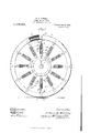
- My invention relates particularly to an improved construction of the springs used for connecting the wheel-center with the rim where the latter is an annular' spring-band.
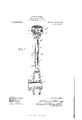
- Figure l shows a wheel embodying my impro-vement by a view in side elevation, partly broken; and Fig. 2 is an enlarged section on line. 2, Fig. l.
- the wheel-center shown is a hub 3 having a disk l formed integra-l with it and a companion-disk 5 fitting an offset near one end of the hub.
- the band-spring G shown to be formed of two concentric bands embedded in a solid tire 7 of rubber or other suitable material, carries at uniform intervals clips 8, each of the preferred construction illustrated in Fig. 2, comprising a cross-plate 8f* and a socket-head 8b embracing the bandspring between them and rigidly fastened together by bolts crossing the opposite edges of the annulus and about which and the crossplate and socket-heads the material. of the tire 7 is shown to be molded.
- the center and band-spring are connected at each clip by a spoke-like spring-device 9.
- This device comprises a headed stem 9 pivotally pinned through the head in a sockethead 8b and provided between its ends with a threaded section 9b, the stem extending through the outer-end and side members of an open rectangular metal frame 9C into a socket 9d in its lower member, which is piv ⁇ otally pinned between the disks le and 5; on the ste1n-thread is a nut l0, between which and the inner end-member of the frame is confined a spiral spring ll, and a similar spring l2 is confined in the frame be tween its outer-end member and a nut l0 on the stem-thread.
- annular springband having a degree of rigidity that will cause it to resist iiexure under a given load.
- the springs 12 of the spokelike devices 9 are put by their nuts l0 under a tension sufficient to support that load and exert a uniform centripetal tension on the annular spring to maintain its circular shape under normal conditions.
- the 'wheel is subjected to strain beyond the aforesaid given load, as in encountering a stone or other obstruction in its path, the impact will flex the band G at the point where it encounters the obstruction and overcome the resistance of the springs 12 in the lower part of the wheel to permit resilient action of the annular band.
- the springs 11 are put by the nuts l0 under a predetermined tension greater than that of the springs 12, and serve the purpose of causing the wheel to respond resiliently in ease of an overload of given amount, such as results from the wheel entering a more or less deep rut.
- the overload is then taken by the springs l1 in compressing under its force in resiliently flexing the annular' spring 6.
- a spring vehicle-wheel having an annular band-spring, a wheel-center, and. springdeviees connecting the band-spring and wheel-center at intervals and each comprising a frame pivotally connected at its inner end with said center, a stem pivotally connected with the band-spring, said stem working lengthwise in the frame and ⁇ having a threaded section, nuts on said threaded section, a springl confined about the stem between ene nut and the outer end of the frame, and a spring confined about the stein between the other nut and the inner end of the frame.
- a spring vehicle-wheel having an annular band-spring, a wheel-center, and. spring-devices connecting the band-spring and wheehcenter at intervals and each comprising' a frame having a socket in its inner end at which it pivotally connected with said center, a stein piif'otally connected with the band-spring, said stein extending through the frame into said socket and having a threaded section, nuts on said threaded section, a spring confined about the stem between one nut and the outer end ⁇ of the frame, and a spring confined about the stem between the other nut and the inner end of the frame.
Landscapes
- Engineering & Computer Science (AREA)
- Mechanical Engineering (AREA)
- Springs (AREA)
Description
W. E. FAHRNBY.
SPRING VEHICLE WHEEL.
APPLIOATIUN FILED Mmm. 1914.
1,108,564, Patented Aug.25,1914.
2 SHEETS-SHEET l.
7eme Zzf zzmm K55/Engg THE AORRIS PETERS C0.4 PHnrU-LlTHO.. WASHINGTUN, u, c.
W. H. FAHRNEY.
SPRING VEHICLE WHEEL.
APPLICATION FILED Mmm, 1914.
1 l 08, 5 64 Patented Aug. 25, 191% Z SHEETS-SHEET 2.
www@
WILLIAM H. FAHRNEY, OF CHICAGO, ILLINOIS.
SPRING' VEHICLE-WHEEL.
Specicatien of Letters Patent.
Application filed March 9, 1914. Serial No. 823,440.
To ctZZ whom 'it may concern:
Be it known that I, WILLIAM H. FAHR- NEY, a citizen of the United States, residing at Chicago, in the county of Cook and State of illinois, have invented a new and useful improvement in Spring Vehicle-'Vheels, of which the following is a specification.
My invention relates particularly to an improved construction of the springs used for connecting the wheel-center with the rim where the latter is an annular' spring-band.
`ln the accompanying' drawing, Figure l shows a wheel embodying my impro-vement by a view in side elevation, partly broken; and Fig. 2 is an enlarged section on line. 2, Fig. l.
The wheel-center shown is a hub 3 having a disk l formed integra-l with it and a companion-disk 5 fitting an offset near one end of the hub. The band-spring G, shown to be formed of two concentric bands embedded in a solid tire 7 of rubber or other suitable material, carries at uniform intervals clips 8, each of the preferred construction illustrated in Fig. 2, comprising a cross-plate 8f* and a socket-head 8b embracing the bandspring between them and rigidly fastened together by bolts crossing the opposite edges of the annulus and about which and the crossplate and socket-heads the material. of the tire 7 is shown to be molded. The center and band-spring are connected at each clip by a spoke-like spring-device 9. This device comprises a headed stem 9 pivotally pinned through the head in a sockethead 8b and provided between its ends with a threaded section 9b, the stem extending through the outer-end and side members of an open rectangular metal frame 9C into a socket 9d in its lower member, which is piv` otally pinned between the disks le and 5; on the ste1n-thread is a nut l0, between which and the inner end-member of the frame is confined a spiral spring ll, and a similar spring l2 is confined in the frame be tween its outer-end member and a nut l0 on the stem-thread.
To construct the wheel, an annular springband is used having a degree of rigidity that will cause it to resist iiexure under a given load. The springs 12 of the spokelike devices 9 are put by their nuts l0 under a tension sufficient to support that load and exert a uniform centripetal tension on the annular spring to maintain its circular shape under normal conditions. When, however, the 'wheel is subjected to strain beyond the aforesaid given load, as in encountering a stone or other obstruction in its path, the impact will flex the band G at the point where it encounters the obstruction and overcome the resistance of the springs 12 in the lower part of the wheel to permit resilient action of the annular band.
The springs 11 are put by the nuts l0 under a predetermined tension greater than that of the springs 12, and serve the purpose of causing the wheel to respond resiliently in ease of an overload of given amount, such as results from the wheel entering a more or less deep rut. The overload is then taken by the springs l1 in compressing under its force in resiliently flexing the annular' spring 6.
lVhat I claim as new and desire to secure by Letters Patent is l. A spring vehicle-wheel having an annular band-spring, a wheel-center, and. springdeviees connecting the band-spring and wheel-center at intervals and each comprising a frame pivotally connected at its inner end with said center, a stem pivotally connected with the band-spring, said stem working lengthwise in the frame and` having a threaded section, nuts on said threaded section, a springl confined about the stem between ene nut and the outer end of the frame, and a spring confined about the stein between the other nut and the inner end of the frame.
Q. A spring vehicle-wheel having an annular band-spring, a wheel-center, and. spring-devices connecting the band-spring and wheehcenter at intervals and each comprising' a frame having a socket in its inner end at which it pivotally connected with said center, a stein piif'otally connected with the band-spring, said stein extending through the frame into said socket and having a threaded section, nuts on said threaded section, a spring confined about the stem between one nut and the outer end `of the frame, and a spring confined about the stem between the other nut and the inner end of the frame.
l/VILLIAM H. liiil-IRNEY.
In presence of- D. C. TI-Ionsnn, A. C. FISCHER.
Copies of this patent may be obtained for ve cents each, by addressing the Commissioner of Patents, Washington, D. C."
Patented any. 25, 1914.
Priority Applications (1)
| Application Number | Priority Date | Filing Date | Title |
|---|---|---|---|
| US82344014A US1108564A (en) | 1914-03-09 | 1914-03-09 | Spring vehicle-wheel. |
Applications Claiming Priority (1)
| Application Number | Priority Date | Filing Date | Title |
|---|---|---|---|
| US82344014A US1108564A (en) | 1914-03-09 | 1914-03-09 | Spring vehicle-wheel. |
Publications (1)
| Publication Number | Publication Date |
|---|---|
| US1108564A true US1108564A (en) | 1914-08-25 |
Family
ID=3176756
Family Applications (1)
| Application Number | Title | Priority Date | Filing Date |
|---|---|---|---|
| US82344014A Expired - Lifetime US1108564A (en) | 1914-03-09 | 1914-03-09 | Spring vehicle-wheel. |
Country Status (1)
| Country | Link |
|---|---|
| US (1) | US1108564A (en) |
-
1914
- 1914-03-09 US US82344014A patent/US1108564A/en not_active Expired - Lifetime
Similar Documents
| Publication | Publication Date | Title |
|---|---|---|
| US1108564A (en) | Spring vehicle-wheel. | |
| US1060480A (en) | Resilient wheel. | |
| US919826A (en) | Vehicle-wheel. | |
| US794202A (en) | Spring-wheel. | |
| US854238A (en) | Spring-wheel. | |
| US1166155A (en) | Resilient wheel. | |
| US1036828A (en) | Spring-wheel. | |
| US936708A (en) | Wheel. | |
| US899668A (en) | Spring-wheel. | |
| US1007088A (en) | Vehicle-wheel. | |
| US805647A (en) | Spring-wheel. | |
| US1125864A (en) | Spring-tire. | |
| US1203227A (en) | Spring-wheel. | |
| US10184A (en) | Car-wheel | |
| US1212607A (en) | Spring-wheel. | |
| US1255416A (en) | Spring-wheel. | |
| US1211504A (en) | Wheel structure. | |
| US1200316A (en) | Spring-wheel for vehicles. | |
| US971067A (en) | Spring-wheel. | |
| US1288285A (en) | Wheel. | |
| US1031269A (en) | Spring-wheel. | |
| US1247207A (en) | Detachable tread for wheel-tires. | |
| US1198230A (en) | Spring-wheel. | |
| US963742A (en) | Spring-wheel. | |
| US780154A (en) | Rubber tire. |