US11084226B2 - Securing a second object to a first object - Google Patents
Securing a second object to a first object Download PDFInfo
- Publication number
- US11084226B2 US11084226B2 US16/318,236 US201716318236A US11084226B2 US 11084226 B2 US11084226 B2 US 11084226B2 US 201716318236 A US201716318236 A US 201716318236A US 11084226 B2 US11084226 B2 US 11084226B2
- Authority
- US
- United States
- Prior art keywords
- connector
- low density
- density layer
- layer
- building
- Prior art date
- Legal status (The legal status is an assumption and is not a legal conclusion. Google has not performed a legal analysis and makes no representation as to the accuracy of the status listed.)
- Active, expires
Links
- 238000000034 method Methods 0.000 claims abstract description 97
- 239000000463 material Substances 0.000 claims abstract description 91
- 239000012815 thermoplastic material Substances 0.000 claims abstract description 61
- 238000003825 pressing Methods 0.000 claims abstract description 55
- 238000004873 anchoring Methods 0.000 claims abstract description 52
- 230000008878 coupling Effects 0.000 claims abstract description 23
- 238000010168 coupling process Methods 0.000 claims abstract description 23
- 238000005859 coupling reaction Methods 0.000 claims abstract description 23
- 230000009969 flowable effect Effects 0.000 claims abstract description 20
- 230000001070 adhesive effect Effects 0.000 claims description 45
- 239000000853 adhesive Substances 0.000 claims description 44
- 239000006260 foam Substances 0.000 claims description 14
- 239000011148 porous material Substances 0.000 claims description 5
- 230000000295 complement effect Effects 0.000 claims 1
- 239000010410 layer Substances 0.000 description 182
- 230000008569 process Effects 0.000 description 40
- 238000010276 construction Methods 0.000 description 16
- 229920001169 thermoplastic Polymers 0.000 description 16
- 239000004416 thermosoftening plastic Substances 0.000 description 15
- 238000013459 approach Methods 0.000 description 11
- 238000007373 indentation Methods 0.000 description 11
- 238000003780 insertion Methods 0.000 description 10
- 230000037431 insertion Effects 0.000 description 10
- 238000002844 melting Methods 0.000 description 10
- 230000008018 melting Effects 0.000 description 10
- 239000000835 fiber Substances 0.000 description 9
- 229920003023 plastic Polymers 0.000 description 9
- 239000004033 plastic Substances 0.000 description 9
- 239000003381 stabilizer Substances 0.000 description 9
- 239000002131 composite material Substances 0.000 description 7
- 238000004519 manufacturing process Methods 0.000 description 7
- -1 Polypropylene Polymers 0.000 description 6
- 239000011162 core material Substances 0.000 description 5
- 229910052751 metal Inorganic materials 0.000 description 5
- 239000002184 metal Substances 0.000 description 5
- 230000035515 penetration Effects 0.000 description 5
- 229920000642 polymer Polymers 0.000 description 5
- 230000003014 reinforcing effect Effects 0.000 description 5
- 238000003466 welding Methods 0.000 description 5
- 239000004743 Polypropylene Substances 0.000 description 4
- 239000012792 core layer Substances 0.000 description 4
- 239000000945 filler Substances 0.000 description 4
- 239000003365 glass fiber Substances 0.000 description 4
- 230000009477 glass transition Effects 0.000 description 4
- 238000004080 punching Methods 0.000 description 4
- 230000002787 reinforcement Effects 0.000 description 4
- 239000007787 solid Substances 0.000 description 4
- 229910000831 Steel Inorganic materials 0.000 description 3
- 239000000919 ceramic Substances 0.000 description 3
- 238000005553 drilling Methods 0.000 description 3
- 230000000694 effects Effects 0.000 description 3
- 239000002245 particle Substances 0.000 description 3
- 229920002635 polyurethane Polymers 0.000 description 3
- 239000004814 polyurethane Substances 0.000 description 3
- 238000007711 solidification Methods 0.000 description 3
- 239000010959 steel Substances 0.000 description 3
- 229920000049 Carbon (fiber) Polymers 0.000 description 2
- 229920000784 Nomex Polymers 0.000 description 2
- 239000004698 Polyethylene Substances 0.000 description 2
- 238000000418 atomic force spectrum Methods 0.000 description 2
- 230000008901 benefit Effects 0.000 description 2
- 229910052799 carbon Inorganic materials 0.000 description 2
- 239000004917 carbon fiber Substances 0.000 description 2
- 238000005520 cutting process Methods 0.000 description 2
- 230000002708 enhancing effect Effects 0.000 description 2
- 239000006261 foam material Substances 0.000 description 2
- 238000005187 foaming Methods 0.000 description 2
- 239000007788 liquid Substances 0.000 description 2
- 238000011089 mechanical engineering Methods 0.000 description 2
- 239000000203 mixture Substances 0.000 description 2
- 239000004763 nomex Substances 0.000 description 2
- 229920001643 poly(ether ketone) Polymers 0.000 description 2
- 229920003229 poly(methyl methacrylate) Polymers 0.000 description 2
- 229920001707 polybutylene terephthalate Polymers 0.000 description 2
- 229920000728 polyester Polymers 0.000 description 2
- 229920000573 polyethylene Polymers 0.000 description 2
- 229920000139 polyethylene terephthalate Polymers 0.000 description 2
- 239000004926 polymethyl methacrylate Substances 0.000 description 2
- 229920001155 polypropylene Polymers 0.000 description 2
- 230000000087 stabilizing effect Effects 0.000 description 2
- 229920000638 styrene acrylonitrile Polymers 0.000 description 2
- 229920001187 thermosetting polymer Polymers 0.000 description 2
- 239000002023 wood Substances 0.000 description 2
- OKTJSMMVPCPJKN-UHFFFAOYSA-N Carbon Chemical compound [C] OKTJSMMVPCPJKN-UHFFFAOYSA-N 0.000 description 1
- BVKZGUZCCUSVTD-UHFFFAOYSA-L Carbonate Chemical compound [O-]C([O-])=O BVKZGUZCCUSVTD-UHFFFAOYSA-L 0.000 description 1
- 229920000271 Kevlar® Polymers 0.000 description 1
- 229920000571 Nylon 11 Polymers 0.000 description 1
- 229920000299 Nylon 12 Polymers 0.000 description 1
- 229920002292 Nylon 6 Polymers 0.000 description 1
- 229920002302 Nylon 6,6 Polymers 0.000 description 1
- 229930040373 Paraformaldehyde Natural products 0.000 description 1
- 239000004952 Polyamide Substances 0.000 description 1
- 239000004697 Polyetherimide Substances 0.000 description 1
- 239000004793 Polystyrene Substances 0.000 description 1
- 229910052581 Si3N4 Inorganic materials 0.000 description 1
- 239000004433 Thermoplastic polyurethane Substances 0.000 description 1
- 239000004676 acrylonitrile butadiene styrene Substances 0.000 description 1
- 230000002730 additional effect Effects 0.000 description 1
- 229910052782 aluminium Inorganic materials 0.000 description 1
- XAGFODPZIPBFFR-UHFFFAOYSA-N aluminium Chemical compound [Al] XAGFODPZIPBFFR-UHFFFAOYSA-N 0.000 description 1
- 230000004888 barrier function Effects 0.000 description 1
- 238000005452 bending Methods 0.000 description 1
- 210000000746 body region Anatomy 0.000 description 1
- 238000009435 building construction Methods 0.000 description 1
- 239000004566 building material Substances 0.000 description 1
- 230000008859 change Effects 0.000 description 1
- 230000006835 compression Effects 0.000 description 1
- 238000007906 compression Methods 0.000 description 1
- 229920001577 copolymer Polymers 0.000 description 1
- 238000004132 cross linking Methods 0.000 description 1
- 238000002425 crystallisation Methods 0.000 description 1
- 230000008025 crystallization Effects 0.000 description 1
- 230000007547 defect Effects 0.000 description 1
- 230000000593 degrading effect Effects 0.000 description 1
- 230000001934 delay Effects 0.000 description 1
- KZHJGOXRZJKJNY-UHFFFAOYSA-N dioxosilane;oxo(oxoalumanyloxy)alumane Chemical compound O=[Si]=O.O=[Si]=O.O=[Al]O[Al]=O.O=[Al]O[Al]=O.O=[Al]O[Al]=O KZHJGOXRZJKJNY-UHFFFAOYSA-N 0.000 description 1
- 238000006073 displacement reaction Methods 0.000 description 1
- 230000005489 elastic deformation Effects 0.000 description 1
- 238000001125 extrusion Methods 0.000 description 1
- 239000011094 fiberboard Substances 0.000 description 1
- 239000002657 fibrous material Substances 0.000 description 1
- 239000011888 foil Substances 0.000 description 1
- 239000011521 glass Substances 0.000 description 1
- 230000005484 gravity Effects 0.000 description 1
- 238000010438 heat treatment Methods 0.000 description 1
- 230000010354 integration Effects 0.000 description 1
- 230000009916 joint effect Effects 0.000 description 1
- 239000004761 kevlar Substances 0.000 description 1
- 239000003562 lightweight material Substances 0.000 description 1
- 239000007791 liquid phase Substances 0.000 description 1
- 230000003137 locomotive effect Effects 0.000 description 1
- 230000007774 longterm Effects 0.000 description 1
- 239000004620 low density foam Substances 0.000 description 1
- 230000007246 mechanism Effects 0.000 description 1
- 239000012528 membrane Substances 0.000 description 1
- 239000006262 metallic foam Substances 0.000 description 1
- VNWKTOKETHGBQD-UHFFFAOYSA-N methane Chemical compound C VNWKTOKETHGBQD-UHFFFAOYSA-N 0.000 description 1
- 238000003801 milling Methods 0.000 description 1
- 229910052863 mullite Inorganic materials 0.000 description 1
- 239000005445 natural material Substances 0.000 description 1
- 230000010355 oscillation Effects 0.000 description 1
- 239000000123 paper Substances 0.000 description 1
- 239000012071 phase Substances 0.000 description 1
- 229910052698 phosphorus Inorganic materials 0.000 description 1
- 229920002647 polyamide Polymers 0.000 description 1
- 239000004417 polycarbonate Substances 0.000 description 1
- 229920000515 polycarbonate Polymers 0.000 description 1
- 229920001692 polycarbonate urethane Polymers 0.000 description 1
- 229920001601 polyetherimide Polymers 0.000 description 1
- 239000002861 polymer material Substances 0.000 description 1
- 229920006324 polyoxymethylene Polymers 0.000 description 1
- 229920002223 polystyrene Polymers 0.000 description 1
- 239000004800 polyvinyl chloride Substances 0.000 description 1
- 229920000915 polyvinyl chloride Polymers 0.000 description 1
- 239000000843 powder Substances 0.000 description 1
- SCUZVMOVTVSBLE-UHFFFAOYSA-N prop-2-enenitrile;styrene Chemical compound C=CC#N.C=CC1=CC=CC=C1 SCUZVMOVTVSBLE-UHFFFAOYSA-N 0.000 description 1
- 230000005855 radiation Effects 0.000 description 1
- 239000012783 reinforcing fiber Substances 0.000 description 1
- 230000000630 rising effect Effects 0.000 description 1
- 229910052710 silicon Inorganic materials 0.000 description 1
- HBMJWWWQQXIZIP-UHFFFAOYSA-N silicon carbide Chemical compound [Si+]#[C-] HBMJWWWQQXIZIP-UHFFFAOYSA-N 0.000 description 1
- 229910010271 silicon carbide Inorganic materials 0.000 description 1
- HQVNEWCFYHHQES-UHFFFAOYSA-N silicon nitride Chemical compound N12[Si]34N5[Si]62N3[Si]51N64 HQVNEWCFYHHQES-UHFFFAOYSA-N 0.000 description 1
- 238000002791 soaking Methods 0.000 description 1
- 239000008259 solid foam Substances 0.000 description 1
- 239000011343 solid material Substances 0.000 description 1
- 239000007790 solid phase Substances 0.000 description 1
- 229910052717 sulfur Inorganic materials 0.000 description 1
- 229920002803 thermoplastic polyurethane Polymers 0.000 description 1
- 239000004634 thermosetting polymer Substances 0.000 description 1
- 229920000785 ultra high molecular weight polyethylene Polymers 0.000 description 1
- 230000003313 weakening effect Effects 0.000 description 1
Images


Classifications
-
- B—PERFORMING OPERATIONS; TRANSPORTING
- B29—WORKING OF PLASTICS; WORKING OF SUBSTANCES IN A PLASTIC STATE IN GENERAL
- B29C—SHAPING OR JOINING OF PLASTICS; SHAPING OF MATERIAL IN A PLASTIC STATE, NOT OTHERWISE PROVIDED FOR; AFTER-TREATMENT OF THE SHAPED PRODUCTS, e.g. REPAIRING
- B29C65/00—Joining or sealing of preformed parts, e.g. welding of plastics materials; Apparatus therefor
- B29C65/02—Joining or sealing of preformed parts, e.g. welding of plastics materials; Apparatus therefor by heating, with or without pressure
- B29C65/08—Joining or sealing of preformed parts, e.g. welding of plastics materials; Apparatus therefor by heating, with or without pressure using ultrasonic vibrations
-
- B—PERFORMING OPERATIONS; TRANSPORTING
- B29—WORKING OF PLASTICS; WORKING OF SUBSTANCES IN A PLASTIC STATE IN GENERAL
- B29C—SHAPING OR JOINING OF PLASTICS; SHAPING OF MATERIAL IN A PLASTIC STATE, NOT OTHERWISE PROVIDED FOR; AFTER-TREATMENT OF THE SHAPED PRODUCTS, e.g. REPAIRING
- B29C66/00—General aspects of processes or apparatus for joining preformed parts
- B29C66/01—General aspects dealing with the joint area or with the area to be joined
- B29C66/02—Preparation of the material, in the area to be joined, prior to joining or welding
- B29C66/022—Mechanical pre-treatments, e.g. reshaping
- B29C66/0224—Mechanical pre-treatments, e.g. reshaping with removal of material
- B29C66/02241—Cutting, e.g. by using waterjets, or sawing
-
- B—PERFORMING OPERATIONS; TRANSPORTING
- B29—WORKING OF PLASTICS; WORKING OF SUBSTANCES IN A PLASTIC STATE IN GENERAL
- B29C—SHAPING OR JOINING OF PLASTICS; SHAPING OF MATERIAL IN A PLASTIC STATE, NOT OTHERWISE PROVIDED FOR; AFTER-TREATMENT OF THE SHAPED PRODUCTS, e.g. REPAIRING
- B29C66/00—General aspects of processes or apparatus for joining preformed parts
- B29C66/01—General aspects dealing with the joint area or with the area to be joined
- B29C66/05—Particular design of joint configurations
- B29C66/303—Particular design of joint configurations the joint involving an anchoring effect
- B29C66/3032—Particular design of joint configurations the joint involving an anchoring effect making use of protrusions or cavities belonging to at least one of the parts to be joined
- B29C66/30325—Particular design of joint configurations the joint involving an anchoring effect making use of protrusions or cavities belonging to at least one of the parts to be joined making use of cavities belonging to at least one of the parts to be joined
- B29C66/30326—Particular design of joint configurations the joint involving an anchoring effect making use of protrusions or cavities belonging to at least one of the parts to be joined making use of cavities belonging to at least one of the parts to be joined in the form of porosity
-
- B—PERFORMING OPERATIONS; TRANSPORTING
- B29—WORKING OF PLASTICS; WORKING OF SUBSTANCES IN A PLASTIC STATE IN GENERAL
- B29C—SHAPING OR JOINING OF PLASTICS; SHAPING OF MATERIAL IN A PLASTIC STATE, NOT OTHERWISE PROVIDED FOR; AFTER-TREATMENT OF THE SHAPED PRODUCTS, e.g. REPAIRING
- B29C66/00—General aspects of processes or apparatus for joining preformed parts
- B29C66/40—General aspects of joining substantially flat articles, e.g. plates, sheets or web-like materials; Making flat seams in tubular or hollow articles; Joining single elements to substantially flat surfaces
- B29C66/47—Joining single elements to sheets, plates or other substantially flat surfaces
- B29C66/474—Joining single elements to sheets, plates or other substantially flat surfaces said single elements being substantially non-flat
-
- B—PERFORMING OPERATIONS; TRANSPORTING
- B29—WORKING OF PLASTICS; WORKING OF SUBSTANCES IN A PLASTIC STATE IN GENERAL
- B29C—SHAPING OR JOINING OF PLASTICS; SHAPING OF MATERIAL IN A PLASTIC STATE, NOT OTHERWISE PROVIDED FOR; AFTER-TREATMENT OF THE SHAPED PRODUCTS, e.g. REPAIRING
- B29C66/00—General aspects of processes or apparatus for joining preformed parts
- B29C66/70—General aspects of processes or apparatus for joining preformed parts characterised by the composition, physical properties or the structure of the material of the parts to be joined; Joining with non-plastics material
- B29C66/72—General aspects of processes or apparatus for joining preformed parts characterised by the composition, physical properties or the structure of the material of the parts to be joined; Joining with non-plastics material characterised by the structure of the material of the parts to be joined
- B29C66/725—General aspects of processes or apparatus for joining preformed parts characterised by the composition, physical properties or the structure of the material of the parts to be joined; Joining with non-plastics material characterised by the structure of the material of the parts to be joined being hollow-walled or honeycombs
- B29C66/7252—General aspects of processes or apparatus for joining preformed parts characterised by the composition, physical properties or the structure of the material of the parts to be joined; Joining with non-plastics material characterised by the structure of the material of the parts to be joined being hollow-walled or honeycombs hollow-walled
- B29C66/72521—General aspects of processes or apparatus for joining preformed parts characterised by the composition, physical properties or the structure of the material of the parts to be joined; Joining with non-plastics material characterised by the structure of the material of the parts to be joined being hollow-walled or honeycombs hollow-walled comprising corrugated cores
-
- B—PERFORMING OPERATIONS; TRANSPORTING
- B29—WORKING OF PLASTICS; WORKING OF SUBSTANCES IN A PLASTIC STATE IN GENERAL
- B29C—SHAPING OR JOINING OF PLASTICS; SHAPING OF MATERIAL IN A PLASTIC STATE, NOT OTHERWISE PROVIDED FOR; AFTER-TREATMENT OF THE SHAPED PRODUCTS, e.g. REPAIRING
- B29C66/00—General aspects of processes or apparatus for joining preformed parts
- B29C66/70—General aspects of processes or apparatus for joining preformed parts characterised by the composition, physical properties or the structure of the material of the parts to be joined; Joining with non-plastics material
- B29C66/72—General aspects of processes or apparatus for joining preformed parts characterised by the composition, physical properties or the structure of the material of the parts to be joined; Joining with non-plastics material characterised by the structure of the material of the parts to be joined
- B29C66/725—General aspects of processes or apparatus for joining preformed parts characterised by the composition, physical properties or the structure of the material of the parts to be joined; Joining with non-plastics material characterised by the structure of the material of the parts to be joined being hollow-walled or honeycombs
- B29C66/7252—General aspects of processes or apparatus for joining preformed parts characterised by the composition, physical properties or the structure of the material of the parts to be joined; Joining with non-plastics material characterised by the structure of the material of the parts to be joined being hollow-walled or honeycombs hollow-walled
- B29C66/72525—General aspects of processes or apparatus for joining preformed parts characterised by the composition, physical properties or the structure of the material of the parts to be joined; Joining with non-plastics material characterised by the structure of the material of the parts to be joined being hollow-walled or honeycombs hollow-walled comprising honeycomb cores
-
- B—PERFORMING OPERATIONS; TRANSPORTING
- B29—WORKING OF PLASTICS; WORKING OF SUBSTANCES IN A PLASTIC STATE IN GENERAL
- B29C—SHAPING OR JOINING OF PLASTICS; SHAPING OF MATERIAL IN A PLASTIC STATE, NOT OTHERWISE PROVIDED FOR; AFTER-TREATMENT OF THE SHAPED PRODUCTS, e.g. REPAIRING
- B29C66/00—General aspects of processes or apparatus for joining preformed parts
- B29C66/70—General aspects of processes or apparatus for joining preformed parts characterised by the composition, physical properties or the structure of the material of the parts to be joined; Joining with non-plastics material
- B29C66/72—General aspects of processes or apparatus for joining preformed parts characterised by the composition, physical properties or the structure of the material of the parts to be joined; Joining with non-plastics material characterised by the structure of the material of the parts to be joined
- B29C66/727—General aspects of processes or apparatus for joining preformed parts characterised by the composition, physical properties or the structure of the material of the parts to be joined; Joining with non-plastics material characterised by the structure of the material of the parts to be joined being porous, e.g. foam
-
- B—PERFORMING OPERATIONS; TRANSPORTING
- B29—WORKING OF PLASTICS; WORKING OF SUBSTANCES IN A PLASTIC STATE IN GENERAL
- B29C—SHAPING OR JOINING OF PLASTICS; SHAPING OF MATERIAL IN A PLASTIC STATE, NOT OTHERWISE PROVIDED FOR; AFTER-TREATMENT OF THE SHAPED PRODUCTS, e.g. REPAIRING
- B29C66/00—General aspects of processes or apparatus for joining preformed parts
- B29C66/70—General aspects of processes or apparatus for joining preformed parts characterised by the composition, physical properties or the structure of the material of the parts to be joined; Joining with non-plastics material
- B29C66/73—General aspects of processes or apparatus for joining preformed parts characterised by the composition, physical properties or the structure of the material of the parts to be joined; Joining with non-plastics material characterised by the intensive physical properties of the material of the parts to be joined, by the optical properties of the material of the parts to be joined, by the extensive physical properties of the parts to be joined, by the state of the material of the parts to be joined or by the material of the parts to be joined being a thermoplastic or a thermoset
- B29C66/739—General aspects of processes or apparatus for joining preformed parts characterised by the composition, physical properties or the structure of the material of the parts to be joined; Joining with non-plastics material characterised by the intensive physical properties of the material of the parts to be joined, by the optical properties of the material of the parts to be joined, by the extensive physical properties of the parts to be joined, by the state of the material of the parts to be joined or by the material of the parts to be joined being a thermoplastic or a thermoset characterised by the material of the parts to be joined being a thermoplastic or a thermoset
- B29C66/7392—General aspects of processes or apparatus for joining preformed parts characterised by the composition, physical properties or the structure of the material of the parts to be joined; Joining with non-plastics material characterised by the intensive physical properties of the material of the parts to be joined, by the optical properties of the material of the parts to be joined, by the extensive physical properties of the parts to be joined, by the state of the material of the parts to be joined or by the material of the parts to be joined being a thermoplastic or a thermoset characterised by the material of the parts to be joined being a thermoplastic or a thermoset characterised by the material of at least one of the parts being a thermoplastic
-
- B—PERFORMING OPERATIONS; TRANSPORTING
- B29—WORKING OF PLASTICS; WORKING OF SUBSTANCES IN A PLASTIC STATE IN GENERAL
- B29C—SHAPING OR JOINING OF PLASTICS; SHAPING OF MATERIAL IN A PLASTIC STATE, NOT OTHERWISE PROVIDED FOR; AFTER-TREATMENT OF THE SHAPED PRODUCTS, e.g. REPAIRING
- B29C66/00—General aspects of processes or apparatus for joining preformed parts
- B29C66/80—General aspects of machine operations or constructions and parts thereof
- B29C66/83—General aspects of machine operations or constructions and parts thereof characterised by the movement of the joining or pressing tools
- B29C66/832—Reciprocating joining or pressing tools
- B29C66/8322—Joining or pressing tools reciprocating along one axis
-
- B—PERFORMING OPERATIONS; TRANSPORTING
- B32—LAYERED PRODUCTS
- B32B—LAYERED PRODUCTS, i.e. PRODUCTS BUILT-UP OF STRATA OF FLAT OR NON-FLAT, e.g. CELLULAR OR HONEYCOMB, FORM
- B32B3/00—Layered products comprising a layer with external or internal discontinuities or unevennesses, or a layer of non-planar shape; Layered products comprising a layer having particular features of form
- B32B3/10—Layered products comprising a layer with external or internal discontinuities or unevennesses, or a layer of non-planar shape; Layered products comprising a layer having particular features of form characterised by a discontinuous layer, i.e. formed of separate pieces of material
- B32B3/12—Layered products comprising a layer with external or internal discontinuities or unevennesses, or a layer of non-planar shape; Layered products comprising a layer having particular features of form characterised by a discontinuous layer, i.e. formed of separate pieces of material characterised by a layer of regularly- arranged cells, e.g. a honeycomb structure
-
- B—PERFORMING OPERATIONS; TRANSPORTING
- B32—LAYERED PRODUCTS
- B32B—LAYERED PRODUCTS, i.e. PRODUCTS BUILT-UP OF STRATA OF FLAT OR NON-FLAT, e.g. CELLULAR OR HONEYCOMB, FORM
- B32B37/00—Methods or apparatus for laminating, e.g. by curing or by ultrasonic bonding
- B32B37/14—Methods or apparatus for laminating, e.g. by curing or by ultrasonic bonding characterised by the properties of the layers
- B32B37/146—Methods or apparatus for laminating, e.g. by curing or by ultrasonic bonding characterised by the properties of the layers whereby one or more of the layers is a honeycomb structure
-
- F—MECHANICAL ENGINEERING; LIGHTING; HEATING; WEAPONS; BLASTING
- F16—ENGINEERING ELEMENTS AND UNITS; GENERAL MEASURES FOR PRODUCING AND MAINTAINING EFFECTIVE FUNCTIONING OF MACHINES OR INSTALLATIONS; THERMAL INSULATION IN GENERAL
- F16B—DEVICES FOR FASTENING OR SECURING CONSTRUCTIONAL ELEMENTS OR MACHINE PARTS TOGETHER, e.g. NAILS, BOLTS, CIRCLIPS, CLAMPS, CLIPS OR WEDGES; JOINTS OR JOINTING
- F16B19/00—Bolts without screw-thread; Pins, including deformable elements; Rivets
- F16B19/04—Rivets; Spigots or the like fastened by riveting
- F16B19/08—Hollow rivets; Multi-part rivets
- F16B19/086—Self-piercing rivets
-
- F—MECHANICAL ENGINEERING; LIGHTING; HEATING; WEAPONS; BLASTING
- F16—ENGINEERING ELEMENTS AND UNITS; GENERAL MEASURES FOR PRODUCING AND MAINTAINING EFFECTIVE FUNCTIONING OF MACHINES OR INSTALLATIONS; THERMAL INSULATION IN GENERAL
- F16B—DEVICES FOR FASTENING OR SECURING CONSTRUCTIONAL ELEMENTS OR MACHINE PARTS TOGETHER, e.g. NAILS, BOLTS, CIRCLIPS, CLAMPS, CLIPS OR WEDGES; JOINTS OR JOINTING
- F16B5/00—Joining sheets or plates, e.g. panels, to one another or to strips or bars parallel to them
- F16B5/01—Joining sheets or plates, e.g. panels, to one another or to strips or bars parallel to them by means of fastening elements specially adapted for honeycomb panels
-
- B—PERFORMING OPERATIONS; TRANSPORTING
- B29—WORKING OF PLASTICS; WORKING OF SUBSTANCES IN A PLASTIC STATE IN GENERAL
- B29C—SHAPING OR JOINING OF PLASTICS; SHAPING OF MATERIAL IN A PLASTIC STATE, NOT OTHERWISE PROVIDED FOR; AFTER-TREATMENT OF THE SHAPED PRODUCTS, e.g. REPAIRING
- B29C2793/00—Shaping techniques involving a cutting or machining operation
- B29C2793/0045—Perforating
-
- B—PERFORMING OPERATIONS; TRANSPORTING
- B29—WORKING OF PLASTICS; WORKING OF SUBSTANCES IN A PLASTIC STATE IN GENERAL
- B29C—SHAPING OR JOINING OF PLASTICS; SHAPING OF MATERIAL IN A PLASTIC STATE, NOT OTHERWISE PROVIDED FOR; AFTER-TREATMENT OF THE SHAPED PRODUCTS, e.g. REPAIRING
- B29C2793/00—Shaping techniques involving a cutting or machining operation
- B29C2793/0081—Shaping techniques involving a cutting or machining operation before shaping
-
- B—PERFORMING OPERATIONS; TRANSPORTING
- B29—WORKING OF PLASTICS; WORKING OF SUBSTANCES IN A PLASTIC STATE IN GENERAL
- B29L—INDEXING SCHEME ASSOCIATED WITH SUBCLASS B29C, RELATING TO PARTICULAR ARTICLES
- B29L2001/00—Articles provided with screw threads
- B29L2001/005—Nuts
-
- B—PERFORMING OPERATIONS; TRANSPORTING
- B29—WORKING OF PLASTICS; WORKING OF SUBSTANCES IN A PLASTIC STATE IN GENERAL
- B29L—INDEXING SCHEME ASSOCIATED WITH SUBCLASS B29C, RELATING TO PARTICULAR ARTICLES
- B29L2024/00—Articles with hollow walls
- B29L2024/003—Articles with hollow walls comprising corrugated cores
-
- B—PERFORMING OPERATIONS; TRANSPORTING
- B29—WORKING OF PLASTICS; WORKING OF SUBSTANCES IN A PLASTIC STATE IN GENERAL
- B29L—INDEXING SCHEME ASSOCIATED WITH SUBCLASS B29C, RELATING TO PARTICULAR ARTICLES
- B29L2031/00—Other particular articles
- B29L2031/60—Multitubular or multicompartmented articles, e.g. honeycomb
- B29L2031/608—Honeycomb structures
-
- B—PERFORMING OPERATIONS; TRANSPORTING
- B32—LAYERED PRODUCTS
- B32B—LAYERED PRODUCTS, i.e. PRODUCTS BUILT-UP OF STRATA OF FLAT OR NON-FLAT, e.g. CELLULAR OR HONEYCOMB, FORM
- B32B2305/00—Condition, form or state of the layers or laminate
- B32B2305/02—Cellular or porous
- B32B2305/024—Honeycomb
-
- F—MECHANICAL ENGINEERING; LIGHTING; HEATING; WEAPONS; BLASTING
- F16—ENGINEERING ELEMENTS AND UNITS; GENERAL MEASURES FOR PRODUCING AND MAINTAINING EFFECTIVE FUNCTIONING OF MACHINES OR INSTALLATIONS; THERMAL INSULATION IN GENERAL
- F16B—DEVICES FOR FASTENING OR SECURING CONSTRUCTIONAL ELEMENTS OR MACHINE PARTS TOGETHER, e.g. NAILS, BOLTS, CIRCLIPS, CLAMPS, CLIPS OR WEDGES; JOINTS OR JOINTING
- F16B11/00—Connecting constructional elements or machine parts by sticking or pressing them together, e.g. cold pressure welding
- F16B11/006—Connecting constructional elements or machine parts by sticking or pressing them together, e.g. cold pressure welding by gluing
-
- F—MECHANICAL ENGINEERING; LIGHTING; HEATING; WEAPONS; BLASTING
- F16—ENGINEERING ELEMENTS AND UNITS; GENERAL MEASURES FOR PRODUCING AND MAINTAINING EFFECTIVE FUNCTIONING OF MACHINES OR INSTALLATIONS; THERMAL INSULATION IN GENERAL
- F16B—DEVICES FOR FASTENING OR SECURING CONSTRUCTIONAL ELEMENTS OR MACHINE PARTS TOGETHER, e.g. NAILS, BOLTS, CIRCLIPS, CLAMPS, CLIPS OR WEDGES; JOINTS OR JOINTING
- F16B37/00—Nuts or like thread-engaging members
- F16B37/04—Devices for fastening nuts to surfaces, e.g. sheets, plates
- F16B37/048—Non-releasable devices
Definitions
- the invention is in the fields of mechanical engineering and construction, especially mechanical construction, for example automotive engineering, aircraft construction, building of railroad wagons and locomotives, shipbuilding, machine construction, toy construction etc.
- mechanical engineering and construction especially mechanical construction, for example automotive engineering, aircraft construction, building of railroad wagons and locomotives, shipbuilding, machine construction, toy construction etc.
- it relates to a method of mechanically securing a second object to a first object.
- An example of new building material elements are lightweight building elements that comprise two outer, comparably thin building layers, for example of a fiber composite, such as a glass fiber composite or carbon fiber composite, a sheet metal or also, depending on the industry, of a fiberboard, and a middle layer (interlining) arranged between the building layers, for example a honeycomb structure of cardboard or other material, or a lightweight metallic foam or a polymer foam or ceramic foam, etc., or a structure of discrete distance holders.
- Lightweight building elements of this kind may be referred to as “sandwich boards” and are sometimes called “hollow core boards (HCB)”. They are mechanically stable, may look pleasant and have a comparably low weight.
- building elements that are comparably lightweight, like the interlining layer of the mentioned sandwich boards, include building layers that have a comparably low density by having gas-filled cavities, such as, for example, foam materials.
- the new materials cause new challenges in bonding elements of these materials—for example in bonding flattish object to another object.
- An example for this is the bonding of reinforcements (“stringers” or the like) to flattish sandwich board constructions in the automotive, aviation, shipbuilding and other industries or for providing anchoring points for hinges, screws, bolts etc. in the sandwich board.
- reinforcements in sandwich board constructions have to be provided during their manufacture, and also connecting elements have to be added during manufacturing. If they are subsequently added, the sandwich core has to be foam-filled subsequently to fastening the connector, which is costly and time consuming.
- Adhesive bonds can be light and strong but suffer from the disadvantage that there is no possibility to long-term control the reliability, since a degrading adhesive bond, for example due to an embrittling adhesive, is almost impossible to detect without entirely releasing the bond.
- adhesive bonds may lead to a rise in manufacturing cost both because of material cost and because of delays caused in manufacturing processes due to slow hardening processes, especially if the surfaces to be connected to each other have certain roughness and as a consequence the quickly hardening thin-layer adhesives cannot be used.
- the strength of adhesive bonds depends on the strengths of the outermost layers of the elements to be connected.
- WO 93/12344 discloses a method of securing a holding part in a recess of a prefabricated part with a core of thermoplastic material, for example having a honeycombed structure.
- the holding part is pressed into the prefabricated part and rotated until the holding part is welded to the core.
- This method is restricted to applications on thermoplastic core materials so that the necessary weld may arise.
- the core layer is molten where the holding part penetrates, and therefore the holding part is anchored with respect to the core layer only along its periphery, whereby the core layer needs a substantial density for the holding part to be anchored with sufficient anchoring strength.
- WO 2015/162029 discloses approaches for setting a setting element that is rotated to be driven into a component to produce a welding joint. Also this method comprises anchoring the setting element along its periphery only, and this limits the anchoring strength, depending on the material of the component.
- a method of anchoring a connector in a first object wherein the first object has a first building layer and a low density layer adhering to the building layer, the low density layer has a structure that includes gas-filled cavities, wherein a first density of the first building layer is higher than a second density of the low density layer, the method comprising:
- the compressed structure may have a density higher than the second density.
- the building layer will be thinner and more dense (and generally also harder as far as the average hardness of the low density layer is defined) than the low density layer.
- the low density layer may according to a first group of examples be a layer formed by a solid foam, for example a metallic or plastic (but not liquefiable) foam layer.
- the low density layer has a structure of elements a first material (for example cardboard or other fibrous structure or a plastic material or thin sheet metal) and an adhesive of a second material.
- the second material may especially be a foam.
- the present invention solves this dilemma by proposing to press the connector into the low density layer (which may be an interlining layer of a sandwich board) and to, for example, use the fact that thereby the low density layer is locally deformed to yield structures that are suitable of being interpenetrated by the thermoplastic material.
- the low density layer which may be an interlining layer of a sandwich board
- the low density layer also provides mechanical resistance that is necessary for the operator to be able to apply a pressing force.
- the pressing force is necessary for sufficient friction (external and possibly also internal friction) to be caused when the mechanical vibrations act. Due to the approach according to the invention, the pressing force may be such as to rise as a distal end of the connector approaches the first building layer due to a rising compression of the low density layer where it is in contact with the distal end.
- the approaches according to aspects of the present invention are based on the combination of a pressing force with mechanical vibration, for example longitudinal vibration. Due to this, the material of the low density layer is not ousted and displaced outwards with respect to the connector, as is often the case for rotated connectors but the material of the low density layer remains in a lateral position where it can be interpenetrated by the liquefiable material and thereby contribute to the anchoring.
- the claimed approach provides substantial advantages over the prior art, especially for low density layers of very small density.
- a method of anchoring a connector in a first object wherein the first object includes a low density layer that includes an arrangement of discrete elements and gas-filled (empty) spaces between the discrete elements, the method comprising:
- the discrete elements are discrete in that they have portions where they are separated from the other elements by the gas-filled spaces. This does not exclude that the elements are in physical contact with each other. In embodiments (for example when the discrete structures are of a plastic material) it is even possible that the elements or some of the elements are one-piece with each other (physical continuity not excluded).
- the discrete element may extend essentially vertically, i.e. approximately parallel to the direction of the pressing force (the proximodistal direction).
- the discrete elements may for example form a pattern of walls extending vertically.
- the step of pressing the connector against the low density layer and coupling mechanical vibration energy into the connector to penetrate into the low density layer may include doing so to deform the discrete elements, wherein the resulting intertwined structure is an intertwined structure of the liquefiable material and the deformed discrete elements.
- the discrete elements need not necessarily become substantially deformed during the process.
- This especially pertains to discrete elements that form essentially vertical walls, i.e. walls extending essentially perpendicular to the plane defined by the layer(s).
- the walls that constitute the discrete elements are connected to a stabilizing structure, for example a honeycomb structure.
- Proximal edges of the walls in these embodiments have energy directing characteristics, i.e. the thermoplastic material of the connector tends to become liquefied predominantly where in contact with the proximal edges of the walls, whereby the connector may be continuously pressed into the low density layer.
- the step of pressing the connector against the low density layer and coupling mechanical vibration energy into the connector may be carried out without any substantial rotation of the connector.
- the vertical walls may remain essentially intact without being displaced in the process, and thereby the strength of them and of their being anchored in the first object may be used for anchoring the connector.
- the discrete elements may for example be one- or two-dimensional and may at least partially extend vertically.
- Example of such elements include elements of cardboard or other fibrous structure or a plastic material or thin sheet metal.
- the low density layer may be an interlining layer of a sandwich board, which sandwich board in addition to the interlining layer includes a first building layer and a second building layer, the first and second building layers sandwiching the low density layer.
- the first and second building layers are thinner and more dense (and generally also harder as far as the—average—hardness of the low density layer is defined) than the low density layer.
- the low density layer will often take up a large portion of the overall volume of the first object, for example at least 70%.
- the method may include providing the first object with a portion of the second (proximal) building layer removed to yield an access hole and thereby an exposed portion of the low density layer.
- the method may include the step of removing a portion of the second building layer, for example by drilling.
- the exposed portion of the low density layer especially is immediately underneath the second building layer, whereby the connector is capable of being pressed against and into the low density layer by a vertical (distal) movement through the access hole.
- the removed portion may define an attachment location of the first object, wherein the step of bringing the connector into contact with the low density layer includes bringing the connector into contact with the first object at and/or around the exposed portion.
- the access hole may in embodiments be undersized with respect to the dimensions of the connector, i.e. with respect to a horizontal cross section of the connector.
- a method for example according to the first and/or second aspect, of anchoring a connector in a first object
- the first object is a sandwich board including a first building layer, a second building layer, and a low density layer sandwiched between the first and second building layers, the low density layer including a structure of elements and gas-filled spaces, the method including:
- the step of pressing and coupling vibration energy into the connector may also cause a deformation of the elements, wherein the interpenetrated spaces are spaces between the deformed elements, so that an intertwined structure of the liquefiable material and the deformed elements results.
- the deformation of the elements may be any deformation, including a disruption (if the elements are comparably brittle), a deformation that includes an at least partial softening or melting due to heat input, a combination of disruption and/or plastic deformation and/or displacement of disrupted portions, etc.
- the deformation of the elements may set in prior to the onset of the liquefaction of the connector material or simultaneously or thereafter. Especially, it is not excluded that the connector is advanced into the low density layer as an effect of being softened and/or liquefied.
- the elements may be caused to collapse only by the impact of the mechanical vibration, whereas for Polypropylene honeycomb elements (or other PP wall structure), the heat input generated by the friction between the connector and the elements is often required for the elements to collapse.
- the elements need not necessarily become substantially deformed during the process, especially if they form essentially vertical walls.
- the step of pressing the connector against the low density layer and coupling mechanical vibration energy into the connector may be carried out without any substantial rotation of the connector.
- the above-described approach of providing the first object with a proximal (second) building layer that is locally at least partially removed is applicable also for embodiments in which the first object does not include a first, distal building layer and also for embodiments in which the elements of the low density layer are sufficiently stable so that the process does not lead to substantial deformation of the elements.
- Such a step of providing the first object with a proximal building layer locally removed to yield an access hole to the low density material with gas-filled spaces underneath will include leaving the low density material/low density layer at least partially intact.
- the second building layer that faces towards the proximal direction i.e. the direction from which the connector is brought into contact with the first object and from which the pressing force acts, may be locally removed prior to bringing the connector into contact with the low density layer, to allow for a direct, ab-initio contact between the connector and the low density layer without having to apply a large force.
- the connector may be used to locally disrupt the second building layer, as described in international patent application PCT/EP2017/056734, incorporated herein by reference (in this application, the terminology is slightly different, and what is called “second building layer” in the present text is the “first building layer” in PCT/EP2017/056734).
- Elements of the low density layer that are deformed by the connector being pressed into it are, for example, deformed irreversibly and/or plastically, by being buckled, disrupted, compressed, etc.
- the deformation of the elements is different from a predominantly elastic deformation, as would be the case for example for elastomeric elements.
- a further effect that can be used in embodiments is that a connection between a low density layer—a large volume portion of which is made up by gas-filled spaces—and a building layer in many materials includes a foaming adhesive.
- the adhesive by definition adheres well to both, the respective building layer and to the low density layer.
- the flow portion of the thermoplastic material may connect to the foaming adhesive of the low density layer by one or more of the following:
- the adhesive may optionally be thermoplastic and capable of welding to the connector material
- the material of the interlining suitable for the process in many embodiments be solid at least under the conditions of the method according to the invention.
- the method may include the further step of maintaining the pressing force for some time after the step of stopping the mechanical vibration.
- the pressing force after the vibrations have stopped is even larger than the force applied while the vibrations act.
- the pressing force during the process follows a profile and is raised in a controlled manner while the connector moves forward into the low density material.
- Maintaining the pressing force for some time after the step of stopping the energy transfer may be done at least until the flow portion has lost its capability of flowing, which, depending on the dimension of the connector and on heat conducting properties of the first object, may be the case within typically a few seconds.
- the pressing force profile will be chosen so that the first building layer is not penetrated by the connector.
- the first building layer may remain intact, without substantial deformation.
- the low density layer may include a macroscopic structure of walls extending vertically with respect to the proximodistal direction (with respect to the first building layer, if any), and the compressed portion includes such walls in a collapsed state.
- the connector geometry may be such that towards the distal end it is hollow and sleeve-like.
- the connector will often have an initially sharp edge that may circumferential or interrupted and may run along the outermost periphery of the connector or may alternatively be offset towards radially-inward.
- the connector is not sleeve-like but has an essentially material-filled shaft.
- the connector does not necessarily have a round cross section. Rather, it may have a different shape, for example elongate, polygonal, T-shaped. H-shaped, U-shaped, etc.
- the connector includes the liquefiable material, for example thermoplastic material.
- the connector consists of thermoplastic material.
- the connector in addition to the liquefiable (for example thermoplastic) material includes a body of a not liquefiable material.
- the body of the not liquefiable material is different from a mere filler of a large number of particles but is a macroscopic body with a defined position and orientation and of a substantial size of, for example, at least 10% of a connector volume, and/or with a characteristic dimension of at least 0.1 mm in any dimension.
- the body may be metallic or ceramic.
- the body may be such as to have a defined shape and to thereby add stiffness to the connector.
- the connector is defined into at least two spatially separated regions, namely the body region and the thermoplastic region.
- Such a body of not liquefiable material may carry structures serving for further functions, such as a thread, another mechanical connection, a contact or feedthrough, etc.
- such a body may include a nut or bolt embedded in a thermoplastic portion.
- the body has a surface with at least one locking feature on a lateral surface, which locking feature cooperates with the thermoplastic material in the body to stabilize the relative position of the body, within embedding thermoplastic material.
- the thermoplastic material may be arranged at least on surface portions that come into contact with the interlining layer.
- the thermoplastic material may be arranged or arrangeable in an interior, and the body may include a fenestration through which the thermoplastic material may be pressed out to be brought into contact with interlining layer.
- the energy transferred to the connector is mechanical vibration energy.
- the connector may have a proximal, proximally facing coupling-in face that cooperates with a vibrating object, namely a sonotrode, during the step of causing energy to impinge.
- the sonotrode may optionally include a guiding protrusion cooperating with an indentation in the coupling-in face to guide the connector relative to the sonotrode.
- the liquefaction of the flow portion in this is primarily caused by friction between the vibrating second object and the surface of the first object, which friction heats the first object superficially.
- the connector and/or a portion of the second and/or first object against which the connector is pressed comprises, at the surface that during the pressing and vibrating is in direct contact with the first object, structures serving as energy directors, such as edges or tips, such as energy directors known from ultrasonic welding or for the “Woodwelding” process as, for example, described in WO 98/42988 or WO 00/79137 or WO 2008/080 238.
- the connector may include a coupling-in structure.
- a coupling-in structure may be a coupling-in face, especially, constituted by a proximal-most end face, with or without guiding structures (such as a guiding hole for an according protrusion of the tool), for a sonotrode.
- the first and/or second building layer may (if applicable) be comparably hard and essentially non-porous so that it does not include any structure or only little structure penetrable by the thermoplastic material for anchoring the connector in the first building layer after re-solidification of the thermoplastic material.
- the connector includes a head portion or other laterally protruding proximal feature.
- Such laterally protruding feature may serve as stopping feature, i.e. the energy input (especially the mechanical vibration) may be stopped as soon as a distally facing shoulder of the head portion (or other laterally protruding proximal feature) comes into physical contact with the first building layer or with the proximal surface of a second object to be bonded to the first object by the connector.
- Such a second object may optionally include a generally flat sheet portion with an opening.
- Such sheet portion may lie directly against the proximal surface of the second building layer and be in physical contact with it.
- a further part such as a thin sheet or membrane, may be placed between the first object and the sheet portion.
- a shaft portion of the connector may be caused to extend through the opening of the second object, and/or after the step of stopping the energy transfer the second object may be clamped between the first object and a distally facing surface portion of the connector.
- This opening, through which the connector extends after the process may be a through opening or may be a recess that is open to a lateral side (such as a slit or similar).
- the connector may be a classical connector for connecting a second object to a first object.
- the connector may include a head portion that defines a distally facing shoulder so that a second object having an opening through which the connector reaches is clamped between the first object and the head portion.
- the connector may include a connecting structure, such as an inner or outer thread, a bayonet coupling structure, a structure allowing a click-in connection or any other suitable connecting structure.
- the connecting structure may optionally be formed as part of a portion of the connector, which portion is not of the thermoplastic material.
- the connector may be an integral part of a second object that itself has a dedicated function—for example, the connector may be a connecting peg protruding from a surface of such second object.
- the connector may also connect a comparably small further object to the first object, for example a sensor or actuator or light source and/or other element, which further object may be integrated in the body of the connector.
- the connector may have an anchoring portion (that is pressed into the low density layer during the process) and a functional structure.
- the functional structure may be a connecting structure or include a functional element, such as a sensor or actuator.
- the connector may include a plate-like body, from which the anchoring portion protrudes towards distally, and proximally whereof the functional structure is arranged, wherein the body portion includes a proximally facing coupling-in face into which during anchoring the pressing force is coupled.
- the connector may have a distally facing abutment face, and wherein moving the connector into a distal direction relative to the first object stops in a condition in which the abutment face rests against a corresponding proximally facing structure of the first object.
- abutment face may be constituted, for example, by a body portion of the mentioned kind.
- the functional structure may be off-center with respect to an insertion axis.
- An orientation of the connector relative to the insertion axis may be fixed/defined during the step of applying the second pressing force. This is readily possible because in contrast to approaches where a connector is inserted by rotation, the orientation in approaches according to the present invention may be defined, and, as mentioned, the connector may be introduced without substantial rotation.
- the first object, the connector, and, if applicable, the second object are construction components (construction elements) in a broad sense of the word, i.e. elements that are used in any field of mechanical engineering and construction, for example automotive engineering, aircraft construction, shipbuilding, building construction, machine construction, toy construction etc.
- construction elements construction elements
- the objects as well as the connector will all be artificial, man-made objects.
- the use of natural material such as wood-based material is thereby not excluded.
- the flow portion of the thermoplastic material is the portion of the thermoplastic material that during the process and due to the effect of the mechanical vibrations is caused to be liquefied and to flow.
- the flow portion does not have to be one-piece but may include portions separate from each other, for example at the distal end of the connector and at a more proximal place.
- the first object may be placed against a support, for example a non-vibrating support.
- a support may include a supporting surface vis-à-vis the spot against which the connector is pressed, i.e. distally of this spot.
- This first option may be advantageous because the bonding can be carried out even if the first object by itself does not have sufficient stability to withstand the pressing force without substantial deformation or even defects.
- the distal side of the first object may be exposed, for example by the first object being held along the lateral sides or similar.
- the first object is placed against a support with no elastic or yielding elements between the support and the first object, so that the support rigidly supports the first object.
- thermoplastic material being capable of being made flowable e.g. by mechanical vibration” or in short “liquefiable thermoplastic material” or “liquefiable material” or “thermoplastic” is used for describing a material including at least one thermoplastic component, which material becomes liquid (flowable) when heated, in particular when heated through friction i.e. when arranged at one of a pair of surfaces (contact faces) being in contact with each other and vibrationally moved relative to each other, wherein the frequency of the vibration has the properties discussed hereinbefore.
- the material has an elasticity coefficient of more than 0.5 GPa. In other embodiments, the elasticity coefficient may be below this value.
- thermoplastic materials are well-known in the automotive and aviation industry.
- especially thermoplastic materials known for applications in these industries may be used.
- thermoplastic material suitable for the method according to the invention is solid at room temperature (or at a temperature at which the method is carried out). It preferably includes a polymeric phase (especially C, P, S or Si chain based) that transforms from solid into liquid or flowable above a critical temperature range, for example by melting, and re-transforms into a solid material when again cooled below the critical temperature range, for example by crystallization, whereby the viscosity of the solid phase is several orders of magnitude (at least three orders of magnitude) higher than of the liquid phase.
- the thermoplastic material will generally include a polymeric component that is not cross-linked covalently or cross-linked in a manner that the cross-linking bonds open reversibly upon heating to or above a melting temperature range.
- the polymer material may further include a filler, e.g. fibres or particles of material which has no thermoplastic properties or has thermoplastic properties including a melting temperature range which is considerably higher than the melting temperature range of the basic polymer.
- a “non-liquefiable” material is a material that does not liquefy at temperatures reached during the process, thus especially at temperatures at which the thermoplastic material of the connector is liquefied. This does not exclude the possibility that the non-liquefiable material would be capable of liquefying at temperatures that are not reached during the process, generally far (for example by at least 80° C.) above a liquefaction temperature of the thermoplastic material or thermoplastic materials liquefied during the process.
- the liquefaction temperature is the melting temperature for crystalline polymers.
- the liquefaction temperature (also called “melting temperature in this text”) is a temperature above the glass transition temperature at which the becomes sufficiently flowable, sometimes referred to as the ‘flow temperature’ (sometimes defined as the lowest temperature at which extrusion is possible), for example the temperature at which the viscosity drops to below 10 4 Pa*s (in embodiments, especially with polymers substantially without fiber reinforcement, to below 10 3 Pa*s)), of the thermoplastic material.
- a non-liquefiable material may be a metal, such as aluminum or steel, or wood, or a hard plastic, for example a reinforced or not reinforced thermosetting polymer or a reinforced or not reinforced thermoplastic with a melting temperature (and/or glass transition temperature) considerably higher than the melting temperature/glass transition temperature of the liquefiable part, for example with a melting temperature and/or glass transition temperature higher by at least 50° C. or 80° C. or 100° C.
- thermoplastic materials are: Polyetherketone (PEEK), polyesters, such as polybutylene terephthalate (PBT) or Polyethylenterephthalat (PET), Polyetherimide, a polyamide, for example Polyamide 12, Polyamide 11, Polyamide 6, or Polyamide 66, Polymethylmethacrylate (PMMA), Polyoxymethylene, or polycarbonateurethane, a polycarbonate or a polyester carbonate, or also an acrylonitrile butadiene styrene (ABS), an Acrylester-Styrol-Acrylnitril (ASA), Styrene-acrylonitrile, polyvinyl chloride, polyethylene, polypropylene, and polystyrene, or copolymers or mixtures of these.
- PEEK Polyetherketone
- PET Polybutylene terephthalate
- PET Polyethylenterephthalat
- Polyetherimide a polyamide, for example Polyamide 12, Polyamide 11, Polyamide 6, or Polyamide
- the thermoplastic material may also include a suitable filler, for example reinforcing fibers, such as glass and/or carbon fibers.
- the fibers may be short fibers. Long fibers or continuous fibers may be used especially for portions of the first and/or of the second object that are not liquefied during the process.
- the fiber material may be any material known for fiber reinforcement, especially carbon, glass, Kevlar, ceramic, e.g. mullite, silicon carbide or silicon nitride, high-strength polyethylene (Dyneema), etc.
- fillers not having the shapes of fibers, are also possible, for example powder particles.
- Mechanical vibration or oscillation suitable for embodiments of the method according to the invention has preferably a frequency between 2 and 200 kHz (even more preferably between 10 and 100 kHz, or between 20 and 40 kHz) and a vibration energy of 0.2 to 20 W per square millimeter of active surface.
- the vibrating tool e.g. sonotrode
- the vibrating tool is e.g. designed such that its contact face oscillates predominantly in the direction of the tool axis (longitudinal vibration) and with an amplitude of between 1 and 100 ⁇ m, preferably around 30 to 60 ⁇ m.
- Such preferred vibrations are e.g. produced by ultrasonic devices as e.g. known from ultrasonic welding.
- proximal and distal are used to refer to directions and locations, namely “proximal” is the side of the bond from which an operator or machine applies the mechanical vibrations, whereas distal is the opposite side.
- a broadening of the connector on the proximal side in this text is called “head portion”, whereas a broadening at the distal side would be a “foot portion”.
- a layer is meant to designate a space distally of this layer if the proximal side is defined to be the side of the layer from which it is accessed during the process.
- the term “underneath” thus is not meant to refer to the orientation in the earth gravity field during the manufacturing process.
- “Vertical” is used to denote directions perpendicular to a main plane of the first object, defined by the plane along which the layers (low density layer; first/second building layers, if applicable) extend. The term of course does not restrict the orientation in which the first object is kept during the anchoring process and/or during use. “Horizontal” us used to refer to in-plane directions.
- the present invention in addition to the method also concerns a machine that is configured to carry out the method.
- Such machine includes a sonotrode with a coupling-out face, a source of mechanical vibration configured to cause the sonotrode to vibrate, and a pressing force mechanism to apply the pressing forces by pushing the sonotrode forward.
- the machine is configured and programmed to carry out the method as claimed and described in this text, including controlling the pressing force in the manner described and claimed herein.
- FIG. 1 in vertical cross section, an example of a first object being a sandwich board
- FIGS. 2-4 horizontal cross sections through interlining layers of sandwich boards
- FIGS. 5 a and 5 b a configuration for carrying out the method during two different stages
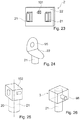
- FIG. 6 a side view of an alternative connector
- FIGS. 7 and 8 vertical cross sections of yet further connectors
- FIG. 9 a vertical cross section through another connector and a second object
- FIG. 10 a vertical cross section through a distal portion of a sonotrode
- FIGS. 11-13 vertical cross sections through connectors or portions thereof
- FIGS. 14 and 15 horizontal cross sections through connectors
- FIG. 16 a vertical cross section through an even further connector
- FIGS. 17-19 vertical cross sections through arrangements with further connectors
- FIG. 20 a view of a connector
- FIG. 21 a vertical cross section and a guiding hole geometry of an even further connector
- FIG. 22 a vertical cross section through a connector and a sonotrode
- FIGS. 23-26 views of further connectors
- FIG. 27 a vertical cross section through an even further connector
- FIGS. 28 and 29 partial horizontal cross sections of the connector of FIG. 27 ;
- FIGS. 30 and 31 horizontal cross sections through further connectors
- FIG. 32 a vertical cross section through yet another connector
- FIG. 33 in vertical cross section, a further arrangement with a connector
- FIGS. 34 and 35 partial vertical cross sections of even further connectors
- FIG. 36 a horizontal cross section through a connector
- FIGS. 37 and 38 views of embodiments of connectors
- FIGS. 39 and 40 partial vertical cross sections through an even further arrangement with a connector
- FIG. 41 a horizontal cross section through a part of a first object being a sandwich board.
- FIG. 42 a vertical cross section through an arrangement with a sandwich board as illustrated in FIG. 39 .
- FIG. 1 shows a first object 1 being a sandwich board with a first building layer 11 , a second building layer 12 , and an interlining 13 between the building layers.
- the building layers may be of a fiber composite, such as a glass fiber composite.
- the building layers will, for example, not be liquefiable under the conditions that apply during the process described herein, i.e. do not have any thermoplastic properties or be liquefiable only at temperatures substantially above the temperatures at which the liquefiable material of the connector liquefies.
- the building layers may be homogeneous or may themselves be layered thus heterogeneous.
- the interlining 13 constitutes a low density layer. In the depicted embodiment, it includes an arrangement of cardboard walls 16 extending essentially vertically, i.e. perpendicularly to the building layers.
- FIGS. 2-4 depict, by showing schematical horizontal cross sections across the interlining 13 , possible structures of such vertically extending wall elements, including corrugated ( FIG. 2 ), honeycomb ( FIG. 3 ), and triangle structure ( FIG. 4 ); many other structures are possible.
- the interlining 13 may also be of another material, such as of plastics or of a composite. Also a foam interlining is possible.
- the interlining further includes an adhesive 14 .
- the adhesive 14 is a foam, for example a foam based on polyurethane (PUR).
- the adhesive may be a thermoplastic adhesive, such as a thermoplastic polyurethane foam.
- the adhesive may also be of a not thermoplastic material, for example a thermosetting polyurethane.
- Additional elements such as a barrier foil/web of the interlining at the interface to the building layer(s) may be present.
- FIG. 5 a shows the configuration of the first object 1 , the connector 2 and a tool, namely a sonotrode 6 , at the onset of the process.
- the face of the first object 1 that in the depicted orientation in the figures is the upper face is denoted as the proximally facing face in this text.
- the connector 2 is bonded to the first object 1 from the proximal side.
- the second building layer 12 of the first object is locally removed to yield an access hole 71 underneath which the interlining 13 is exposed.
- the access hole has an (average) diameter do and a shape adapted to the shape of the connector. For example, if the connector is symmetrical about an insertion axis the access hole 71 may be circular.
- the access hole 71 may, for example, be produced by drilling.
- the connector 2 has a distal portion 21 , here being essentially tube shaped with a wall that tapers towards the distal end to form a distal edge 23 , and further has a proximal portion 22 that forms a proximally facing coupling face for the sonotrode 6 .
- the connector 2 of includes thermoplastic material at least on a distal end thereof. It may for example consist of the thermoplastic material.
- the proximal portion has a through opening 24 whereby the connector as a whole is cannulated along the axial direction.
- An average outer diameter of the connector d c may optionally be slightly larger than the diameter of the opening, whereby the opening is slightly undersized.
- the sonotrode may include a (not shown) protrusion cooperating with the opening 24 to guide the connector 2 during the process.
- a length L of the connector 2 is chosen to be greater than a total thickness t i of the interlining 13 , and also greater than a total thickness of the interlining plus the second building layer 12 .
- the sonotrode 6 is pressed against the proximally facing coupling face, and mechanical vibrations are coupled into the sonotrode, for example as soon as a certain trigger pressing force has been reached.
- the joint application of the vibration and of the pressing force cause the following (compare FIG. 5 b ):
- the distal end of the connector 2 is pressed into the material of the interlining thereby disrupting (cutting/rupturing etc.) portions of the interlining 13 and especially deforming wall portions 16 to run into directions different from vertical. Thereby, at positions where the connector 2 is pressed into the interlining 13 , a compressed portion 19 of the interlining 13 is caused.
- Thermoplastic material of the connector 2 is caused to become flowable (yielding the flow portion) and to penetrate into structures of the interlining 13 , including structures of the compressed portion 19 .
- the flow portion in the depicted embodiment includes a main flow portion 26 that is formed towards the first building layer 11 and an optional additional flow portion 27 that is caused at the rim of the second building layer 12 because of the undersized opening.
- the adhesive 14 is of a thermoplastic material capable of welding to the thermoplastic material of the connector, a weld is caused between the flow portion and the adhesive 14 .
- an adhesive connection may be caused between the flow portion and the adhesive.
- the adhesive properties of the material pairing including the adhesive and the thermoplastic material of the connector of course depend on the chosen material and thereby may be tailored by choosing the appropriate material pairing.
- the flow portion may be caused to penetrate (also) into structures of the adhesive 14 .
- the flow portion may be caused to penetrate into the pores of the foam (this of course does not imply that all of the flow portion ends in pores, rather generally the flow portion will flow into pores as well as hollow spaces between the adhesive and the other material of the interlining and/or into such other material, for example by cardboard soaking up thermoplastic material).
- the length of the connector L is reduced by distal portions of it becoming flowable, forming the main flow portion 26 and being displaced into the structure of the interlining, including the compressed portion 19 thereof.
- Such pre-determined condition may be:
- FIG. 5 b shows the configuration during this step of maintaining the pressing force.
- the pressing force may be kept constant or follow a certain force profile, for example the force may be chosen so that the position of the connector does not change any more or that the connector is pressed further into the interlining by a controlled movement.
- the pressing force may be maintained until the flow portion has sufficiently re-solidified for possible remaining elastic forces acting on the connector by the interlining are suppressed by the dimensional stability of the re-solidified thermoplastic material.
- thermoplastic material becomes flowable. This is due to external friction between the thermoplastic material and the interlining (and possible also between the thermoplastic material and the second building layer 12 and/or the first building layer 11 ) and internal friction within the thermoplastic material that have absorbed mechanical vibration energy and heated the flow portion up to a temperature at which it is flowable. After the re-solidification, a positive-fit connection between the connector and the material of the interlining, including the compressed portion, and possibly also between the connector and the first and/or second building layer, results, whereby the connector is anchored in the first object.
- the connector 2 shown, in a side view, in FIG. 6 differs from the connector of FIG. 5 a in that the distal edge 23 is not formed along a full closed contour but is interrupted by notches, whereby it is formed in a crown-like manner. Thereby, its energy directing characteristics are different and, depending on the first object material, may be more pronounced.
- FIG. 7 schematically depicts the option that the connector 2 in addition to a liquefiable portion (thermoplastic portion 4 ) may include a non-liquefiable portion 5 .
- this non-liquefiable portion is illustrated to be a metal nut 5 , for example of a suitable steel, including an inner thread 51 .
- a non-liquefiable portion may have any functional structure adapted to the particular needs.
- the non-liquefiable portion may include a screw sticking out of the thermoplastic portion, for example to the proximal side.
- the connector then serves as anchor for connecting another part to the first object.
- FIG. 8 illustrates the possibility that the connector is initially not one-part but includes a plurality of parts.
- the connector includes a sleeve portion 2 . 1 and a piston portion 2 . 2 .
- Both, the sleeve portion 2 . 1 and the piston portion 2 . 2 in the depicted embodiment each include a distal edge for being pressed into the interlining material and for thereby serving as an energy director.
- the piston portion 2 . 2 may be pressed into the sleeve portion 2 . 1 with mechanical vibration energy acting on the proximal end face of the piston portion. This may result in a local radial extension of the sleeve portion 2 . 1 (assisted by a slit 29 ) and ultimately in a weld between the sleeve portion and the piston portion.
- the sleeve portion 2 . 1 in FIG. 8 is illustrated to have a proximal head portion 28 that forms an outwardly protruding collar that after the anchoring process abuts against a rim around the opening of the first object.
- a further, second object with a through opening may be placed proximally on the first object and clamped between the head portion 28 and the first object to be fastened to the first object by the connector.
- Such a head portion 28 is an option also for other embodiments of the present invention than two-part connectors, including embodiments of the kind illustrated in FIG. 5 a / 5 b (then, the connector will, in the anchored condition, not be flush with the second building layer 12 but the distally facing shoulder formed by the head portion will abut against the second building layer 12 or, if applicable, the further, second object. Also in embodiments like the one of FIG. 6 or 7 or as described hereinafter, the head portion is an option.
- the connector 2 of FIG. 9 comprises, in addition to a head portion 28 for securing a second object 8 to the first object a further, optional feature (that is independent of the head portion 28 and is an option for any embodiment of the present invention).
- a further, optional feature that is independent of the head portion 28 and is an option for any embodiment of the present invention.
- the proximally facing coupling-in face of the connector 2 as a guiding indentation 81 cooperating, during the process steps, with a corresponding guiding protrusion 66 (see FIG. 10 ) of the sonotrode 6 and protruding from the coupling-out face 61 of the sonotrode.
- FIG. 11 depicts the option of a distal end section 82 of the distal portion 21 being deformed to be bent outwardly (arrows) during a the step of causing the connector to penetrate into the low density layer. This may cause a larger footprint of the anchoring that results after the process and thereby enhance the stability of the anchoring.
- the connector may be designed to be collapsible, as illustrated in FIG. 12 .
- the connector has a circumferential groove 83 that constitutes a systematical weakening at a position between the distal end section 82 that is to be deformed and the rest of the connector.
- An additional effect of a distal end of the connector being collapsible is that it may assist in causing the first building layer 11 to remain intact in the process also if the distal edge 23 is comparably sharp and hard for penetration of the low density layer.
- FIG. 13 schematically illustrates the possible concept of the connector having outwardly deformable legs 84 that after an initial softening following penetration of the first building layer become capable of being deformed, especially outwardly.
- FIG. 14 shows a horizontal cross section through the distal portion of the connector having the leg portion (along the plane X-X in FIG. 11 ).
- FIG. 15 shows a possible alternative cross section through the distal portion of the connector having the deformable legs 84 .
- FIG. 16 depicts the principle referring to a connector with two leg portions 84 , wherein the arrows show the direction of deformation after the initial softening.
- the connector 2 has a plug portion 85 distally of the collar 28 (head), which plug portion is dimensioned to have a slightly larger cross section (at least with respect to one in-plane dimension) than the opening in the second object 8 to be secured to the first object.
- the cross section of the plug portion is, however, is substantially larger than a cross section of the portion distally thereof, which distal portion 21 penetrates into the first object during the process. The plug portion towards the end of the process is pressed into the opening, wherein the mechanical vibration energy and pressing force cause a tight connection between the plug portion and the second object.
- the plug portion 85 may be circumferential and continuously compact. Alternatively, it may be structured, for example by including a plurality of radially running ribs that in addition to serving as the plug portion may have energy directing properties. This may be of special interest in case the building layer is not homogenously dense but, for example, consists of a consolidated fleece/PP/glass fiber composition.
- the tight connection between the plug portion and the second object and/or an according tight connection between the plug portion and the second building layer 12 may include one or more of: a press fit, a polymer-polymer weld connection, an interpenetration of material of the second object/first building layer by molten and re-solidified material of the plug portion.
- the connector 3 is depicted to consist of the thermoplastic material.
- connection between the plug portion and the second object 2 may cause a seal between proximally of the second object 8 (and/or the second building layer 12 ) and distally thereof.
- FIG. 18 illustrates a further example of a connector 2 with a guiding indentation 81 and a sonotrode 6 with a corresponding guiding protrusion 66 .
- the connector Distally of the guiding indentation 81 the connector also a fastening hole 88 and proximally thereof. It would alternatively also be possible to use the fastening hole as guiding indentation.
- a fastening hole extends from the proximal end inwardly.
- the fastening hole 88 may be a through hole (through opening 24 , see FIG. 5 a for example) or a blind hole ( FIG. 16 ), depending on the construction.
- a fastening hole 24 , 81 may serve for a screw or other fastener (including fastening portions of a further object to be connected to the first object) to be inserted therein, whereby the connector may serve as anchor for a further object connected to the first object. This may optionally be combined with the collar/head discussed hereinbefore that may serve for securing a second object to the first object.
- the fastening hole 81 may optionally include a thread or other fastening structure.
- the embodiment of FIG. 18 independent of the principle of the fastening hole, has an other special feature:
- the connector 2 has a head or body portion with the guiding indentation 81 and a distally protruding 21 with the distal edge 23 .
- the connector further includes a fastener receiving portion 87 that is formed as a central distal protrusion extending distally from the head or body portion.
- the fastening hole 88 there is formed the fastening hole 88 .
- the fastening hole may serve for inserting a fastener, such as a screw or a pin.
- the fastening hole may include an according structure, for example an inner thread.
- the connector may have an other fastening structure, for example a make fastening structure instead of a female fastening structure (for example a threaded bar or similar).
- An according sonotrode used may have an according indentation that receives such fastening structure and thereby avoids the direct coupling of vibration into the fastening structure.
- the connector 2 shown in FIGS. 19 and 20 is an example of a connector that in addition to an anchoring structure (which includes the thermoplastic material that during the process is made flowable and, if applicable, the punching structure) also includes a connecting structure defining a connecting location, especially a connecting location defined with respect to all dimensions (x,y.z).
- the connecting structure in the depicted embodiment is constituted by a connector peg 96 one-piece with the anchoring structure.
- the connecting structure is especially such that it is arranged laterally. This means that the arrangement of the connecting structure 96 is not symmetrical with respect to the insertion axis 20 but is off-center with respect to the axis 20 .
- the insertion axis 20 is the axis along which generally the pressing force is applied during insertion and along which the movement during insertion will take place at least predominantly.
- the insertion axis 20 is generally central with respect to the punched-out portion.
- the position of the connecting location depends on the angle of rotation around the axis 20 .
- the connector relative when the connector relative is positioned relative to the first object and anchored therein, not only the position but also its orientation may have to be defined.
- An example of an according connecting structure may, for example, be a structure (like the peg) that protrudes away from the anchoring structure into a defined direction, such as a pivot of a hinge or similar, a structure for clipping an other item onto, an anchor for a thread connection, etc.
- the connector 2 of FIGS. 19 and 20 includes a plate-like body portion 22 defining a distally facing abutment face 98 . From the abutment face 98 , a distal portion 21 having the distal edge 23 protrudes towards distally. Towards proximally, the connector includes a base wall 95 from which the connecting peg 96 protrudes laterally. The base wall 95 is arranged off-center with respect to the axis 20 . Further, the connector includes a plurality of reinforcing walls 92 extending perpendicularly to the base wall 95 and enhancing the mechanical stability with respect to forces acting on the connecting peg.
- the distally facing abutment face defines the z position of the connecting structure after the process in that the pressing force is applied until the abutment face 98 abuts against a proximally facing surface portion of the object.
- the connector 2 in the embodiment of FIGS. 19 and 20 as well as the connectors of the embodiments of FIGS. 21 and 21 hereinafter may, for example, be a mount of a rear parcel shelf of an automobile.
- the sonotrode 6 used for anchoring the connector may be shaped to be adapted to the shape of the connector.
- the connector may be shaped to impinge, from proximally, on the body portion 22 by engaging between the reinforcing walls 92 and the base wall 95 .
- it would also be possible to provide a protruding collar 91 of the connector 2 as shown in dotted lines in FIG. 19 .
- the arrangement with the sonotrode engaging between the walls directly on the body portion 22 with the sonotrode having indentations for reinforcing wall(s) if necessary, though, features the advantage that the pressing force and vibration are coupled straight into the anchoring portion.
- the base wall 95 and/or the reinforcing walls 92 may be used for this, together with a corresponding shape of the sonotrode, whereby the orientation of the sonotrode defines the orientation of the connector.
- the connector and the sonotrode may include guiding structures that are not circularly symmetrical, such as a rectangular guiding protrusion of the sonotrode engaging with a corresponding guiding indentation 81 of the connector.
- guiding protrusion and guiding indentation are possible, including any shapes known for screw heads, including hexagonal, star-shaped, etc.
- FIG. 21 includes an annular base wall 95 from which the connecting peg 96 protrudes outwardly, the base wall following a, for example, circular or rectangular contour and thereby defining a pot-like structure with the connector body defining the bottom of the pot, wherein the sonotrode during the process is pressed against this bottom.
- the embodiment of a connector sketched in FIG. 22 has a proximal portion similar to the corresponding structure of the embodiment of FIG. 21 , but with a base wall that is not annular.
- the anchoring structure includes an anchoring structure distal portion 21 that has the shape of a tapering pin, optionally with a plurality of axially running energy directors, namely wings 99 , protruding radially.
- FIGS. 19-22 include using a sonotrode adapted to the geometry of the connector. This is not always necessary.
- FIG. 23 shows an embodiment in which the body portion 22 forms a generally flat coupling surface for a generic sonotrode.
- FIG. 23 has additional features that can be realized independently or in combination with each other and/or with other features illustrated in FIG. 23 :
- FIG. 24 shows a connector that is based on the principle described referring to FIGS. 19-22 .
- the connecting structure is not a peg but a fastening hole in the base wall 95 .
- the connector instead of the plate-like body portion and the walls (ribs) shown in FIGS. 19-24 , the connector has a closed housing 102 that is for example either itself off-center with respect to the insertion axis or that houses a functional structure that is off-center with respect to this axis, or both.
- FIG. 25 the functional structure that is off-center with respect to the axis 20 is not a connecting structure but another functional part.
- FIG. 25 very schematically illustrates two parts shown in dotted lines within the housing.
- Such functional structure may include a sensor, an antenna, a light source, a camera, an acoustic converter etc.
- Embodiments with a closed housing as shown in FIG. 25 may be provided with means for coupling the vibration energy from the proximally facing end face of the housing to the distal portion (distal anchoring portion) 21 , for example tube portion.
- FIG. 26 illustrates an example of a connector 2 —that in the depicted embodiment has a connecting peg 96 —of which the distal portion 21 extends through the housing to the proximal end face of the connector.
- the housing in this may be open towards distally. If the housing is open distally, the abutment portion of the functional portion is constituted by the distal edges of the vertical walls of the housing.
- the tube-like distal portion 21 is stabilized by at least one stabilizer rib 111 .
- such stabilizer structure may prevent the tube portion (that optionally may include a plurality of legs) from collapsing during the initial stage of being pressed into the low density layer.
- the stabilizer structure may in addition be shaped so as to exert an outwardly (with respect to radial directions) directed pressure during the step of pressing the connector into the low density layer.
- the bow-shaped, concave contour in the illustrated example will cause such outward pressure when the connector is pressed into material of the low density layer, as illustrated by the arrows in FIG. 27 .
- FIG. 28 showing a detail of a possible cross section along the plane A-A in FIG. 27 , illustrates that the distal anchoring portion 21 of a connector does not need to be circular in cross section. Rather, in the embodiment of FIG. 28 , the connector has an axially running notch at the position where a stabilizer rib 11 is connected to the tube—shaped part of the anchoring portion 21 . By this, an outward pressing of the thermoplastic material of the anchoring portion by the directed pressure may be favored.
- FIG. 29 shows a detail of a possible cross section along the plane B-B in FIG. 27 .
- the circumferential groove 83 need not necessarily run around the entire periphery but may be interrupted, especially where a stabilizer rib 111 is connected to the tube portion.
- FIG. 30 shows a possible horizontal cross section through a connector.
- the combination of a circular geometry and the stabilizer ribs 111 in a crossed arrangement is especially stable.
- FIG. 31 illustrates a cross section of a cross section through an alternative anchoring portion, which anchoring portion does not have circular symmetry but is oblong in cross section.
- a stabilizer structure such as a stabilizer rib 111 arranged as shown in FIG. 31 may be advantageous.
- FIG. 32 illustrates a connector that has a stabilizer rib 111 that is pointed towards a distally facing tip 115 or edge so that interlining material penetrated by the connector during the process is forced into the direction of the arrows and thereby exerts an outward pressure on the tube shaped part of the anchoring portion 21 or the legs, respectively.
- FIG. 33 deals with a situation in which the object has a proximal, second building layer, and the access hole in the second building layer 12 has a diameter approximately corresponding to a diameter of the distal part of the anchoring portion 21 .
- the connector in addition to the collar 28 has a step feature 121 forming a shoulder of the distal portion 21 on the radial-outer side. This step feature will come into physical contact with the second building layer 12 as soon as the connector has advanced into the first object 1 to a sufficient extent, especially towards the end of the forward (towards distally) movement. As a consequence, due to friction between the vibrating connector and the second building layer 12 , energy will be absorbed, and thermoplastic material of the connector becomes flowable near the second building layer.
- the flow portion will therefore include portions in a proximal region and especially immediately distally of the first building layer. This may come in addition or as an alternative to the measures, for example, described referring to FIG. 27 or 32 which measures also contribute to a generation of a flow portion and a radial flow immediately distally of the second building layer 12 .
- the connector 2 may include an outward taper 122 , as shown in FIG. 34 .
- the connector may include an inner feature, such as an inner groove 129 assisting the collapse immediately distally of the second building layer.
- FIG. 35 illustrates an example. Other structures, including measures described hereinbefore, may optionally be combined with this.
- FIG. 36 schematically illustrating a top view (view from the proximal side) of the connector 3 shows the principle that the mentioned outward features (step 121 , taper 122 ) may be formed as radial protrusions, for example distributed around the periphery. As an alternative, such outward features may also be circumferential, i.e. extend continuously around the periphery.
- FIGS. 37 and 38 show examples of connectors 2 based on the principles described referring to FIGS. 34-36 .
- Further examples include connectors with an outward taper 122 with smooth outer surface, i.e. without the axially running ribs that form the taper.
- the tapered section may reach essentially to the distal end (as in FIG. 37 ) or alternatively may be restricted to a more proximal region (as in FIG. 38 ).
- FIG. 39 schematically illustrates a further variant in which a second object 8 is attached to the first object by the connector.
- an adhesive 141 for example in a flowable state, is applied between the first and second objects.
- an adhesive connection and the concept of securing the second object by a connector according to the invention are combined. This may, for example, be useful if in a manufacturing process the second object is glued to the first object by the adhesive, but the assembly of the first and second objects are to be processed immediately after having been assembled together.
- the connector applied according to the invention provides initial stability sufficient for subsequent production steps.
- the energy input and pressing force during the final stage of the hereinbefore described anchoring process may cause a flow of the adhesive applied between the first and second objects (and/or between the distal surface of the collar 28 (if any) and the second object, in special embodiments). This may be used in the following manner:
- the first object may, for example, be a structure of a low density foam layer, wherein the foam material is, for example, plastically deformable, supported by a first building layer and, for example, sandwiched between such first building layer and a second building layer.
- the hereinbefore described embodiments generally include the step of deforming discrete elements of the low density layer, which deformed elements then become part of an intertwined structure with the liquefiable material to anchor the connector in the first element.
- the deformation of the discrete elements may make a substantial contribution to the anchoring strength in that it contributes to a higher density and/or forms macroscopic undercuts.
- FIGS. 41 and 42 show a horizontal section through a low density layer with a honeycomb structure.
- the discrete elements are vertical walls of for example cardboard or a plastic or a plastic composite. Due to the honeycomb structure, they are comparably stable with respect to deformations.
- the circular line 201 in FIG. 41 illustrates the possible position of a distal connector end face that may be pressed into the low density layer.
- FIG. 42 illustrates the connector 2 anchored in the first object after the thermoplastic material has re-solidified.
- the discrete elements 16 integrated into material of the connector still form essentially vertical walls.
- the anchoring may be caused by a combination of:
Landscapes
- Engineering & Computer Science (AREA)
- Mechanical Engineering (AREA)
- General Engineering & Computer Science (AREA)
- Standing Axle, Rod, Or Tube Structures Coupled By Welding, Adhesion, Or Deposition (AREA)
- Lining Or Joining Of Plastics Or The Like (AREA)
- Connector Housings Or Holding Contact Members (AREA)
- Manufacturing Of Electrical Connectors (AREA)
- Connection Of Plates (AREA)
Applications Claiming Priority (3)
| Application Number | Priority Date | Filing Date | Title |
|---|---|---|---|
| CH9472016 | 2016-07-21 | ||
| CH00947/16 | 2016-07-21 | ||
| PCT/EP2017/068455 WO2018015527A1 (en) | 2016-07-21 | 2017-07-21 | Securing a second object to a first object |
Publications (2)
| Publication Number | Publication Date |
|---|---|
| US20190168464A1 US20190168464A1 (en) | 2019-06-06 |
| US11084226B2 true US11084226B2 (en) | 2021-08-10 |
Family
ID=56615794
Family Applications (1)
| Application Number | Title | Priority Date | Filing Date |
|---|---|---|---|
| US16/318,236 Active 2038-02-19 US11084226B2 (en) | 2016-07-21 | 2017-07-21 | Securing a second object to a first object |
Country Status (8)
| Country | Link |
|---|---|
| US (1) | US11084226B2 (enExample) |
| EP (1) | EP3487686B1 (enExample) |
| JP (1) | JP2019527155A (enExample) |
| KR (1) | KR20190043133A (enExample) |
| CN (1) | CN109789640B (enExample) |
| BR (1) | BR112019001014A2 (enExample) |
| MX (1) | MX389481B (enExample) |
| WO (1) | WO2018015527A1 (enExample) |
Cited By (4)
| Publication number | Priority date | Publication date | Assignee | Title |
|---|---|---|---|---|
| US20220212725A1 (en) * | 2018-08-23 | 2022-07-07 | Gemini Group, Inc. | Multi-dimensional load structure |
| US11472124B2 (en) * | 2016-03-21 | 2022-10-18 | Multimaterial-Welding Ag | Securing a second object to a first object |
| US12280552B2 (en) * | 2021-07-02 | 2025-04-22 | Multimaterial-Welding Ag | Connector element and method of bonding such connector element to a substrate |
| US12485974B2 (en) | 2018-08-23 | 2025-12-02 | Gemini Group, Inc. | Multi-dimensional load structure |
Families Citing this family (6)
| Publication number | Priority date | Publication date | Assignee | Title |
|---|---|---|---|---|
| DE102017008170A1 (de) * | 2017-08-31 | 2019-02-28 | Webasto SE | Kunststoffbauteil mit daran verankertem Anbauteil |
| CN112638629B (zh) * | 2018-07-13 | 2023-06-06 | 伍德韦尔丁公司 | 锚固连接件 |
| CN113439166A (zh) * | 2019-02-18 | 2021-09-24 | 多材料焊接有限公司 | 将第一物体锚固在第二物体中 |
| CN113892107A (zh) | 2019-05-24 | 2022-01-04 | 多材料焊接有限公司 | 连接物至物体的超声波装配 |
| US12384117B2 (en) | 2019-11-29 | 2025-08-12 | Multimaterial-Welding Ag | Securing a second object to a first object |
| US20220090619A1 (en) * | 2020-09-24 | 2022-03-24 | Ford Global Technologies, Llc | Grooved self piercing rivet |
Citations (12)
| Publication number | Priority date | Publication date | Assignee | Title |
|---|---|---|---|---|
| US4027370A (en) | 1976-10-21 | 1977-06-07 | Branson Ultrasonics Corporation | High frequency vibration insertion apparatus |
| WO1993012344A1 (de) | 1991-12-17 | 1993-06-24 | Ejot Eberhard Jaeger Gmbh & Co. Kg | Verfahren zum befestigen eines halteteils in einer ausnehmung eines bauteils |
| WO1998042988A1 (de) | 1997-03-21 | 1998-10-01 | Creaholic S.A. | Verfahren zur verankerung von verbindungselementen in einem material mit poren oder hohlräumen sowie verbindungselemente für die verankerung |
| US5965238A (en) | 1995-11-14 | 1999-10-12 | Kishimoto Sangyo Co., Ltd. | Synthetic resin panel welding method and hollow panel structures fabricated by the method |
| WO2000079137A1 (de) | 1999-06-18 | 2000-12-28 | Woodwelding Ag | Stoffschlüssiges verbinden |
| GB2421556A (en) * | 2004-12-27 | 2006-06-28 | Blum Gmbh Julius | Method of anchoring a plug element in a building board |
| WO2008080238A1 (en) | 2006-12-28 | 2008-07-10 | Woodwelding Ag | Method for anchoring a joining element in an object and joining element to be used in the method |
| WO2010072009A1 (en) | 2008-12-23 | 2010-07-01 | Woodwelding Ag | Method of anchoring a connector, and connector |
| US7807093B2 (en) * | 2003-10-27 | 2010-10-05 | Fits Holding B.V. | Method for arranging a thermoplastic insert in a thermoplastic sandwich product |
| WO2015135824A1 (de) | 2014-03-11 | 2015-09-17 | Ejot Gmbh & Co. Kg | Verfahren zum verbinden von bauteilen von denen eines aus einem faserverstärkten kunststoff besteht |
| WO2015162029A1 (de) | 2014-04-23 | 2015-10-29 | Weber Schraubautomaten Gmbh | Vorrichtung zum setzen eines setzelements in einem bauteil |
| WO2017162693A1 (en) | 2016-03-21 | 2017-09-28 | Multimaterial-Welding Ag | Securing a second object to a first object |
-
2017
- 2017-07-21 CN CN201780054793.7A patent/CN109789640B/zh active Active
- 2017-07-21 KR KR1020197004308A patent/KR20190043133A/ko not_active Abandoned
- 2017-07-21 EP EP17742431.4A patent/EP3487686B1/en active Active
- 2017-07-21 US US16/318,236 patent/US11084226B2/en active Active
- 2017-07-21 WO PCT/EP2017/068455 patent/WO2018015527A1/en not_active Ceased
- 2017-07-21 BR BR112019001014A patent/BR112019001014A2/pt active Search and Examination
- 2017-07-21 MX MX2019000817A patent/MX389481B/es unknown
- 2017-07-21 JP JP2019502668A patent/JP2019527155A/ja active Pending
Patent Citations (13)
| Publication number | Priority date | Publication date | Assignee | Title |
|---|---|---|---|---|
| US4027370A (en) | 1976-10-21 | 1977-06-07 | Branson Ultrasonics Corporation | High frequency vibration insertion apparatus |
| WO1993012344A1 (de) | 1991-12-17 | 1993-06-24 | Ejot Eberhard Jaeger Gmbh & Co. Kg | Verfahren zum befestigen eines halteteils in einer ausnehmung eines bauteils |
| US5965238A (en) | 1995-11-14 | 1999-10-12 | Kishimoto Sangyo Co., Ltd. | Synthetic resin panel welding method and hollow panel structures fabricated by the method |
| WO1998042988A1 (de) | 1997-03-21 | 1998-10-01 | Creaholic S.A. | Verfahren zur verankerung von verbindungselementen in einem material mit poren oder hohlräumen sowie verbindungselemente für die verankerung |
| WO2000079137A1 (de) | 1999-06-18 | 2000-12-28 | Woodwelding Ag | Stoffschlüssiges verbinden |
| US7807093B2 (en) * | 2003-10-27 | 2010-10-05 | Fits Holding B.V. | Method for arranging a thermoplastic insert in a thermoplastic sandwich product |
| DE102005060528A1 (de) | 2004-12-27 | 2006-07-06 | Julius Blum Gmbh | Verfahren zum Befestigen eines Einsatzkörpers in einer Leichtbauplatte |
| GB2421556A (en) * | 2004-12-27 | 2006-06-28 | Blum Gmbh Julius | Method of anchoring a plug element in a building board |
| WO2008080238A1 (en) | 2006-12-28 | 2008-07-10 | Woodwelding Ag | Method for anchoring a joining element in an object and joining element to be used in the method |
| WO2010072009A1 (en) | 2008-12-23 | 2010-07-01 | Woodwelding Ag | Method of anchoring a connector, and connector |
| WO2015135824A1 (de) | 2014-03-11 | 2015-09-17 | Ejot Gmbh & Co. Kg | Verfahren zum verbinden von bauteilen von denen eines aus einem faserverstärkten kunststoff besteht |
| WO2015162029A1 (de) | 2014-04-23 | 2015-10-29 | Weber Schraubautomaten Gmbh | Vorrichtung zum setzen eines setzelements in einem bauteil |
| WO2017162693A1 (en) | 2016-03-21 | 2017-09-28 | Multimaterial-Welding Ag | Securing a second object to a first object |
Non-Patent Citations (2)
| Title |
|---|
| English translation of International Preliminary Report on Patentability dated Jan. 22, 2019 (Jan. 22, 2019), Application No. PCT/EP2017/068455, 9 pages. |
| Switzerland Search Report dated Oct. 28, 2016, Application No. CH 9472016, 3 pages. |
Cited By (5)
| Publication number | Priority date | Publication date | Assignee | Title |
|---|---|---|---|---|
| US11472124B2 (en) * | 2016-03-21 | 2022-10-18 | Multimaterial-Welding Ag | Securing a second object to a first object |
| US20220212725A1 (en) * | 2018-08-23 | 2022-07-07 | Gemini Group, Inc. | Multi-dimensional load structure |
| US12365395B2 (en) * | 2018-08-23 | 2025-07-22 | Gemini Group, Inc. | Multi-dimensional load structure |
| US12485974B2 (en) | 2018-08-23 | 2025-12-02 | Gemini Group, Inc. | Multi-dimensional load structure |
| US12280552B2 (en) * | 2021-07-02 | 2025-04-22 | Multimaterial-Welding Ag | Connector element and method of bonding such connector element to a substrate |
Also Published As
| Publication number | Publication date |
|---|---|
| EP3487686C0 (en) | 2026-02-25 |
| JP2019527155A (ja) | 2019-09-26 |
| US20190168464A1 (en) | 2019-06-06 |
| MX2019000817A (es) | 2019-06-03 |
| WO2018015527A1 (en) | 2018-01-25 |
| KR20190043133A (ko) | 2019-04-25 |
| EP3487686A1 (en) | 2019-05-29 |
| MX389481B (es) | 2025-03-20 |
| CN109789640A (zh) | 2019-05-21 |
| EP3487686B1 (en) | 2026-02-25 |
| CN109789640B (zh) | 2021-12-28 |
| BR112019001014A2 (pt) | 2019-05-14 |
Similar Documents
| Publication | Publication Date | Title |
|---|---|---|
| US11084226B2 (en) | Securing a second object to a first object | |
| US11472124B2 (en) | Securing a second object to a first object | |
| US11345096B2 (en) | Anchoring in a lightweight building element | |
| AU2015341864B2 (en) | Bonding objects together | |
| US11203166B2 (en) | Securing a second object to a first object | |
| US12280552B2 (en) | Connector element and method of bonding such connector element to a substrate |
Legal Events
| Date | Code | Title | Description |
|---|---|---|---|
| FEPP | Fee payment procedure |
Free format text: ENTITY STATUS SET TO UNDISCOUNTED (ORIGINAL EVENT CODE: BIG.); ENTITY STATUS OF PATENT OWNER: LARGE ENTITY |
|
| STPP | Information on status: patent application and granting procedure in general |
Free format text: DOCKETED NEW CASE - READY FOR EXAMINATION |
|
| AS | Assignment |
Owner name: MULTIMATERIAL-WELDING AG, SWITZERLAND Free format text: ASSIGNMENT OF ASSIGNORS INTEREST;ASSIGNORS:POSCHNER, PATRICIA;KVIST, JOAKIM;MOOSER, PATRICK;REEL/FRAME:049835/0633 Effective date: 20190129 |
|
| STPP | Information on status: patent application and granting procedure in general |
Free format text: NON FINAL ACTION MAILED |
|
| STPP | Information on status: patent application and granting procedure in general |
Free format text: RESPONSE TO NON-FINAL OFFICE ACTION ENTERED AND FORWARDED TO EXAMINER |
|
| STPP | Information on status: patent application and granting procedure in general |
Free format text: NOTICE OF ALLOWANCE MAILED -- APPLICATION RECEIVED IN OFFICE OF PUBLICATIONS |
|
| STPP | Information on status: patent application and granting procedure in general |
Free format text: AWAITING TC RESP., ISSUE FEE NOT PAID |
|
| STPP | Information on status: patent application and granting procedure in general |
Free format text: NOTICE OF ALLOWANCE MAILED -- APPLICATION RECEIVED IN OFFICE OF PUBLICATIONS |
|
| STPP | Information on status: patent application and granting procedure in general |
Free format text: PUBLICATIONS -- ISSUE FEE PAYMENT RECEIVED |
|
| STPP | Information on status: patent application and granting procedure in general |
Free format text: PUBLICATIONS -- ISSUE FEE PAYMENT VERIFIED |
|
| STCF | Information on status: patent grant |
Free format text: PATENTED CASE |
|
| AS | Assignment |
Owner name: MULTIMATERIAL-WELDING AG, SWITZERLAND Free format text: CHANGE OF ADDRESS;ASSIGNOR:MULTIMATERIAL-WELDING AG;REEL/FRAME:059334/0324 Effective date: 20220307 |
|
| MAFP | Maintenance fee payment |
Free format text: PAYMENT OF MAINTENANCE FEE, 4TH YEAR, LARGE ENTITY (ORIGINAL EVENT CODE: M1551); ENTITY STATUS OF PATENT OWNER: LARGE ENTITY Year of fee payment: 4 |