US11083604B2 - Preventing stent failure using adaptive shear responsive endovascular implant - Google Patents
Preventing stent failure using adaptive shear responsive endovascular implant Download PDFInfo
- Publication number
- US11083604B2 US11083604B2 US16/251,624 US201916251624A US11083604B2 US 11083604 B2 US11083604 B2 US 11083604B2 US 201916251624 A US201916251624 A US 201916251624A US 11083604 B2 US11083604 B2 US 11083604B2
- Authority
- US
- United States
- Prior art keywords
- stent
- information
- flow sensors
- control system
- heaters
- Prior art date
- Legal status (The legal status is an assumption and is not a legal conclusion. Google has not performed a legal analysis and makes no representation as to the accuracy of the status listed.)
- Active, expires
Links
Images


Classifications
-
- A—HUMAN NECESSITIES
- A61—MEDICAL OR VETERINARY SCIENCE; HYGIENE
- A61F—FILTERS IMPLANTABLE INTO BLOOD VESSELS; PROSTHESES; DEVICES PROVIDING PATENCY TO, OR PREVENTING COLLAPSING OF, TUBULAR STRUCTURES OF THE BODY, e.g. STENTS; ORTHOPAEDIC, NURSING OR CONTRACEPTIVE DEVICES; FOMENTATION; TREATMENT OR PROTECTION OF EYES OR EARS; BANDAGES, DRESSINGS OR ABSORBENT PADS; FIRST-AID KITS
- A61F2/00—Filters implantable into blood vessels; Prostheses, i.e. artificial substitutes or replacements for parts of the body; Appliances for connecting them with the body; Devices providing patency to, or preventing collapsing of, tubular structures of the body, e.g. stents
- A61F2/82—Devices providing patency to, or preventing collapsing of, tubular structures of the body, e.g. stents
- A61F2/86—Stents in a form characterised by the wire-like elements; Stents in the form characterised by a net-like or mesh-like structure
- A61F2/90—Stents in a form characterised by the wire-like elements; Stents in the form characterised by a net-like or mesh-like structure characterised by a net-like or mesh-like structure
-
- A—HUMAN NECESSITIES
- A61—MEDICAL OR VETERINARY SCIENCE; HYGIENE
- A61L—METHODS OR APPARATUS FOR STERILISING MATERIALS OR OBJECTS IN GENERAL; DISINFECTION, STERILISATION OR DEODORISATION OF AIR; CHEMICAL ASPECTS OF BANDAGES, DRESSINGS, ABSORBENT PADS OR SURGICAL ARTICLES; MATERIALS FOR BANDAGES, DRESSINGS, ABSORBENT PADS OR SURGICAL ARTICLES
- A61L31/00—Materials for other surgical articles, e.g. stents, stent-grafts, shunts, surgical drapes, guide wires, materials for adhesion prevention, occluding devices, surgical gloves, tissue fixation devices
- A61L31/04—Macromolecular materials
-
- A—HUMAN NECESSITIES
- A61—MEDICAL OR VETERINARY SCIENCE; HYGIENE
- A61B—DIAGNOSIS; SURGERY; IDENTIFICATION
- A61B5/00—Measuring for diagnostic purposes; Identification of persons
- A61B5/02—Detecting, measuring or recording for evaluating the cardiovascular system, e.g. pulse, heart rate, blood pressure or blood flow
- A61B5/026—Measuring blood flow
-
- A—HUMAN NECESSITIES
- A61—MEDICAL OR VETERINARY SCIENCE; HYGIENE
- A61B—DIAGNOSIS; SURGERY; IDENTIFICATION
- A61B5/00—Measuring for diagnostic purposes; Identification of persons
- A61B5/48—Other medical applications
- A61B5/4851—Prosthesis assessment or monitoring
-
- A—HUMAN NECESSITIES
- A61—MEDICAL OR VETERINARY SCIENCE; HYGIENE
- A61B—DIAGNOSIS; SURGERY; IDENTIFICATION
- A61B5/00—Measuring for diagnostic purposes; Identification of persons
- A61B5/68—Arrangements of detecting, measuring or recording means, e.g. sensors, in relation to patient
- A61B5/6846—Arrangements of detecting, measuring or recording means, e.g. sensors, in relation to patient specially adapted to be brought in contact with an internal body part, i.e. invasive
- A61B5/6847—Arrangements of detecting, measuring or recording means, e.g. sensors, in relation to patient specially adapted to be brought in contact with an internal body part, i.e. invasive mounted on an invasive device
- A61B5/6862—Stents
-
- A—HUMAN NECESSITIES
- A61—MEDICAL OR VETERINARY SCIENCE; HYGIENE
- A61B—DIAGNOSIS; SURGERY; IDENTIFICATION
- A61B5/00—Measuring for diagnostic purposes; Identification of persons
- A61B5/68—Arrangements of detecting, measuring or recording means, e.g. sensors, in relation to patient
- A61B5/6846—Arrangements of detecting, measuring or recording means, e.g. sensors, in relation to patient specially adapted to be brought in contact with an internal body part, i.e. invasive
- A61B5/6867—Arrangements of detecting, measuring or recording means, e.g. sensors, in relation to patient specially adapted to be brought in contact with an internal body part, i.e. invasive specially adapted to be attached or implanted in a specific body part
- A61B5/6876—Blood vessel
-
- A—HUMAN NECESSITIES
- A61—MEDICAL OR VETERINARY SCIENCE; HYGIENE
- A61F—FILTERS IMPLANTABLE INTO BLOOD VESSELS; PROSTHESES; DEVICES PROVIDING PATENCY TO, OR PREVENTING COLLAPSING OF, TUBULAR STRUCTURES OF THE BODY, e.g. STENTS; ORTHOPAEDIC, NURSING OR CONTRACEPTIVE DEVICES; FOMENTATION; TREATMENT OR PROTECTION OF EYES OR EARS; BANDAGES, DRESSINGS OR ABSORBENT PADS; FIRST-AID KITS
- A61F2/00—Filters implantable into blood vessels; Prostheses, i.e. artificial substitutes or replacements for parts of the body; Appliances for connecting them with the body; Devices providing patency to, or preventing collapsing of, tubular structures of the body, e.g. stents
- A61F2/02—Prostheses implantable into the body
- A61F2/04—Hollow or tubular parts of organs, e.g. bladders, tracheae, bronchi or bile ducts
- A61F2/06—Blood vessels
- A61F2/07—Stent-grafts
-
- A—HUMAN NECESSITIES
- A61—MEDICAL OR VETERINARY SCIENCE; HYGIENE
- A61L—METHODS OR APPARATUS FOR STERILISING MATERIALS OR OBJECTS IN GENERAL; DISINFECTION, STERILISATION OR DEODORISATION OF AIR; CHEMICAL ASPECTS OF BANDAGES, DRESSINGS, ABSORBENT PADS OR SURGICAL ARTICLES; MATERIALS FOR BANDAGES, DRESSINGS, ABSORBENT PADS OR SURGICAL ARTICLES
- A61L31/00—Materials for other surgical articles, e.g. stents, stent-grafts, shunts, surgical drapes, guide wires, materials for adhesion prevention, occluding devices, surgical gloves, tissue fixation devices
- A61L31/02—Inorganic materials
- A61L31/022—Metals or alloys
-
- A—HUMAN NECESSITIES
- A61—MEDICAL OR VETERINARY SCIENCE; HYGIENE
- A61L—METHODS OR APPARATUS FOR STERILISING MATERIALS OR OBJECTS IN GENERAL; DISINFECTION, STERILISATION OR DEODORISATION OF AIR; CHEMICAL ASPECTS OF BANDAGES, DRESSINGS, ABSORBENT PADS OR SURGICAL ARTICLES; MATERIALS FOR BANDAGES, DRESSINGS, ABSORBENT PADS OR SURGICAL ARTICLES
- A61L31/00—Materials for other surgical articles, e.g. stents, stent-grafts, shunts, surgical drapes, guide wires, materials for adhesion prevention, occluding devices, surgical gloves, tissue fixation devices
- A61L31/14—Materials characterised by their function or physical properties, e.g. injectable or lubricating compositions, shape-memory materials, surface modified materials
-
- B—PERFORMING OPERATIONS; TRANSPORTING
- B33—ADDITIVE MANUFACTURING TECHNOLOGY
- B33Y—ADDITIVE MANUFACTURING, i.e. MANUFACTURING OF THREE-DIMENSIONAL [3D] OBJECTS BY ADDITIVE DEPOSITION, ADDITIVE AGGLOMERATION OR ADDITIVE LAYERING, e.g. BY 3D PRINTING, STEREOLITHOGRAPHY OR SELECTIVE LASER SINTERING
- B33Y10/00—Processes of additive manufacturing
-
- B—PERFORMING OPERATIONS; TRANSPORTING
- B33—ADDITIVE MANUFACTURING TECHNOLOGY
- B33Y—ADDITIVE MANUFACTURING, i.e. MANUFACTURING OF THREE-DIMENSIONAL [3D] OBJECTS BY ADDITIVE DEPOSITION, ADDITIVE AGGLOMERATION OR ADDITIVE LAYERING, e.g. BY 3D PRINTING, STEREOLITHOGRAPHY OR SELECTIVE LASER SINTERING
- B33Y80/00—Products made by additive manufacturing
-
- A—HUMAN NECESSITIES
- A61—MEDICAL OR VETERINARY SCIENCE; HYGIENE
- A61B—DIAGNOSIS; SURGERY; IDENTIFICATION
- A61B2562/00—Details of sensors; Constructional details of sensor housings or probes; Accessories for sensors
- A61B2562/04—Arrangements of multiple sensors of the same type
- A61B2562/046—Arrangements of multiple sensors of the same type in a matrix array
-
- A—HUMAN NECESSITIES
- A61—MEDICAL OR VETERINARY SCIENCE; HYGIENE
- A61B—DIAGNOSIS; SURGERY; IDENTIFICATION
- A61B5/00—Measuring for diagnostic purposes; Identification of persons
- A61B5/0002—Remote monitoring of patients using telemetry, e.g. transmission of vital signals via a communication network
- A61B5/0031—Implanted circuitry
-
- A—HUMAN NECESSITIES
- A61—MEDICAL OR VETERINARY SCIENCE; HYGIENE
- A61B—DIAGNOSIS; SURGERY; IDENTIFICATION
- A61B5/00—Measuring for diagnostic purposes; Identification of persons
- A61B5/68—Arrangements of detecting, measuring or recording means, e.g. sensors, in relation to patient
- A61B5/6846—Arrangements of detecting, measuring or recording means, e.g. sensors, in relation to patient specially adapted to be brought in contact with an internal body part, i.e. invasive
- A61B5/6847—Arrangements of detecting, measuring or recording means, e.g. sensors, in relation to patient specially adapted to be brought in contact with an internal body part, i.e. invasive mounted on an invasive device
- A61B5/686—Permanently implanted devices, e.g. pacemakers, other stimulators, biochips
-
- A—HUMAN NECESSITIES
- A61—MEDICAL OR VETERINARY SCIENCE; HYGIENE
- A61F—FILTERS IMPLANTABLE INTO BLOOD VESSELS; PROSTHESES; DEVICES PROVIDING PATENCY TO, OR PREVENTING COLLAPSING OF, TUBULAR STRUCTURES OF THE BODY, e.g. STENTS; ORTHOPAEDIC, NURSING OR CONTRACEPTIVE DEVICES; FOMENTATION; TREATMENT OR PROTECTION OF EYES OR EARS; BANDAGES, DRESSINGS OR ABSORBENT PADS; FIRST-AID KITS
- A61F2/00—Filters implantable into blood vessels; Prostheses, i.e. artificial substitutes or replacements for parts of the body; Appliances for connecting them with the body; Devices providing patency to, or preventing collapsing of, tubular structures of the body, e.g. stents
- A61F2/82—Devices providing patency to, or preventing collapsing of, tubular structures of the body, e.g. stents
- A61F2002/828—Means for connecting a plurality of stents allowing flexibility of the whole structure
-
- A—HUMAN NECESSITIES
- A61—MEDICAL OR VETERINARY SCIENCE; HYGIENE
- A61F—FILTERS IMPLANTABLE INTO BLOOD VESSELS; PROSTHESES; DEVICES PROVIDING PATENCY TO, OR PREVENTING COLLAPSING OF, TUBULAR STRUCTURES OF THE BODY, e.g. STENTS; ORTHOPAEDIC, NURSING OR CONTRACEPTIVE DEVICES; FOMENTATION; TREATMENT OR PROTECTION OF EYES OR EARS; BANDAGES, DRESSINGS OR ABSORBENT PADS; FIRST-AID KITS
- A61F2210/00—Particular material properties of prostheses classified in groups A61F2/00 - A61F2/26 or A61F2/82 or A61F9/00 or A61F11/00 or subgroups thereof
- A61F2210/0014—Particular material properties of prostheses classified in groups A61F2/00 - A61F2/26 or A61F2/82 or A61F9/00 or A61F11/00 or subgroups thereof using shape memory or superelastic materials, e.g. nitinol
-
- A—HUMAN NECESSITIES
- A61—MEDICAL OR VETERINARY SCIENCE; HYGIENE
- A61F—FILTERS IMPLANTABLE INTO BLOOD VESSELS; PROSTHESES; DEVICES PROVIDING PATENCY TO, OR PREVENTING COLLAPSING OF, TUBULAR STRUCTURES OF THE BODY, e.g. STENTS; ORTHOPAEDIC, NURSING OR CONTRACEPTIVE DEVICES; FOMENTATION; TREATMENT OR PROTECTION OF EYES OR EARS; BANDAGES, DRESSINGS OR ABSORBENT PADS; FIRST-AID KITS
- A61F2250/00—Special features of prostheses classified in groups A61F2/00 - A61F2/26 or A61F2/82 or A61F9/00 or A61F11/00 or subgroups thereof
- A61F2250/0001—Means for transferring electromagnetic energy to implants
- A61F2250/0002—Means for transferring electromagnetic energy to implants for data transfer
-
- A—HUMAN NECESSITIES
- A61—MEDICAL OR VETERINARY SCIENCE; HYGIENE
- A61L—METHODS OR APPARATUS FOR STERILISING MATERIALS OR OBJECTS IN GENERAL; DISINFECTION, STERILISATION OR DEODORISATION OF AIR; CHEMICAL ASPECTS OF BANDAGES, DRESSINGS, ABSORBENT PADS OR SURGICAL ARTICLES; MATERIALS FOR BANDAGES, DRESSINGS, ABSORBENT PADS OR SURGICAL ARTICLES
- A61L2400/00—Materials characterised by their function or physical properties
- A61L2400/16—Materials with shape-memory or superelastic properties
Definitions
- the present application relates to stents and more particularly to apparatus, systems, and methods for preventing stent failure using an adaptive shear responsive endovascular implant.
- an intervention is required to open the blocked vessel and restore blood flow to the organ.
- This procedure is accomplished using a balloon to widen the vessel lumen that allows a stent to be implanted and function as a scaffold.
- Traditional metal stents are hollow, slotted, tubes with different stent strut thickness and cell shape. These stents can be coated with a polymer (biodegradable vs. permanent) and loaded with an antiproliferative-limus drug (e.g., everolimus, zotarolimus) that is eluted to prevent vascular smooth muscle cell proliferation.
- a second type of stent uses poly-L-lactic acid as its backbone instead of metal.
- This stent has less rigidity than a traditional metal stent, can elute drug, and dismantles over 3-5 years leaving the artery “stent-free.”
- a common problem with stents is reocclusion, although current technologies employed to alleviate this problem include the incorporation of drug-eluting coatings as well as using careful consideration when choosing base materials. Even with these preventative measures, re-occlusion can still occur without warning since little is known about the performance of stents after initial placement.”
- “A device that monitors pressure in the surrounding area, as well as blood flow and temperature, would provide clinicians with a method for monitoring PADP, and therefore PCWP, and would provide information regarding how well the stent is faring in the implanted environment. Fully wireless operation as well as integration with the stent is crucial for such a device monitoring device.
- Applicants' apparatus, systems, and methods incorporate an adaptive design with a shear responsive sensor to mitigate the occurrence of stent failure.
- Applicants' apparatus, systems, and methods redesign the common stent into a novel active, smart device, which can severely attenuate or even prevent plaque material from adhering to the lumen of the stent. This is accomplished through a distributed network of flow sensors and addressable mechanical stent surface modification regions. These are connected to a custom integrated circuit processor that can analyze the flow data and determine small changes in the stent surface to eliminate low wall shear stress areas. Eliminating low wall shear stress areas prevents plaque from adhering to solid surfaces and will inhibit restenosis from occurring.
- Applicants' apparatus, systems, and methods function by sensing the wall shear stress by measuring fluid flow at localized areas at the luminal surface of the stent, processing information through an integrated circuit (comparing the data to model simulations of flow perturbation), and selectively sending power to the mechanically controllable surface which results in localized geometric changes.
- FIG. 1 illustrates one embodiment of Applicants' apparatus, systems, and methods.
- FIGS. 2A, 2B, and 2C are illustrative views of Applicants' apparatus, systems, and methods.
- FIGS. 3A, 3B, and 3C are illustrative sectional views of Applicants' apparatus, systems, and methods.
- FIGS. 4A and 4B illustrate embodiments of additive manufacturing systems for making the smart stent.
- FIG. 5 is an illustrative view showing another embodiment of Applicants' apparatus, systems, and methods.
- FIG. 1 an illustrative view shows an embodiment of Applicants' apparatus, systems, and methods. This embodiment is identified generally by the reference numeral 100 .
- FIG. 1 is an illustrative side view Applicants' smart stent 100 .
- the components of Applicants' smart stent apparatus, systems, and methods 100 in FIG. 1 are listed below.
- FIG. 5 is an illustrative view showing another embodiment of Applicants' apparatus, systems, and methods.
- the stent lattice 104 is a Shape Memory (SM) material that has basic configurations original (shape “A”) and temporary (shape “B”). Changing the temperature of the stent lattice Shape Memory (SM) material 104 in conjunction with an added mechanical force changes the stent lattice 104 from original shape A to temporary shape B. Changing the temperature of the stent lattice Shape Memory (SM) material 104 also changes the stent lattice 104 from temporary shape B back to original shape A.
- SM Shape Memory
- the devices 102 a , 102 b , 102 c , and 102 d are incorporate into the smart stent 100 during AM manufacturing.
- the devices 102 a , 102 b , 102 c , and 102 d can be directly built in the stent lattice 104 by projection micro-stereolithography AM manufacturing or the micro-stereolithography AM manufacturing can produce pockets and the devices 102 a , 102 b , 102 c , and 102 d inserted in the pockets as part of the AM manufacturing process.
- the devices 102 a , 102 b , 102 c , and 102 d can be built in the stent lattice 104 by direct ink AM manufacturing.
- the devices 102 a , 102 b , 102 c , and 102 d can be Micro-Electro-Mechanical Systems (MEMS) that provide power and flow sensing.
- MEMS Micro-Electro-Mechanical Systems
- the devices 102 a and 102 c provide flow sensing and the devices 102 b and 102 d are heaters that produce heat for changing the stent lattice Shape Memory (SM) material 104 from temporary shape B to original shape A.
- SM Shape Memory
- the SMP stent structure is printed in original shape A.
- This shape has the super lattice structure and structural pillar areas that extend into the lumen of the stent (e.g. 102 b,d ).
- the inventors add heat to the entire 104 device along with a force to modify structural pillar areas of the lattice structure (temporary shape B—once the temperature is dropped). Under these structural pillar areas are the heaters (e.g. devices 102 b,d ). When individually triggered, the heat under a single structural pillar areas will cause that structural pillar area to expand locally toward the original shape A.
- Various embodiments will have 10's to hundreds of these structural pillar areas throughout the smart stent 100 .
- the Control System or Brain 106 is a printed circuit control system that receives information from the devices 102 a , 102 b , 102 c , and 102 d and analyzes the information. If a shear stress threshold is met, computational fluid simulations determine the location and magnitude of stent actuation to decrease the area of low shear stress. In one embodiment the Control System 106 is a microchip.
- Applicants smart stent 100 will mitigate the occurrence of stent failure.
- Applicants' smart stent 100 can be broken down into five subunits: (1) mechanical surface, (2) processing unit, (3) power, (4) flow sensing units, and (5) telemetry.
- Applicants' smart stent 100 function by sensing the wall shear stress by measuring fluid flow at localized areas at the luminal surface of the stent, processing information through an integrated circuit (comparing the data to model simulations of flow perturbation), and selectively sending power to the mechanically controllable surface which results in localized geometric changes. These conformational changes will perturb the flow within the stent in result in minimizing the low wall shear stress areas.
- the processing unit, power and telemetry can be integrated into an ASIC chip with the necessary geometrical constraints (3 mm ⁇ 3 mm ⁇ 0.3 mm) for in order to use.
- the mechanical surface will be designed to allow for digitally addressing small pixels to allow for localized changes.
- the mechanical surface (the architecture of the stent structure) is a shape memory material (polymer or metal alloy), which can modify its shape on demand.
- Biocompatible polymers have never been used for fabricating stent structures.
- SMP have basic configurations: permanent and temporary.
- the permanent configuration is the shape at the time of fabrication (shape “A”). Raising the temperature of the SMP above the glass transition temperature (“critical temperature”, Tc), applying a mechanical load, and lowering the temperature locks the SMP into a temporary configuration (shape “B”).
- Reconfiguring the material from shape “B” to shape “A” requires that the material be heated near or above the critical temperature. Typically, the material is a whole structure process (ie. The entire structure is heated and the whole structure transitions back to shape “A”). If one would think of a sheet of shape memory polymer (SMP) “paper” with text, Applicants' system could locally change the shape under the dot of an “i” or an “o” (and not the entire structure). Thus, by providing local changes there is sufficient resolution for manipulating blood flow within the stent.
- SMP shape memory polymer
- Geometrical and power requirement set strict upper bounds on the limitations of Applicants' flow sensor.
- a MEMS based hot film/wire anemometer (1 mm ⁇ 1 mm ⁇ 0.2 mm) will address both of these requirements.
- An anemometer comprises 2 heater elements (1 to inject energy into the system and 1 to measure that energy downstream). By precisely controlling the amount of energy added to the system and the distance between the elements, one can calculate the velocity by measuring the delta time between injection and sensing of that energy. Controlling the sensor distance from the arterial wall (r), one can calculate the wall shear (dV/dr).
- Applicants' smart stent identifies and attenuates regions of low shear stress in the lumen of a stent through an integrated, distributed network of flow sensors; a custom signal processing unit; and a power supply that selectively sends power to a mechanically controllable stent matrix which results in localized geometric changes.
- the distributed network of flow sensors maps the hemodynamic flow with the stent. This data is sent to the processing unit and analyzed. If a shear stress threshold is met, computational fluid simulations determine the location and magnitude of stent actuation to decrease the area of low shear stress.
- the stent device operates as an autonomous closed loop system. The incorporation of telemetry allows for periodic or on demand data reports of stent health, flow data, and actuation and issues logs.
- Atherosclerotic coronary heart disease is the leading cause of morbidity and mortality in the United States and is responsible for >1 million myocardial infarctions and coronary heart disease-related deaths annually.
- Current clinical practice is based on treating established atherosclerotic disease since there is a knowledge gap in methodology to predict where coronary atherosclerotic plaques will develop and no mechanism to intervene and alter the natural biology of the disease.
- Applicants have taken a revolutionary approach to prevent atherosclerosis in coronary arteries by implanting a shape-morphing stent with a shear stress sensor in atheroprone areas of the coronary tree.
- This endovascular implant reports coronary shear stress and actuate (change shape) in response.
- the endovascular implant report is in real time.
- Applicants' apparatus, systems, and methods are designed to function as a dynamically modifiable endovascular stent or scaffold that can be implanted into any vascular bed >1 mm in diameter, other extra-vascular sites where stents have been used for off-label indications, and can be scaled to the largest vessels in the body.
- Applicants' apparatus, systems, and methods can also be adapted to serve as the scaffold for a heart valve such as that used in surgical or percutaneous valve replacement in the aortic, mitral, tricuspid, or pulmonary positions.
- Applicants' apparatus, systems, and methods is made of a non-thrombotic biocompatible material that can be adapted to elute antiproliferative drugs and has a sensor that measures hemodynamic parameters (e.g., flow, wall shear stress), reports these parameters to an external monitor, and then based on this data, can actuate a shape change in the stent/scaffold.
- the sensor can be adapted to monitor other physical, cellular, biological, or molecular factors in the bloodstream such as glucose, potassium, or temperature.
- Applicants' apparatus, systems, and methods is used in conjunction with current percutaneous interventional techniques to treat symptomatic atherosclerotic vascular disease in the coronary arteries, cerebral vasculature, and peripheral vasculature.
- Applicants' apparatus, systems, and methods invention can also be used to treat vascular aneurysms, coarctation, or other vascular narrowings.
- Applicants' apparatus, systems, and methods can also be used in the pulmonary vasculature in pulmonary arterial hypertension, combined post- and pre-capillary pulmonary hypertension, chronic thromboembolic pulmonary hypertension as well as in the systemic and pulmonary venous and lymphatic systems.
- Applicants' apparatus, systems, and methods can also be used in any other area where a stent has been used, such as the heart or extra-vascular spaces, such as the airways.
- Applicants' apparatus, systems, and methods can also be used as a preventative device by endovascular implantation in the arterial, venous, or lymphatic system to prevent the development of vascular diseases that narrow or increase the vessel lumen and wall such as atherosclerosis, aneurysm formation, or vessel/lymphatic narrowing.
- FIGS. 2A, 2B and 2C illustrative side views show Applicants' smart stent 100 as it would operate in a coronary artery.
- the components of Applicants' smart stent 100 shown in FIGS. 2A, 2B and 2C are listed below.
- FIG. 2A is an illustrative side view of Applicants' smart stent as it would function in an artery. This view is designated generally by the reference numeral 200 a .
- the arrows 208 indicate flow direction.
- FIG. 2A shows normal flow 210 that is sensed by flow sensors 202 a .
- the heaters 202 b and the control system (brain) 206 are part of the smart stent.
- FIG. 2B is an illustrative side view of Applicants' smart stent wherein the smart stent has detected turbulent flow 212 .
- This view is designated generally by the reverence numeral 200 b .
- the turbulent flow 212 can be created by the start of plaque buildup in the stent, by undesirable shape changes in the stent body 204 , or by other conditions.
- the smart stent flow sensors 202 a signal to the control system 206 allows the control system 206 to detect the turbulent flow 212 . If the conditions that created the turbulent flow 212 continued it could lead to failure of the stent; however, with Applicants' smart stent apparatus, systems, and methods the turbulent flow is detected and stent body 204 adjusted to eliminate the turbulent flow 212 .
- the control system (brain) 206 of Applicants' smart stent retrieves data from the flow sensors 202 a , compares the data to model simulations of flow perturbation, and selectively sends signals to the heaters 202 b to activate the heaters 202 b .
- Heat produced by the heaters 202 b adjusts the mechanically controllable sections of the stent body 204 resulting in localized geometric changes that eliminates the turbulent flow 212 .
- the stent body 204 lattice is made of a Shape Memory (SM) material that has basic configurations original (shape “A”) and temporary (shape “B”). Changing the temperature of the stent lattice Shape Memory (SM) material provides an added mechanical force changing the stent lattice from original shape A to temporary shape B. Changing the temperature of the stent lattice Shape Memory (SM) material also changes the stent lattice from temporary shape B back to original shape A.
- SM Shape Memory
- FIG. 2C is an illustrative side view of Applicants' smart stent after it has been adjusted to eliminate the turbulent flow 212 . This view is designated generally by the reference numeral 200 c .
- FIG. 2C shows normal flow 210 has returned.
- FIGS. 3A, 3B and 3C additional illustrative views show a section (in the middle) of Applicants' smart stent illustrated in FIGS. 2A, 28 and 2C with the sections laid flat.
- the components of Applicants' smart stent shown in FIGS. 3A, 3B and 3C are listed below.
- FIG. 3A shows a section (from the middle) of Applicants' smart stent illustrated in FIG. 2A with the section laid flat. This view is designated generally by the reference numeral 300 a .
- the arrows 308 indicate flow direction.
- FIG. 3A shows normal flow 310 that is sensed by flow sensors 302 a .
- the heaters 302 b and the control system (brain) 306 are part of the smart stent.
- FIG. 3B shows a section (from the middle) of Applicants' smart stent illustrated in FIG. 2B with the section laid flat.
- This view is designated generally by the reverence numeral 300 b .
- the turbulent flow 312 can be created by the start of plaque buildup in the stent, by undesirable shape changes in the stent body 304 , or by other conditions.
- the smart stent flow sensors 302 a signal to the control system 306 allows the control system 306 to detect the turbulent flow 312 . If the conditions that created the turbulent flow 312 continued it could lead to failure of the stent; however, with Applicants' smart stent apparatus, systems, and methods the turbulent flow is detected and stent body 304 adjusted to eliminate the turbulent flow 312 .
- the control system (brain) 306 of Applicants' smart stent retrieves data from the flow sensors 302 a , compares the data to model simulations of flow perturbation, and selectively sends signals to the heaters 302 b to activate the heaters 302 b .
- Heat produced by the heaters 302 b adjusts the mechanically controllable sections of the stent body 304 resulting in localized geometric changes that eliminates the turbulent flow 312 .
- FIG. 3C shows a section (from the middle) of Applicants' smart stent illustrated in FIG. 2C with the section laid flat. This view is designated generally by the reference numeral 300 c .
- the Pillars 314 are stylized illustrations that represent changes in the physical structure of the stent body 304 web.
- FIG. 3C shows that normal flow 310 has returned.
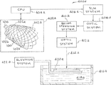
- FIG. 4A a first embodiment of an additive manufacturing system for making the smart stent of FIG. 1 is illustrated.
- This embodiment of the additive manufacturing system is designated generally by the reference numeral 400 a .
- This embodiment of the additive manufacturing system 400 a is a projection micro-stereolithography system.
- One version of the additive manufacturing system 400 a is a Large Area Projection Micro-Stereolithography (LAPuSL) system.
- LAPuSL Large Area Projection Micro-Stereolithography
- the additive manufacturing system 400 a produces the smart stent 100 .
- the structural elements of the additive manufacturing system 400 a are identified and described below.
- a three-dimensional model 402 a of the smart stent 100 is produced in a computer readable format.
- the model 402 a will be used by the additive manufacturing system 400 a to produce the stent 100 .
- the three-dimensional model 402 a of the stent 100 can be produced by 3-D CAD system.
- the three-dimensional model 402 a is sent to the CPU 404 a .
- the three-dimensional model is digitally sliced into layers by the CPU 404 a .
- the layers are sent to the SLM system 406 a and subsequently thru 408 a , 410 a , and 412 a to be projected 414 a to their appropriate locations on the moveable substrate 420 a.
- the layers are sent from the CPU 404 a to the SLM system 406 a .
- the layers are sent from the SLM system 406 a to the Optics system 408 a .
- the layers are sent from the Optics system 408 a to the Beam directing optics 410 a .
- the layers are sent from the Beam directing optics 410 a to the Optics system 412 a .
- the Optics system 412 a produces a Projected image 414 a into the Bath 418 a in the Reservoir 416 a .
- the first layer is produced on the substrate 420 a.
- the Projected image 414 a is an image beam that is directed onto the build plane to cure the curable monomer material of the Bath 418 a in the Reservoir 416 a and produce individual layers of the stent 100 .
- the elevator system 422 a sequentially lowers the layers into the curable monomer bath 418 a to allow a fresh layer of curable monomer material to coat the previous layer. The steps for all slices are repeated to complete the stent 100 .
- FIG. 4B another embodiment of an additive manufacturing system for making the smart stent 100 of FIG. 1 is illustrated.
- This embodiment of the additive manufacturing system is designated generally by the reference numeral 400 b .
- the additive manufacturing system 400 b produces the smart stent 100 .
- the additive manufacturing system 400 b uses state of the art 3-D printing technology to produce the smart stent 100 . Initially, a three-dimensional model of the smart stent 100 is produced in a computer readable format. The model is used by the additive manufacturing system 400 b to control the components of the 3-D printing system. The additive manufacturing system 400 b uses two head disposition printing to build the smart stent 100 on a substrate 408 b . The system 400 a uses one head 402 a for producing the web 104 and the other head 404 b for depositing the MEMS 102 ( a,b,c,d ) in the web 104 . The computer controller 410 b provides instructions for the 3D printing.
- one of the print heads 402 b obtains web material from a web material supply source 406 b .
- the print head 402 b uses the web material to print the web 104 .
- the other of the print head 404 b obtains MEMS devices 102 ( a,b,c,d ) from a supply source 408 b .
- the print head 404 b deposits the MEMS devices 102 ( a,b,c,d ) in the web 104 .
- the smart stent 100 is printed one layer at a time wherein each layer includes the predetermined portions of the web 104 and the MEMS devices 102 ( a,b,c,d ) as dictated by the three-dimensional model of the smart stent 100 .
- the layers are built on the substrate 408 b.
- FIG. 5 an illustrative view show another embodiment of Applicants' apparatus, systems, and methods. This embodiment is identified generally by the reference numeral 500 .
- the components of Applicants' smart stent apparatus, systems, and methods 500 shown in FIG. 5 are listed below.
- the smart stent 506 is shown implanted in a vascular bed 504 .
- the smart stent 506 functions by measuring fluid flow at localized areas within the stent, processing information through an integrated circuit (comparing the data to model simulations of flow perturbation), and selectively sending power to the mechanically controllable surface which results in localized geometric changes.
- the smart stent 506 transmits data to the telemetry module 502 that controls the operation of the smart stent 506 and analyzes the data.
- the telemetry module 502 compares the data to model simulations and selectively sends power to MEMS units that mechanically control the stent web and provide localized geometric changes in the stent web to correct for changes in flow due to plaque buildup.
- the telemetry module 502 can provide “periodic” or “on demand” reports.
- the smart stent 506 identifies and attenuates regions of low shear stress in the lumen of a stented blood vessel through an integrated, distributed network of flow sensors, a custom signal processing unit, power supply and telemetry into the shape memory polymer stent.
- the distributed network of flow sensors maps the hemodynamic flow with the stent. This data is sent to the processing unit and analyzed. If a shear stress threshold is met, computational fluid simulations determine the location and magnitude of stent actuation to decrease the area of low shear stress.
- the stent device operates as an autonomous closed loop system. The incorporation of telemetry allows for periodic or on demand data reports of stent health, flow data, and actuation and issues logs.
- Applicants' apparatus, systems, and methods is used in conjunction with current percutaneous interventional techniques to treat symptomatic atherosclerotic vascular disease in the coronary arteries, cerebral vasculature, and peripheral vasculature.
- Applicants' apparatus, systems, and methods invention can also be used to treat vascular aneurysms, coarctation, or other narrowings or dilations.
- Applicants' apparatus, systems, and methods can also be used in the pulmonary vasculature in pulmonary arterial hypertension, combined post- and pre-capillary pulmonary hypertension, chronic thromboembolic pulmonary hypertension as well as in the pulmonary and systemic venous and lymphatic systems.
- Applicants' apparatus, systems, and methods can also be used in any other area where a stent has been used, such as the heart or extra-vascular spaces, such as the airways.
- Applicants' apparatus, systems, and methods can also be used as a preventative device by endovascular implantation in the arterial, venous, or olymphatic system to prevent the development of atherosclerosis, aneurysm formation, or vessel/lymphatic narrowing.
Landscapes
- Health & Medical Sciences (AREA)
- Life Sciences & Earth Sciences (AREA)
- Public Health (AREA)
- Veterinary Medicine (AREA)
- Heart & Thoracic Surgery (AREA)
- Animal Behavior & Ethology (AREA)
- General Health & Medical Sciences (AREA)
- Engineering & Computer Science (AREA)
- Vascular Medicine (AREA)
- Biomedical Technology (AREA)
- Surgery (AREA)
- Biophysics (AREA)
- Physics & Mathematics (AREA)
- Pathology (AREA)
- Medical Informatics (AREA)
- Molecular Biology (AREA)
- Transplantation (AREA)
- Epidemiology (AREA)
- Cardiology (AREA)
- Oral & Maxillofacial Surgery (AREA)
- Chemical & Material Sciences (AREA)
- Manufacturing & Machinery (AREA)
- Materials Engineering (AREA)
- Pulmonology (AREA)
- Gastroenterology & Hepatology (AREA)
- Inorganic Chemistry (AREA)
- Hematology (AREA)
- Physiology (AREA)
- Prostheses (AREA)
Abstract
Description
“A device that monitors pressure in the surrounding area, as well as blood flow and temperature, would provide clinicians with a method for monitoring PADP, and therefore PCWP, and would provide information regarding how well the stent is faring in the implanted environment. Fully wireless operation as well as integration with the stent is crucial for such a device monitoring device. Current wireless cardiac pressure sensor devices require either a clinical visit or manual interrogation of the device using an external transmitter and receiver. This limits the overall effectiveness of the system by relying on the patient or a clinician to initiate collection of diagnostic data.”
“What is needed therefore is a completely wireless implantable system implanted in the pulmonary artery and having fully wireless capability, in terms of both telemetry and powering, through the chest wall to record cardiac diagnostics at fixed intervals without manual intervention.”
-
- 100—Adaptive Shear Responsive Endovascular Implant (smart stent),
- 102 a, 102 b, 102 c, and 102 d-Devices incorporate into the
smart stent 100 during AM manufacturing, - 104—Stent lattice, and
- 106—Control System (Brain).
-
- 200 a-Initial view of smart stent in an artery,
- 200 b-View of smart stent detecting turbulent flow in artery,
- 200 c-View of smart stent with corrected stent shape,
- 202 a-Flow sensors,
- 202 b-Heaters,
- 204—Stent body,
- 206—Control system (Brain),
- 208—Flow direction,
- 210—Normal flow, and
- 212—Turbulent flow area.
-
- 300 a-Initial view of smart stent showing normal flow,
- 300 b-View of smart stent detecting turbulent flow,
- 300 c-View of smart stent with corrected stent shape,
- 302 a-Flow sensors,
- 302 b-Heaters,
- 304—Stent body,
- 308—Flow direction,
- 310—Normal flow,
- 312—Turbulent flow area, and
- 314—Pillars (the pillars represent changes in the physical structure).
-
- Reference numeral 400 a-Additive manufacturing system.
- Reference numeral 402 a-3-D computer generated model of
stent 100. - Reference numeral 404 a-CPU.
-
Reference numeral 406 a-SLM system. - Reference numeral 408 a-Optics system.
- Reference numeral 410 a-Beam directing optics.
-
Reference numeral 412 a-Optics system. - Reference numeral 414 a-Projected image.
- Reference numeral 416 a-Reservoir.
- Reference numeral 418 a-Bath.
- Reference numeral 420 a-Substrate.
- Reference numeral 422 a-Elevator system.
-
- 502—telemetry,
- 504—vascular bed, and
- 506—smart stent,
- 508—receiver, and
- 510—signal.
Claims (29)
Priority Applications (3)
| Application Number | Priority Date | Filing Date | Title |
|---|---|---|---|
| US16/251,624 US11083604B2 (en) | 2019-01-18 | 2019-01-18 | Preventing stent failure using adaptive shear responsive endovascular implant |
| PCT/US2020/013952 WO2020150525A1 (en) | 2019-01-18 | 2020-01-16 | Stent of shape memory material and method |
| US17/374,616 US11918495B2 (en) | 2019-01-18 | 2021-07-13 | Preventing stent failure using adaptive shear responsive endovascular implant |
Applications Claiming Priority (1)
| Application Number | Priority Date | Filing Date | Title |
|---|---|---|---|
| US16/251,624 US11083604B2 (en) | 2019-01-18 | 2019-01-18 | Preventing stent failure using adaptive shear responsive endovascular implant |
Related Child Applications (1)
| Application Number | Title | Priority Date | Filing Date |
|---|---|---|---|
| US17/374,616 Division US11918495B2 (en) | 2019-01-18 | 2021-07-13 | Preventing stent failure using adaptive shear responsive endovascular implant |
Publications (2)
| Publication Number | Publication Date |
|---|---|
| US20200229952A1 US20200229952A1 (en) | 2020-07-23 |
| US11083604B2 true US11083604B2 (en) | 2021-08-10 |
Family
ID=71608538
Family Applications (2)
| Application Number | Title | Priority Date | Filing Date |
|---|---|---|---|
| US16/251,624 Active 2039-09-15 US11083604B2 (en) | 2019-01-18 | 2019-01-18 | Preventing stent failure using adaptive shear responsive endovascular implant |
| US17/374,616 Active 2039-11-24 US11918495B2 (en) | 2019-01-18 | 2021-07-13 | Preventing stent failure using adaptive shear responsive endovascular implant |
Family Applications After (1)
| Application Number | Title | Priority Date | Filing Date |
|---|---|---|---|
| US17/374,616 Active 2039-11-24 US11918495B2 (en) | 2019-01-18 | 2021-07-13 | Preventing stent failure using adaptive shear responsive endovascular implant |
Country Status (2)
| Country | Link |
|---|---|
| US (2) | US11083604B2 (en) |
| WO (1) | WO2020150525A1 (en) |
Cited By (1)
| Publication number | Priority date | Publication date | Assignee | Title |
|---|---|---|---|---|
| US11918495B2 (en) | 2019-01-18 | 2024-03-05 | Lawrence Livermore National Security, Inc. | Preventing stent failure using adaptive shear responsive endovascular implant |
Families Citing this family (4)
| Publication number | Priority date | Publication date | Assignee | Title |
|---|---|---|---|---|
| EP3964123A1 (en) * | 2020-09-06 | 2022-03-09 | Cerebrolytics Inc | A brain-computer interface |
| WO2024002764A1 (en) * | 2022-06-30 | 2024-01-04 | Koninklijke Philips N.V. | Local manufacturing of a medical stent based on a computational modeled outcome prediction |
| CN117507367B (en) * | 2024-01-08 | 2024-04-05 | 北京阿迈特医疗器械有限公司 | Support printing method and device with mark points |
| WO2026024537A1 (en) * | 2024-07-26 | 2026-01-29 | Covidien Lp | Configurations for endovascular therapy device |
Citations (16)
| Publication number | Priority date | Publication date | Assignee | Title |
|---|---|---|---|---|
| US5133732A (en) * | 1987-10-19 | 1992-07-28 | Medtronic, Inc. | Intravascular stent |
| US5135536A (en) * | 1991-02-05 | 1992-08-04 | Cordis Corporation | Endovascular stent and method |
| US5843120A (en) * | 1994-03-17 | 1998-12-01 | Medinol Ltd. | Flexible-expandable stent |
| US5935162A (en) * | 1998-03-16 | 1999-08-10 | Medtronic, Inc. | Wire-tubular hybrid stent |
| US5980552A (en) | 1994-03-17 | 1999-11-09 | Medinol Ltd. | Articulated stent |
| WO2000010623A1 (en) | 1998-08-25 | 2000-03-02 | Tricardia, L.L.C. | An implantable device for promoting repair of a body lumen |
| WO2001019239A1 (en) | 1999-09-17 | 2001-03-22 | Endoluminal Therapeutics, Inc. | Sensing, interrogating, storing, telemetering and responding medical implants |
| US6790227B2 (en) * | 2001-03-01 | 2004-09-14 | Cordis Corporation | Flexible stent |
| US20050080346A1 (en) | 2002-12-16 | 2005-04-14 | The Regents Of The University Of Michigan | Antenna stent device for wireless, intraluminal monitoring |
| US20050277839A1 (en) | 2004-06-10 | 2005-12-15 | Honeywell International, Inc. | Wireless flow measurement in arterial stent |
| US20060129050A1 (en) | 2004-11-15 | 2006-06-15 | Martinson James B | Instrumented implantable stents, vascular grafts and other medical devices |
| US8500794B2 (en) | 2007-08-02 | 2013-08-06 | Flexible Stenting Solutions, Inc. | Flexible stent |
| WO2014144070A1 (en) | 2013-03-15 | 2014-09-18 | Hunter William L | Stent monitoring assembly and method of use thereof |
| US20150164372A1 (en) | 2012-07-20 | 2015-06-18 | Amin Katouzian | Intelligent implanted health sensing device and assembly |
| US9662021B2 (en) | 2009-01-12 | 2017-05-30 | Purdue Research Foundation | Miniature stent-based implantable wireless monitoring devices |
| US20190183665A1 (en) * | 2016-08-26 | 2019-06-20 | The Catholic University Of Korea Industry-Academic Cooperation Foundation | Stent Using Wireless Transmitted Power and External Operating Apparatus Thereof |
Family Cites Families (6)
| Publication number | Priority date | Publication date | Assignee | Title |
|---|---|---|---|---|
| US20140163664A1 (en) * | 2006-11-21 | 2014-06-12 | David S. Goldsmith | Integrated system for the ballistic and nonballistic infixion and retrieval of implants with or without drug targeting |
| WO2009042671A1 (en) * | 2007-09-24 | 2009-04-02 | The Board Of Trustees Of The University Of Illinois | Three-dimensional microfabricated bioreactors with embedded capillary network |
| EP4449979A3 (en) * | 2014-06-25 | 2025-05-21 | Canary Medical Switzerland AG | Devices, systems and methods for using and monitoring implants |
| WO2016176444A1 (en) * | 2015-04-29 | 2016-11-03 | Northwestern University | 3d printing of biomedical implants |
| WO2017004483A1 (en) * | 2015-07-02 | 2017-01-05 | Mirus Llc | Medical devices with integrated sensors and method of production |
| US11083604B2 (en) | 2019-01-18 | 2021-08-10 | Lawrence Livermore National Security, Llc | Preventing stent failure using adaptive shear responsive endovascular implant |
-
2019
- 2019-01-18 US US16/251,624 patent/US11083604B2/en active Active
-
2020
- 2020-01-16 WO PCT/US2020/013952 patent/WO2020150525A1/en not_active Ceased
-
2021
- 2021-07-13 US US17/374,616 patent/US11918495B2/en active Active
Patent Citations (18)
| Publication number | Priority date | Publication date | Assignee | Title |
|---|---|---|---|---|
| US5133732A (en) * | 1987-10-19 | 1992-07-28 | Medtronic, Inc. | Intravascular stent |
| US5135536A (en) * | 1991-02-05 | 1992-08-04 | Cordis Corporation | Endovascular stent and method |
| US5843120A (en) * | 1994-03-17 | 1998-12-01 | Medinol Ltd. | Flexible-expandable stent |
| US5980552A (en) | 1994-03-17 | 1999-11-09 | Medinol Ltd. | Articulated stent |
| US5935162A (en) * | 1998-03-16 | 1999-08-10 | Medtronic, Inc. | Wire-tubular hybrid stent |
| WO2000010623A1 (en) | 1998-08-25 | 2000-03-02 | Tricardia, L.L.C. | An implantable device for promoting repair of a body lumen |
| WO2001019239A1 (en) | 1999-09-17 | 2001-03-22 | Endoluminal Therapeutics, Inc. | Sensing, interrogating, storing, telemetering and responding medical implants |
| US6790227B2 (en) * | 2001-03-01 | 2004-09-14 | Cordis Corporation | Flexible stent |
| US20050080346A1 (en) | 2002-12-16 | 2005-04-14 | The Regents Of The University Of Michigan | Antenna stent device for wireless, intraluminal monitoring |
| US20050277839A1 (en) | 2004-06-10 | 2005-12-15 | Honeywell International, Inc. | Wireless flow measurement in arterial stent |
| US20060129050A1 (en) | 2004-11-15 | 2006-06-15 | Martinson James B | Instrumented implantable stents, vascular grafts and other medical devices |
| US8308794B2 (en) | 2004-11-15 | 2012-11-13 | IZEK Technologies, Inc. | Instrumented implantable stents, vascular grafts and other medical devices |
| US8784475B2 (en) | 2004-11-15 | 2014-07-22 | Izex Technologies, Inc. | Instrumented implantable stents, vascular grafts and other medical devices |
| US8500794B2 (en) | 2007-08-02 | 2013-08-06 | Flexible Stenting Solutions, Inc. | Flexible stent |
| US9662021B2 (en) | 2009-01-12 | 2017-05-30 | Purdue Research Foundation | Miniature stent-based implantable wireless monitoring devices |
| US20150164372A1 (en) | 2012-07-20 | 2015-06-18 | Amin Katouzian | Intelligent implanted health sensing device and assembly |
| WO2014144070A1 (en) | 2013-03-15 | 2014-09-18 | Hunter William L | Stent monitoring assembly and method of use thereof |
| US20190183665A1 (en) * | 2016-08-26 | 2019-06-20 | The Catholic University Of Korea Industry-Academic Cooperation Foundation | Stent Using Wireless Transmitted Power and External Operating Apparatus Thereof |
Non-Patent Citations (4)
| Title |
|---|
| International Search Report and Written Opinion for PCT/US2020/013952 corresponding to U.S. Appl. No. 16/251,624, 9 pages. (dated Jun. 4, 2020). |
| Leopold, "Pro-Healing Endothelial Progenitor Cell Capture Stents: Do the Cells Captured Explain the Clinical Outcomes?," Circ. Cardiovasc. Interv, vol. 6, No. 5, 2013, pp. 494-495. |
| Randles et al., "Computational Fluid Dynamics and Additive Manufacturing to Diagnose and Treat Cardiovascular Disease," Trends Bioechnol., vol. 35, No. 11, 2017, pp. 1049-1061. |
| Shikida et al., "Fabrication of a stent-type thermal flow sensor for measuring nasal respiration," J. of Micromech. Microeng, 20, 2020, 8 pp., (Apr. 26, 2010). |
Cited By (1)
| Publication number | Priority date | Publication date | Assignee | Title |
|---|---|---|---|---|
| US11918495B2 (en) | 2019-01-18 | 2024-03-05 | Lawrence Livermore National Security, Inc. | Preventing stent failure using adaptive shear responsive endovascular implant |
Also Published As
| Publication number | Publication date |
|---|---|
| US20210338463A1 (en) | 2021-11-04 |
| US11918495B2 (en) | 2024-03-05 |
| US20200229952A1 (en) | 2020-07-23 |
| WO2020150525A1 (en) | 2020-07-23 |
Similar Documents
| Publication | Publication Date | Title |
|---|---|---|
| US11918495B2 (en) | Preventing stent failure using adaptive shear responsive endovascular implant | |
| US20240398338A1 (en) | Devices, systems and methods for using and monitoring heart valves | |
| JP7815325B2 (en) | Stent monitoring assembly and method of use - Patents.com | |
| CA2737753C (en) | Expandable slide and lock stent | |
| Hatami et al. | Exploring the potential of 3D and 4D printing in advancing stent manufacturing for cardiovascular diseases | |
| WO2008006003A2 (en) | Methods and systems for monitoring an endoprosthetic implant | |
| US8478378B2 (en) | Devices, systems and methods to detect endothelialization of implantable medical devices | |
| TW201927234A (en) | Devices and methods for atrial mapping, sensing and treating cardiac arrhythmia | |
| US20140088698A1 (en) | Patient-specific intraluminal implants | |
| EP2988704B1 (en) | Expandable deformable slide and lock stent | |
| Yasmin et al. | Application of additive manufacturing in the development of polymeric bioresorbable cardiovascular stents: a review | |
| US20230098512A1 (en) | Ostial stenting under vision | |
| Wang et al. | Fluid-structure interaction based study on the physiological factors affecting the behaviors of stented and non-stented thoracic aortic aneurysms | |
| AU2013204977B2 (en) | Expandable slide and lock stent | |
| CN120417832A (en) | Transcatheter heart valve with deformable inductor for dual wireless pressure monitoring | |
| KR102520875B1 (en) | Recliner having health care performance | |
| Farhan Khan et al. | A novel approach to design lesion-specific stents for minimum recoil | |
| Nasiri Sadr et al. | Evaluation of Energy Harvesting from Different Sections of the Aortic Artery with Several Energy Harvester Materials | |
| EP4687154A1 (en) | A computer-implemented method for training at least one deployment model, a computer program, a non-transitory computer-readable medium, a trained machine-learning model, a computer implemented method for predicting a deployment of a heart valve prosthesis, a medical apparatus, and a method for deploying a heart valve prosthesis | |
| Aggarwal et al. | Heterogeneity and multi-scale modelling | |
| WO2026027539A1 (en) | A computer-implemented method for training at least one deployment model, a computer program, a non-transitory computer-readable medium, a trained machine-learning model, a computer implemented method for predicting a deployment of a heart valve prosthesis, a medical apparatus, and a method for deploying a heart valve prosthesis | |
| WO2025054142A1 (en) | Variable force stent design | |
| Hoseini | Progettazione e sviluppo di dispositivi in Nitinol per applicazioni attuative e biomediche | |
| Pastaa et al. | Simulation of lvot obstruction in transcatheter mitral valve-in-ring replacement | |
| van Bakel et al. | Novel Understanding on Thoracic |
Legal Events
| Date | Code | Title | Description |
|---|---|---|---|
| AS | Assignment |
Owner name: LAWRENCE LIVERMORE NATIONAL SECURITY, LLC, CALIFORNIA Free format text: ASSIGNMENT OF ASSIGNORS INTEREST;ASSIGNOR:MUKERJEE, ERIK V.;REEL/FRAME:048058/0785 Effective date: 20190116 |
|
| FEPP | Fee payment procedure |
Free format text: ENTITY STATUS SET TO UNDISCOUNTED (ORIGINAL EVENT CODE: BIG.); ENTITY STATUS OF PATENT OWNER: LARGE ENTITY |
|
| AS | Assignment |
Owner name: U.S. DEPARTMENT OF ENERGY, DISTRICT OF COLUMBIA Free format text: CONFIRMATORY LICENSE;ASSIGNOR:LAWRENCE LIVERMORE NATIONAL SECURITY, LLC;REEL/FRAME:048440/0367 Effective date: 20190221 |
|
| AS | Assignment |
Owner name: THE BRIGHAM AND WOMEN'S HOSPITAL, INC., MASSACHUSETTS Free format text: ASSIGNMENT OF ASSIGNORS INTEREST;ASSIGNOR:LEOPOLD, JANE A.;REEL/FRAME:048514/0650 Effective date: 20190213 |
|
| AS | Assignment |
Owner name: DUKE UNIVERSITY, NORTH CAROLINA Free format text: ASSIGNMENT OF ASSIGNORS INTEREST;ASSIGNOR:RANDLES, AMANDA;REEL/FRAME:048900/0676 Effective date: 20190311 |
|
| STPP | Information on status: patent application and granting procedure in general |
Free format text: NON FINAL ACTION MAILED |
|
| STPP | Information on status: patent application and granting procedure in general |
Free format text: RESPONSE TO NON-FINAL OFFICE ACTION ENTERED AND FORWARDED TO EXAMINER |
|
| STPP | Information on status: patent application and granting procedure in general |
Free format text: FINAL REJECTION MAILED |
|
| STPP | Information on status: patent application and granting procedure in general |
Free format text: DOCKETED NEW CASE - READY FOR EXAMINATION |
|
| STPP | Information on status: patent application and granting procedure in general |
Free format text: NOTICE OF ALLOWANCE MAILED -- APPLICATION RECEIVED IN OFFICE OF PUBLICATIONS |
|
| STPP | Information on status: patent application and granting procedure in general |
Free format text: PUBLICATIONS -- ISSUE FEE PAYMENT VERIFIED |
|
| STCF | Information on status: patent grant |
Free format text: PATENTED CASE |
|
| MAFP | Maintenance fee payment |
Free format text: PAYMENT OF MAINTENANCE FEE, 4TH YEAR, LARGE ENTITY (ORIGINAL EVENT CODE: M1551); ENTITY STATUS OF PATENT OWNER: LARGE ENTITY Year of fee payment: 4 |