US11079445B2 - Terminal state measurement device for coaxial cable - Google Patents
Terminal state measurement device for coaxial cable Download PDFInfo
- Publication number
- US11079445B2 US11079445B2 US16/558,475 US201916558475A US11079445B2 US 11079445 B2 US11079445 B2 US 11079445B2 US 201916558475 A US201916558475 A US 201916558475A US 11079445 B2 US11079445 B2 US 11079445B2
- Authority
- US
- United States
- Prior art keywords
- conductor terminal
- inner conductor
- outer conductor
- terminal
- coaxial cable
- Prior art date
- Legal status (The legal status is an assumption and is not a legal conclusion. Google has not performed a legal analysis and makes no representation as to the accuracy of the status listed.)
- Active, expires
Links
Images


Classifications
-
- G—PHYSICS
- G01—MEASURING; TESTING
- G01R—MEASURING ELECTRIC VARIABLES; MEASURING MAGNETIC VARIABLES
- G01R31/00—Arrangements for testing electric properties; Arrangements for locating electric faults; Arrangements for electrical testing characterised by what is being tested not provided for elsewhere
- G01R31/50—Testing of electric apparatus, lines, cables or components for short-circuits, continuity, leakage current or incorrect line connections
- G01R31/66—Testing of connections, e.g. of plugs or non-disconnectable joints
- G01R31/68—Testing of releasable connections, e.g. of terminals mounted on a printed circuit board
- G01R31/69—Testing of releasable connections, e.g. of terminals mounted on a printed circuit board of terminals at the end of a cable or a wire harness; of plugs; of sockets, e.g. wall sockets or power sockets in appliances
-
- G—PHYSICS
- G01—MEASURING; TESTING
- G01R—MEASURING ELECTRIC VARIABLES; MEASURING MAGNETIC VARIABLES
- G01R31/00—Arrangements for testing electric properties; Arrangements for locating electric faults; Arrangements for electrical testing characterised by what is being tested not provided for elsewhere
- G01R31/12—Testing dielectric strength or breakdown voltage ; Testing or monitoring effectiveness or level of insulation, e.g. of a cable or of an apparatus, for example using partial discharge measurements; Electrostatic testing
Definitions
- the present invention relates to a terminal state measurement device for a coaxial cable which is configured to measure a mutual relationship between an inner conductor terminal connected to an inner conductor of a coaxial cable and an outer conductor terminal connected to an outer conductor of the coaxial cable when the inner conductor terminal and the outer conductor terminal are combined and fixed.
- an inner conductor terminal connected to an inner conductor (also referred to as a “signal conductor”) of a coaxial cable and an outer conductor terminal connected to an outer conductor (also referred to as “shield conductor”) of the coaxial cable are combined and fixed to form a connector terminal, for example, the following is performed. That is, the inner conductor terminal is connected and fixed in advance to a tip end of the inner conductor of an end portion of the coaxial cable. Next, the inner conductor terminal is inserted into a substantially cylindrical inside of the outer conductor terminal from rear. In this state, the outer conductor terminal is connected and fixed to the outer conductor of the coaxial cable (see Patent Document JP-A-2003-297493).
- the inner conductor terminal is inserted into an inside of a dielectric (solid component) housed inside the outer conductor terminal. Therefore, a position of the inner conductor terminal with respect to the outer conductor terminal can be properly determined by the dielectric.
- the outer conductor terminal and the inner conductor terminal may contact each other and become defective depending on an assembly state. Therefore, a quality determination must be separately performed by inspecting a conduction state between the outer conductor terminal and the inner conductor terminal, so that there is also a problem that improvement in productivity is limited due to a process of manually moving the coaxial cable to a device for conduction inspection.
- the present invention has been made in view of the above circumstances, and an aspect of the present invention is to provide a terminal state measurement device for a coaxial cable which can efficiently and easily manage mutual positions of an inner conductor terminal connected to an inner conductor of a coaxial cable and an outer conductor terminal connected to an outer conductor of the coaxial cable and can efficiently and easily manage mutual insulation between the inner conductor terminal and the outer conductor terminal.
- a terminal state measurement device for a coaxial cable is characterized by the following (1) to (3).
- a terminal state measurement device for a coaxial cable comprising:
- a conductive cylindrical body which comes close to a front end edge of an outer conductor terminal held and fixed in advance from a front side to bring a front end face of the conductive cylindrical body in the axial direction into contact with the front end edge when the outer conductor terminal is connected and fixed to an outer conductor of an end portion of a coaxial cable;
- a conduction measurement element which is housed in an inner periphery of the conductive cylindrical body via an insulating material, which is displaceable with respect to the conductive cylindrical body in an axial direction, and which contacts a front end of an inner conductor terminal connected and fixed to an inner conductor of the end portion of the coaxial cable from the front side to displace in the axial direction in accordance with an insertion position of the inner conductor terminal when the inner conductor terminal is inserted into an inside of the outer conductor terminal from a rear side;
- a displacement measurement device which is configured to measure a position of the front end of the inner conductor terminal based on a displacement amount of the conduction measurement element in the axial direction;
- an insulation determination unit which is configured to determine an insulation quality between the inner conductor terminal and the outer conductor terminal based on a conduction state of the conduction measurement element and the conductive cylindrical body.
- the insulation determination unit determines the insulation quality between the inner conductor terminal and the outer conductor terminal at any timing from a start of contacting of the front end of the inner conductor terminal with the conduction measurement element to an end of the contacting.
- the insulation determination unit determines the insulation quality between the inner conductor terminal and the outer conductor terminal at a timing when the displacement measurement device detects that the front end of the inner conductor terminal is at a proper position.
- the front end of the inner conductor terminal can be properly positioned with respect to the outer conductor terminal in the axial direction based on the displacement amount of the conduction measurement element which contacts the front end of the inner conductor terminal.
- the displacement amount is detected by the displacement measurement device.
- the conduction measurement element is in contact with the inner conductor terminal and the conductive cylindrical body is in contact with the outer conductor terminal. Therefore, the insulation quality between the inner conductor terminal and the outer conductor terminal can be determined by determining whether the conduction measurement element and the conductive cylindrical body are electrically connected to each other.
- both the mutual positioning of the inner conductor terminal and the outer conductor terminal and the insulation determination between the inner conductor terminal and the outer conductor terminal can be performed using one displacement measurement device. That is, it is not necessary to perform the insulation inspection as a separate process later. Therefore, mutual positions of the inner conductor terminal and the outer conductor terminal and the mutual insulation between the inner conductor terminal and the outer conductor terminal can be managed efficiently and easily, so that productivity can be improved.
- the insulation quality of the outer conductor terminal and the inner conductor terminal is determined at any timing from the start of contacting of the front end of the inner conductor terminal with the conduction measurement element to the end of the contacting. Therefore, rapid processing can be performed, so that productivity can be improved.
- the insulation quality of the outer conductor terminal and the inner conductor terminal is determined at the timing when the inner conductor terminal is properly positioned with respect to the outer conductor terminal. Therefore, rapid processing can be performed, which facilitates elimination of defective products. Connection processing of the outer conductor terminal immediately after can also be efficiently performed only for products which are determined as non-defective products, so that productivity can be improved.
- the mutual positions of the inner conductor terminal connected to the inner conductor of the coaxial cable and the outer conductor terminal connected to the outer conductor of the coaxial cable and the mutual insulation between the inner conductor terminal and the outer conductor terminal can be managed efficiently and easily, so that productivity can be improved.
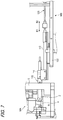
- FIG. 1 is a perspective view illustrating an overall configuration of a coaxial cable end processing apparatus in which a measurement device which is a terminal state measurement device for a coaxial cable according to an embodiment of the present invention is combined with a terminal crimping device.
- FIG. 2 is a perspective view illustrating configurations of an inner conductor terminal connected and fixed in advance to an end portion of the coaxial cable and an outer conductor terminal to be connected and fixed to the end portion of the coaxial cable.
- FIG. 3 is a perspective view illustrating an overall configuration of the measurement device.
- FIG. 4 is a perspective view illustrating an appearance configuration of a measurement sensor unit of the measurement device.
- FIG. 5 is an enlarged side view of a processing step of the coaxial cable end processing apparatus, which illustrates a state where the outer conductor terminal is set on an anvil.
- FIG. 6 is an enlarged side view of a step next to the step in FIG. 5 , which illustrates a state where the outer conductor terminal set on the anvil is pushed by a crimper.
- FIG. 7 is a side view of a step next to the step in FIG. 6 , which illustrates a state where the measurement sensor unit is brought close to and brought into contact with a front end of the outer conductor terminal pushed by the crimper from a front side.
- FIG. 8 is an enlarged side view of a main part in FIG. 7 .
- FIG. 9 is an enlarged side view of a step next to the step in FIG. 8 , which illustrates a state where the inner conductor terminal which is connected and fixed in advance to the end portion of the coaxial cable is to be inserted into an inside of the outer conductor terminal from a rear side.
- FIG. 10 is a side cross sectional view of a step next to the step in FIG. 9 , which illustrates a state where the inner conductor terminal is inserted to a proper position inside the outer conductor terminal, and an enlarged view of a main part thereof.
- FIG. 11 is a side cross sectional view illustrating an example in which a defect determination is performed based on a detection result that the outer conductor terminal and the inner conductor terminal are in contact with each other and the two terminals are electrically connected to each other at the same timing as in FIG. 10 .
- FIG. 12 is an enlarged side view of a step next to the step in FIG. 9 , which illustrates a state when the outer conductor terminal is connected and fixed to the coaxial cable such that the measurement sensor unit is retracted.
- FIG. 13 is an external perspective view of an end processing unit of the finished coaxial cable obtained after the step in FIG. 12 is performed.
- FIG. 1 is a perspective view illustrating an overall configuration of a coaxial cable end processing apparatus M in which a measurement device MB which is a terminal state measurement device for a coaxial cable according to an embodiment is combined with a terminal crimping device MA.
- the coaxial cable end processing apparatus M combines the terminal crimping device MA and the measurement device (terminal state measurement device for a coaxial cable) MB.
- the terminal crimping device MA includes an anvil (lower mold) 1 and a crimper (upper mold) 2 .
- the terminal crimping device MA performs a necessary cutting process or crimping process on an object to be processed by lowering the crimper 2 on the fixed anvil 1 .
- the object to be processed is an outer conductor terminal 20 .
- FIG. 2 is a perspective view illustrating configurations of an inner conductor terminal 10 connected and fixed in advance to an end portion of an coaxial cable and the outer conductor terminal 20 .
- the outer conductor terminal 20 is the object to be processed which is to be connected and fixed to the end portion of the coaxial cable W by the coaxial cable end processing device M in FIG. 1 .
- the coaxial cable W is a coaxial electric wire including an inner conductor (signal conductor) Wa for signal transmission, an insulator (dielectric) Wb covering a periphery of the inner conductor Wa, an outer conductor (shield conductor) Wc which is a braided wire, an aluminum foil, or the like covering a periphery of the insulator Wb, and an insulating sheath (outer cover) Wd covering an outer periphery of the outer conductor Wc.
- the inner conductor terminal 10 and the outer conductor terminal 20 combine to form a coaxial connector.
- the inner conductor terminal 10 is connected and fixed to the inner conductor Wa of the coaxial cable W.
- the inner conductor terminal 10 is formed into a substantially cylindrical shape by press bending after a metal plate is punched out, which includes a cylindrical portion 11 on a front end side of the inner conductor terminal 10 and a crimping piece 12 on a rear end side of the inner conductor terminal 10 .
- the inner conductor terminal 10 includes a female terminal shape, and a male terminal on a mating connector side is inserted into the cylindrical portion 11 .
- the inner conductor terminal 10 is crimped and connected to a front end of the peeled and exposed inner conductor Wa of the end portion of the coaxial cable W by the crimping piece 12 .
- the inner conductor terminal 10 in FIG. 2 is illustrated as a state before the crimping process.
- the outer conductor terminal 20 is formed by press bending after the metal plate is punched out, which includes a cylindrical main body cylindrical portion 21 opened forward and backward on a front side part of the outer conductor terminal 20 and a crimping piece 22 on a rear side of the outer conductor terminal 20 .
- the outer conductor terminal 20 is crimped and connected to the pre-processed outer conductor Wc of the end portion of the coaxial cable W by the crimping piece 12 .
- the pre-processed outer conductor Wc of the end portion of the coaxial cable W is, for example, a portion subjected to a process of turning over the cylindrical outer conductor Wc having a predetermined length and covering the sheath as illustrated in FIG. 2 .
- the coaxial cable end processing apparatus M illustrated in FIG. 1 performs processing for connecting and fixing the outer conductor terminal 20 to the coaxial cable W after combining the inner conductor terminal 10 attached in advance to the end portion of the coaxial cable W with the outer conductor terminal 20 and performing alignment and predetermined inspection.
- the measurement device MB is used for positioning of the inner conductor terminal 10 with respect to the outer conductor terminal 20 and inspection of the insulation between the outer conductor terminal 20 and the inner conductor terminal 10 during the processing.
- the inner conductor terminal 10 connected and fixed to the front end of the inner conductor Wa of the end portion of the coaxial cable W is inserted into a substantially cylindrical inside of the outer conductor terminal 20 from rear.
- the outer conductor terminal 20 is connected and fixed to the outer conductor We of the end portion of the coaxial cable W.
- the measurement device MB is used to measure a relationship between the inner conductor terminal 10 and the outer conductor terminal 20 in the insertion step.
- a front side (arrow A 1 direction in FIG. 1 ) and a rear side (arrow A 2 direction in FIG. 1 ) is defined for the terminal crimping device MA with reference to the coaxial cable W.
- the inner conductor terminal 10 is attached to the front end of the coaxial cable W.
- the inner conductor terminal 10 is fed out forward (in the arrow A 1 direction) along an axis of the coaxial cable W from a horizontal direction and inserted into the inside of the outer conductor terminal 20 set on the anvil 1 from a rear side of the outer conductor terminal 20 when the inner conductor terminal 10 is assembled to the outer conductor terminal 20 .
- the outer conductor terminal 20 is set on the terminal crimping device MA such that a rear end side of the outer conductor terminal 20 is directed in a direction in which the inner conductor terminal 10 enters.
- the plurality of pressed outer conductor terminals 20 are connected in a chain shape by a carrier 30 , and are intermittently fed and moved on the anvil 1 in the horizontal direction orthogonal to a direction in which the inner conductor terminal 10 is fed out, that is, in a left-right direction.
- the inner conductor terminal 10 is fed out forward along the axis of the coaxial cable W.
- the axis, along which the inner conductor terminal 10 is fed out will be referred to as an operation axis N.
- the outer conductor terminal 20 to be operated is set on the anvil 1 along the operation axis N.
- the crimper 2 performs the cutting process or crimping process on the outer conductor terminal 20 set on the operation axis N.
- the terminal crimping device MA includes a vertical wall 5 in front of the direction in which the inner conductor terminal 10 is fed out, that is, in front of a position where the anvil 1 is disposed. A drive mechanism of the crimper 2 and the like are supported by the vertical wall 5 . Then, the measurement device MB, which is the terminal state measurement device of the coaxial cable according to the embodiment, is disposed in front of the terminal crimping device MA with the vertical wall 5 interposed therebetween.
- the measurement device MB is configured around a measurement sensor unit 110 .
- FIG. 3 is a perspective view illustrating an overall configuration of the measurement device MB.
- FIG. 4 is a perspective view illustrating an appearance configuration of the measurement sensor unit 110 of the measurement device MB.
- the measurement device MB will be described in detail with reference to FIGS. 3 and 4 .
- a directionality of the measurement device MB is determined based on an operation direction of the measurement device MB. That is, the measurement sensor unit 110 , which is finally position-controlled, has a rod shape, and is mounted with an axial direction of the measurement sensor unit 110 being horizontal. The measurement sensor unit 110 is moved in an upper-lower direction so as to be positioned, and is moved forward and rearward in the axial direction so as to be positioned. Therefore, a forward direction of the measurement sensor unit 110 is defined as a front side (arrow B 1 direction in FIG. 3 ) of the measurement device MB, and a rearward direction of the measurement sensor unit 110 is defined as a rear side (arrow B 2 direction in FIG. 3 ) of the measurement device MB.
- the front side and the rear side are determined with reference to the measurement device M and thus are opposite to the front side and the rear side (the arrow A 1 direction and the arrow A 2 direction in FIG. 1 ) of the terminal crimping device MA illustrated in FIG. 1 .
- the measurement device MB includes a base plate 150 as a base.
- a upper-lower movement mechanism 130 is provided at a front end portion (end portion in the arrow B 1 direction in FIG. 3 ) of the base plate 150 .
- the upper-lower movement mechanism 130 is configured to move an upper-lower movement table 132 in the upper-lower direction by an upper-lower movement actuator 131 to position the upper-lower movement table 132 .
- a front-rear movement mechanism 120 is provided on the upper-lower movement table 132 .
- the front-rear movement mechanism 120 moves a front-rear movement table 122 in a front-rear direction (the arrow B 1 direction and the arrow B 2 direction in FIG. 3 ) by a front-rear movement actuator 121 to position the front-rear movement table 122 .
- the front-rear movement actuator 121 is disposed on a rear end side (end portion side in the arrow B 2 direction in FIG. 3 ) of the upper-lower movement table 132
- the front-rear movement table 122 is disposed on a front end side (end portion side in the arrow B 1 direction in FIG. 3 ) of the upper-lower movement table 132 .
- the measurement sensor unit 110 is provided on the front-rear movement table 122 via a holder 111 .
- a measurement result display unit 140 which is configured to display measurement data of the measurement sensor unit 110 , is provided on a rear end side of the front-rear movement table 122 .
- FIG. 10 is used as a reference drawing.
- FIG. 10 illustrates details of the configuration of the measurement sensor unit 110 in cross section.
- the measurement sensor unit 110 corresponds to a displacement measurement device, and uses a resin pipe 105 as a central support member.
- a measurement rod 101 is housed inside the resin pipe 105 so as to be slidable in the axial direction, and a conduction measurement element 100 made of a conductive material which is metal or the like is provided at a front end of the measurement rod 101 .
- a cylindrical metal bush (metal cylindrical body) 103 is fixed to a front end of the resin pipe 105 , and the conductive measurement element 100 is housed in the metal bush 103 via an insulating material ring 102 so as to be displaceable in the axial direction.
- the measurement element 100 is displaced integrally with the measurement rod 101 in the axial direction, so that the measurement sensor unit 110 measures a displacement amount of the measurement element 100 via the measurement rod 101 .
- the metal bush 103 comes close to a front end edge 21 a of the outer conductor terminal 20 held and fixed in advance on the anvil 1 from the front side to bring the front end face 103 a of the metal bush 103 in the axial direction into contact with the front end edge 21 a.
- the measurement device 100 When the inner conductor terminal 10 is inserted into the inside of the outer conductor terminal 20 from the rear side, the measurement device 100 contacts a front end 11 a of the inner conductor terminal 10 from the front side to displace in the axial direction in accordance with an insertion position of the inner conductor terminal 10 .
- the measurement sensor unit 110 is configured to measure a position of the front end of the inner conductor terminal 10 based on the displacement amount of the measurement element 100 in the axial direction. When the displacement amount reaches a predetermined value, a position of a displacement measurement object (in this case, the inner conductor terminal 10 ) in the axial direction can be determined by restricting a movement of the measurement element 100 or restricting a movement of the displacement measurement object which moves the measurement element 100 by pushing.
- the insertion of the inner conductor terminal 10 is stopped at a timing when the front end 11 a of the measurement element 100 is positioned forward (in the arrow B 1 direction) from the front end edge 21 a of the outer conductor terminal 20 by a dimension S (for example, 0.25 mm) with reference to a position of the front end edge 21 a of the outer conductor terminal 20 in contact with the front end surface 103 a of the metal bush 103 .
- a dimension S for example, 0.25 mm
- the measurement element 100 and the metal bush 103 which are used as described above, both serve as an electrical detector. That is, a first conductive member (electric wire, metal plate, or the like) 106 is electrically connected to the measurement element 100 via a screw 107 . A second conductive member (electric wire, metal plate, or the like) 108 is electrically connected to the metal bush 103 via a screw 109 . The first conductive member 106 and the second conductive member 108 are electrically connected to the insulation determination unit 200 . The insulation determination unit 200 is configured to detect whether the first conductive member 106 and the second conductive member 108 are electrically connected to each other.
- This determination may be performed at any timing when the measurement element 100 is in contact with the inner conductor terminal 10 and the metal bush 103 is in contact with the outer conductor terminal 20 . However, this determination may be simultaneously performed at a timing when the measurement sensor unit 110 positions the inner conductor terminal 10 (that is, a timing when it is detected that the front end of the inner conductor terminal is at a proper position).
- FIG. 5 is an enlarged side view of a processing step of the coaxial cable end processing apparatus M, which illustrates a state where the outer conductor terminal 20 is set on the anvil 1 .
- FIG. 6 is an enlarged side view of a step next to the step in FIG. 5 , which illustrates a state where the outer conductor terminal 20 set on the anvil 1 is pushed by the crimper 2 .
- FIG. 7 is a side view of a step next to the step in FIG. 6 , which illustrates a state where the measurement sensor unit 110 is brought close to and brought into contact with the front end of the outer conductor terminal 20 pushed by the crimper 2 from the front side.
- FIG. 8 is an enlarged side view of a main part in FIG. 7 .
- FIG. 8 is an enlarged side view of a main part in FIG. 7 .
- FIG. 9 is an enlarged side view of a step next to the step in FIG. 8 , which illustrates a state where the inner conductor terminal 10 which is connected and fixed in advance to the end portion of the coaxial cable W is to be inserted into the inside of the outer conductor terminal 20 from the rear side.
- FIG. 10 is a side cross sectional view of a step next to the step in FIG. 9 , which illustrates a state where the inner conductor terminal 10 is inserted to a proper position inside the outer conductor terminal 20 , and an enlarged view of a main part thereof.
- FIG. 10 is a side cross sectional view of a step next to the step in FIG. 9 , which illustrates a state where the inner conductor terminal 10 is inserted to a proper position inside the outer conductor terminal 20 , and an enlarged view of a main part thereof.
- FIG. 11 is a side cross sectional view illustrating an example in which a defect determination is performed based on a detection result that the outer conductor terminal 20 and the inner conductor terminal 10 are in contact with each other and the two terminals 20 , 10 are electrically connected to each other at the same timing as in FIG. 10 .
- FIG. 12 is an enlarged side view of a step next to the step in FIG. 9 , which illustrates a state when the outer conductor terminal 20 is connected and fixed to the coaxial cable W such that the measurement sensor unit 110 is retracted.
- FIG. 13 is an external perspective view of an end processing unit of the finished coaxial cable W obtained after the step in FIG. 12 is performed.
- the outer conductor terminal 20 to be processed is supplied onto the anvil 1 .
- the crimper 2 is lowered to clamp and fix the outer conductor terminal 20 by the anvil 1 and the crimper 2 .
- the carrier 30 (see FIG. 1 ) is cut to separate the outer conductor terminal 20 on the anvil 1 from the chain.
- the measurement device MB is operated to advance the measurement sensor unit 110 to a measurement position. That is, as illustrated in FIG. 10 , the front end surface 103 a of the metal bush 103 is abutted against the front end edge 21 a of the outer conductor terminal 20 . At this step, a front end 100 a of the measurement element 100 protrudes to a position where the front end of the inner conductor terminal 10 is inserted.
- the inner conductor terminal 10 which is attached to the front end of the coaxial cable W, is inserted into the inside of the outer conductor terminal 20 from the rear side of the outer conductor terminal 20 .
- the front end 11 a of the inner conductor terminal 10 abuts against the front end 100 a of the measurement element 100 to move the measurement element 100 by pushing.
- the measurement sensor unit 110 reads the displacement amount of the measurement element 100 at this time to measure an insertion amount of the inner conductor terminal 10 .
- the insulation determination unit 200 detects a conduction state of the measurement element 100 and the metal bush 103 to determine a insulation quality of the inner conductor terminal 10 and the outer conductor terminal 20 .
- the measurement sensor unit 110 When it is determined that the coaxial cable W is non-defective, as illustrated in FIG. 12 , the measurement sensor unit 110 is retracted to stand by at a retracted position. Then, the crimper 2 is lowered to the final position, and the outer conductor terminal 20 is connected and fixed to the outer conductor Wc of the coaxial cable W. As a result, a final product as illustrated in FIG. 13 is obtained.
- the coaxial cable W can be eliminated from the apparatus at that step. After the outer conductor terminal 20 is connected and fixed to the outer conductor Wc of the coaxial cable W, the conduction state may be detected again by the insulation determination unit 200 .
- both mutual positioning of the inner conductor terminal 10 and the outer conductor terminal 20 and insulation determination between the inner conductor terminal 10 and the outer conductor terminal 20 can be performed by using the measurement element 100 and the metal bush 103 of one measurement sensor unit 110 . That is, it is not necessary to perform the insulation inspection again later. Therefore, mutual positions of the inner conductor terminal 10 and the outer conductor terminal 20 and the mutual insulation between the inner conductor terminal 10 and the outer conductor terminal 20 can be managed efficiently and easily, so that productivity can be improved.
- a terminal state measurement device (MB) for a coaxial cable including:
- a conductive cylindrical body ( 103 ) which comes close to a front end edge ( 21 a ) of an outer conductor terminal ( 20 ) held and fixed in advance from a front side to bring a front end face of the conductive cylindrical body ( 103 ) in the axial direction into contact with the front end edge ( 21 a ) when the outer conductor terminal ( 20 ) is connected and fixed to an outer conductor (Wc) of an end portion of a coaxial cable (W);
- a conduction measurement element ( 100 ) which is housed in an inner periphery of the conductive cylindrical body ( 103 ) via an insulating material (insulating material ring 102 ), which is displaceable with respect to the conductive cylindrical body ( 103 ) in an axial direction, and which contacts a front end of an inner conductor terminal ( 10 ) connected and fixed to an inner conductor (Wa) of the end portion of the coaxial cable (W) from the front side to displace in the axial direction in accordance with an insertion position of the inner conductor terminal ( 10 ) when the inner conductor terminal ( 10 ) is inserted into an inside of the outer conductor terminal ( 20 ) from a rear side;
- a displacement measurement device ( 110 ) which is configured to measure a position of the front end of the inner conductor terminal ( 10 ) based on a displacement amount of the conduction measurement element ( 100 ) in the axial direction;
- an insulation determination unit ( 200 ) which is configured to determine an insulation quality between the inner conductor terminal ( 10 ) and the outer conductor terminal ( 20 ) based on a conduction state of the conduction measurement element ( 100 ) and the conductive cylindrical body.
- the insulation determination unit ( 200 ) determines the insulation quality between the inner conductor terminal ( 10 ) and the outer conductor terminal ( 20 ) at any timing from a start of contacting of the front end ( 11 a ) of the inner conductor terminal ( 10 ) with the conduction measurement element ( 100 ) to an end of the contacting.
- the insulation determination unit ( 200 ) determines the insulation quality between the inner conductor terminal ( 10 ) and the outer conductor terminal ( 20 ) at a timing when the displacement measurement device ( 110 ) detects that the front end ( 11 a ) of the inner conductor terminal ( 10 ) is at a proper position.
Abstract
Description
Claims (3)
Applications Claiming Priority (3)
| Application Number | Priority Date | Filing Date | Title |
|---|---|---|---|
| JP2018165420A JP6892422B2 (en) | 2018-09-04 | 2018-09-04 | Coaxial cable terminal condition measuring device |
| JPJP2018-165420 | 2018-09-04 | ||
| JP2018-165420 | 2018-09-04 |
Publications (2)
| Publication Number | Publication Date |
|---|---|
| US20200072890A1 US20200072890A1 (en) | 2020-03-05 |
| US11079445B2 true US11079445B2 (en) | 2021-08-03 |
Family
ID=69639818
Family Applications (1)
| Application Number | Title | Priority Date | Filing Date |
|---|---|---|---|
| US16/558,475 Active 2040-03-25 US11079445B2 (en) | 2018-09-04 | 2019-09-03 | Terminal state measurement device for coaxial cable |
Country Status (2)
| Country | Link |
|---|---|
| US (1) | US11079445B2 (en) |
| JP (1) | JP6892422B2 (en) |
Families Citing this family (1)
| Publication number | Priority date | Publication date | Assignee | Title |
|---|---|---|---|---|
| CN111585145B (en) * | 2020-06-01 | 2021-02-12 | 渭南高新区木王科技有限公司 | High-precision probe crimping machine |
Citations (7)
| Publication number | Priority date | Publication date | Assignee | Title |
|---|---|---|---|---|
| US5614820A (en) * | 1994-03-10 | 1997-03-25 | Sumitomo Wiring Systems, Ltd. | Connector examination device for determining a connection in a connector |
| US5795531A (en) * | 1991-04-09 | 1998-08-18 | Zumbach Electronic Ag | Method and apparatus for the cross-sectional measurement of electric insulated conductors |
| US6057510A (en) * | 1994-09-28 | 2000-05-02 | Siemens Aktiengesellschaft | Insulation displacement connection device and insulator element for bracing and centering an inner conductor in an outer conductor |
| US6308430B1 (en) * | 1999-01-21 | 2001-10-30 | Autonetworks Technologies, Ltd. | Examination of insulation displacement connection |
| JP2003297493A (en) | 2002-04-05 | 2003-10-17 | Auto Network Gijutsu Kenkyusho:Kk | Coaxial connector |
| US20130300429A1 (en) * | 2012-05-09 | 2013-11-14 | Schneider Electric USA, Inc. | Diagnostic Receptacle For Electric Vehicle Supply Equipment |
| US20160041228A1 (en) * | 2013-04-05 | 2016-02-11 | The University Of Nottingham | Electric machine fault detection |
-
2018
- 2018-09-04 JP JP2018165420A patent/JP6892422B2/en active Active
-
2019
- 2019-09-03 US US16/558,475 patent/US11079445B2/en active Active
Patent Citations (8)
| Publication number | Priority date | Publication date | Assignee | Title |
|---|---|---|---|---|
| US5795531A (en) * | 1991-04-09 | 1998-08-18 | Zumbach Electronic Ag | Method and apparatus for the cross-sectional measurement of electric insulated conductors |
| US5614820A (en) * | 1994-03-10 | 1997-03-25 | Sumitomo Wiring Systems, Ltd. | Connector examination device for determining a connection in a connector |
| US6057510A (en) * | 1994-09-28 | 2000-05-02 | Siemens Aktiengesellschaft | Insulation displacement connection device and insulator element for bracing and centering an inner conductor in an outer conductor |
| US6308430B1 (en) * | 1999-01-21 | 2001-10-30 | Autonetworks Technologies, Ltd. | Examination of insulation displacement connection |
| JP2003297493A (en) | 2002-04-05 | 2003-10-17 | Auto Network Gijutsu Kenkyusho:Kk | Coaxial connector |
| US20030224656A1 (en) | 2002-04-05 | 2003-12-04 | Autonetworks Technologies, Ltd. | Coaxial connector |
| US20130300429A1 (en) * | 2012-05-09 | 2013-11-14 | Schneider Electric USA, Inc. | Diagnostic Receptacle For Electric Vehicle Supply Equipment |
| US20160041228A1 (en) * | 2013-04-05 | 2016-02-11 | The University Of Nottingham | Electric machine fault detection |
Also Published As
| Publication number | Publication date |
|---|---|
| JP6892422B2 (en) | 2021-06-23 |
| US20200072890A1 (en) | 2020-03-05 |
| JP2020038794A (en) | 2020-03-12 |
Similar Documents
| Publication | Publication Date | Title |
|---|---|---|
| JP4878490B2 (en) | Terminal crimping apparatus and terminal crimping method | |
| EP2169771B1 (en) | A terminal fitting, a terminal fitting chain, a wire with a terminal fitting, a processing device therefor and a connecting method therefor | |
| US20150155673A1 (en) | Method of manufacturing connection structural body and device for manufacturing connection structural body | |
| JP5639305B1 (en) | Connection structure manufacturing method, wire harness, and connection structure manufacturing apparatus | |
| WO2008075472A1 (en) | Terminal crimping device | |
| US11152718B2 (en) | Electrical cable including terminal having pressing portion that presses holding portion | |
| US3484922A (en) | Crimping apparatus for coaxial terminals in strip form | |
| US11079445B2 (en) | Terminal state measurement device for coaxial cable | |
| CN112913082B (en) | Measurement and positioning method and arrangement for assembling cables | |
| CN101227055B (en) | Method of measuring metal terminal and apparatus for measuring the same | |
| JP3247069B2 (en) | Terminal crimping device for wire with waterproof plug | |
| JP2022112824A (en) | Terminal crimping device | |
| CN115244788A (en) | Terminal and electric wire with terminal | |
| EP1043813A1 (en) | Apparatus for inspecting and manufacturing wire harness | |
| US20160226208A1 (en) | Crimping device with seal depressor | |
| JP2664590B2 (en) | Method and apparatus for determining connection strength between power cord and electrical connection terminal | |
| US6276052B1 (en) | Applicator seating sensor | |
| JP4077390B2 (en) | Connector manufacturing apparatus and connector manufacturing method | |
| JP4951357B2 (en) | Manufacturing method and manufacturing apparatus for terminal fitting with electric wire | |
| US3605236A (en) | Assembling and positioning device for coaxial electrical contacts | |
| JP3991025B2 (en) | INSPECTION METHOD AND INSPECTION DEVICE | |
| JP2020173963A (en) | Terminal and wire with terminal | |
| KR101479038B1 (en) | Terminal crimping device | |
| CN219874399U (en) | Wire harness inserting terminal crimping equipment | |
| US11616335B2 (en) | Method for assembling a cable connector |
Legal Events
| Date | Code | Title | Description |
|---|---|---|---|
| AS | Assignment |
Owner name: YAZAKI CORPORATION, JAPAN Free format text: ASSIGNMENT OF ASSIGNORS INTEREST;ASSIGNORS:IGARASHI, SHINGO;ITO, YOSHIHIRO;REEL/FRAME:050246/0562 Effective date: 20190902 Owner name: JAPAN CHAIN TERMINAL CO., LTD., JAPAN Free format text: ASSIGNMENT OF ASSIGNORS INTEREST;ASSIGNORS:IGARASHI, SHINGO;ITO, YOSHIHIRO;REEL/FRAME:050246/0562 Effective date: 20190902 |
|
| FEPP | Fee payment procedure |
Free format text: ENTITY STATUS SET TO UNDISCOUNTED (ORIGINAL EVENT CODE: BIG.); ENTITY STATUS OF PATENT OWNER: LARGE ENTITY |
|
| STPP | Information on status: patent application and granting procedure in general |
Free format text: NOTICE OF ALLOWANCE MAILED -- APPLICATION RECEIVED IN OFFICE OF PUBLICATIONS |
|
| STPP | Information on status: patent application and granting procedure in general |
Free format text: PUBLICATIONS -- ISSUE FEE PAYMENT RECEIVED |
|
| STPP | Information on status: patent application and granting procedure in general |
Free format text: PUBLICATIONS -- ISSUE FEE PAYMENT VERIFIED |
|
| STCF | Information on status: patent grant |
Free format text: PATENTED CASE |
|
| AS | Assignment |
Owner name: YAZAKI CORPORATION, JAPAN Free format text: CHANGE OF ADDRESS;ASSIGNOR:YAZAKI CORPORATION;REEL/FRAME:063845/0802 Effective date: 20230331 |