US11079416B2 - Voltage monitoring apparatus - Google Patents
Voltage monitoring apparatus Download PDFInfo
- Publication number
- US11079416B2 US11079416B2 US16/844,381 US202016844381A US11079416B2 US 11079416 B2 US11079416 B2 US 11079416B2 US 202016844381 A US202016844381 A US 202016844381A US 11079416 B2 US11079416 B2 US 11079416B2
- Authority
- US
- United States
- Prior art keywords
- voltage
- input
- input voltage
- monitoring apparatus
- vin
- Prior art date
- Legal status (The legal status is an assumption and is not a legal conclusion. Google has not performed a legal analysis and makes no representation as to the accuracy of the status listed.)
- Active
Links
Images


Classifications
-
- G—PHYSICS
- G06—COMPUTING OR CALCULATING; COUNTING
- G06F—ELECTRIC DIGITAL DATA PROCESSING
- G06F1/00—Details not covered by groups G06F3/00 - G06F13/00 and G06F21/00
- G06F1/26—Power supply means, e.g. regulation thereof
- G06F1/32—Means for saving power
- G06F1/3203—Power management, i.e. event-based initiation of a power-saving mode
- G06F1/3206—Monitoring of events, devices or parameters that trigger a change in power modality
-
- G—PHYSICS
- G01—MEASURING; TESTING
- G01R—MEASURING ELECTRIC VARIABLES; MEASURING MAGNETIC VARIABLES
- G01R19/00—Arrangements for measuring currents or voltages or for indicating presence or sign thereof
- G01R19/165—Indicating that current or voltage is either above or below a predetermined value or within or outside a predetermined range of values
- G01R19/16504—Indicating that current or voltage is either above or below a predetermined value or within or outside a predetermined range of values characterised by the components employed
- G01R19/16519—Indicating that current or voltage is either above or below a predetermined value or within or outside a predetermined range of values characterised by the components employed using FET's
-
- G—PHYSICS
- G01—MEASURING; TESTING
- G01R—MEASURING ELECTRIC VARIABLES; MEASURING MAGNETIC VARIABLES
- G01R19/00—Arrangements for measuring currents or voltages or for indicating presence or sign thereof
- G01R19/165—Indicating that current or voltage is either above or below a predetermined value or within or outside a predetermined range of values
- G01R19/16504—Indicating that current or voltage is either above or below a predetermined value or within or outside a predetermined range of values characterised by the components employed
-
- G—PHYSICS
- G01—MEASURING; TESTING
- G01R—MEASURING ELECTRIC VARIABLES; MEASURING MAGNETIC VARIABLES
- G01R19/00—Arrangements for measuring currents or voltages or for indicating presence or sign thereof
- G01R19/165—Indicating that current or voltage is either above or below a predetermined value or within or outside a predetermined range of values
- G01R19/16566—Circuits and arrangements for comparing voltage or current with one or several thresholds and for indicating the result not covered by subgroups G01R19/16504, G01R19/16528, G01R19/16533
- G01R19/16576—Circuits and arrangements for comparing voltage or current with one or several thresholds and for indicating the result not covered by subgroups G01R19/16504, G01R19/16528, G01R19/16533 comparing DC or AC voltage with one threshold
-
- H—ELECTRICITY
- H03—ELECTRONIC CIRCUITRY
- H03K—PULSE TECHNIQUE
- H03K5/00—Manipulating of pulses not covered by one of the other main groups of this subclass
- H03K5/01—Shaping pulses
- H03K5/08—Shaping pulses by limiting; by thresholding; by slicing, i.e. combined limiting and thresholding
- H03K5/082—Shaping pulses by limiting; by thresholding; by slicing, i.e. combined limiting and thresholding with an adaptive threshold
- H03K5/084—Shaping pulses by limiting; by thresholding; by slicing, i.e. combined limiting and thresholding with an adaptive threshold modified by switching, e.g. by a periodic signal or by a signal in synchronism with the transitions of the output signal
Definitions
- the present invention relates to a voltage monitoring apparatus.
- a voltage monitoring apparatus e.g., a reset IC (integrated circuit) for monitoring whether an input voltage has reached a predetermined threshold is commonly utilized in various applications.
- patent document 1 for an example of prior art related to the content above.
- an object of the invention disclosed by the present disclosure is to provide a voltage monitoring apparatus capable of stable operation even in a low-voltage region.
- a voltage monitoring apparatus disclosed by the present disclosure is configured as below (first configuration), that is, including: an inner voltage generating portion, lowering an input voltage to generate an inner voltage; an input voltage monitoring portion, receiving a power supply from an output terminal of the inner voltage generating portion to operate: a switch portion, disposed between an input terminal of the input voltage and the output terminal of the inner voltage generating portion; and a switch driving portion, turning on the switch portion if the input voltage is lower than a threshold voltage, and turning off the switch portion if the input voltage is higher than the threshold voltage.
- a voltage monitoring apparatus including the first configuration is preferably configured as below (second configuration), that is, wherein the threshold voltage is set as: turning off the switch portion upon the inner voltage generating portion changing to a state capable of outputting the inner voltage at least higher than a minimum operating voltage of the input voltage monitoring portion.
- a voltage monitoring apparatus including the first or second configuration is preferably configured as below (third configuration), that is, wherein the threshold voltage is set as: turning off the switch portion before the input voltage exceeds a withstand voltage of the input voltage monitoring portion.
- a voltage monitoring apparatus including any one of the first to third configurations is preferably configured as below (fourth configuration), that is, wherein the switch portion includes a PMOSFET (p-channel metal-oxide-semiconductor field-effect transistor), having the source thereof connected to the input terminal of the input voltage and the drain thereof connected to the output terminal of the inner voltage generating portion; an NMOSFET (n-channel metal-oxide-semiconductor field-effect transistor), having the drain thereof connected to the gate of the PMOSFET, the source thereof connected to a ground terminal, and the gate thereof is connected to the switch driving portion; and a current source, having a first terminal thereof connected to the input terminal of the input voltage, and a second terminal thereof connected to the gate of the PMOSFET.
- the switch portion includes a PMOSFET (p-channel metal-oxide-semiconductor field-effect transistor), having the source thereof connected to the input terminal of the input voltage and the drain thereof connected to the output terminal of the inner voltage generating portion;
- a voltage monitoring apparatus including the fourth configuration is preferably configured as below (fifth configuration), that is, wherein the threshold voltage is set as: turning off the NMOSFET before the input voltage exceeds the gate-source withstand voltage of the PMOSFET.
- a voltage monitoring apparatus including anyone of the first to fifth configurations is preferably configured as below (sixth configuration), that is, wherein the input voltage monitoring portion includes: a first comparator, receiving the power supply from the output terminal of the inner voltage generating portion to operate, and comparing a first divided voltage corresponding to the input voltage with a predetermined reference voltage to generate a first comparison signal; and an output transistor, turning on/off according to the first comparison signal.
- a voltage monitoring apparatus including the sixth configuration is preferably configured as below (seventh configuration), that is, wherein the input voltage monitoring portion further includes a delay portion that provides the first comparison signal with a delay.
- a voltage monitoring apparatus including the sixth or seventh configuration is preferably configured as below (eighth configuration), that is, wherein the switch driving portion includes: a second comparator, receiving the power supply from the output terminal of the inner voltage generating portion to operate, and comparing a second divided voltage corresponding to the input voltage with the reference voltage to generate a second comparison signal for driving the switch portion.
- a voltage monitoring apparatus including the eighth configuration is preferably configured as below (ninth configuration), that is, further including: a divided voltage generating portion, dividing the input voltage to generate the first divided voltage and the second divided voltage.
- a voltage monitoring apparatus including the ninth configuration is preferably configured as below (tenth configuration), that is, wherein the divided voltage generating portion has a function of adjusting a voltage divider ratio of at least one of the first divided voltage and the second divided voltage.
- a voltage monitoring apparatus capable of stable operation even in a low-voltage region is provided according to the invention disclosed by the present disclosure.
- FIG. 1 is a diagram of a first comparison example of a voltage monitoring apparatus
- FIG. 2 is a diagram of a second comparison example of a voltage monitoring apparatus
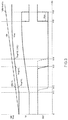
- FIG. 3 is a diagram illustrating input/output characteristics of the second comparison example
- FIG. 4 is a diagram of a voltage monitoring apparatus according to a first embodiment
- FIG. 5 is a diagram illustrating input/output characteristics according to the first embodiment
- FIG. 6 is a diagram of a voltage monitoring apparatus according to a second embodiment
- FIG. 7 is a diagram of a voltage monitoring apparatus according to a third embodiment.
- FIG. 8 is a diagram of an example of a delay operation.
- FIG. 1 shows a diagram of a first comparison example of a voltage monitoring apparatus.
- a voltage monitoring apparatus 1 is a semiconductor integrated circuit apparatus (a so-called reset IC), which monitors whether an input voltage VIN (e.g., a maximum value of 7 V) is currently rising and outputs a reset signal RST, and includes a reference voltage generating portion 10 , a divided voltage generating portion 20 and an input voltage monitoring portion 30 .
- VIN e.g., a maximum value of 7 V
- the voltage monitoring apparatus 1 further includes external terminals T 1 to T 3 as mechanisms for establishing electrical connection to the outside of the apparatus.
- the external terminal T 1 is a power terminal receiving the input voltage VIN.
- the external terminal T 2 is an output terminal for outputting the reset signal RST, and is connected to an application terminal of a boost voltage VPU through an externally installed resistor RL.
- the external terminal T 3 is a ground terminal connected to a ground terminal.
- the voltage monitoring apparatus 1 may further include constituting components or external terminals other than those described above. Further, in the voltage monitoring apparatus 1 , various parasitic devices (e.g., parasitic diodes) are attached to the components: however, to keep the drawings simple, these parasitic devices are omitted from the drawings.
- various parasitic devices e.g., parasitic diodes
- the reference voltage generating portion 10 is connected between the external terminal T 1 and the external terminal T 3 , and generates a predetermined reference voltage Vref according to the input voltage VIN. Furthermore, a band-gap power supply having a small power supply dependency or a low temperature dependency is preferably used for the reference voltage generating portion 10 .
- a resistance ladder four resistors 21 to 24 are depicted as an example in this drawing
- the divided voltage Vx is led out from a connecting node between the resistors 22 and 23 ; however, the lead-out point of the divided voltage Vx may be any as desired. Moreover, the respective resistance values of the resistors 21 to 24 may be slightly adjusted by trimming. As such, more ideally, the divided voltage generating portion 20 has a function of being capable of adjusting the voltage divider ratio ⁇ of the divided voltage Vx as desired.
- the input voltage monitoring portion 30 is a circuit block that receives the power supply of the input voltage VIN from the external voltage T 1 to operate accordingly, and includes a comparator 31 (equivalent to a first comparator) and NMOSFETs 32 and 33 .
- the comparator 31 compares the reference voltage Vref inputted to the non-inverting input terminal (+) with the divided voltage Vx inputted to the inverting input terminal ( ⁇ ) to generate a comparison signal S 1 . Furthermore, an upper-side power terminal of the comparator 31 is connected to an application terminal (i.e., the external terminal T 1 ) of the input voltage VIN, and a lower-side power terminal of the comparator 31 is connected to an application terminal (i.e., the external terminal T 3 ) of a ground voltage GND.
- the NMOSFET 32 is an output transistor that is turned on/off according to the comparison signal S 1 , and forms an open-drain output stage for outputting the reset signal RST. To describe the connection relationship, the drain of the NMOSFET 32 is connected to the external terminal T 2 , the source of the NMOSFET 32 is connected to the external terminal T 3 , and the gate of the NMOSFET 32 is connected to the application terminal of the comparison signal S 1 .
- the NMOSFET 32 is turned on if the comparison signal S 1 is at a high level ( ⁇ VIN), and so the reset signal RST becomes low level ( ⁇ GND). On the other hand, the NMOSFET 32 is turned off if the comparison signal S 1 is at a low level ( ⁇ GND), and so the reset signal RST becomes high level ( ⁇ VPU).
- the NMOSFET 33 is a hysteresis providing transistor that is turned on/off according to the comparison signal S 1 .
- the drain of the NMOSFET 33 is connected to a connecting node between the resistors 23 and 24
- the source of the NMOSFET 33 is connected to the external terminal T 3
- the gate of the NMOSFET 33 is connected to the application terminal of the comparison signal S 1 .
- the comparison signal S 1 is at a high level ( ⁇ VIN)
- the NMOSFET 33 is turned on and two terminals of the resistor 24 are short circuit, and so the voltage divider ratio ⁇ of the divided voltage Vx is decreased.
- the comparison signal S 1 is at a low level ( ⁇ GND)
- the NMOSFET 33 is turned off and two terminals of the resistor 24 are open circuit, and so the voltage divider ratio ⁇ of the divided voltage Vx is increased.
- a predetermined hysteresis voltage Vhys is provided between a reset release voltage (equivalent to the reset signal RST rising from a low level to the upper-side threshold voltage at a high level) and a reset detection voltage (equivalent to the reset signal RST lowering from a high level to the lower-side threshold voltage at a low level) of the input voltage VIN.
- the voltage monitoring apparatus 1 in the first comparison example monitors a low voltage tolerant device having a low input voltage VIN (e.g., with a maximum of 7 V).
- VIN a low voltage tolerant device having a low input voltage VIN
- the reference voltage generating portion 10 and the input voltage monitoring portion 30 include a low voltage tolerant device (e.g., a 7-V tolerant device)
- the input voltage VIN may be directly inputted as the respective power voltages.
- the voltage monitoring apparatus 1 in the first comparison example is capable of reliably lowering the reset signal RST in advance to a low level.
- FIG. 2 shows a diagram of a second comparison example of a voltage monitoring apparatus.
- the voltage monitoring apparatus 1 in the second comparison example is theoretically a high voltage tolerant device that is able to receive an input of the input voltage VIN (e.g., a maximum of 60 V) higher than that of the first comparison example ( FIG. 1 ), and further includes an inner voltage generating portion 40 .
- the inner voltage generating portion 40 is a linear regulator, such as LDO (low drop-out) regulator that lowers the input voltage VIN to generate an inner voltage Vreg (e.g., 5 V), and includes an NMOSFET 41 and a gate controller 42 .
- LDO low drop-out
- the drain of the NMOSFET 41 is connected to the external terminal T 1 (i.e., the input terminal of the input voltage VIN), the source of the NMOSFET 41 serves as an output terminal of the inner voltage Vreg and is connected to the reference voltage generating portion 10 and the input voltage monitoring portion 30 (particularly the upper-side power terminal of the comparator 31 ), and the gate of the NMOSFET 41 is connected to the gate controller 42 .
- the gate controller 42 receives a power supply of the input voltage VIN from the external terminal T 1 to operate, and performs gate controls of the NMOSFET 41 so as to coincide the inner voltage Vreg with an expected target value. More specifically, if the inner voltage Vreg is lower than the target value, the gate voltage of the NMOSFET 41 is increased and the on resistance value of the NMOSFET 41 is reduced, such that the inner voltage Vreg rises. Conversely, if the inner voltage Vreg is higher than the target value, the gate voltage of the NMOSFET 41 is reduced and the on resistance value of the NMOSFET 41 is increased, such that the inner voltage Vreg drops.
- the reference voltage generating portion 10 and the input voltage monitoring portion 30 receive, instead of the direct input of the input voltage VIN as the respective power voltages, the input of the even lower inner voltage Vreg as the respective power voltages to operate.
- the reference voltage generating portion 10 and the input voltage monitoring portion 30 may include low voltage tolerant devices (e.g., 5-V tolerant devices).
- FIG. 3 shows a diagram illustrating input/output characteristics of the second comparison example.
- the input voltage VIN dashed line
- the inner voltage Vreg solid line
- the comparison signal S 1 and the reset signal RST are depicted.
- the horizontal axis of this diagram represents the input voltage VIN (herein, 0 ⁇ V11 ⁇ V12 ⁇ V13 ⁇ V14 ⁇ V15 ⁇ V16).
- the input voltage VIN has reached the minimum operating voltage VL of the reference voltage generating portion 10 and the input voltage monitoring portion 30 .
- the reset signal RST may be lowered to a low level (referring to the dotted line of RST) at that time point.
- the voltage monitoring apparatus 1 in the second comparison example is able to lower the reset signal RST to a low level (referring to the solid line of RST) only at that time point.
- the NMOSFET 32 be able to withstand a high voltage (e.g., 60-V tolerant).
- the turn-on threshold voltage Vth of the NMOSFET 32 rises, in a way that the minimum operating voltage VL of the input voltage monitoring portion 30 is increased (VL ⁇ VL′).
- the input voltage VIN required for the inner voltage Vreg reaching the minimum operating voltage VL′ of the input voltage monitoring portion 30 further increases.
- the inner voltage Vreg has reached the minimum operating voltage VL′ of the input voltage monitoring portion 30 . That is, by designing the NMOSFET 32 to have a high voltage tolerance, the minimum operating voltage of the voltage monitoring apparatus 1 further rises from the voltage value V13 to the voltage value V14 (referring to the long dashed line of RST).
- the comparison signal S 1 lowers from a high level ( ⁇ Vreg) to a low level ( ⁇ GND).
- the reset signal RST rises from a low level ( ⁇ GND) to a high level ( ⁇ VPU).
- the voltage values V15 and V16 are respectively equivalent to the reset detection voltage and the reset release voltage of the input voltage VIN, with a hysteresis voltage Vhys being provided between the two.
- FIG. 4 shows a diagram of a voltage monitoring apparatus according to a first embodiment of the present invention.
- the voltage monitoring apparatus 1 of the first embodiment is based on the second comparison example ( FIG. 2 ) in the description above, and further includes a switch portion 50 and a switch driving portion 60 .
- These circuit components 51 to 53 are formed by high voltage tolerant devices (e.g., 60-V tolerant) capable of withstanding the application of the input voltage VIN.
- the drain of the NMOSFET 52 is connected to the gate of the PMOSFET 51 , the source of the NMOSFET 52 is connected to a ground terminal (equivalent to the external terminal T 3 ), and the gate of the NMOSFET 52 is connected to an output terminal (equivalent to an output terminal of a comparison signal S 2 below) of the switch driving portion 60 .
- the NMOSFET 52 is turned on if the comparison signal S 2 is at a high level ( ⁇ Vreg or VIN), and is turned off if the comparison signal S 2 is at a low level ( ⁇ GND).
- a first terminal of the current source 53 is connected to the input terminal of the input voltage VIN, and a second terminal of the current source 53 is connected to the gate of the PMOSFET 51 . Furthermore, the current source 53 may also be replaced by a load such as a resistor.
- the NMOSFET 52 and the current source 53 function as an inverter below, that is, inverting the logic level of the comparison signal S 2 to generate and output an inverted comparison signal S 2 B to the gate of the PMOSFET 51 .
- the inverted comparison signal S 2 B becomes low level ( ⁇ GND); conversely, if the comparison signal S 2 is at a low level ( ⁇ GND), the inverted comparison signal S 2 B becomes high level ( ⁇ VIN).
- the inverted comparison signal S 2 B is at a low level ( ⁇ GND)
- the PMOSFET 51 is turned on, and Vreg is equal to VIN.
- the inverted comparison signal S 2 B is at a high level ( ⁇ VIN)
- the PMOSFET 51 is turned off, and Vreg is not equal to VIN.
- the switch driving portion 60 is a circuit block that turns on the switch portion 50 if the input voltage VIN is lower than a threshold voltage, and turns off the switch portion 50 if the input voltage VIN is higher than the threshold voltage, and includes a comparator 61 (equivalent to a second comparator).
- the comparator 61 compares the reference voltage Vref inputted to the non-inverting input terminal (+) thereof with a divided voltage Vy(>Vx) inputted to the inverting input terminal ( ⁇ ) thereof to generate a comparison signal S 2 . Furthermore, similar to the divided voltage Vx, the divided voltage Vy is generated by the divided voltage generating portion 20 .
- the divided voltage Vx is led out from a connecting node between the resistors 22 and 23
- the divided voltage Vy is led out from a connecting node between the resistors 21 and 22 ; however, the lead-out points of the divided voltages Vx and Vy may be any as desired.
- the respective resistance values of the resistors 21 to 24 may be slightly adjusted by trimming.
- the divided voltage generating portion 20 has a function of being capable of adjusting the respective voltage divider ratios ⁇ and ⁇ of the divided voltages Vx and Vy as desired.
- an upper-side power terminal of the comparator 61 is connected to the output terminal of the inner voltage generating portion 40 , and a lower-side power terminal of the comparator 61 is connected to an application terminal (equivalent to the external terminal T 3 ) of the ground voltage GND.
- the comparison signal S 2 becomes high level ( ⁇ Vreg or VIN) if Vy ⁇ Vref (and hence VIN ⁇ Vref/ ⁇ ), and becomes low level ( ⁇ GND) if Vy>Vref (and hence VIN>Vref/ ⁇ ).
- the comparator 61 may include a low voltage tolerant device (e.g., a 5-V tolerant device).
- the voltage monitoring apparatus 1 of this embodiment is capable of lowering the minimum operating voltage by the switch portion 50 and the switch driving portion 60 introduced, wherein the minimum operating voltage is for reliably lowering the reset signal RST in advance to a low level. Details of such characteristic above are given with the accompanying drawings below.
- FIG. 5 shows a diagram illustrating input/output characteristics of the first embodiment.
- the input voltage VIN dashed line
- the inner voltage Vreg solid line
- the comparison signal S 1 the comparison signal S 2
- the inverted comparison signal S 2 B and the reset signal RST are depicted.
- behaviors of the second comparison example FIG. 3
- the horizontal axis of this drawing represents the input voltage VIN (herein, 0 ⁇ V21 ⁇ V22 ⁇ V23 ⁇ V24 ⁇ V25 ⁇ V26).
- a target value e.g. 5 V.
- the comparison signal S 2 is at a high level, the inverted comparison signal S 2 B becomes low level, the switch portion 50 is turned on, and Vreg becomes equal to VIN.
- the respective high levels ( ⁇ VIN) of the comparison signals S 1 and S 2 also gradually rise.
- the input voltage VIN has reached the minimum operating voltage VL of the reference voltage generating portion 10 and the input voltage monitoring portion 30 .
- the switch portion 50 is turned on, and Vreg is equal to VIN.
- the input voltage VIN is inputted as the respective power voltages of the reference voltage generating portion 10 and the input voltage monitoring portion 30 , and the reset signal RST may be lowered to a low level (referring to the solid line of RST) at that time point.
- the switch portion 50 is not turned on, and the inner voltage Vreg lower than the input voltage VIN is inputted as the respective power voltages of the reference voltage generating portion 10 and the input voltage monitoring portion 30 .
- the switch portion 50 may be conducted to eliminate the difference between the input voltage VIN and the inner voltage Vreg, such that the minimum operating voltage of the voltage monitoring apparatus 1 may be lowered from the voltage value V23 to the voltage value V22.
- Vreg is not equal to VIN.
- the inner voltage Vreg is inputted to the reference voltage generating portion 10 , the input voltage monitoring portion 30 and the switch driving portion 60 as the respective power voltages thereof. For example, a high level of the comparison signal S 1 switches from the input voltage VIN to the inner voltage Vreg.
- the comparison signal S 1 lowers from a high level ( ⁇ Vreg) to a low level ( ⁇ GND).
- the reset signal RST rises from a low level ( ⁇ GND) to a high level ( ⁇ VPU).
- the voltage values V25 and V26 are respectively equivalent to the reset detection voltage and the reset release voltages of the input voltage VIN, with a hysteresis voltage Vhys provided between the two.
- the normal operation of the voltage monitoring apparatus 1 is not different from that of the second comparison example ( FIG. 3 ) in the description above.
- the switch driving portion 60 turns on the switch portion 50 if the input voltage VIN is lower than the shield release voltage ( ⁇ Vref/r), and on the other hand, turns off the switch portion 50 if the input voltage VIN is higher than the shield release voltage. That is, in a low-input region (VIN ⁇ Vref/ ⁇ ), the difference between the input voltage VIN and the inner voltage Vreg may be eliminated.
- the concern of damage of the gate-source withstand voltage of the PMOSFET 51 during a turned-on period (S 2 B ⁇ GND) of the switch portion 50 may be eliminated.
- the gate-source withstand voltage (e.g., 7-V tolerant) of the PMOSFET 51 is not as high as the drain-source withstand voltage (e.g., 60-V tolerant), and hence such setting is extremely critical.
- the gate-source voltage of the PMOSFET 51 becomes zero. Thus, even if the input voltage VIN rises, damage of gate-source withstand voltage of the PMOSFET 51 is not incurred.
- FIG. 6 shows a diagram of a voltage monitoring apparatus according to a second embodiment.
- the divided voltage generating portion 20 is configured as below, that is, including n resistors 21 ( 1 ) to 21 ( n ) as the resistor 21 described above, and a voltage selecting portion 25 selecting one of divided voltages Vy( 1 ) to Vy(n) led out from connecting nodes between these resistors as the divided voltage Vy described above.
- the voltage selecting portion 25 dynamically performs voltage selection according to a control signal inputted from the outside of the voltage monitoring apparatus 1 , or a control signal read from a memory (not shown) of the voltage monitoring apparatus 1 .
- a voltage selection state of the voltage selecting portion 25 may also be fixedly configured by trimming in a manufacturing phase of the voltage monitoring apparatus 1 .
- the voltage divider ratio ⁇ of the divided voltage Vy may be easily adjusted as desired. For example, when the withstand voltage of the NMOSFET 32 is changed, only the voltage divider ratio ⁇ (hence the shield release voltage Vref/ ⁇ ) of the divided voltage Vy needs to be correspondingly and appropriately adjusted.
- a mechanism for adjusting the voltage divider ratio ⁇ is given as an example.
- the same configuration may also be adopted with respect to a mechanism for adjusting the voltage divider ratio ⁇ .
- FIG. 7 shows a diagram of a voltage monitoring apparatus according to a third embodiment.
- the input voltage monitoring portion 30 further includes a delay portion 34 between the output terminal of the comparator 31 and the gate of the NMOSFET 32 .
- the delay portion 34 is a circuit block which provides the comparison signal S 1 with a delay to generate a delayed comparison signal S 1 D and outputs the delayed comparison signal S 1 D to the gate of the NMOSFET 32 , and may be implemented by a RC (resistance-capacitance) time-constant circuit or a fixed current circuit.
- RC resistance-capacitance
- FIG. 8 shows a diagram of an example of a delay operation of the delay portion 34 . In an order from top to bottom, the comparison signal S 1 and the delayed comparison signal S 1 D are depicted.
- the pulse edge timing (hence the pulse edge timing of the reset signal RST) of the delayed comparison signal S 1 D may be adjusted as desired.
- the invention disclosed by the present disclosure may be applied to a voltage monitoring apparatus (e.g., a reset IC applied to vehicles) in need of monitoring a high input voltage.
- a voltage monitoring apparatus e.g., a reset IC applied to vehicles
Landscapes
- Physics & Mathematics (AREA)
- General Physics & Mathematics (AREA)
- Engineering & Computer Science (AREA)
- Power Engineering (AREA)
- Theoretical Computer Science (AREA)
- Nonlinear Science (AREA)
- General Engineering & Computer Science (AREA)
- Measurement Of Current Or Voltage (AREA)
- Electronic Switches (AREA)
- Logic Circuits (AREA)
- Semiconductor Integrated Circuits (AREA)
Abstract
Description
- [Patent document 1] Japan Patent Publication No. 2018-117235
Claims (12)
Applications Claiming Priority (3)
| Application Number | Priority Date | Filing Date | Title |
|---|---|---|---|
| JP2019075666 | 2019-04-11 | ||
| JPJP2019-075666 | 2019-04-11 | ||
| JP2019075666A JP7327980B2 (en) | 2019-04-11 | 2019-04-11 | voltage monitor |
Publications (2)
| Publication Number | Publication Date |
|---|---|
| US20200326359A1 US20200326359A1 (en) | 2020-10-15 |
| US11079416B2 true US11079416B2 (en) | 2021-08-03 |
Family
ID=72747670
Family Applications (1)
| Application Number | Title | Priority Date | Filing Date |
|---|---|---|---|
| US16/844,381 Active US11079416B2 (en) | 2019-04-11 | 2020-04-09 | Voltage monitoring apparatus |
Country Status (3)
| Country | Link |
|---|---|
| US (1) | US11079416B2 (en) |
| JP (1) | JP7327980B2 (en) |
| CN (1) | CN111813211B (en) |
Families Citing this family (3)
| Publication number | Priority date | Publication date | Assignee | Title |
|---|---|---|---|---|
| JP2021018217A (en) * | 2019-07-24 | 2021-02-15 | ローム株式会社 | Voltage monitoring circuit |
| KR102602246B1 (en) * | 2020-09-01 | 2023-11-13 | 삼성에스디아이 주식회사 | Comparator circuit and switch control device including the same |
| TWI883510B (en) * | 2023-08-16 | 2025-05-11 | 立積電子股份有限公司 | Protection circuit and protection method |
Citations (1)
| Publication number | Priority date | Publication date | Assignee | Title |
|---|---|---|---|---|
| JP2018117235A (en) | 2017-01-18 | 2018-07-26 | 株式会社ミツトヨ | Power-on reset circuit |
Family Cites Families (7)
| Publication number | Priority date | Publication date | Assignee | Title |
|---|---|---|---|---|
| JPH07122992B2 (en) * | 1990-02-08 | 1995-12-25 | 株式会社東芝 | Semiconductor integrated circuit |
| JP3881337B2 (en) | 2003-12-26 | 2007-02-14 | ローム株式会社 | Signal output circuit and power supply voltage monitoring apparatus having the same |
| JP4522738B2 (en) | 2004-03-31 | 2010-08-11 | 京セラ株式会社 | Power-on reset device and electronic device |
| JP4233552B2 (en) | 2005-08-30 | 2009-03-04 | 富士通株式会社 | Reset device |
| JP5063939B2 (en) | 2006-06-20 | 2012-10-31 | オンセミコンダクター・トレーディング・リミテッド | Microcomputer |
| JP5163211B2 (en) | 2008-03-24 | 2013-03-13 | ミツミ電機株式会社 | Semiconductor integrated circuit for reset circuit and power supply control |
| JP6072585B2 (en) * | 2013-03-28 | 2017-02-01 | ローム株式会社 | Semiconductor device |
-
2019
- 2019-04-11 JP JP2019075666A patent/JP7327980B2/en active Active
-
2020
- 2020-04-09 US US16/844,381 patent/US11079416B2/en active Active
- 2020-04-10 CN CN202010280548.1A patent/CN111813211B/en active Active
Patent Citations (1)
| Publication number | Priority date | Publication date | Assignee | Title |
|---|---|---|---|---|
| JP2018117235A (en) | 2017-01-18 | 2018-07-26 | 株式会社ミツトヨ | Power-on reset circuit |
Also Published As
| Publication number | Publication date |
|---|---|
| JP2020174293A (en) | 2020-10-22 |
| JP7327980B2 (en) | 2023-08-16 |
| CN111813211A (en) | 2020-10-23 |
| CN111813211B (en) | 2024-05-28 |
| US20200326359A1 (en) | 2020-10-15 |
Similar Documents
| Publication | Publication Date | Title |
|---|---|---|
| US8754628B2 (en) | Voltage regulator for high speed switching of voltages | |
| US9293990B2 (en) | Switching regulator and electronic apparatus | |
| US10534390B2 (en) | Series regulator including parallel transistors | |
| US11079416B2 (en) | Voltage monitoring apparatus | |
| CN110531143B (en) | Voltage detector | |
| US20140167714A1 (en) | Soft-start circuits and power suppliers using the same | |
| US8766679B1 (en) | Power on reset (POR) circuit | |
| US11114880B2 (en) | Current regulating circuit and power supply management circuit including the same | |
| US9917573B2 (en) | Voltage detection circuit | |
| US10886838B2 (en) | Semiconductor integrated circuit for discharging and power supply system | |
| US8310287B2 (en) | Reset circuit and control apparatus including the reset circuit | |
| US20100195358A1 (en) | Voltage regulator and ac-dc converter | |
| US11105830B2 (en) | Voltage detector | |
| US10498215B1 (en) | Voltage regulator with flexible output voltage | |
| US20160187900A1 (en) | Voltage regulator circuit and method for limiting inrush current | |
| US7196502B2 (en) | Switching regulator having soft start circuit | |
| JP6543133B2 (en) | POWER SUPPLY DEVICE AND ITS CONTROL METHOD | |
| US9727075B2 (en) | Power-supply voltage sensing circuit | |
| US10644694B2 (en) | Power-on reset circuit with hysteresis | |
| US20160026200A1 (en) | Power supply circuit | |
| US11994892B2 (en) | Shunt regulator | |
| US12230956B2 (en) | Current limiting circuits | |
| JP4594064B2 (en) | Surge current suppression circuit and DC power supply device | |
| TWI581548B (en) | Auto-adjustment current limiting circuit of a non-isolation switching power circuit | |
| JP2025110693A (en) | Power supply circuit and drive circuit |
Legal Events
| Date | Code | Title | Description |
|---|---|---|---|
| FEPP | Fee payment procedure |
Free format text: ENTITY STATUS SET TO UNDISCOUNTED (ORIGINAL EVENT CODE: BIG.); ENTITY STATUS OF PATENT OWNER: LARGE ENTITY |
|
| AS | Assignment |
Owner name: ROHM CO., LTD., JAPAN Free format text: ASSIGNMENT OF ASSIGNORS INTEREST;ASSIGNOR:TERASAKI, FUMIHIKO;REEL/FRAME:052476/0514 Effective date: 20200310 |
|
| STPP | Information on status: patent application and granting procedure in general |
Free format text: DOCKETED NEW CASE - READY FOR EXAMINATION |
|
| STPP | Information on status: patent application and granting procedure in general |
Free format text: NOTICE OF ALLOWANCE MAILED -- APPLICATION RECEIVED IN OFFICE OF PUBLICATIONS |
|
| STPP | Information on status: patent application and granting procedure in general |
Free format text: PUBLICATIONS -- ISSUE FEE PAYMENT RECEIVED |
|
| STPP | Information on status: patent application and granting procedure in general |
Free format text: PUBLICATIONS -- ISSUE FEE PAYMENT VERIFIED |
|
| STCF | Information on status: patent grant |
Free format text: PATENTED CASE |
|
| MAFP | Maintenance fee payment |
Free format text: PAYMENT OF MAINTENANCE FEE, 4TH YEAR, LARGE ENTITY (ORIGINAL EVENT CODE: M1551); ENTITY STATUS OF PATENT OWNER: LARGE ENTITY Year of fee payment: 4 |