US11076083B2 - Multi-color flash with image post-processing - Google Patents
Multi-color flash with image post-processing Download PDFInfo
- Publication number
- US11076083B2 US11076083B2 US16/704,864 US201916704864A US11076083B2 US 11076083 B2 US11076083 B2 US 11076083B2 US 201916704864 A US201916704864 A US 201916704864A US 11076083 B2 US11076083 B2 US 11076083B2
- Authority
- US
- United States
- Prior art keywords
- image
- color point
- scene
- color
- light sources
- Prior art date
- Legal status (The legal status is an assumption and is not a legal conclusion. Google has not performed a legal analysis and makes no representation as to the accuracy of the status listed.)
- Active
Links
Images


Classifications
-
- H04N5/232—
-
- G—PHYSICS
- G03—PHOTOGRAPHY; CINEMATOGRAPHY; ANALOGOUS TECHNIQUES USING WAVES OTHER THAN OPTICAL WAVES; ELECTROGRAPHY; HOLOGRAPHY
- G03B—APPARATUS OR ARRANGEMENTS FOR TAKING PHOTOGRAPHS OR FOR PROJECTING OR VIEWING THEM; APPARATUS OR ARRANGEMENTS EMPLOYING ANALOGOUS TECHNIQUES USING WAVES OTHER THAN OPTICAL WAVES; ACCESSORIES THEREFOR
- G03B15/00—Special procedures for taking photographs; Apparatus therefor
- G03B15/02—Illuminating scene
- G03B15/03—Combinations of cameras with lighting apparatus; Flash units
- G03B15/05—Combinations of cameras with electronic flash apparatus; Electronic flash units
-
- G—PHYSICS
- G03—PHOTOGRAPHY; CINEMATOGRAPHY; ANALOGOUS TECHNIQUES USING WAVES OTHER THAN OPTICAL WAVES; ELECTROGRAPHY; HOLOGRAPHY
- G03B—APPARATUS OR ARRANGEMENTS FOR TAKING PHOTOGRAPHS OR FOR PROJECTING OR VIEWING THEM; APPARATUS OR ARRANGEMENTS EMPLOYING ANALOGOUS TECHNIQUES USING WAVES OTHER THAN OPTICAL WAVES; ACCESSORIES THEREFOR
- G03B33/00—Colour photography, other than mere exposure or projection of a colour film
- G03B33/02—Colour photography, other than mere exposure or projection of a colour film by two-colour separation records, e.g. red-aspect and white complete records; using Land effect
-
- G06T5/001—
-
- G—PHYSICS
- G06—COMPUTING OR CALCULATING; COUNTING
- G06T—IMAGE DATA PROCESSING OR GENERATION, IN GENERAL
- G06T5/00—Image enhancement or restoration
- G06T5/50—Image enhancement or restoration using two or more images, e.g. averaging or subtraction
-
- G—PHYSICS
- G06—COMPUTING OR CALCULATING; COUNTING
- G06T—IMAGE DATA PROCESSING OR GENERATION, IN GENERAL
- G06T5/00—Image enhancement or restoration
- G06T5/90—Dynamic range modification of images or parts thereof
- G06T5/92—Dynamic range modification of images or parts thereof based on global image properties
-
- H—ELECTRICITY
- H04—ELECTRIC COMMUNICATION TECHNIQUE
- H04N—PICTORIAL COMMUNICATION, e.g. TELEVISION
- H04N23/00—Cameras or camera modules comprising electronic image sensors; Control thereof
- H04N23/56—Cameras or camera modules comprising electronic image sensors; Control thereof provided with illuminating means
-
- H—ELECTRICITY
- H04—ELECTRIC COMMUNICATION TECHNIQUE
- H04N—PICTORIAL COMMUNICATION, e.g. TELEVISION
- H04N23/00—Cameras or camera modules comprising electronic image sensors; Control thereof
- H04N23/60—Control of cameras or camera modules
-
- H—ELECTRICITY
- H04—ELECTRIC COMMUNICATION TECHNIQUE
- H04N—PICTORIAL COMMUNICATION, e.g. TELEVISION
- H04N23/00—Cameras or camera modules comprising electronic image sensors; Control thereof
- H04N23/70—Circuitry for compensating brightness variation in the scene
- H04N23/74—Circuitry for compensating brightness variation in the scene by influencing the scene brightness using illuminating means
-
- H—ELECTRICITY
- H04—ELECTRIC COMMUNICATION TECHNIQUE
- H04N—PICTORIAL COMMUNICATION, e.g. TELEVISION
- H04N23/00—Cameras or camera modules comprising electronic image sensors; Control thereof
- H04N23/70—Circuitry for compensating brightness variation in the scene
- H04N23/743—Bracketing, i.e. taking a series of images with varying exposure conditions
-
- H—ELECTRICITY
- H04—ELECTRIC COMMUNICATION TECHNIQUE
- H04N—PICTORIAL COMMUNICATION, e.g. TELEVISION
- H04N23/00—Cameras or camera modules comprising electronic image sensors; Control thereof
- H04N23/80—Camera processing pipelines; Components thereof
- H04N23/84—Camera processing pipelines; Components thereof for processing colour signals
- H04N23/88—Camera processing pipelines; Components thereof for processing colour signals for colour balance, e.g. white-balance circuits or colour temperature control
-
- H04N5/2256—
-
- G—PHYSICS
- G03—PHOTOGRAPHY; CINEMATOGRAPHY; ANALOGOUS TECHNIQUES USING WAVES OTHER THAN OPTICAL WAVES; ELECTROGRAPHY; HOLOGRAPHY
- G03B—APPARATUS OR ARRANGEMENTS FOR TAKING PHOTOGRAPHS OR FOR PROJECTING OR VIEWING THEM; APPARATUS OR ARRANGEMENTS EMPLOYING ANALOGOUS TECHNIQUES USING WAVES OTHER THAN OPTICAL WAVES; ACCESSORIES THEREFOR
- G03B2215/00—Special procedures for taking photographs; Apparatus therefor
- G03B2215/05—Combinations of cameras with electronic flash units
- G03B2215/0564—Combinations of cameras with electronic flash units characterised by the type of light source
- G03B2215/0571—With second light source
-
- G—PHYSICS
- G06—COMPUTING OR CALCULATING; COUNTING
- G06T—IMAGE DATA PROCESSING OR GENERATION, IN GENERAL
- G06T2207/00—Indexing scheme for image analysis or image enhancement
- G06T2207/10—Image acquisition modality
- G06T2207/10024—Color image
-
- G—PHYSICS
- G06—COMPUTING OR CALCULATING; COUNTING
- G06T—IMAGE DATA PROCESSING OR GENERATION, IN GENERAL
- G06T2207/00—Indexing scheme for image analysis or image enhancement
- G06T2207/10—Image acquisition modality
- G06T2207/10141—Special mode during image acquisition
- G06T2207/10152—Varying illumination
-
- G—PHYSICS
- G06—COMPUTING OR CALCULATING; COUNTING
- G06T—IMAGE DATA PROCESSING OR GENERATION, IN GENERAL
- G06T2207/00—Indexing scheme for image analysis or image enhancement
- G06T2207/20—Special algorithmic details
- G06T2207/20212—Image combination
-
- G—PHYSICS
- G06—COMPUTING OR CALCULATING; COUNTING
- G06T—IMAGE DATA PROCESSING OR GENERATION, IN GENERAL
- G06T2207/00—Indexing scheme for image analysis or image enhancement
- G06T2207/20—Special algorithmic details
- G06T2207/20212—Image combination
- G06T2207/20216—Image averaging
-
- G—PHYSICS
- G06—COMPUTING OR CALCULATING; COUNTING
- G06T—IMAGE DATA PROCESSING OR GENERATION, IN GENERAL
- G06T2207/00—Indexing scheme for image analysis or image enhancement
- G06T2207/20—Special algorithmic details
- G06T2207/20212—Image combination
- G06T2207/20221—Image fusion; Image merging
Definitions
- the present disclosure relates generally to cameras and, more specifically, to cameras with a multi-color flash.
- Camera flashes provide illumination in low-light conditions.
- the color of the flash should match that of the subject and/or the full image. This can be accomplished by using a collection of light sources of different colors so that the combined color point produced by the collection matches that of the subject and/or the full image. Due to their compact size and low power requirements, light-emitting diodes (LEDs) are attractive candidates for light sources used in camera flashes for hand-held, battery-powered devices, such as cameras and cell phones.
- LEDs light-emitting diodes
- FIG. 1 provides a block diagram illustrating an example camera device, according to some embodiments of the present disclosure
- FIG. 2 provides a flow chart of a method for performing multi-flash with image post-processing, according to some embodiments of the present disclosure
- FIG. 3 provides an example plot illustrating color points of flashes of two different colors and a color point of ambient lighting, according to some embodiments of the present disclosure
- FIG. 4 illustrates an example of using the plot of FIG. 3 to compute a correction factor with respect to the flash of the first color, according to some embodiments of the present disclosure
- FIG. 5 illustrates an example of using the plot of FIG. 3 to compute a correction factor with respect to the flash of the second color, according to some embodiments of the present disclosure
- FIG. 6 illustrates an example of using the plot of FIG. 3 to compute a correction factor with respect to the flashes of both colors, according to some embodiments of the present disclosure.
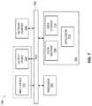
- FIG. 7 provides a block diagram illustrating an example data processing system that may be configured to implement at least portions of multi-color flash with image post-processing as described herein, according to some embodiments of the present disclosure.
- LED flash in cameras provides illumination for when images are acquired in low-light conditions.
- the color of the flash should match that of the subject and/or the full image, which can be accomplished by using a collection of light sources of different colors to set the optimal color point.
- One conventional method to set the right color point is to, first, measure the color point with a camera or other device and, next, tune the collection of LEDs to adjusting the current used to drive each of the LEDs.
- One challenge with such an approach is that the measurement and tuning should all be done in between the time when the user pushes the button to acquire an image and the time when the camera actually acquires the image.
- Embodiments of the present disclosure provide an approach that may be referred to as “multi-color flash with image post-processing” in that it uses a camera device with a multi-color flash (i.e., flashes of at least two different colors or color points) and implements post-processing (i.e., processing after the images have been acquired by a camera) to generate images.
- a camera device with a multi-color flash i.e., flashes of at least two different colors or color points
- post-processing i.e., processing after the images have been acquired by a camera
- the multi-color flash with image post-processing may be implemented by a controller configured to control a camera and flashes of at least two different colors (or associated with at least two different color points), referred to as a “first flash” and a “second flash.”
- first flash may refer to a collection of light sources, e.g., a collection of LEDs, which, when the first flash is used when an image is acquired, cause the image to be associate with a first color point.
- second flash may refer to a collection of light sources, e.g., a collection of LEDs, which, when the second flash is used when an image is acquired, cause the image to be associate with a second color point, different from the color point.
- the controller may be configured to cause the camera to acquire a first image of a scene while the scene is being illuminated with the first flash but not the second flash (which may cause the first image to be associated with a first color point), then cause the camera to acquire a second image of the scene while the scene is being illuminated with the second flash but not the first flash (which may cause the second image to be associated with a second color point, different from the first color point), and generate a final image of the scene in post-processing based on a combination of the first image and the second image.
- the final image may be generated as a weighted average, a squared weighted average, a weighted median, or any other suitable combination of the first and second images to represent the desired balance between the first and second flashes in the final image.
- selection of the optimal/desired color point for the multi-color flash may be performed in post-processing, which may alleviate some of the demands or requirements on the pre-processing steps that have to be performed, advantageously allowing to, e.g., use a less complicated processing unit, which may lead to significant cost savings.
- the post-processing of generating the final image may be performed by an application-layer processor.
- the multi-color flash is described with reference to flashes of two different colors (or color points).
- the first flash could be such that the first color point is a color point of a cold white (CW) color and the second flash could be such that the second color point is a color point of a warm white (WW) color.
- CW cold white
- WW warm white
- these descriptions can be easily extended to other embodiments where other colors of the first and second flashes may be used, and/or where flashes of more than two different colors may be used, all of which embodiments being within the scope of the present disclosure.
- LEDs any suitable light sources, not limited to the LEDs, may be used.
- each flash may be implemented as a collection of light sources, e.g., a collection of LEDs, embodiments could be envisioned where at no point of acquiring the images with different color flashes as described herein all of the LEDs are off.
- descriptions referring to acquiring a given image while a given flash is illuminating the scene and while other flashes are not illuminating the scene include any embodiments where a given set of light sources emit light, each at a certain intensity (which could be different from one light source to another), resulting in illumination of the scene associated with a certain color point, different from the color points of other one or more flashes.
- multi-color flash with image post-processing described herein refers, generally, to any embodiments where multiple sequential pictures are taken with various flash color points that are combined afterwards, where the flash color point does not necessarily need to be the same as the color point of a given light source or a given set of light sources.
- aspects of the present disclosure in particular aspects of multi-color flash with image post-processing, described herein, may be embodied in various manners—e.g. as a method, a system, a computer program product, or a computer-readable storage medium. Accordingly, aspects of the present disclosure may take the form of an entirely hardware embodiment, an entirely software embodiment (including firmware, resident software, micro-code, etc.) or an embodiment combining software and hardware aspects that may all generally be referred to herein as a “circuit,” “module” or “system.” Functions described in this disclosure may be implemented as an algorithm executed by one or more hardware processing units, e.g. one or more microprocessors, of one or more computers.
- aspects of the present disclosure may take the form of a computer program product embodied in one or more computer readable medium(s), preferably non-transitory, having computer readable program code embodied, e.g., stored, thereon.
- a computer program may, for example, be downloaded (updated) to the existing devices and systems (e.g. to the existing camera devices and/or their controllers, etc.) or be stored upon manufacturing of these devices and systems.
- circuit means one or more passive and/or active components that are arranged to cooperate with one another to provide a desired function.
- the phrase “A and/or B” means (A), (B), or (A and B).
- the phrase “A, B, and/or C” means (A), (B), (C), (A and B), (A and C), (B and C), or (A, B, and C).
- the term “between,” when used with reference to measurement ranges, is inclusive of the ends of the measurement ranges.
- the notation “A/B/C” means (A), (B), and/or (C).
- interaction may be described in terms of two, three, four, or more electrical components. However, this has been done for purposes of clarity and example only. It should be appreciated that the devices and systems described herein can be consolidated in any suitable manner. Along similar design alternatives, any of the illustrated components, modules, and elements of the accompanying drawings may be combined in various possible configurations, all of which are clearly within the broad scope of the present disclosure. In certain cases, it may be easier to describe one or more of the functionalities of a given set of flows by only referencing a limited number of electrical elements.
- FIG. 1 provides a block diagram illustrating an example camera device 100 in which multi-color flash with image post-processing may be implemented, according to some embodiments of the present disclosure.
- the camera device 100 may include a first flash 102 (i.e., a flash associated with a first color point), a second flash 104 (i.e., a flash associated with a second color point), a camera 106 , a controller 108 , and, optionally, a measuring unit 110 .
- Each of the first flash 102 and the second flash 104 may include a collection of light sources, e.g., a collection of LEDs, which, when the camera 106 acquires an image with one of these flashes illuminating the scene, causes the acquired image to be associate with a different color point.
- the first flash 102 could be a CW color flash and the second flash 104 could be a WW color flash.
- a scene being illuminated with the first flash 102 may include the scene being illuminated by a first plurality of light sources of one or more of a plurality of colors
- a scene being illuminated with the second flash 104 may include the scene being illuminated by a second plurality of light sources of one or more of the plurality of colors, illumination provided by the second plurality of light sources having a different color than illumination provided by the first plurality of light sources.
- the color of a given flash (or a given light source or a collection of light sources) may originate from different emission spectra of the light source and is characterized by different location (color point) in the RGB color space of the camera 106 .
- the camera 106 may include any suitable imaging device configured to acquire images of a scene.
- the camera 106 may be communicatively coupled to the each of the first flash 102 and the second flash 104 so that these flashes may be synchronized to provide illumination of the scene when the camera 106 is acquiring images.
- the timing of acquiring images by the camera 106 and the selective engagement of the flashes 102 and 104 in providing illumination when the images are acquired may be controlled by the controller 108 , e.g., as described below.
- the controller 108 may also be configured to generate the final image of a scene based on the images acquired by the camera 106 .
- the controller 106 may be implemented as, or include at least portions of, a data processing system 700 shown in FIG. 7 .
- the measuring unit 110 may be configured to perform additional measurements that may be used by the controller 108 in generating the final images.
- the measuring unit 110 may be configured to measure one or more of ambient (white) color point, spectrum, ambient (white) RGB response, of ambient correlated color temperature (CCT), and other parameters related to acquired images, such as auto focus, auto exposure, etc.
- the measuring unit 110 may also be configured to perform measurements of, or measurements that enable calculation of, the values of Ra, Ba, Ga, described below, e.g., the values used in equations (1)-(3) provided below.
- the camera device 100 illustrates only two flashes of different colors, namely, the flashes 102 and 104 , in other embodiments, additional flashes of different colors may be included in the camera device 100 .
- the camera device 100 may include other components.
- the camera device 100 may further include an output device, configured to display, e.g., one or more of the first image, the second image, and the final image as described herein.
- the camera device 100 may further include an input device, configured to receive user input to be used by the camera device to perform one of more of 106 cause the camera to acquire the first image, cause the camera 106 to acquire the second image, and the controller 108 generate the final image.
- the camera device 100 may further include one or more communication chips and an antenna, configured to wirelessly transmit one or more of the first image, the second image, and the final image, and/or wirelessly receive input to be used by the camera device 100 to perform one of more of cause the camera to acquire the first image, cause the camera to acquire the second image, and generate the final image.
- the camera device 100 may refer to a device that includes to any combination of one or more of these components, in which case the other components shown in FIG. 1 may be implemented externally (i.e., in a separate device) and may be communicatively coupled to components of the camera device 100 as needed, via any appropriate communication channel, to implement the multi-flash with image post-processing as described herein.
- the camera device 100 may be, e.g., a wearable camera device (e.g., a smart watch), a hand-held camera device (e.g., a mobile phone), or a stationary camera (e.g., a security/surveillance camera).
- a wearable camera device e.g., a smart watch
- a hand-held camera device e.g., a mobile phone
- a stationary camera e.g., a security/surveillance camera
- FIG. 2 illustrates a flow chart of a method 200 for performing multi-flash with image post-processing, according to some embodiments of the present disclosure.
- method 200 is now described with reference to elements illustrated in FIG. 1 , any system or apparatus configured to perform various processes of this method, in any order, is within the scope of the present disclosure.
- the method 200 may begin with a process 202 which includes the controller 108 causing the camera 106 to acquire a first image of a scene while the scene is being illuminated with the first flash 102 but not with the second flash 104 .
- the controller 108 causes the camera 106 to acquire a second image of the scene while the scene is being illuminated with the second flash 102 but not with the first flash 102 .
- the processes 202 and 204 represent that the method 200 includes the camera 106 acquiring separate images with flashes of different colors, where for each of these images, one or more of the flashes are illuminating the scene during image acquisition, while one or more other flashes are off.
- the process 202 includes the controller 108 causing the camera 106 to acquire the first image while the scene is being illuminated with the first flash 102 and the ambient light
- the process 204 includes the controller 108 causing the camera 106 to acquire the second image while the scene is being illuminated with the second flash 102 and the ambient light.
- the method 200 may also include an optional process 206 which includes the controller 108 causing the camera 106 to acquire a third image of the scene while the scene is not being illuminated with the first or second flashes 102 , 104 (or, more generally, while the scene is not being illuminated with any flash and only ambient light may be present).
- an optional process 206 which includes the controller 108 causing the camera 106 to acquire a third image of the scene while the scene is not being illuminated with the first or second flashes 102 , 104 (or, more generally, while the scene is not being illuminated with any flash and only ambient light may be present).
- first, second, and third images While the images acquired in the processes 202 , 204 , and 206 are referred to as first, second, and third images, in general, these processes may be performed in order other than what is shown in FIG. 2 .
- the order may be as follows: first, the process 202 is performed, then the process 206 is performed after the process 202 , then the process 204 performed after the process 206 .
- the method 200 may include performing any of the processes 202 , 204 , and 206 multiple times, e.g., to compensate for motion-related artefacts. In some such embodiments, any of the processes 202 , 204 , and 206 may be repeated multiple times consecutively. In other such embodiments, the method 200 any combination of these processes.
- the method 200 may include performing the processes 202 , 204 , and 206 in the following order: 202 , 206 , 202 , 202 , 204 , 206 , 202 , 206 , 202 , 206 , 204 . In general, any combination of these processes may be included in the method 200 .
- the first, second, and third images may refer to not necessarily the pixel values of the images as they were acquired by the camera 106 , but to any combination of the pixel values from multiple instances of acquiring each of the images.
- the “first image” may refer to a matrix of pixel values where each pixel value is a combination, e.g., an average or any other statistical representation, of the corresponding pixel values in multiple instances of the images originally acquired in each of the processes 202 .
- a pixel value of one image may be referred to as being “corresponding to a pixel value of another image” when these pixel values are of pixels in the same position/location within a matrix of pixels of the images.
- a pixel value of the pixel (1,1) of the matrix of pixels of one image i.e., the pixel in the first row and the first column of the array of pixels of that image
- pixels may be monochromatic pixels.
- different pixels may be (R, G, B)-pixels.
- different pixels may be other combination of colors, e.g., RGBW or RGB/Cyan.
- RGBW Red, Green, Blue
- a color point of an image may be illustrated in a plot, some examples of which being shown in FIGS.
- each of which illustrates a white dot representing a color point of the first image (i.e., the image acquired in the process 202 ), a black dot representing a color point of the second image (i.e., the image acquired in the process 204 ), and a grey dot representing a color point of the third image (i.e., the image acquired in the process 206 ).
- the method 200 may also include a process 208 which includes the controller 108 generating a final image of the scene based on a combination of at least the first image and the second image, possibly in combination with the third image (since the acquisition the third image is optional). Some examples of the combination are described below. It is to be understood that, in various further embodiments, there could be additional processing steps involved in performing the process 208 , which are not specifically described here but are known in the art of image processing, such as normalization of brightness of the acquired images (e.g., relative to one or more of image sensor sensitivity, exposure time, and possible other settings of the camera 106 during acquisition of the images), depending on the type of input images (e.g., jpeg or raw or . . . ), a correction including the Gamma curve, application of the same color correction matrix on all pictures (if not fixed before acquiring the images), etc.
- a process 208 which includes the controller 108 generating a final image of the scene based on a combination of at least the first image and the
- the process 208 may include the controller 108 applying respective weights to the pixel values of the first and second images to generate what may be referred to as “modified” first and second images (e.g., where each pixel value of the originally acquired image is multiplied by a certain weight), and then combining the pixel values of the modified first and second images to generate the final image.
- modified first and second images e.g., where each pixel value of the originally acquired image is multiplied by a certain weight
- the process 208 may include the controller 108 generating a modified first image by multiplying each of pixel values of the first image by a first weight (the first weight being a value equal to or greater than zero and equal to or less than 1) and generating a modified second image by multiplying each of pixel values of the second image by a second weight (the second weight being a value so that the sum of the first and second weights is equal to 1, for the embodiments where only two different flashes are used).
- the process 208 may also include the controller 108 generating the final image by adding, e.g., on a pixel-by-pixel basis, a pixel value of the modified first image with a corresponding pixel value of the modified second image.
- the final image may be generated as a weighted average of the first and second images.
- the weights may be used differently to generate the final images.
- the final image may be generated as a squared weighted average, a weighted median, or any other suitable combination of the first and second images (possibly with weights applied thereto) to represent the desired balance between the first and second flashes in the final image.
- the weights may be such that a sum of all weights applied to images with different color of flashes add up to 1.
- controller 108 may be configured to compute a correction factor ⁇ to apply to the first image to generate the modified first image (i.e., the weight applied to the first image is equal to, or is based on, the correction factor ⁇ ), and apply a correction factor equal to 1 ⁇ to the second image to generate the modified second image (i.e., the weight applied to the second image is equal to, or is based on, the correction factor 1 ⁇ ).
- the controller 108 may be configured to combine the modified first and second images to generate the final image on a pixel-by-pixel basis by somehow combining pixel values of the modified first image with corresponding pixel values of the modified second image.
- describing an action being performed “on pixel-by-pixel basis” refers to performing the action for each one of the pixels individually.
- the controller 108 adding, on a pixel-by-pixel basis, a pixel value of the modified first image with a corresponding pixel value of the modified second image refers to the controller 108 adding a pixel value of the pixel (1,1) of the modified first image with a pixel value of the pixel (1,1) (i.e., the corresponding pixel value) of the modified second image, adding a pixel value of the pixel (1,2) of the modified first image with a pixel value of the pixel (1,2) (i.e., the corresponding pixel value) of the modified second image, and so on.
- the method may further include receiving a user input indicative of a factor representing a balance between the first image and the second image in the final image, and then generating the final image in the process 208 based on the received factor.
- the controller 108 may be configured to generate a modified first image by multiplying each of pixel values of the first image by a first weight indicative of the received factor, generating a modified second image by multiplying each of pixel values of the second image by a second weight, indicative of the received factor, and generating the final image by adding, on a pixel-by-pixel basis, a pixel value of the modified first image with a corresponding pixel value of the modified second image. Discussions provided above with respect to generating the final image in a way other than the simple weighted combination of the first and second images are applicable to such embodiments as well.
- the process 208 may include the controller 108 computing what is referred to herein as a “correction factor” (denoted as ⁇ ) based on the color points of the first, second, and third images, and then applying the correction factor to the first and second images to compute pixels values of the final image.
- FIGS. 3-6 provide different examples of how the correction factor ⁇ could be computed.
- FIGS. 3-6 illustrates a white dot 301 , representing a color point of the first flash 102 (e.g., computed by the controller 108 based on the first image acquired in the process 202 ), a black dot 302 , representing a color point of the second flash 104 (e.g., computed by the controller 108 based on the image acquired in the process 204 ), and a grey dot 303 , representing a color point of the ambient light (e.g., computed by the controller 108 based on the third image acquired in the process 206 or obtained based on the measurements of the measurement unit 110 ).
- FIGS. 3-6 illustrates a value indicative of a sum of all or a sub-set of all red pixels of a given image (R) divided by a value indicative of a sum of all or a sub-set of all green pixels of a given image (G), i.e., RIG, while the vertical axis of each of FIGS. 3-6 illustrates a value indicative of a sum of all or a sub-set of all blue pixels of a given image (B) divided by a value indicative of a sum of all or a sub-set of all green pixels of a given image (G), i.e., BIG.
- the coordinates of the first flash color point 301 within the plot 300 may be (R cw /G cw ; B cw /G cw ), the coordinates of the second flash color point 302 within the plot 300 may be (R ww /G ww ; B ww /G ww ), while the coordinates of the ambient color point 303 within the plot 300 may be (R a /G a ; B a /G a ).
- CW refers to “cold white” indicating that the first flash 102 could be of a first color that is CW
- WW refers to “warm white” indicating that the second flash 104 could be of a second color that is WW
- a refers to “ambient.”
- FIG. 4 illustrates that, in some embodiments, the correction factor ⁇ may be computed with reference to the horizontal axis of the plot 300 .
- the correction factor may be computed based on where the ambient color point 303 is located, along the horizontal axis of the plot 300 , with respect to the location of the first flash color point 301 and the location of the second flash color point 302 along the horizontal axis.
- FIG. 4 illustrates the coordinates of the color points 301 , 302 , and 303 along the horizontal axis, and these values may be used to compute the correction factor ⁇ as follows:
- FIG. 5 illustrates that, in some embodiments, the correction factor ⁇ may be computed with reference to the vertical axis of the plot 300 .
- the correction factor may be computed based on where the ambient color point 303 is located, along the vertical axis of the plot 300 , with respect to the location of the first flash color point 301 and the location of the second flash color point 302 along the vertical axis.
- FIG. 5 illustrates the coordinates of the color points 301 , 302 , and 303 along the vertical axis, and these values may be used to compute the correction factor ⁇ as follows:
- FIG. 6 illustrates that, in some embodiments, the correction factor ⁇ may be computed with reference to the straight line connecting the first flash color point 301 and the second flash color point 302 of the plot 300 .
- the correction factor may be computed based on where the ambient color point 303 is located, along the straight line connecting the first flash color point 301 and the second flash color point 302 in the plot 300 , with respect to the location of the first flash color point 301 and the location of the second flash color point 302 along that line.
- FIG. 6 illustrates that, in some embodiments, the correction factor ⁇ may be computed with reference to the straight line connecting the first flash color point 301 and the second flash color point 302 of the plot 300 .
- FIG. 6 illustrates that the correction factor may be computed based on where the ambient color point 303 is located, along the straight line connecting the first flash color point 301 and the second flash color point 302 in the plot 300 , with respect to the location of the first flash color point 301 and the location of the second flash color point 302
- the correction factor ⁇ may be computed as follows:
- the correction factor ⁇ may be a value between 0 and 1, and it may be applied to the first and second images in any of the ways described above.
- FIG. 6 illustrates identifying the position of the ambient color point with respect to the straight line connecting the color points 301 and 302
- the ambient color point 303 could be referenced to a curved line, or some other line that is not straight, between the color points 301 and 302 .
- the ambient color point could be determined with respect to correspondingly more than two color points.
- FIG. 7 provides a block diagram illustrating an example data processing system 700 that may be configured to implement at least portions of camera devices with multi-flash with image post-processing as described herein, e.g., of the camera devices as described with reference to FIGS. 1-6 , according to some embodiments of the present disclosure.
- the data processing system 700 may include at least one processor 702 , e.g. a hardware processor 702 , coupled to memory elements 704 through a system bus 706 .
- the data processing system may store program code within memory elements 704 .
- the processor 702 may execute the program code accessed from the memory elements 704 via a system bus 706 .
- the data processing system may be implemented as a computer that is suitable for storing and/or executing program code. It should be appreciated, however, that the data processing system 700 may be implemented in the form of any system including a processor and a memory that is capable of performing the functions described within this disclosure.
- the processor 702 can execute software or an algorithm to perform the activities as discussed in this specification, in particular activities related to multi-flash with image post-processing described herein.
- the processor 702 may include any combination of hardware, software, or firmware providing programmable logic, including by way of non-limiting example a microprocessor, a DSP, a field-programmable gate array (FPGA), a programmable logic array (PLA), an integrated circuit (IC), an application specific IC (ASIC), or a virtual machine processor.
- the processor 702 may be communicatively coupled to the memory element 704 , for example in a direct-memory access (DMA) configuration, so that the processor 702 may read from or write to the memory elements 704 .
- DMA direct-memory access
- the memory elements 704 may include any suitable volatile or non-volatile memory technology, including double data rate (DDR) random access memory (RAM), synchronous RAM (SRAM), dynamic RAM (DRAM), flash, read-only memory (ROM), optical media, virtual memory regions, magnetic or tape memory, or any other suitable technology.
- DDR double data rate
- SRAM synchronous RAM
- DRAM dynamic RAM
- flash read-only memory
- any of the memory elements discussed herein should be construed as being encompassed within the broad term “memory.”
- the information being measured, processed, tracked or sent to or from any of the components of the data processing system 700 could be provided in any database, register, control list, cache, or storage structure, all of which can be referenced at any suitable timeframe. Any such storage options may be included within the broad term “memory” as used herein.
- any of the potential processing elements, modules, and machines described herein should be construed as being encompassed within the broad term “processor.”
- Each of the elements shown in the present figures, e.g., any of the circuits/components shown in FIG. 1 can also include suitable interfaces for receiving, transmitting, and/or otherwise communicating data or information in a network environment so that they can communicate with, e.g., the data processing system 700 of another one of these elements.
- mechanisms for implementing multi-flash with image post-processing in camera devices as outlined herein may be implemented by logic encoded in one or more tangible media, which may be inclusive of non-transitory media, e.g., embedded logic provided in an ASIC, in DSP instructions, software (potentially inclusive of object code and source code) to be executed by a processor, or other similar machine, etc.
- memory elements such as e.g. the memory elements 704 shown in FIG. 7 , can store data or information used for the operations described herein. This includes the memory elements being able to store software, logic, code, or processor instructions that are executed to carry out the activities described herein.
- a processor can execute any type of instructions associated with the data or information to achieve the operations detailed herein.
- the processors such as e.g. the processor 702 shown in FIG. 7 , could transform an element or an article (e.g., data) from one state or thing to another state or thing.
- the activities outlined herein may be implemented with fixed logic or programmable logic (e.g., software/computer instructions executed by a processor) and the elements identified herein could be some type of a programmable processor, programmable digital logic (e.g., an FPGA, a DSP, an erasable programmable read-only memory (EPROM), an electrically erasable programmable read-only memory (EEPROM)) or an ASIC that includes digital logic, software, code, electronic instructions, or any suitable combination thereof.
- programmable digital logic e.g., an FPGA, a DSP, an erasable programmable read-only memory (EPROM), an electrically erasable programmable read-only memory (EEPROM)
- ASIC that includes digital logic, software, code, electronic instructions, or any suitable combination thereof.
- the memory elements 704 may include one or more physical memory devices such as, for example, local memory 708 and one or more bulk storage devices 710 .
- the local memory may refer to RAM or other non-persistent memory device(s) generally used during actual execution of the program code.
- a bulk storage device may be implemented as a hard drive or other persistent data storage device.
- the processing system 700 may also include one or more cache memories (not shown) that provide temporary storage of at least some program code in order to reduce the number of times program code must be retrieved from the bulk storage device 710 during execution.
- the memory elements 704 may store an application 718 .
- the application 718 may be stored in the local memory 708 , the one or more bulk storage devices 710 , or apart from the local memory and the bulk storage devices.
- the data processing system 700 may further execute an operating system (not shown in FIG. 7 ) that can facilitate execution of the application 718 .
- the application 718 being implemented in the form of executable program code, can be executed by the data processing system 700 , e.g., by the processor 702 . Responsive to executing the application, the data processing system 700 may be configured to perform one or more operations or method steps described herein.
- I/O devices depicted as an input device 712 and an output device 714 can be coupled to the data processing system.
- input devices may include, but are not limited to, a keyboard, a pointing device such as a mouse, or the like.
- output devices may include, but are not limited to, a monitor or a display, speakers, or the like.
- the output device 714 may be any type of screen display, such as plasma display, liquid crystal display (LCD), organic light emitting diode (OLED) display, electroluminescent (EL) display, or any other indicator, such as a dial, barometer, or light emitting diode (LED).
- the system may include a driver (not shown) for the output device 714 .
- Input and/or output devices 712 , 714 may be coupled to the data processing system either directly or through intervening I/O controllers.
- the input and the output devices may be implemented as a combined input/output device (illustrated in FIG. 7 with a dashed line surrounding the input device 712 and the output device 714 ).
- a combined device is a touch sensitive display, also sometimes referred to as a “touch screen display” or simply “touch screen”.
- input to the device may be provided by a movement of a physical object, such as e.g. a stylus or a finger of a user, on or near the touch screen display.
- a network adapter 716 may also, optionally, be coupled to the data processing system to enable it to become coupled to other systems, computer systems, remote network devices, and/or remote storage devices through intervening private or public networks.
- the network adapter may comprise a data receiver for receiving data that is transmitted by said systems, devices and/or networks to the data processing system 700 , and a data transmitter for transmitting data from the data processing system 700 to said systems, devices and/or networks.
- Modems, cable modems, and Ethernet cards are examples of different types of network adapter that may be used with the data processing system 700 .
- Example 1 provides a camera device that includes a controller, configured to cause a camera to acquire a first image of a scene while the scene is being illuminated with a first flash while not being substantially illuminated with a second flash, the first flash causing the first image to be associated with a first color point; cause the camera to acquire a second image of the scene while the scene is being illuminated with a second flash while not being substantially illuminated with the first flash, the second flash causing the second image to be associated with a second color point, different from the first color point; and generate a final image of the scene based on a combination of the first image and the second image.
- Example 2 provides the camera device according to example 1, where the controller is configured to generate the final image of the scene based on the combination of the first image and the second image by generating a modified first image by multiplying each of pixel values of the first image by a first weight (the first weight being a value equal to or greater than zero and equal to or less than 1), generating a modified second image by multiplying each of pixel values of the second image by a second weight (the second weight being a value equal to 1 minus the first weight for the embodiments where only two different flashes are used), and generating the final image by adding, on a pixel-by-pixel basis, a pixel value of the modified first image with a corresponding pixel value of the modified second image.
- the final image may be generated as a weighted average of the first and second images.
- Example 3 provides the camera device according to example 1, where the controller is further configured to cause the camera to acquire a third image of the scene while the scene is not being illuminated with the first flash and not being illuminated with the second flash (e.g., the third image may be acquired with only the ambient lighting).
- a third image may be used to determine the ambient color point as described herein. In other examples, the ambient color point could be determined based on the measurements by the measurement unit 110 .
- Example 4 provides the camera device according to example 3, where the controller is configured to generate the final image of the scene based on the combination of the first image and the second image by computing a multi-color flash post-processing factor ( ⁇ ) based on at least a sub-set of pixel values of the first image, the second image, and the third image, generating a modified first image by multiplying each of pixel values of the first image by ⁇ , generating a modified second image by multiplying each of pixel values of the second image by a value equal to 1 ⁇ , and generating the final image by adding, on a pixel-by-pixel basis, a pixel value of the modified first image with a corresponding pixel value of the modified second image.
- ⁇ multi-color flash post-processing factor
- Example 5 provides the camera device according to example 4, where the third image is associated with a third color point, each of the first color point, the second color point, and the third color point has a respective different location in a plot having a first axis and a second axis, the first axis of the plot indicating values of a ratio of a sum of at least the sub-set of pixel values of a first primary color to a sum of at least the sub-set of pixels values of a third primary color, and the second axis of the plot indicating values of a ratio of a sum of at least the sub-set of pixels values of a second primary color to the sum of at least the sub-set of pixels values of the third primary color, and the controller is configured to compute ⁇ based on at least the sub-set of pixel values of the first image, the second image, and the third image by computing a value indicative of the location of the third color point with respect to the location of the first color point and the location of the second color point along the first axis of the plot.
- Example 6 provides the camera device according to example 4, where the third image is associated with a third color point, each of the first color point, the second color point, and the third color point has a respective different location in a plot having a first axis and a second axis, the first axis of the plot indicating values of a ratio of a sum of at least the sub-set of pixel values of a first primary color to a sum of at least the sub-set of pixels values of a third primary color, and the second axis of the plot indicating values of a ratio of a sum of at least the sub-set of pixels values of a second primary color to the sum of at least the sub-set of pixels values of the third primary color, and the controller is configured to compute ⁇ based on at least the sub-set of pixel values of the first image, the second image, and the third image by computing a value indicative of the location of the third color point with respect to the location of the first color point and the location of the second color point along the second axis of the plot.
- Example 7 provides the camera device according to example 4, where the third image is associated with a third color point, each of the first color point, the second color point, and the third color point has a respective different location in a plot having a first axis and a second axis, the first axis of the plot indicating values of a ratio of a sum of at least the sub-set of pixel values of a first primary color to a sum of at least the sub-set of pixels values of a third primary color, and the second axis of the plot indicating values of a ratio of a sum of at least the sub-set of pixels values of a second primary color to the sum of at least the sub-set of pixels values of the third primary color, and the controller is configured to compute ⁇ based on at least the sub-set of pixel values of the first image, the second image, and the third image by computing a value indicative of the location of the third color point with respect to a line in the plot connecting the location of the first color point and the location of the second color point.
- Example 8 provides the camera device according to example 1, where the controller is configured to generate the final image of the scene based on the combination of the first image and the second image by receiving a user input indicative of a factor representing a balance between the first image and the second image in the final image, generating a modified first image by multiplying each of pixel values of the first image by a first weight indicative of the factor, generating a modified second image by multiplying each of pixel values of the second image by a second weight, indicative of the factor, and generating the final image by adding, on a pixel-by-pixel basis, a pixel value of the modified first image with a corresponding pixel value of the modified second image.
- Example 9 provides the camera device according to any one of the preceding examples, where the camera device is a video recording device configured to generate a video that includes a plurality of consecutive frames, and the final image is one of the plurality of frames of the video.
- Example 10 provides the camera device according to example 9, where each frame of the plurality of frames of the video is generated as a respective final image based on the combination of a respective first image and a respective second image acquired for the frame.
- Example 11 provides the camera device according to any one of the preceding examples, where the scene being illuminated with the first flash includes the scene being illuminated by a first plurality of light sources of one or more of a plurality of colors, and the scene being illuminated with the second flash includes the scene being illuminated by a second plurality of light sources of one or more of the plurality of colors, illumination provided by the second plurality of light sources having a different color than illumination provided by the first plurality of light sources.
- Example 12 provides the camera device according to any one of the preceding examples, where the first color point is a color point of a cold white color and the second color point is a color point of a warm white color.
- Example 13 provides the camera device according to any one of the preceding examples, where the camera device further includes one of more of the camera, the first flash, and the second flash.
- Example 14 provides the camera device according to any one of the preceding examples, where the camera device further includes an output device, configured to display one or more of the first image, the second image, and the final image.
- Example 15 provides the camera device according to any one of the preceding examples, where the camera device further includes an input device, configured to receive user input to be used by the camera device to perform one of more of cause the camera to acquire the first image, cause the camera to acquire the second image, and generate the final image.
- an input device configured to receive user input to be used by the camera device to perform one of more of cause the camera to acquire the first image, cause the camera to acquire the second image, and generate the final image.
- Example 16 provides the camera device according to any one of the preceding examples, where the camera device further includes one or more communication chips and an antenna, configured to wirelessly transmit one or more of the first image, the second image, and the final image, or wirelessly receive input to be used by the camera device to perform one of more of cause the camera to acquire the first image, cause the camera to acquire the second image, and generate the final image.
- the camera device further includes one or more communication chips and an antenna, configured to wirelessly transmit one or more of the first image, the second image, and the final image, or wirelessly receive input to be used by the camera device to perform one of more of cause the camera to acquire the first image, cause the camera to acquire the second image, and generate the final image.
- Example 17 provides the camera device according to any one of the preceding examples, where the camera device is a wearable camera device (e.g., a smart watch), a hand-held camera device (e.g., a mobile phone), or a stationary camera (e.g., a security/surveillance camera).
- the camera device is a wearable camera device (e.g., a smart watch), a hand-held camera device (e.g., a mobile phone), or a stationary camera (e.g., a security/surveillance camera).
- Example 18 provides a non-transitory computer-readable storage medium, storing computer-readable instructions operable to, when the instructions are executed on a processor, to retrieve, or cause a camera to acquire, a first image of a scene taken by a camera while the scene is being illuminated with a first flash while not being illuminated with a second flash, the first flash causing the first image to be associated with a first color point; retrieve, or cause a camera to acquire, a second image of the scene taken by the camera while the scene is being illuminated with the second flash while not being illuminated with the first flash, the second flash causing the second image to be associated with a second color point, different from the first color point; and generate a final image of the scene based on a combination of the first image and the second image.
- Example 19 provides a method for operating a camera device, the method including causing a camera to acquire a first image of a scene while the scene is being illuminated with a first flash while not being substantially illuminated with a second flash, the first flash causing the first image to be associated with a first color point; causing the camera to acquire a second image of the scene while the scene is being illuminated with the second flash while not being substantially illuminated with the first flash, the second flash causing the second image to be associated with a second color point, different from the first color point; and generating a final image of the scene based on a combination of the first image and the second image.
- Example 20 provides the method according to example 19, where the final image is generated as a weighted combination of the first image and the second image.
- any number of electrical circuits of the accompanying drawings may be implemented on a board of an associated electronic device.
- the board can be a general circuit board that can hold various components of the internal electronic system of the electronic device and, further, provide connectors for other peripherals. More specifically, the board can provide the electrical connections by which the other components of the system can communicate electrically.
- Any suitable processors (inclusive of digital signal processors, microprocessors, supporting chipsets, etc.), computer-readable non-transitory memory elements, etc. can be suitably coupled to the board based on particular configuration needs, processing demands, computer designs, etc.
- components such as external storage, additional sensors, controllers for audio/video display, and peripheral devices may be attached to the board as plug-in cards, via cables, or integrated into the board itself.
- the functionalities described herein may be implemented in emulation form as software or firmware running within one or more configurable (e.g., programmable) elements arranged in a structure that supports these functions.
- the software or firmware providing the emulation may be provided on non-transitory computer-readable storage medium comprising instructions to allow a processor to carry out those functionalities.
- the electrical circuits of, or associated with, the accompanying drawings may be implemented as stand-alone modules (e.g., a device with associated components and circuitry configured to perform a specific application or function) or implemented as plug-in modules into application specific hardware of electronic devices.
- SOC system on chip
- An SOC represents an integrated circuit (IC) that integrates components of a computer or other electronic system into a single chip. It may contain digital, analog, mixed-signal, and often radio frequency functions: all of which may be provided on a single chip substrate.
- MCM multi-chip-module
- ASICs Application Specific Integrated Circuits
- FPGAs Field Programmable Gate Arrays
Landscapes
- Engineering & Computer Science (AREA)
- Multimedia (AREA)
- Signal Processing (AREA)
- Physics & Mathematics (AREA)
- General Physics & Mathematics (AREA)
- Theoretical Computer Science (AREA)
- Color Television Image Signal Generators (AREA)
- Studio Devices (AREA)
Abstract
Description
Claims (20)
Priority Applications (7)
| Application Number | Priority Date | Filing Date | Title |
|---|---|---|---|
| US16/704,864 US11076083B2 (en) | 2019-11-19 | 2019-12-05 | Multi-color flash with image post-processing |
| CN202080093701.8A CN115280758B (en) | 2019-11-19 | 2020-11-19 | Multicolor flash with image post-processing |
| US16/952,768 US11361460B2 (en) | 2019-11-19 | 2020-11-19 | Multi-color flash with image post-processing |
| PCT/EP2020/082774 WO2021099514A1 (en) | 2019-11-19 | 2020-11-19 | Multi-color flash with image post-processing |
| EP20811272.2A EP4062630B1 (en) | 2019-11-19 | 2020-11-19 | Multi-color flash with image post-processing |
| US17/829,765 US11610325B2 (en) | 2019-11-19 | 2022-06-01 | Multi-color flash with image post-processing |
| US18/114,113 US11948317B2 (en) | 2019-11-19 | 2023-02-24 | Multi-color flash with image post-processing |
Applications Claiming Priority (2)
| Application Number | Priority Date | Filing Date | Title |
|---|---|---|---|
| US201962937550P | 2019-11-19 | 2019-11-19 | |
| US16/704,864 US11076083B2 (en) | 2019-11-19 | 2019-12-05 | Multi-color flash with image post-processing |
Related Child Applications (1)
| Application Number | Title | Priority Date | Filing Date |
|---|---|---|---|
| US16/952,768 Continuation-In-Part US11361460B2 (en) | 2019-11-19 | 2020-11-19 | Multi-color flash with image post-processing |
Publications (2)
| Publication Number | Publication Date |
|---|---|
| US20210152719A1 US20210152719A1 (en) | 2021-05-20 |
| US11076083B2 true US11076083B2 (en) | 2021-07-27 |
Family
ID=75910113
Family Applications (1)
| Application Number | Title | Priority Date | Filing Date |
|---|---|---|---|
| US16/704,864 Active US11076083B2 (en) | 2019-11-19 | 2019-12-05 | Multi-color flash with image post-processing |
Country Status (4)
| Country | Link |
|---|---|
| US (1) | US11076083B2 (en) |
| EP (1) | EP4062630B1 (en) |
| CN (1) | CN115280758B (en) |
| WO (1) | WO2021099514A1 (en) |
Cited By (1)
| Publication number | Priority date | Publication date | Assignee | Title |
|---|---|---|---|---|
| US20220292700A1 (en) * | 2019-11-19 | 2022-09-15 | Lumileds Llc | Multi-color flash with image post-processing |
Families Citing this family (2)
| Publication number | Priority date | Publication date | Assignee | Title |
|---|---|---|---|---|
| US11076083B2 (en) | 2019-11-19 | 2021-07-27 | Lumileds Llc | Multi-color flash with image post-processing |
| CN120782763B (en) * | 2025-09-04 | 2025-11-25 | 西安速普瑞电气有限公司 | Real-time monitoring method for density relay production line |
Citations (13)
| Publication number | Priority date | Publication date | Assignee | Title |
|---|---|---|---|---|
| US20040095478A1 (en) * | 2002-11-20 | 2004-05-20 | Konica Minolta Holdings, Inc. | Image-capturing apparatus, image-processing apparatus, image-recording apparatus, image-processing method, program of the same and recording medium of the program |
| US20040145674A1 (en) * | 2003-01-28 | 2004-07-29 | Hoppe Hugues Herve | System and method for continuous flash |
| US20090175555A1 (en) | 2008-01-03 | 2009-07-09 | Apple Inc. | Illumination systems and methods for computer imagers |
| US20100254692A1 (en) * | 2007-12-11 | 2010-10-07 | Koninklijke Philips Electronics N.V. | Camera illumination device |
| US20110157413A1 (en) * | 2009-12-24 | 2011-06-30 | Samsung Electronics Co., Ltd. | Image Pickup Apparatus and Image Pickup Method |
| US20140253686A1 (en) * | 2013-03-08 | 2014-09-11 | Victor C. Wong | Color 3-d image capture with monochrome image sensor |
| US20150130964A1 (en) * | 2013-11-12 | 2015-05-14 | Novatek Microelectronics Corp. | Automatic Color Correction Method and Color Correction Module thereof |
| US20150227025A1 (en) * | 2014-02-12 | 2015-08-13 | Moo Youn Park | Flash device, and imaging method |
| US20160088278A1 (en) * | 2014-09-19 | 2016-03-24 | Qualcomm Incorporated | Multi-led camera flash for color temperature matching |
| US20160323518A1 (en) * | 2015-05-01 | 2016-11-03 | Duelight Llc | Systems and methods for generating a digital image using separate color and intensity data |
| US20170085768A1 (en) * | 2014-05-20 | 2017-03-23 | Philips Lighting Holding B.V. | An image capturing system, a kit for an image capturing system, a mobile phone, use of an image capturing system and a method of configuring a color matched light source |
| US20170099435A1 (en) * | 2014-10-22 | 2017-04-06 | Yulong Computer Telecommunication Scientific (Shenzhen) Co., Ltd. | Image Generation Method Based On Dual Camera Module And Dual Camera Apparatus |
| WO2021099514A1 (en) | 2019-11-19 | 2021-05-27 | Lumileds Holding B.V. | Multi-color flash with image post-processing |
Family Cites Families (3)
| Publication number | Priority date | Publication date | Assignee | Title |
|---|---|---|---|---|
| EP2466873B1 (en) * | 2010-12-17 | 2014-07-23 | BlackBerry Limited | Reduced pre-flash for camera devices with LED flash |
| CN105657283A (en) * | 2014-11-11 | 2016-06-08 | 索尼公司 | Image generating method, device and terminal equipment |
| CN108012134B (en) * | 2017-12-25 | 2019-08-02 | Oppo广东移动通信有限公司 | Photographing method and apparatus, computer-readable storage medium, and computer device |
-
2019
- 2019-12-05 US US16/704,864 patent/US11076083B2/en active Active
-
2020
- 2020-11-19 CN CN202080093701.8A patent/CN115280758B/en active Active
- 2020-11-19 WO PCT/EP2020/082774 patent/WO2021099514A1/en not_active Ceased
- 2020-11-19 EP EP20811272.2A patent/EP4062630B1/en active Active
Patent Citations (15)
| Publication number | Priority date | Publication date | Assignee | Title |
|---|---|---|---|---|
| US20040095478A1 (en) * | 2002-11-20 | 2004-05-20 | Konica Minolta Holdings, Inc. | Image-capturing apparatus, image-processing apparatus, image-recording apparatus, image-processing method, program of the same and recording medium of the program |
| US20040145674A1 (en) * | 2003-01-28 | 2004-07-29 | Hoppe Hugues Herve | System and method for continuous flash |
| US20100254692A1 (en) * | 2007-12-11 | 2010-10-07 | Koninklijke Philips Electronics N.V. | Camera illumination device |
| US20090175555A1 (en) | 2008-01-03 | 2009-07-09 | Apple Inc. | Illumination systems and methods for computer imagers |
| US20110157413A1 (en) * | 2009-12-24 | 2011-06-30 | Samsung Electronics Co., Ltd. | Image Pickup Apparatus and Image Pickup Method |
| US20140253686A1 (en) * | 2013-03-08 | 2014-09-11 | Victor C. Wong | Color 3-d image capture with monochrome image sensor |
| US20150130964A1 (en) * | 2013-11-12 | 2015-05-14 | Novatek Microelectronics Corp. | Automatic Color Correction Method and Color Correction Module thereof |
| US20150227025A1 (en) * | 2014-02-12 | 2015-08-13 | Moo Youn Park | Flash device, and imaging method |
| US9766533B2 (en) | 2014-02-12 | 2017-09-19 | Samsung Electronics Co., Ltd. | Flash device, and imaging method |
| US20170085768A1 (en) * | 2014-05-20 | 2017-03-23 | Philips Lighting Holding B.V. | An image capturing system, a kit for an image capturing system, a mobile phone, use of an image capturing system and a method of configuring a color matched light source |
| US20160088278A1 (en) * | 2014-09-19 | 2016-03-24 | Qualcomm Incorporated | Multi-led camera flash for color temperature matching |
| US9420248B2 (en) | 2014-09-19 | 2016-08-16 | Qualcomm Incorporated | Multi-LED camera flash for color temperature matching |
| US20170099435A1 (en) * | 2014-10-22 | 2017-04-06 | Yulong Computer Telecommunication Scientific (Shenzhen) Co., Ltd. | Image Generation Method Based On Dual Camera Module And Dual Camera Apparatus |
| US20160323518A1 (en) * | 2015-05-01 | 2016-11-03 | Duelight Llc | Systems and methods for generating a digital image using separate color and intensity data |
| WO2021099514A1 (en) | 2019-11-19 | 2021-05-27 | Lumileds Holding B.V. | Multi-color flash with image post-processing |
Non-Patent Citations (2)
| Title |
|---|
| European Search Report issued for corresponding EP Application 19215671.9 dated Jun. 17, 2020; 11 pages. |
| International Search Report and Written Opinion issued for PCT Application PCT/EP2020/082774 dated Mar. 1, 2021; 15 pages. |
Cited By (4)
| Publication number | Priority date | Publication date | Assignee | Title |
|---|---|---|---|---|
| US20220292700A1 (en) * | 2019-11-19 | 2022-09-15 | Lumileds Llc | Multi-color flash with image post-processing |
| US11610325B2 (en) * | 2019-11-19 | 2023-03-21 | Lumileds Llc | Multi-color flash with image post-processing |
| US20230267629A1 (en) * | 2019-11-19 | 2023-08-24 | Lumileds Llc | Multi-color flash with image post-processing |
| US11948317B2 (en) * | 2019-11-19 | 2024-04-02 | Lumileds Llc | Multi-color flash with image post-processing |
Also Published As
| Publication number | Publication date |
|---|---|
| US20210152719A1 (en) | 2021-05-20 |
| WO2021099514A1 (en) | 2021-05-27 |
| EP4062630A1 (en) | 2022-09-28 |
| EP4062630B1 (en) | 2024-12-25 |
| CN115280758A (en) | 2022-11-01 |
| CN115280758B (en) | 2025-07-25 |
Similar Documents
| Publication | Publication Date | Title |
|---|---|---|
| US11948317B2 (en) | Multi-color flash with image post-processing | |
| CN110444152B (en) | Optical compensation method and device, display method and storage medium | |
| CN110176210B (en) | Display driving method, compression and decompression method, display driving device, compression and decompression device, display device and storage medium | |
| US11302264B2 (en) | Systems and methods for compensating for IR drop across a display | |
| US10755633B2 (en) | Compensation method and compensation device, display apparatus, display method and storage medium | |
| US9483976B2 (en) | Method, apparatus and system for display compensation based on reference luminance values obtained from test pictures | |
| US9837011B2 (en) | Optical compensation system for performing smear compensation of a display device and optical compensation method thereof | |
| CN110706648B (en) | Image display adjustment method and system and display panel | |
| EP4062630B1 (en) | Multi-color flash with image post-processing | |
| US9635333B2 (en) | White balancing device and method of driving the same | |
| US20160150146A1 (en) | Noise level control device for a wide dynamic range image and an image processing system including the same | |
| US20190279551A1 (en) | Display apparatus and electronic system including the same | |
| KR20180047860A (en) | Display driver integrated circuit and display driving system including the same | |
| US10997914B1 (en) | Systems and methods for compensating pixel voltages | |
| US12307981B2 (en) | Micro-OLED sub-pixel uniformity compensation architecture for foveated displays | |
| WO2019206047A1 (en) | Image data processing method and apparatus, image display method and apparatus, storage medium and display device | |
| KR20220021712A (en) | Electronic apparatus, display apparatus and the controlling method thereof | |
| CN106409232A (en) | Compensation voltage determination method and device, compensation method and system, and driving chip | |
| US11908376B1 (en) | Compensation schemes for 1x1 sub-pixel uniformity compensation | |
| CN110444164A (en) | Debugging method and device for a display device | |
| US20240046874A1 (en) | Compensating for Voltage Losses in OLED Displays | |
| US20180033400A1 (en) | Image processing apparatus, method for controlling the same, display apparatus, and storage medium | |
| CN112710383A (en) | Light sensor calibration method and device and storage medium | |
| CN116386564B (en) | A method for correcting input image data and a light-emitting display device for performing the method. | |
| EP3574639B1 (en) | Monitor calibration |
Legal Events
| Date | Code | Title | Description |
|---|---|---|---|
| FEPP | Fee payment procedure |
Free format text: ENTITY STATUS SET TO UNDISCOUNTED (ORIGINAL EVENT CODE: BIG.); ENTITY STATUS OF PATENT OWNER: LARGE ENTITY |
|
| AS | Assignment |
Owner name: LUMILEDS LLC, CALIFORNIA Free format text: ASSIGNMENT OF ASSIGNORS INTEREST;ASSIGNOR:LUMILEDS HOLDING B.V.;REEL/FRAME:056561/0281 Effective date: 20210616 |
|
| STPP | Information on status: patent application and granting procedure in general |
Free format text: PUBLICATIONS -- ISSUE FEE PAYMENT RECEIVED |
|
| STPP | Information on status: patent application and granting procedure in general |
Free format text: PUBLICATIONS -- ISSUE FEE PAYMENT VERIFIED |
|
| STPP | Information on status: patent application and granting procedure in general |
Free format text: AWAITING TC RESP, ISSUE FEE PAYMENT VERIFIED |
|
| STPP | Information on status: patent application and granting procedure in general |
Free format text: PUBLICATIONS -- ISSUE FEE PAYMENT VERIFIED |
|
| STCF | Information on status: patent grant |
Free format text: PATENTED CASE |
|
| AS | Assignment |
Owner name: LUMILEDS HOLDING B.V., NETHERLANDS Free format text: ASSIGNMENT OF ASSIGNORS INTEREST;ASSIGNORS:SCHRAMA, CHARLES;PFEFFER, NICOLA BETTINA;VAN DER SIJDE, ARJEN;SIGNING DATES FROM 20200225 TO 20200331;REEL/FRAME:059225/0895 |
|
| AS | Assignment |
Owner name: SOUND POINT AGENCY LLC, NEW YORK Free format text: SECURITY INTEREST;ASSIGNORS:LUMILEDS LLC;LUMILEDS HOLDING B.V.;REEL/FRAME:062299/0338 Effective date: 20221230 |
|
| MAFP | Maintenance fee payment |
Free format text: PAYMENT OF MAINTENANCE FEE, 4TH YEAR, LARGE ENTITY (ORIGINAL EVENT CODE: M1551); ENTITY STATUS OF PATENT OWNER: LARGE ENTITY Year of fee payment: 4 |
|
| AS | Assignment |
Owner name: LUMILEDS HOLDING B.V., NETHERLANDS Free format text: RELEASE BY SECURED PARTY;ASSIGNOR:SOUND POINT AGENCY LLC;REEL/FRAME:070046/0001 Effective date: 20240731 Owner name: LUMILEDS LLC, CALIFORNIA Free format text: RELEASE BY SECURED PARTY;ASSIGNOR:SOUND POINT AGENCY LLC;REEL/FRAME:070046/0001 Effective date: 20240731 Owner name: LUMILEDS LLC, CALIFORNIA Free format text: RELEASE OF SECURITY INTEREST;ASSIGNOR:SOUND POINT AGENCY LLC;REEL/FRAME:070046/0001 Effective date: 20240731 Owner name: LUMILEDS HOLDING B.V., NETHERLANDS Free format text: RELEASE OF SECURITY INTEREST;ASSIGNOR:SOUND POINT AGENCY LLC;REEL/FRAME:070046/0001 Effective date: 20240731 |
|
| AS | Assignment |
Owner name: LUMILEDS SINGAPORE PTE. LTD., SINGAPORE Free format text: ASSIGNMENT OF ASSIGNORS INTEREST;ASSIGNOR:LUMILEDS LLC;REEL/FRAME:071888/0086 Effective date: 20250708 |