US11072964B2 - Compact hinge actuating device - Google Patents
Compact hinge actuating device Download PDFInfo
- Publication number
- US11072964B2 US11072964B2 US16/255,739 US201916255739A US11072964B2 US 11072964 B2 US11072964 B2 US 11072964B2 US 201916255739 A US201916255739 A US 201916255739A US 11072964 B2 US11072964 B2 US 11072964B2
- Authority
- US
- United States
- Prior art keywords
- hinge
- drive
- coupled
- sensor
- gear
- Prior art date
- Legal status (The legal status is an assumption and is not a legal conclusion. Google has not performed a legal analysis and makes no representation as to the accuracy of the status listed.)
- Active
Links
Images


Classifications
-
- E—FIXED CONSTRUCTIONS
- E05—LOCKS; KEYS; WINDOW OR DOOR FITTINGS; SAFES
- E05F—DEVICES FOR MOVING WINGS INTO OPEN OR CLOSED POSITION; CHECKS FOR WINGS; WING FITTINGS NOT OTHERWISE PROVIDED FOR, CONCERNED WITH THE FUNCTIONING OF THE WING
- E05F15/00—Power-operated mechanisms for wings
- E05F15/70—Power-operated mechanisms for wings with automatic actuation
- E05F15/72—Power-operated mechanisms for wings with automatic actuation responsive to emergency conditions, e.g. fire
-
- E—FIXED CONSTRUCTIONS
- E05—LOCKS; KEYS; WINDOW OR DOOR FITTINGS; SAFES
- E05D—HINGES OR SUSPENSION DEVICES FOR DOORS, WINDOWS OR WINGS
- E05D11/00—Additional features or accessories of hinges
-
- E—FIXED CONSTRUCTIONS
- E05—LOCKS; KEYS; WINDOW OR DOOR FITTINGS; SAFES
- E05F—DEVICES FOR MOVING WINGS INTO OPEN OR CLOSED POSITION; CHECKS FOR WINGS; WING FITTINGS NOT OTHERWISE PROVIDED FOR, CONCERNED WITH THE FUNCTIONING OF THE WING
- E05F1/00—Closers or openers for wings, not otherwise provided for in this subclass
- E05F1/002—Closers or openers for wings, not otherwise provided for in this subclass controlled by automatically acting means
- E05F1/006—Closers or openers for wings, not otherwise provided for in this subclass controlled by automatically acting means by emergency conditions, e.g. fire
-
- E—FIXED CONSTRUCTIONS
- E05—LOCKS; KEYS; WINDOW OR DOOR FITTINGS; SAFES
- E05F—DEVICES FOR MOVING WINGS INTO OPEN OR CLOSED POSITION; CHECKS FOR WINGS; WING FITTINGS NOT OTHERWISE PROVIDED FOR, CONCERNED WITH THE FUNCTIONING OF THE WING
- E05F1/00—Closers or openers for wings, not otherwise provided for in this subclass
- E05F1/08—Closers or openers for wings, not otherwise provided for in this subclass spring-actuated, e.g. for horizontally sliding wings
- E05F1/10—Closers or openers for wings, not otherwise provided for in this subclass spring-actuated, e.g. for horizontally sliding wings for swinging wings, e.g. counterbalance
- E05F1/12—Mechanisms in the shape of hinges or pivots, operated by springs
- E05F1/1207—Mechanisms in the shape of hinges or pivots, operated by springs with a coil spring parallel with the pivot axis
-
- E—FIXED CONSTRUCTIONS
- E05—LOCKS; KEYS; WINDOW OR DOOR FITTINGS; SAFES
- E05F—DEVICES FOR MOVING WINGS INTO OPEN OR CLOSED POSITION; CHECKS FOR WINGS; WING FITTINGS NOT OTHERWISE PROVIDED FOR, CONCERNED WITH THE FUNCTIONING OF THE WING
- E05F15/00—Power-operated mechanisms for wings
- E05F15/60—Power-operated mechanisms for wings using electrical actuators
- E05F15/603—Power-operated mechanisms for wings using electrical actuators using rotary electromotors
- E05F15/611—Power-operated mechanisms for wings using electrical actuators using rotary electromotors for swinging wings
- E05F15/614—Power-operated mechanisms for wings using electrical actuators using rotary electromotors for swinging wings operated by meshing gear wheels, one of which being mounted at the wing pivot axis; operated by a motor acting directly on the wing pivot axis
-
- E—FIXED CONSTRUCTIONS
- E05—LOCKS; KEYS; WINDOW OR DOOR FITTINGS; SAFES
- E05Y—INDEXING SCHEME RELATING TO HINGES OR OTHER SUSPENSION DEVICES FOR DOORS, WINDOWS OR WINGS AND DEVICES FOR MOVING WINGS INTO OPEN OR CLOSED POSITION, CHECKS FOR WINGS AND WING FITTINGS NOT OTHERWISE PROVIDED FOR, CONCERNED WITH THE FUNCTIONING OF THE WING
- E05Y2201/00—Constructional elements; Accessories therefore
- E05Y2201/40—Motors; Magnets; Springs; Weights; Accessories therefore
- E05Y2201/43—Motors
- E05Y2201/434—Electromotors; Details thereof
-
- E—FIXED CONSTRUCTIONS
- E05—LOCKS; KEYS; WINDOW OR DOOR FITTINGS; SAFES
- E05Y—INDEXING SCHEME RELATING TO HINGES OR OTHER SUSPENSION DEVICES FOR DOORS, WINDOWS OR WINGS AND DEVICES FOR MOVING WINGS INTO OPEN OR CLOSED POSITION, CHECKS FOR WINGS AND WING FITTINGS NOT OTHERWISE PROVIDED FOR, CONCERNED WITH THE FUNCTIONING OF THE WING
- E05Y2400/00—Electronic control; Power supply; Power or signal transmission; User interfaces
- E05Y2400/10—Electronic control
- E05Y2400/30—Electronic control of motors
- E05Y2400/32—Position control, detection or monitoring
-
- E—FIXED CONSTRUCTIONS
- E05—LOCKS; KEYS; WINDOW OR DOOR FITTINGS; SAFES
- E05Y—INDEXING SCHEME RELATING TO HINGES OR OTHER SUSPENSION DEVICES FOR DOORS, WINDOWS OR WINGS AND DEVICES FOR MOVING WINGS INTO OPEN OR CLOSED POSITION, CHECKS FOR WINGS AND WING FITTINGS NOT OTHERWISE PROVIDED FOR, CONCERNED WITH THE FUNCTIONING OF THE WING
- E05Y2400/00—Electronic control; Power supply; Power or signal transmission; User interfaces
- E05Y2400/10—Electronic control
- E05Y2400/44—Sensors therefore
-
- E—FIXED CONSTRUCTIONS
- E05—LOCKS; KEYS; WINDOW OR DOOR FITTINGS; SAFES
- E05Y—INDEXING SCHEME RELATING TO HINGES OR OTHER SUSPENSION DEVICES FOR DOORS, WINDOWS OR WINGS AND DEVICES FOR MOVING WINGS INTO OPEN OR CLOSED POSITION, CHECKS FOR WINGS AND WING FITTINGS NOT OTHERWISE PROVIDED FOR, CONCERNED WITH THE FUNCTIONING OF THE WING
- E05Y2900/00—Application of doors, windows, wings or fittings thereof
- E05Y2900/10—Application of doors, windows, wings or fittings thereof for buildings or parts thereof
- E05Y2900/13—Application of doors, windows, wings or fittings thereof for buildings or parts thereof characterised by the type of wing
- E05Y2900/132—Doors
-
- E—FIXED CONSTRUCTIONS
- E05—LOCKS; KEYS; WINDOW OR DOOR FITTINGS; SAFES
- E05Y—INDEXING SCHEME RELATING TO HINGES OR OTHER SUSPENSION DEVICES FOR DOORS, WINDOWS OR WINGS AND DEVICES FOR MOVING WINGS INTO OPEN OR CLOSED POSITION, CHECKS FOR WINGS AND WING FITTINGS NOT OTHERWISE PROVIDED FOR, CONCERNED WITH THE FUNCTIONING OF THE WING
- E05Y2900/00—Application of doors, windows, wings or fittings thereof
- E05Y2900/10—Application of doors, windows, wings or fittings thereof for buildings or parts thereof
- E05Y2900/13—Application of doors, windows, wings or fittings thereof for buildings or parts thereof characterised by the type of wing
- E05Y2900/148—Windows
Definitions
- At least one embodiment of the invention relates to a compact automatic electronic hinge closing device which is configured to automatically activate an opening such as a door.
- an opening such as a door.
- a door can be closed in anticipation of the spread of harmful gasses such as smoke or fire.
- it would be beneficial to have the door opened or closed or other reasons such as security, convenience, thermal or environmental reasons or to aid those with a disability.
- At least one embodiment comprises a compact automatic electronic hinge actuating device comprising at least one hinge comprising at least one hinge plate and at least one knuckle at least one sensor coupled to said at least one hinge.
- the hinge is configured to be coupled to at least one door and to at least one frame wherein the drive on the hinge is configured to drive the at least one door to a closed or open position when the microprocessor reads the input as exceeding a minimum threshold value of a predetermined condition.
- a heat activated element that when triggered activates a solenoid thereby releasing a spring element to activate the hinge.
- the senor can be any one of an audio sensor, a heat sensor or a smoke sensor.
- a first sensor that determines whether the door is open, closed, or being opened or closed and assists the user in applying toque to the door to aid in closing or opening the door.
- FIG. 1 is a perspective view of the device
- FIG. 2A is a side cross-sectional view of a first embodiment
- FIG. 2B is another side cross-sectional view of the first embodiment.
- FIG. 3 is a schematic block diagram of the first embodiment
- FIG. 4 is a schematic block diagram of different electronic components in communication with the device
- FIG. 5A is an exploded view of the device
- FIG. 5B is another embodiment of a fail safe device
- FIG. 6A is an end view of the device
- FIG. 6B is a side cross sectional view
- FIG. 7 is an exploded view
- FIG. 8A is an end view
- FIG. 8B is a side cross-sectional view taken along the line A-A of FIG. 8A ;
- FIG. 8C is an end view
- FIG. 8D is a side cross-sectional view taken along line A-A of FIG. 8C ;
- FIG. 9 is a side exploded view of another embodiment
- FIG. 10 is a side cross-sectional view of the embodiment of FIG. 9 ;
- FIG. 11 a is a side view of a one embodiment of the electronic devices
- FIG. 11 b is a side view of another embodiment of the electronic devices.
- FIG. 12A is a side view of another embodiment
- FIG. 12B is a side view of another embodiment
- FIG. 13A is a side cut away view of another embodiment
- FIG. 13B is a side cut away view of another embodiment
- FIG. 13C is a side cut away view of another embodiment
- FIG. 14 is a side view of the knuckle
- FIG. 15 is a side view of the knuckle.
- FIG. 16 is a perspective view of another embodiment.
- FIG. 1 is a side perspective view of an embodiment of the invention which includes a compact automatic hinge activation device 10 which includes a first hinge 20 having a knuckle 25 , and a second hinge 30 having knuckles 35 and 37 .
- a compact automatic hinge activation device 10 which includes a first hinge 20 having a knuckle 25 , and a second hinge 30 having knuckles 35 and 37 .
- FIG. 2A shows a side view of a first embodiment of the invention comprising an automatic hinge closure device 10 comprising at least two hinge plates 20 and 30 which are coupled together.
- Each hinge plate such as hinge plate 20 has holes 22 , 24 , and 26 , which are drill holes and which are designed to be coupled via a fastening device such as a nail or screw to an adjacent object such as a door.
- hinge plate 30 there are also holes 32 , 34 , and 36 which can be used to allow the device to be coupled to an adjacent object such as a door frame.
- Each of the hinge plates such as hinge plate 20 has at least one knuckle such as knuckle 25 .
- Knuckle 25 serves as a cylindrical housing for components for the automatic activation device.
- knuckles 35 and 37 are also configured to be coupled to hinge plate 30 and also to be coupled to either end of knuckle 25 .
- the internal components inside of the knuckles 25 and 35 and 37 are configured to drive the hinge to close or open an opening such as a door.
- first set screw 50 which is configured to set the components inside of these knuckles.
- Adjacent to set screw 50 are batteries 52 and 54 .
- Adjacent to batteries 52 and 54 is a pivot pin housing 56 forming a triggering module which houses at least one sensor.
- the sensor can be in the form of a thermal sensor, a smoke alarm sensor, a resonant frequency trigger, a heat sensor, or any other suitable ambient sensor which can be used to detect a condition surrounding the hinge that a user would want the hinge to activate or actuate.
- housings comprising a motor 40 and a gear box 60 .
- Housing 56 is configured to house drive 99 or any one of the sensors such as audio reader 101 which functions as a resonant frequency trigger or as an audible decibel trigger, a heat sensor 105 , or a smoke sensor 103 . (See FIG. 3 ).
- Drive 99 can utilize a small, low voltage DC motor coupled to high reduction gearbox to actuate the door.
- the audio reader 101 can be in the form of a resonant frequency trigger which is configured to trigger based upon an audible signal from smoke detectors, etc.).
- Housing 56 can be formed integral with motor 40 .
- audio reader 101 can be activated based upon a voice command from a user which then causes audio reader 101 to send a signal to microprocessor 106 to instruct the drive 99 to actuate the hinge.
- an output shaft 61 Disposed adjacent to gear box 60 is an output shaft 61 . Coupled to output shaft 61 is drive shaft 62 . Coupled to drive shaft 62 is housing 63 , wherein drive shaft 62 and housing 63 form a Bendix gear having drive teeth. This Bendix gear is configured to mesh with an adjacent drive dog 64 , which is fixed to the knuckle 37 via a set screw or pin 70 (See FIG. 2B ).
- the drive such as drive 99 is configured to drive the Bendix gear to cause the gear to mesh with the adjacent drive dog 64 to drive hinge plate 30 to close or open with respect to hinge plate 20 .
- FIG. 3 shows some additional components that are configured to be embedded within the system.
- a controller 100 which includes a motherboard or bus system 102 for allowing the different electronic components to be powered by a power supply such as batteries or hard-wired power 109 and to allow the different electronic components to communicate with each other.
- the device can include a transceiver 104 which is configured as an ethernet or other wired based communication module or wifi and/or Bluetooth transceiver which allows for communication between this hinge closure system and an adjacent or remote electronic device such as a computer or a smart phone.
- This transceiver allows for two-way communication such that the drive system can be controlled remotely by a smartphone or a computer by receiving instructions from the smartphone or computer or it can send a signal to a smartphone or computer that it is in operation and current status such as position and last movement of the hinge.
- the device can be turned on or off remotely such as from a phone or a web app or from a building control system.
- this transceiver 104 can be configured to receive either wireless or wired signals from an adjacent smoke or fire alarm such that when the smoke or fire alarm is triggered it sends a signal to the transceiver 104 to control the drive 99 to close the hinges 20 and 30 together to close the door.
- Transceiver 104 can also be configured to remotely control other doors or hinges based upon information received into the hinge. For example, when this device receives information into one of the sensors such as any one of audio reader 101 , heat sensor 105 or smoke sensor 103 or via communication from an external source into transceiver 104 , microprocessor 106 can then read this information, selectively issue an audio signal via audio signal 108 , to warn occupants and then communicate with other devices to either open or close doors or to send out a notification signal by transmitting a signal from transceiver 104 to other devices. Microprocessor 106 can be any suitable microprocessor configured to perform a series of steps or instructions. The information fed to and from the microprocessor 106 can be fed into memory 107 .
- Memory 107 can be any form of suitable memory such as EEProm, flash memory or any other suitable memory that can serve as RAM and/or ROM for the system.
- Memory 107 can store variables which set forth predetermined conditions for selectively closing or opening a door.
- the predetermined conditions can be in the form of a minimum or maximum threshold value which is representative of the predetermined condition. Some of these predetermined conditions can be in the form of a pre-set temperature which is read by the heat sensor 105 , a pre-set condition to be read by smoke sensor 118 , a pre-set condition to be read by the audio signal 108 in the form of audible frequency of a signal or decibel level of a signal etc.
- microprocessor 106 which is fed instructions from memory 107 , can then operate the device 10 by either triggering drive 99 or signaling other devices.
- a force feedback sensor 95 configured to determine if the user is currently opening or closing a door
- a position sensor 96 which both of which are configured to communicate with microprocessor 106 and supply torque in a direction that assists the user in opening or closing the door.
- the torque position sensor can be configured to actuate the door so that it allows the user to actively dampen the closure of the door to prevent slamming of the door, incomplete closing, or closing of the door on a user. While numerous different electronic components are shown, the controller 100 in its simplest form can simply comprise at least one microprocessor 106 .
- the controller is simply a microprocessor 106 coupled to at least one sensor.
- the controller 100 comprises microprocessor coupled to a memory such as memory 107 , as well as coupled to a transceiver such as transceiver 104 .
- FIG. 4 shows a network of devices such as hinge closure device 10 including a controller 100 which is configured to be in communication with another suitable electronic device such as a portable electronic device such as a smartphone 300 or a server 320 , another door closure device 310 , a smoke alarm 330 , or an auxiliary device 340 .
- Auxiliary device 340 can be any other suitable auxiliary device such as an HVAC system or a window closing device or lights.
- the device 10 can then communicate with server 320 , or directly via Bluetooth to an adjacent smartphone 300 to send or receive a series of instructions. For example, if a predetermined condition is reached, device 10 can notify server 320 directly or notify smartphone 300 via Bluetooth communication.
- the information can then be relayed either through server 320 or from phone 300 to server 320 to the remaining other components thereby creating a compact smart system that is interactive with other components.
- a building security system 350 which is configured to communicate with server 320 to control hinges or alarms as well.
- the device can also include a warning light 214 and/or a noise activation device 213 (loudspeaker) as well as a microphone 212 as well (See FIG. 12A ), which can be positioned on the hinge to indicate to the user that the hinge is being activated.
- There can also be a “smart home” system or network 341 which is configured to selectively activate the hinge as well.
- controller 100 is shown separately if controller 100 is used with an alternative embodiment. Each of the embodiments shown below can be selectively equipped with a controller 100 .
- FIG. 5A is an exploded perspective view of the device.
- the device having hinge plates 20 and 30 coupled together with knuckles 25 , 35 and 37 .
- drive dogs 63 and 64 At both ends are drive dogs 63 and 64 , with drive dog 63 being a Bendix drive dog.
- a Bendix drive shaft 62 is positioned adjacent to drive dog 63 .
- Motor 40 , gear box 60 and shaft 61 comprise a gear motor which has a narrower cylinder or output shaft 61 coupled to Bendix drive shaft 62 .
- a set screw or pin 70 is positioned to be placed inside of a hole in knuckle 37 .
- there is a lower pivot pin housing 56 an electronics housing 55 housing a controller 100 (See FIG. 3 ) which is essentially controller 100 disposed therein, batteries 52 and 54 , as well as an end cap. Batteries 52 and 54 power controller 100 so that controller 100 can selectively actuate motor 40 to actuate the hinge.
- FIG. 5B shows another embodiment which includes a bypass line 59 a and a fuse 59 b .
- Bypass line is 59 a configured to bypass housing 55 and controller 100 to provide power to motor 40 to directly actuate the motor when fuse 59 b is actuated.
- fuse 59 b collapses allowing battery 52 to contact bypass line 59 a to then provide power to motor 40 .
- Bypass line 59 a is otherwise isolated from battery 54 so that before fuse 59 b collapses, power does not flow from battery 54 . However, once fuse 59 b collapses battery 52 contacts bypass line 59 a to power motor 40 .
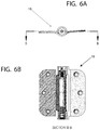
- FIG. 6A shows a side view of the device 10 while FIG. 6B shows a cross-sectional view taken along the line B-B which shows the different parts of the device shown in FIG. 5 in an assembled position.
- FIG. 7 is a perspective view of the device which is similar to the device shown in FIG. 5 .
- hinge plates 20 and 30 having associated knuckles 25 , 35 and 37 .
- Pin 70 is placed inside of knuckle 37 .
- Bendix Gear 62 is positioned adjacent to shaft 61 , and gear motor 40 and 60 which includes a motor 40 and a gear box 60 coupled to shaft 61 .
- Gear box 60 drives shaft 61 which drives Bendix drive shaft 62 , driving housing 63 , thereby driving drive dog 64 from an open position to a closed position.
- Drive dog 64 is fixed to a knuckle 37 via pin 70 .
- drive dog 64 when driven by housing 63 having teeth, it thereby causes plate 30 to rotate to a closed position thereby approaching plate 20 .
- the hinge when the hinge is coupled to a door and a respective door frame, it can be selectively triggered to close a door.
- a motor electrode pin 55 a Positioned adjacent to motor 40 is a motor electrode pin 55 a which is configured to be coupled to lower pivot pin housing 56 .
- a motor electrode pin 55 a Positioned adjacent to lower pivot pin housing is fuse ring 59 , an insulator cup 58 , batteries 52 and 54 , as well as a battery pre-load spring.
- An end cap 72 can be used to screw in and fasten batteries 52 and 54 into the pivot pin housing 56 .
- fuse ring 59 melts thereby causing batteries 52 and 54 to be driven axially towards the motor of the gear motor 40 thereby causing the batteries to be electrically connected to the gear motor 40 .
- This then causes the gear motor to be engaged and then to drive the rotatable portion of the gear motor to cause the hinge to rotate from a first position to a second position.
- FIG. 8A is an end view of the device while FIG. 8B is a side cross-sectional view of the device 10 A which is a modified view of the device shown in FIG. 7 .
- the hinge is in an armed position, with the fuse ring 59 separating the batteries from the gear motor.
- the Bendix gear is disconnected leaving the hinge free to pivot.
- FIG. 8C shows a side cross-sectional view of the device 10 A again wherein FIG. 8D shows the view taken along the line A-A.
- the fuse ring 59 has melted thereby driving via spring 57 batteries 52 and 54 up into gear motor 40 thereby creating an engagement of the device.
- gear motor 40 is activated and now powered by batteries 52 and 54 electrically coupling with gear motor 40 thereby driving hinge plate 30 into a closed position.
- FIG. 9 is a side view of another embodiment. This embodiment is similar to the embodiment of U.S. application Ser. No. 16/132,415 filed on Sep. 15, 2018.
- This view shows a further exploded view of the device which shows hinges 112 and 120 which shows hinge 112 having knuckles 114 and 116 with hole 117 in knuckle 116 . It also shows hinge 120 with knuckle 122 having groove 123 with angled section 124 and horizontal section 128 .
- first end section 143 a and a second opposite end section 143 b and a pin 146 there is a first end section 143 a and a second opposite end section 143 b and a pin 146 .
- a spring 150 is coupled to the body section 140 between the end sections 143 a and 143 b .
- Coupled to the main body 140 is a gear 160 .
- the gear 160 can be in any form however in at least one embodiment is in the form of a tapered worm gear or self-threading screw.
- locking pins 162 and 164 Disposed adjacent to worm gear 160 are locking pins 162 and 164 which fit inside of respective holes 117 on knuckle 116 .
- Positioned in a region of first section 143 a is a first set of bearings 142
- at the second end section 143 b are a second set of bearings 144 .
- End section 170 is shown with bushing 219 disposed adjacent to it.
- Bushing 219 is configured to fit inside of knuckle 116 and 122 .
- FIG. 10 is a side cross-sectional view of the hinge body and end section of a first embodiment.
- main body section 140 having cover 141 , spring 150 disposed inside cover 141 a bolt 152 having a threaded shaft section 154 , a main body section 163 of gear block 161 .
- Pin 146 is shown extending into main body section 163 , into hole 169 (See FIG. 6A ).
- Gear 160 is shown coupled to body section 163 , and is configured to receive drive pin 192 , particularly pointed section or tip 193 which inserts into a top section of gear 160 .
- Gear 160 fits inside of contoured section 167 of receiving bushing 166 .
- Gear block 161 receives the threaded section 154 of bolt 152 in threaded region 168 .
- receiving housing houses drive pin 192
- an electronically collapsible block 190 fits inside of section 175 of end section 170 .
- the electronically collapsible block can take the place of a fuse which then allows the drive pin 192 to slide up under pressure from spring 150 which then allows the gear 160 to be engaged and to selectively open or close the hinge.
- an additional block 199 which includes a transceiver for wireless communication and a power pack comprising a battery.
- the selectively collapsible block can comprise a solenoid which collapses on itself which shrinks the block on itself to selectively shrink the size of the block to allow the gear to 160 to be engaged.
- FIG. 11A is a side transparent view of an electronic cap 201 which houses a controller 202 which is essentially the components of controller 100 but disposed inside of housing or cap 201 .
- Cap 201 is coupled to housing or end section 170 .
- Controller 202 is coupled to a heating element 203 which when triggered by controller 202 heats up fuse 206 so that fuse link 206 that dissolves through passage 207 or otherwise intentionally fails and then causes the spring such as spring 150 to expand driving gear 160 to mesh with adjacent gearing or contoured section 167 to drive or actuate the hinge.
- FIG. 11A is a side transparent view of an electronic cap 201 which houses a controller 202 which is essentially the components of controller 100 but disposed inside of housing or cap 201 .
- Cap 201 is coupled to housing or end section 170 .
- Controller 202 is coupled to a heating element 203 which when triggered by controller 202 heats up fuse 206 so that fuse link 206 that dissolves through passage 207 or otherwise intentionally fails and then causes the spring such
- controller 202 is coupled via wire 203 a to a solenoid 209 which is disposed inside of housing or end section 170 , wherein solenoid 209 is configured to collapse, thereby allowing spring 150 to expand and rotate, causing gear 160 to mesh with contoured section 167 thereby actuating the hinge.
- FIG. 12A is a side cross-sectional view of the embodiment 210 with the hinges 112 and 120 removed while FIG. 12B shows a side cross-sectional view of the second embodiment 210 a with the hinges 112 and 120 removed.
- End cap 201 which is coupled to housing or end section 170 .
- End cap includes a controller 217 which is essentially controller 100 disposed inside of end cap 201 .
- Controller 217 is electrically coupled to heating element 196 .
- Heating element 196 is configured to be selectively heated by controller 217 to collapse a heatable fuse or collapsible block 190 .
- heatable fuse or collapsible block 190 When heatable fuse or collapsible block 190 is heated it collapses allowing drive pin 192 to be forced up by spring 150 thereby causing gear 160 to mesh with contoured section 167 to actuate the hinge.
- this embodiment includes a head section 170 and a body section 140 .
- the head section 170 includes the drive pin 192 and the electronically collapsible block 190 .
- spring 180 is also shown as well as receiving element 166 .
- Gear 160 is shown prior to full engagement with the contoured section 167 of receiving element 166 .
- Gear 160 includes opening 160 a to receive tip 193 of drive pin 192 or bearing cap 160 a of frangible bulb 211 .
- Bearings 144 are shown positioned adjacent to gear block 161 while pin 146 is shown coupled to gear body 161 as well.
- Tapered end section 168 has a hollowed out and internally threaded section 168 a which is left hollow by the removal of bolt 152 (see FIG. 10 ).
- Spring 150 is shown which is coupled at one end to tapered end section 68 of the gear, while the opposite end is coupled to block 149 as described above.
- Bearings 142 are shown while positioned between cover 141 and end block 149 .
- End block 149 includes a hollowed-out section 149 a which is hollow to receive bolt 152 (See FIG. 10 ).
- Collapsible shaft 211 includes bearing surface 216 and is inserted into block 215 which extends down from end section 170 . Block 215 and bearing surface 216 encases the collapsible shaft or frangible bulb 211 such that when it is compromised, remnants are contained within.
- the frangible bulb can be collapsed either through ambient heat or through the heating of a heating element 197 which when controlled by controller 217 heats the frangible bulb above a collapse temperature to cause the frangible bulb to collapse.
- Additional bearings 144 and 142 are shown with bearings 144 being formed as disc bearings. Bearings 142 are also formed as disc bearings as well.
- a microphone 212 coupled to the end cap is a microphone 212 , a loudspeaker 213 , and an indicator light. Loudspeaker 213 or indicator light 214 can also be referred to as an annunciator.
- Microphone 212 is configured to receive audible instructions for selectively activating the hinge
- loudspeaker 213 is configured to convey information to parties near the hinge
- indicator light is configured to provide visual indication of activation of the hinge.
- FIGS. 13 A and 13 B show different embodiments than FIGS. 12A and 12B in that FIG. 13A discloses a collapsible block 290 which comprises a solenoid which is configured to selectively collapse when instructed by controller 217 .
- a different collapsible block 291 which is also driven by a solenoid and controlled by controller 217 can be instructed to collapse as well. This then causes gear 160 to be driven by spring 150 (not shown) to cause engagement of gear 160 into contoured section 167 to cause activation of the hinge which results in either selective closure or opening of the hinge.
- FIG. 13C shows another embodiment which shows controller 217 configured to drive a motor 230 which actuates a locking pin 231 .
- controller 217 configured to drive a motor 230 which actuates a locking pin 231 .
- motor 230 actuates locking pin 231 , this draws locking pin into motor thereby clearing a path for an upward movement of block 293 allowing a spring such as spring 150 (See FIG. 9 ) to drive the block 293 upward thereby allowing for the engagement of gear 160 and the actuation of the hinge.
- FIGS. 14 and 15 are a side view of knuckle 122 which includes groove 123 having angled section 124 , angle point 126 extending section 128 and an end 129 .
- the movement of a pin such as pin 146 relative to knuckle 122 is first from point 224 up along angled section 124 in the direction of arrow 222 , once the pin 146 reaches an angle point such as angle point 126 , knuckle 122 is driven in radial manner along a curve path in the direction of arrow 223 . This causes end 129 to move from a first position to a second position.
- the temperature at which the fuse or the frangible bulb becomes compromised could be any suitable elevated temperature which would indicate an extreme situation such as a fire.
- the elevated temperature could be at least 120 degrees F., 130 degrees F., 140 degrees F. or any other suitable temperature.
- the angled rotational movement of pin 46 signifies the angled (partially axially) rotational movement of the gear 160 enmeshing with the contoured region 167 as well.
- the hinge 112 when pin 146 is in position 224 , the hinge 112 is in a position wherein the spring is coiled but the hinge 112 is disengaged, with gear 160 not engaged with contoured section 167 , this thereby allows the hinge and by extension the door to swing freely.
- the angled section 124 of the groove 123 forms a block or a lock that keeps the knuckle from rotating relative to the pin 146 , by the substantially vertical extension of groove 123 when the hinge is installed.
- end 150 . 2 of spring 150 is now fixed to hinge 112
- end 150 . 1 of spring 150 which is coupled to surface 149 b (See FIG. 10 ) causes spring torsion to be exerted between hinges 112 and 120 .
- pin 147 is coupled to knuckle 122 , this drives knuckle 122 to rotate and thereby actuate the door.
- further uncoiling of spring 150 results in knuckle 122 rotating as shown by arrow 223 from a first position to a final position along rotational path 223 thereby actuating the door.
- frangible bulb or collapsible shaft 211 is used instead of fuse or collapsible block 190 and drive pin 92 .
- the movement is therefore similar to that described above.
- FIG. 16 shows another alternative embodiment which shows hinges 120 and 130 coupled together.
- Hinge 120 has knuckle 125 which has an angled slot 129 a disposed therein. This angled slot 129 a is similar to that disclosed above.
- Hinge 130 has knuckles 135 and 137 .
- There is an electronic drive comprising two separate blocks 240 and 242 which create a drive that is upward driving worm gear 160 up along with a pin that resides inside of slot 129 a .
- the upward drive motion created by a solenoid drive or motor driven worm gear disposed inside of blocks 242 and 240 results in these blocks separating and driving pin 261 and gear 262 upward into worm gear 160 . This drives worm gear 160 up in an upward rotating motion.
- Worm Gear 160 then locks with corresponding gear 264 disposed in knuckle 137 .
- Gear 264 is locked via pin 270 in knuckle 137 .
- This locking causes the drive comprising drive blocks 240 and 242 to drove hinge 130 to rotate vs hinge 120 to either open or close the hinge.
- the drive 241 comprising drive blocks 240 and 242 can be powered by a transceiver block and power block 255 housed in a lower housing 256 . Inside of lower housing are also batteries 254 and/or 252 which are secured by a screw 250 . Alternatively. Transceiver and power block 255 is also configurable to receive direct electrical wiring as well. Transceiver and power block 255 is configured to communicate with the network shown in FIG. 4 .
Abstract
Description
Claims (6)
Priority Applications (1)
| Application Number | Priority Date | Filing Date | Title |
|---|---|---|---|
| US16/255,739 US11072964B2 (en) | 2018-01-23 | 2019-01-23 | Compact hinge actuating device |
Applications Claiming Priority (3)
| Application Number | Priority Date | Filing Date | Title |
|---|---|---|---|
| US201862620976P | 2018-01-23 | 2018-01-23 | |
| US16/132,415 US11053722B2 (en) | 2017-09-15 | 2018-09-15 | Selectively closable hinge |
| US16/255,739 US11072964B2 (en) | 2018-01-23 | 2019-01-23 | Compact hinge actuating device |
Related Parent Applications (1)
| Application Number | Title | Priority Date | Filing Date |
|---|---|---|---|
| US16/132,415 Continuation-In-Part US11053722B2 (en) | 2017-09-15 | 2018-09-15 | Selectively closable hinge |
Publications (2)
| Publication Number | Publication Date |
|---|---|
| US20190390503A1 US20190390503A1 (en) | 2019-12-26 |
| US11072964B2 true US11072964B2 (en) | 2021-07-27 |
Family
ID=68980569
Family Applications (1)
| Application Number | Title | Priority Date | Filing Date |
|---|---|---|---|
| US16/255,739 Active US11072964B2 (en) | 2018-01-23 | 2019-01-23 | Compact hinge actuating device |
Country Status (1)
| Country | Link |
|---|---|
| US (1) | US11072964B2 (en) |
Cited By (6)
| Publication number | Priority date | Publication date | Assignee | Title |
|---|---|---|---|---|
| US20190376332A1 (en) * | 2018-06-06 | 2019-12-12 | Richard Chi-Hsueh | Hinge system of electric door |
| US20200131824A1 (en) * | 2018-10-31 | 2020-04-30 | JKO Improvements LLC | Automatic Emergency Door Closure |
| US20200224482A1 (en) * | 2017-04-25 | 2020-07-16 | Life Door, Inc. | Door closing device |
| US11434682B2 (en) * | 2018-03-30 | 2022-09-06 | Masonite Corporation | Compact door closer |
| US11549296B2 (en) * | 2018-11-07 | 2023-01-10 | J. D. Bucklin | Temperature activated door spring |
| US11879287B2 (en) | 2017-04-25 | 2024-01-23 | Masonite Corporation | Door closing device |
Families Citing this family (7)
| Publication number | Priority date | Publication date | Assignee | Title |
|---|---|---|---|---|
| US11174664B2 (en) | 2018-03-20 | 2021-11-16 | Masonite Corporation | Door positioning system |
| US11885166B2 (en) * | 2019-11-06 | 2024-01-30 | Upton Ventures, Inc. | Condition activated door spring |
| US11208839B2 (en) * | 2020-03-03 | 2021-12-28 | Gmi Holdings, Inc. | Space venting upward acting door system and method |
| CN111441685A (en) * | 2020-04-09 | 2020-07-24 | 智慧式有限公司 | Novel hinge for automatically controlling opening and closing of door |
| CN111535719B (en) * | 2020-05-18 | 2021-03-02 | 广州成呈智能科技有限公司 | Safety anti-overflow door of poison gas induction device |
| US11719035B2 (en) * | 2020-09-09 | 2023-08-08 | Joseph M. Schulz | Non-contact, automatic door hinge operator system |
| US20220364405A1 (en) * | 2021-05-13 | 2022-11-17 | Rob J. Evans | Thermal-sensing fire door |
Citations (30)
| Publication number | Priority date | Publication date | Assignee | Title |
|---|---|---|---|---|
| US2520536A (en) * | 1948-08-16 | 1950-08-29 | Feeley Nelson | Door hinge |
| US2591476A (en) * | 1945-10-09 | 1952-04-01 | Alfred J Swanson | Hinged closure control |
| US3559232A (en) * | 1969-03-21 | 1971-02-02 | Rixson Inc | Electrically actuated door holder with manual opening and closing override, and automatic release to effect closure |
| US3699608A (en) * | 1970-10-23 | 1972-10-24 | Sooner Door Hardware Mfg Co | Automatic door closer |
| US3777423A (en) * | 1972-01-07 | 1973-12-11 | Rixson Inc | Condition responsive door holder-closer |
| US3905063A (en) * | 1972-01-07 | 1975-09-16 | Rixson Firemark | Condition responsive door holder-closer |
| US3908309A (en) * | 1972-01-07 | 1975-09-30 | Rixson Firemark | Particulate products of combustion detector for closure frame |
| US4102013A (en) * | 1976-12-13 | 1978-07-25 | Lawrence Brothers, Inc. | Tamper-proof spring hinge |
| US4339845A (en) * | 1978-05-09 | 1982-07-20 | Lawrence Brothers, Inc. | Spring hinge |
| US4583262A (en) * | 1984-08-20 | 1986-04-22 | C. Hager & Sons Hinge Manufacturing Company | Spring hinge |
| US4726613A (en) * | 1986-03-03 | 1988-02-23 | Best Lock Corporation | Fire safety door latch |
| US5058236A (en) * | 1990-02-06 | 1991-10-22 | Henson Ormel W | Adjustable hinge |
| US5121950A (en) * | 1991-04-23 | 1992-06-16 | The Stanley Works | Heat activated spring loaded locking bolt for hinged doors and door assemblies employing same |
| US5652563A (en) * | 1995-11-01 | 1997-07-29 | Maus; Andrew B. | Safety system for a horse stable |
| US5864920A (en) * | 1994-04-25 | 1999-02-02 | Schlage Lock Company | Door closer for the non-fire side of a fire-door safety installation |
| US6481160B1 (en) * | 1999-02-04 | 2002-11-19 | The Stanley Works | Axial door operator |
| US7367161B1 (en) * | 2004-04-30 | 2008-05-06 | Michael Wayne Jones | Gate opening and closing apparatus |
| US8169169B2 (en) * | 2005-04-13 | 2012-05-01 | Brian Hass | Door operator for controlling a door and method of same |
| US8375519B1 (en) * | 2009-07-27 | 2013-02-19 | Darrell Glenn Cooper | Signal activated door hinge |
| US20130205670A1 (en) * | 2012-01-23 | 2013-08-15 | Ultra Aluminum Manufacturing, Inc. | Apparatus for opening and closing a barrier |
| US8955194B2 (en) * | 2009-01-20 | 2015-02-17 | Jeffrey M. Teta | Fire door hinge with fusible pin |
| US20170292308A1 (en) * | 2016-04-12 | 2017-10-12 | Mark A. Beran | Control System for Self Restoring Doors, Gates and Windows |
| US20180283078A1 (en) * | 2017-03-28 | 2018-10-04 | Erosh Damboragama | Motorized door hinge system and method |
| US20180305969A1 (en) * | 2017-04-25 | 2018-10-25 | Life Door, Inc. | Emergency door closing device |
| US20190330903A1 (en) * | 2016-12-27 | 2019-10-31 | Locinox | Hydraulically damped, self closing hinge |
| US20190376332A1 (en) * | 2018-06-06 | 2019-12-12 | Richard Chi-Hsueh | Hinge system of electric door |
| US10626651B2 (en) * | 2015-12-10 | 2020-04-21 | Jong Bok CHANG | Hinge for opening/closing door |
| US20200173213A1 (en) * | 2018-11-07 | 2020-06-04 | J.D. Bucklin | Temperature activated door spring |
| US20200177051A1 (en) * | 2017-07-13 | 2020-06-04 | Panasonic Intellectual Property Management Co., Ltd. | Hinge device and electric power system |
| US20210025215A1 (en) * | 2018-03-30 | 2021-01-28 | Masonite Corporation | Compact door closer |
-
2019
- 2019-01-23 US US16/255,739 patent/US11072964B2/en active Active
Patent Citations (34)
| Publication number | Priority date | Publication date | Assignee | Title |
|---|---|---|---|---|
| US2591476A (en) * | 1945-10-09 | 1952-04-01 | Alfred J Swanson | Hinged closure control |
| US2520536A (en) * | 1948-08-16 | 1950-08-29 | Feeley Nelson | Door hinge |
| US3559232A (en) * | 1969-03-21 | 1971-02-02 | Rixson Inc | Electrically actuated door holder with manual opening and closing override, and automatic release to effect closure |
| US3699608A (en) * | 1970-10-23 | 1972-10-24 | Sooner Door Hardware Mfg Co | Automatic door closer |
| US3777423A (en) * | 1972-01-07 | 1973-12-11 | Rixson Inc | Condition responsive door holder-closer |
| US3905063A (en) * | 1972-01-07 | 1975-09-16 | Rixson Firemark | Condition responsive door holder-closer |
| US3908309A (en) * | 1972-01-07 | 1975-09-30 | Rixson Firemark | Particulate products of combustion detector for closure frame |
| US4141123A (en) * | 1976-12-13 | 1979-02-27 | Lawrence Brothers, Inc. | Method of manufacturing a spring hinge |
| US4102013A (en) * | 1976-12-13 | 1978-07-25 | Lawrence Brothers, Inc. | Tamper-proof spring hinge |
| US4339845A (en) * | 1978-05-09 | 1982-07-20 | Lawrence Brothers, Inc. | Spring hinge |
| US4583262A (en) * | 1984-08-20 | 1986-04-22 | C. Hager & Sons Hinge Manufacturing Company | Spring hinge |
| US4726613A (en) * | 1986-03-03 | 1988-02-23 | Best Lock Corporation | Fire safety door latch |
| US5058236A (en) * | 1990-02-06 | 1991-10-22 | Henson Ormel W | Adjustable hinge |
| US5121950A (en) * | 1991-04-23 | 1992-06-16 | The Stanley Works | Heat activated spring loaded locking bolt for hinged doors and door assemblies employing same |
| US5864920A (en) * | 1994-04-25 | 1999-02-02 | Schlage Lock Company | Door closer for the non-fire side of a fire-door safety installation |
| US5652563A (en) * | 1995-11-01 | 1997-07-29 | Maus; Andrew B. | Safety system for a horse stable |
| US6481160B1 (en) * | 1999-02-04 | 2002-11-19 | The Stanley Works | Axial door operator |
| US7367161B1 (en) * | 2004-04-30 | 2008-05-06 | Michael Wayne Jones | Gate opening and closing apparatus |
| US8169169B2 (en) * | 2005-04-13 | 2012-05-01 | Brian Hass | Door operator for controlling a door and method of same |
| US8955194B2 (en) * | 2009-01-20 | 2015-02-17 | Jeffrey M. Teta | Fire door hinge with fusible pin |
| US8375519B1 (en) * | 2009-07-27 | 2013-02-19 | Darrell Glenn Cooper | Signal activated door hinge |
| US20130205670A1 (en) * | 2012-01-23 | 2013-08-15 | Ultra Aluminum Manufacturing, Inc. | Apparatus for opening and closing a barrier |
| US10626651B2 (en) * | 2015-12-10 | 2020-04-21 | Jong Bok CHANG | Hinge for opening/closing door |
| US20170292308A1 (en) * | 2016-04-12 | 2017-10-12 | Mark A. Beran | Control System for Self Restoring Doors, Gates and Windows |
| US20190330903A1 (en) * | 2016-12-27 | 2019-10-31 | Locinox | Hydraulically damped, self closing hinge |
| US20180283078A1 (en) * | 2017-03-28 | 2018-10-04 | Erosh Damboragama | Motorized door hinge system and method |
| US20180305969A1 (en) * | 2017-04-25 | 2018-10-25 | Life Door, Inc. | Emergency door closing device |
| US20200224482A1 (en) * | 2017-04-25 | 2020-07-16 | Life Door, Inc. | Door closing device |
| US10808447B2 (en) * | 2017-04-25 | 2020-10-20 | Masonite Corporation | Emergency door closing device |
| US20210032923A1 (en) * | 2017-04-25 | 2021-02-04 | Masonite Corporation | Emergency door closing device |
| US20200177051A1 (en) * | 2017-07-13 | 2020-06-04 | Panasonic Intellectual Property Management Co., Ltd. | Hinge device and electric power system |
| US20210025215A1 (en) * | 2018-03-30 | 2021-01-28 | Masonite Corporation | Compact door closer |
| US20190376332A1 (en) * | 2018-06-06 | 2019-12-12 | Richard Chi-Hsueh | Hinge system of electric door |
| US20200173213A1 (en) * | 2018-11-07 | 2020-06-04 | J.D. Bucklin | Temperature activated door spring |
Cited By (11)
| Publication number | Priority date | Publication date | Assignee | Title |
|---|---|---|---|---|
| US20200224482A1 (en) * | 2017-04-25 | 2020-07-16 | Life Door, Inc. | Door closing device |
| US11428039B2 (en) * | 2017-04-25 | 2022-08-30 | Masonite Corporation | Emergency door closing device |
| US20220403692A1 (en) * | 2017-04-25 | 2022-12-22 | Masonite Corporation | Emergency door closing device |
| US11608670B2 (en) * | 2017-04-25 | 2023-03-21 | Masonite Corporation | Door closing device |
| US11713610B2 (en) * | 2017-04-25 | 2023-08-01 | Masonite Corporation | Emergency door closing device |
| US11879287B2 (en) | 2017-04-25 | 2024-01-23 | Masonite Corporation | Door closing device |
| US11434682B2 (en) * | 2018-03-30 | 2022-09-06 | Masonite Corporation | Compact door closer |
| US20190376332A1 (en) * | 2018-06-06 | 2019-12-12 | Richard Chi-Hsueh | Hinge system of electric door |
| US11639625B2 (en) * | 2018-06-06 | 2023-05-02 | Richard Chi-Hsueh | Hinge system of electric door |
| US20200131824A1 (en) * | 2018-10-31 | 2020-04-30 | JKO Improvements LLC | Automatic Emergency Door Closure |
| US11549296B2 (en) * | 2018-11-07 | 2023-01-10 | J. D. Bucklin | Temperature activated door spring |
Also Published As
| Publication number | Publication date |
|---|---|
| US20190390503A1 (en) | 2019-12-26 |
Similar Documents
| Publication | Publication Date | Title |
|---|---|---|
| US11072964B2 (en) | Compact hinge actuating device | |
| US10597928B2 (en) | Barrier operator feature enhancement | |
| US9818243B2 (en) | System interaction with a movable barrier operator method and apparatus | |
| US20130276488A1 (en) | Motor driven lock for truck door | |
| CN103930636B (en) | Lock system | |
| US20150275564A1 (en) | Garage door operator accessory | |
| WO2007111833A2 (en) | Alarm actuated pet door lock releasemechanism | |
| US5243325A (en) | Latch gate alarm switch assembly | |
| US10344523B2 (en) | Opposing door opener | |
| US7148798B2 (en) | Gate closing timer for security gate override system | |
| KR100517437B1 (en) | Self-closing device for fire door | |
| JP4404206B2 (en) | Electric door closer | |
| CN202627778U (en) | Electric garage door wireless distant-control system with time delay closing and warning functions | |
| CN205445284U (en) | Intelligence house monitor control system | |
| EP2613299B1 (en) | Alarm system for windows and doors | |
| CN215293771U (en) | Fireproof check valve assembly | |
| CN2584778Y (en) | Anti-theft door and safety alarm device | |
| KR100517438B1 (en) | Self-closing device for fire door | |
| JP2006097245A (en) | Anticrime ventilation window system | |
| KR200373543Y1 (en) | Burglar alarm | |
| KR19990078481A (en) | Wireless door lock | |
| US319053A (en) | Electric burglar-alarm | |
| US773650A (en) | Burglar-alarm. | |
| FR3071952A1 (en) | AUTONOMOUS AUTOMATIC ALARM FOR CARPENTRY | |
| WO2016171943A1 (en) | Hinge sensor for barrier |
Legal Events
| Date | Code | Title | Description |
|---|---|---|---|
| FEPP | Fee payment procedure |
Free format text: ENTITY STATUS SET TO UNDISCOUNTED (ORIGINAL EVENT CODE: BIG.); ENTITY STATUS OF PATENT OWNER: SMALL ENTITY |
|
| FEPP | Fee payment procedure |
Free format text: ENTITY STATUS SET TO SMALL (ORIGINAL EVENT CODE: SMAL); ENTITY STATUS OF PATENT OWNER: SMALL ENTITY |
|
| STPP | Information on status: patent application and granting procedure in general |
Free format text: DOCKETED NEW CASE - READY FOR EXAMINATION |
|
| STPP | Information on status: patent application and granting procedure in general |
Free format text: NON FINAL ACTION MAILED |
|
| STPP | Information on status: patent application and granting procedure in general |
Free format text: RESPONSE TO NON-FINAL OFFICE ACTION ENTERED AND FORWARDED TO EXAMINER |
|
| STPP | Information on status: patent application and granting procedure in general |
Free format text: NOTICE OF ALLOWANCE MAILED -- APPLICATION RECEIVED IN OFFICE OF PUBLICATIONS |
|
| AS | Assignment |
Owner name: CEASEFIRE DOOR HINGE INC., NEW YORK Free format text: ASSIGNMENT OF ASSIGNORS INTEREST;ASSIGNORS:TETA, JEFFREY MICHAEL;PALUMBO, KEITH ANDREW;DITTRICH, JOSHUA VAUGHN;SIGNING DATES FROM 20190628 TO 20200212;REEL/FRAME:056398/0716 Owner name: TETA, JEFFREY MICHAEL, NORTH CAROLINA Free format text: ASSIGNMENT OF ASSIGNORS INTEREST;ASSIGNOR:CEASEFIRE DOOR HINGE, INC.;REEL/FRAME:056398/0772 Effective date: 20210528 |
|
| STPP | Information on status: patent application and granting procedure in general |
Free format text: PUBLICATIONS -- ISSUE FEE PAYMENT RECEIVED |
|
| STPP | Information on status: patent application and granting procedure in general |
Free format text: PUBLICATIONS -- ISSUE FEE PAYMENT VERIFIED |
|
| STCF | Information on status: patent grant |
Free format text: PATENTED CASE |