US11071057B2 - Energy control devices and methods for energy management in a transmission site of a wireless communication network - Google Patents
Energy control devices and methods for energy management in a transmission site of a wireless communication network Download PDFInfo
- Publication number
- US11071057B2 US11071057B2 US16/321,861 US201616321861A US11071057B2 US 11071057 B2 US11071057 B2 US 11071057B2 US 201616321861 A US201616321861 A US 201616321861A US 11071057 B2 US11071057 B2 US 11071057B2
- Authority
- US
- United States
- Prior art keywords
- transmission
- power
- site
- energy
- electricity consumption
- Prior art date
- Legal status (The legal status is an assumption and is not a legal conclusion. Google has not performed a legal analysis and makes no representation as to the accuracy of the status listed.)
- Active, expires
Links
Images


Classifications
-
- H—ELECTRICITY
- H04—ELECTRIC COMMUNICATION TECHNIQUE
- H04W—WIRELESS COMMUNICATION NETWORKS
- H04W52/00—Power management, e.g. TPC [Transmission Power Control], power saving or power classes
- H04W52/02—Power saving arrangements
- H04W52/0203—Power saving arrangements in the radio access network or backbone network of wireless communication networks
- H04W52/0206—Power saving arrangements in the radio access network or backbone network of wireless communication networks in access points, e.g. base stations
-
- Y—GENERAL TAGGING OF NEW TECHNOLOGICAL DEVELOPMENTS; GENERAL TAGGING OF CROSS-SECTIONAL TECHNOLOGIES SPANNING OVER SEVERAL SECTIONS OF THE IPC; TECHNICAL SUBJECTS COVERED BY FORMER USPC CROSS-REFERENCE ART COLLECTIONS [XRACs] AND DIGESTS
- Y02—TECHNOLOGIES OR APPLICATIONS FOR MITIGATION OR ADAPTATION AGAINST CLIMATE CHANGE
- Y02D—CLIMATE CHANGE MITIGATION TECHNOLOGIES IN INFORMATION AND COMMUNICATION TECHNOLOGIES [ICT], I.E. INFORMATION AND COMMUNICATION TECHNOLOGIES AIMING AT THE REDUCTION OF THEIR OWN ENERGY USE
- Y02D30/00—Reducing energy consumption in communication networks
- Y02D30/70—Reducing energy consumption in communication networks in wireless communication networks
Definitions
- the presented technology relates to energy control devices and methods for energy management in a transmission site of a wireless communication network
- FIG. 1 is a block diagram schematically illustrating a wireless telecommunications system power fed by an external power grid according to prior art.
- the wireless telecommunications system comprises a network comprising transmissions sites, such as Radio Base Stations, RBSs, sites 20 .
- a site is controlled by a physical RBS serving macro and/or small cells (herein areas limited by dashed lines).
- a cell is an area in which an RBS is capable of supporting wireless radio communication, i.e. radio traffic, with a Mobile Terminal, MT 25 .
- Each RBS site 20 , 20 A, 20 B is electrically powered from an external power feed, e.g. an AC (Alternating Current) power grid or other energy source.
- each RBS 30 is connected to an external power feed 10 .
- RBS 30 in site 20 is connected to the external power feed 10 A: 1 via a power input connection 12 which may be an electric power cable.
- a power input connection 12 which may be an electric power cable.
- Other RBSs in nearby sites 20 A, 20 B are connected in the same way via an electric power cable 12 to the same power feed or another power feed 10 A: 2 operated by another power supplier than the first RBS site 20 .
- power feeds indicated as 10 A: 1 and 10 A: 2 may be the same power grid.
- the AC grid transmission lines are located around the country.
- the RBS nodes are located in different areas/cities, and are powered via (transformer) substations via the power transmission lines.
- a radio or transmission site node comprises a RBS 30 with at least one antenna and transceiver unit 62 providing wireless access for MTs 25 to the node within the site 20 B by means of any standardized Radio Access Technology, RAT, e.g. GSM (Global System for Mobile telecommunication), 3G (Third Generation), 4G (Forth Generation), LTE (Long Term Evolution), enhanced LTE, LTE advanced, 5G etc.
- RAT Radio Access Technology
- RBS sites indicated 20 and 20 A are macro sites.
- RBS site indicated 20 B is managing and controlling a small, or micro, cell structure only.
- RBS sites 20 , 20 A are therefore denoted RBS macro cell sites, and
- RBS site 20 B is denoted RBS micro cell site.
- the micro/small cell site 20 B comprises an RBS 30 B.
- a micro or small cell may cover a smaller part of a macro cell in a RBS macro cell site.
- the RBSs 30 , 30 B are capable of signalling and exchanging information messages via standardized protocols, e.g. at handover procedures.
- the RBSs of said cells exchange information to initiate and finalize such a handover procedure.
- the communication paths 22 between the RBSs are indicated by dash-dot arrows for indicating bi-directional communication.
- a wireless access network comprises often a plurality of RBSs.
- An RBS or RBS site may be owned by one party, e.g. a tower owner, and the equipment therein leased to at least one tenant, such as operator company.
- the tenants offer wireless radio access for different users and their wireless devices.
- RBS Energy Measurement Units
- An RBS may therefore comprise at least one EMU for each tenant.
- An operator must therefore organize and arrange the EMUs in the RBS to be able to measure each tenant's energy consumption in a way enabling fair charging for each tenant's energy consumption.
- the business model may be further complicated if an RBS is supplied from different electric energy sources beside the grid, such as Wind, Solar Cells, electric generators driven by any fuel, such as gas, diesel, etc.
- a method, and embodiments thereof for estimating electricity consumption E TOT during one or more transmission intervals of a transmission site or part of a transmission site comprises an associated scheduler for scheduling assignments during said one or more transmission intervals, and a set of radio transmitters having radio efficiency ⁇ r .
- Said method comprising a step of estimating scheduled transmission electricity consumption E tr,TOT based on a quotient of a sum P sch,sum of scheduled radio transmission powers P sch and the radio efficiency ⁇ r .
- an energy control device for estimating electricity consumption E TOT during one or more transmission interval of a transmission site or part of a transmission site.
- the site comprises an associated scheduler for scheduling assignments and a set of radio transmitters having radio efficiency ⁇ r .
- the device comprises a processor in a processing circuitry being operative to estimate scheduled transmission electricity consumption E tr,TOT based on a quotient of a sum P sch,sum of scheduled radio transmission powers P sch and the radio efficiency ⁇ r .
- FIG. 1 is a block diagram schematically illustrating a wireless telecommunications system according to prior art
- FIG. 2 is a block diagram illustrating an example of a transmission site power management system architecture
- FIG. 3 is a block diagram illustrating an alternative solution of a transmission site power management system
- FIG. 4 is flowchart of a method S 100 for estimating electricity consumption E TOT ;
- FIG. 5 is flowchart of another embodiment of the method S 100 ;
- FIG. 6 is flowchart of an embodiment of the method S 150 for calculating a tenant's site electricity consumption share
- FIG. 7 is a block diagram illustrating an energy control device capable of performing the method S 100 ;
- FIG. 8 is a block diagram of a transmission site in which devices and methods described herein may be implemented.
- FIG. 9 is a block diagram illustrating an example of a transmission site power management system architecture
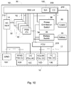
- FIG. 10 is a block diagram illustrating an alternative solution of a transmission site power management system
- FIG. 11 is flowchart of an embodiment S 160 of the method S 100 ;
- FIG. 12 is an example of an energy source table
- FIG. 13 is flowchart of another embodiment S 160 of the method S 100 ;
- FIG. 14 is flowchart of another embodiment S 160 of the method S 100 ;
- FIG. 15 is a diagram of energy consumption per transmission time interval, TTI.
- FIG. 16 is a block diagram illustrating an energy control device capable of performing the method S 160 and embodiments thereof.
- electricity consumption for radio transmission in a radio base station site is estimated based on scheduler data. Past consumption as well as scheduled future consumption may be estimated.
- FIG. 2 is a block diagram illustrating an example of a transmission site power management system architecture.
- the transmission site such as RBS, comprises either an eNodeB of a Long Term Evolution (LTE) system, Radio Network Controller (RNC) of a Third Generation (3G) system, Base Station Controller (BSC) of a Global System for Mobile Communication (GSM or 2G) or a Baseband Unit of a Fifth Generation (5G) system or possibly a combination of one or more of these.
- LTE Long Term Evolution
- RNC Radio Network Controller
- BSC Base Station Controller
- GSM or 2G Global System for Mobile Communication
- 5G Fifth Generation
- RBS controller 50 which comprises at least one processor circuitry of digital processors and supporting memory storages for storing computer software and processing data.
- RBS controller 50 comprises at least one processor circuitry of digital processors and supporting memory storages for storing computer software and processing data.
- different functions of a RBS are implemented, such as e.g. handover of mobile terminals between different RBS sites, communication with the mobile stations and a backbone of the RBS enabling communication with different nodes in the Internet, control of different functional blocks or units in the RBS, etc.
- Some functions may be implemented as hardware.
- the RBS comprises a number of digital buses 52 connected to the functions blocks and units.
- said function blocks and units consume electric power and could therefore be considered as loads 60 .
- said loads are radio stages R 1 , R 2 , R 3 , comprising transceivers (transmitters/receivers), power amplifier circuits and antennas ( 60 in FIG. 1 ).
- the power feeding of said function blocks or units are provided by a power management system comprising a power distribution system.
- Said power distribution system comprises one or a plurality of power feed circuits or power supply units (PSUs) also sometimes denoted as chargers 40 .
- PSUs power feed circuits or power supply units
- a PSU 40 may be designated for one or more function blocks and units.
- the PSUs 40 are connected to the external power feed, most probably an AC grid, via a power cable connection 12 via an AC input interface 32 , which may distribute different phases provided by the AC grid through connections to the input terminals 14 of the PSUs.
- the electricity supplied E tot,in may be measured at one or more power supply inputs and provided to the controller.
- the PSUs convert the AC power into DC which is distributed to the loads 60 via wiring 34 to power distribution switches 38 enabling to switch off and on the power to different loads 60 , i.e. functional blocks and units. Any disturbance in the external power feeding on connection 12 will propagate through the AC input interface 32 to the input terminals 14 of the PSUs 40 .
- the power management system is controlled by the RBS controller for controlling the power distribution system.
- the RBS is provided with an internal power feed 70 , e.g. an arrangement of batteries capacity adapted to provide enough power capacity to the RBS during a pre-set time of external power feed failure.
- a switch 36 is provided for connecting and disconnecting the power feeding from the internal power 70 .
- control buses 52 are connected between the RBS controller 50 and the functional blocks and units 40 , 36 , 38 , 60 enabling control by the RBS controller and two way communications with said functional blocks and units.
- a radio stage may be dedicated to serve only one of the tenants, e.g. R 1 is reserved for a tenant T 1 , while R 2 is dedicated to tenant T 2 , etc.
- R 1 is reserved for a tenant T 1
- R 2 is dedicated to tenant T 2
- the EMU is located in between the output of the power distribution switch and the corresponding Radio Stage serving a tenant.
- a stage may be adapted to operate according to a special Radio Access Technology, RAT. More than one tenant may be served by each stage.
- RAT Radio Access Technology
- Today's power system can measure energy via an EMU 80 connected to the transmission site (RBS/BTS), so called Energy meter.
- This energy meter is a bulky HW that needs to be mounted to every external power output from the Power Distribution Unit (PDU), to measure the specific power or measure bulk power for the specific tenant/operator on new or already installed base.
- PDU Power Distribution Unit
- the energy meter needs to be mounted in the cabinet system by a physical person on site. This requires extra site visit for installation.
- the Energy measure is used to differentiate the energy for the respective tenants/operator for correct billing of energy in use.
- the current solution with EMU requires separate HW to be installed on the telecom site or RBS, to measure energy for every tenants/operator.
- To measure energy consumption the solution need to be installed and be mounted in the cabinet or on site, and that requires a site visit and installation time.
- the already installed cabinets have no place for the extra HW, Energy meter that is installed for the bulky HW and need more installation time compared that with the new SW feature.
- the extra hardware may affect the system MTBF (mean time between failures) negatively.
- data from the radio scheduler can be used to provide a good estimate of electricity consumption if appropriately processed.
- the scheduler schedules assignments, e.g. data packets to be transmitted, and it determines the power to be radiated.
- a scheduling assignment is an allocation of particular downlink transmission resources to a user, e.g. a particular channel or particular OFDM subcarriers for a certain time.
- An example of a scheduling assignment is in the 3GPP 4G/LTE (Third generation Partnership Program fourth generation/Long Term Evolution) standard the allocation to a user of a particular resource in the PDSCH (Physical Downlink Shared Channel) resulting in the transmission of data to that user in the OFDM symbols and OFDM subcarriers making up the resource.
- the resource may be for example an LTE resource block of 12 subcarriers during 0.5 milliseconds.
- a decision on a scheduling assignment for a user typically also includes or implies a transmit power to use for that assignment. Hence, from scheduler data, the transmit power for a scheduling assignment can be determined.
- the information of an Energy per Resource Element value may be used; this value denotes the energy of an LTE resource element (one subcarrier during one OFDM symbol) as an average over all constellation points of the modulation scheme and before cyclic prefix insertion. This value may be summed for the resource elements comprised in the scheduling assignment. Optionally and for better accuracy, it may be adjusted (increased) to also account for the energy of the cyclic prefix.
- radio efficiency (which may be assumed to be constant, or for better accuracy be determined as a function of the total scheduled power)
- the radio efficiency can be used to determine the electricity consumption of the radio transmission, e.g. by dividing scheduled transmit power with the radio efficiency.
- radio electricity consumption per tenant may be determined.
- Other electricity consumption in the site may also be assigned to tenants based on scheduled radiated power, for example in proportion to scheduled radiated power.
- excess heat produced by the radio may also be determined: Based on knowledge of cooling system efficiency (e.g used electric energy for the cooling equipment per heat energy removed from the enclosure) it is possible to assign also electricity consumption for cooling to tenants.
- cooling system efficiency e.g used electric energy for the cooling equipment per heat energy removed from the enclosure
- electricity consumption for cooling may be determined based on operations data for the cooling system (e.g. duty cycle data such as on-time for fans) and then assigned to tenants in proportion to each tenants scheduled power or each tenants share of heat loss in radios or other equipment.
- operations data for the cooling system e.g. duty cycle data such as on-time for fans
- energy losses in PSUs may be determined from knowledge of PSU efficiency (e.g. assumed constant or varying in a known way with load) and assigned to tenants.
- scheduling is known some time in advance, by determining electricity consumption from scheduler data it will be possible to control the available energy sources continuously (for example to switch on or off PSUs to save on idling power consumption) to match the load without unnecessary excess capacity and thus improve energy efficiency.
- FIG. 3 is illustrating an alternative solution of a transmission site power management system.
- the architecture of the systems illustrated in FIGS. 2 and 3 are similar except that the EMUs 80 in the system in FIG. 2 are replaced by an energy control device CD 200 being a part of or associated with the RBS controller 50 .
- the power management system comprises said energy control device CD 200 and the power distribution system.
- the energy control device, the scheduler and other functionality of the site may be implemented by on-site hardware, but also wholly or partly as a cloud solution where functionality is executed in a cloud computing center.
- the basic principles of the invention remain the same regardless of where functionality is executed.
- the solution is based on the associated scheduler 100 , which is comprised in or associated (e.g. in a cloud architecture solution) with the transmission site or a part of the transmission site ( 20 in FIG. 1 ) and controls the data traffic transmission operation of the radio transmitters of a transmission site.
- the scheduler plans the radio traffic to be sent for a coming time interval based on radio traffic information.
- an energy control device or unit be in connection with the scheduler, said energy control device or unit calculates the needed power consumption condition for the coming time interval, it will be possible to measure the power consumption.
- the new method for energy meter does not require any HW to be installed.
- the new solution solves the problem that is raised in current installed cabinets, and does not require site visit.
- the method can be remotely downloaded to the transmission site.
- the method for estimating electricity consumption E TOT is based on the sum of the scheduled radio transmission power P sch,sum during a transmission interval and radio efficiency ⁇ r of at least one radio transmitter of the transmission site.
- the radio efficiency ⁇ r a known and fixed value of the radio efficiency may be used, e.g. an average value ⁇ r,avg based on the radio efficiency ⁇ r , of a number of radio transmitters of the transmission site.
- a measured value of the radio efficiency ⁇ r may be used.
- a radio transmission efficiency ⁇ r which is dependent of the total scheduled radio transmission power P sch,sum , i.e. ⁇ r [P sch,sum ], which will result in an improved accuracy of the estimation of electricity consumption E TOT .
- ⁇ r Based on the dependency between the radio transmission efficiency ⁇ r and the total scheduled radio transmission power P sch,sum , it is possible to find a relation between electricity consumption E TOT and radio transmission power P sch,sum . Said relation may be implied and expressed in a table, from which a value of the electricity consumption E TOT may be acquired for a value of the radio transmission power P sch,sum .
- a fixed value of the radio efficiency ⁇ r may be used during a transmission interval with time length TI, wherein the radio transmission power P sch,sum is not variating.
- the relevant ⁇ r is determined based on P sch,sum and electricity consumption is then determined based on scheduled power and ⁇ r .
- the relationship between P sch,sum and ⁇ r may be e.g. pre-measured and stored, or calculated according to a pre-determined mathematical relationship.
- FIG. 4 is flowchart of a method S 100 for estimating electricity consumption E TOT .
- FIG. 4 it is illustrated a method for estimating the electricity consumption E TOT during a transmission interval of a transmission site or part of a transmission site.
- the site comprises a scheduler for scheduling assignments using said transmission site, a set of radio transmitters having radio efficiency ⁇ r .
- Said method comprising a step of:
- the scheduled power P sch during transmission interval TI may be acquired from an energy per Resource Element value provided by the scheduler.
- the radio transmission of the scheduling assignments is here assumed to last for the duration of the transmission interval, TI. If transmission lasts only part of the interval, the power contribution from that scheduling assignment needs to be reduced in proportion.
- E TOT is the total power in watt and the radio efficiency ⁇ r is assumed to vary with P sch,sum
- E TOT here represents the total power in watts. If the right hand side of the equations is multiplied by the duration TI of the transmission interval, E TOT instead represents the total amount of energy consumed in watt-time units (e.g Joule or kWh). Thus, the total amount of electric energy consumption may be expressed as consumed energy or consumed power.
- Said total amount of electric energy consumption during a time period comprising one or more transmission intervals may be split into electric energy consumption for each tenant based on the number of scheduled assignments belonging to each of the tenants and the transmission power scheduled for each assignment during said time period.
- the electric energy consumption for each tenant may be estimated by adding the scheduled power P sch during each transmission interval during the time period and averaging, or by multiplying the scheduled power P sch with the transmission interval length TI and adding the energy consumption for each transmission interval of the time period.
- the scheduled power P sch may be fixed during a transmission interval according to some radio access standards, e.g. Long Term Evolution (LTE).
- LTE Long Term Evolution
- the scheduled power P sch is typically fixed during the time period of a half subframe.
- the scheduled power P sch during transmission interval may be acquired from an energy per Resource Element value provided by the scheduler.
- the radio efficiency ⁇ r As there is a relation between the radio transmission efficiency ⁇ r and the total scheduled radio transmission power P sch,sum .
- Said relation may be known by measurement for said radio transmitter design or pre-determined in another way and defined in a table for different values of the total scheduled radio transmission power P sch,sum .
- the transmitted power for reference signals, etc. e.g. used in systems operating according to LTE
- similar signaling may also be included in P sch,sum .
- P sch,sum By including the transmitted power for reference signals, etc. in P sch,sum , it may also be taken into account in summing the energy consumption, and possibly assigned to different tenants in proportion to the power of their scheduling assignments. Alternatively, it may be assigned in equal proportion to tenants, or assigned according to some other suitable ground.
- the power consumption of a particular tenant may for example be determined by dividing the sum of the power scheduled for that tenant by the sum of the power scheduled for all tenants and then multiplying by the total power consumption determined as above (which as explained above may include overhead such as power for reference signals, etc.), thus assigning the overhead power to tenants in proportion to scheduled power.
- the electric loss E Loss,tr in the set of radio transmitters may be calculated by determining by using an estimation of electricity loss E Loss,tr based on scheduled transmission electricity consumption E tr,TOT :
- E Loss,tr E tr,TOT *(1 ⁇ r )
- the electric loss E Loss,tr in the set of radio transmitters is determined by using an estimation of electricity loss E Loss,tr based on scheduled transmission electricity consumption E tr,TOT , i.e. the share of consumed electric power in the radio which is not radiated will become heat loss.
- power used for cooling is to be assigned to tenants, this may be made according to the radio transmitter electric loss caused by each tenant's scheduled power, e.g. in proportion to the scheduled power of each tenant.
- FIG. 5 is flowchart of another embodiment of the method S 100 for estimating electricity consumption E TOT .
- the method S 100 for estimating the electricity consumption E TOT during a transmission interval may further comprise the adding of the consumption of the site's power distribution system or part of the site's power distribution system. Then, the method may comprise the step of:
- E TOT E tr,TOT +E PDI
- the electricity consumption E PDI of the site's power distribution system during the same transmission interval may be calculated by using the step of:
- the electricity supplied E tot,in may be measured at one or more power supply inputs and provided to the controller.
- Another way of determining the electricity consumption of the power distribution system is to use a fixed efficiency figure, or an efficiency that is a function of the distributed power.
- the efficiency figure or function may e.g. be calculated from design data or pre-measured.
- the method S 100 comprising a method S 150 for calculating a tenant's site electricity consumption share.
- step S 110 following equation may therefore be used:
- Said total amount of electric energy consumption during a time period comprising one or more transmission intervals may be split into electric energy consumption for each tenant based on the number of scheduled assignments belonging to each of the tenants and the transmission power scheduled for each assignment during said time period.
- the electric energy consumption for each tenant may be estimated by adding the scheduled power P sch during each transmission interval during the time period and averaging or by multiplying the scheduled power P sch with the transmission interval length and adding the energy consumption for each transmission interval of the time period.
- P sch k [n] is the scheduled power of scheduling assignment n for tenant k in time interval l.
- SH ten k E tr , TOT , ten k , Tp E tr , TOT , site TP
- the method S 150 comprises step S 152 , wherein the total electricity consumption E TOT Tp , for the transmission site or part of the transmission site during the preset time period T P is calculated by summing the total transmission electricity consumption E tr,TOT,site Tp and calculated power consumption E PDI Tp in the site power distribution system during the preset time period T P :
- E TOT Tp E tr,TOT,site Tp +E PDI Tp
- the tenant's absolute site electricity consumption share E site,ten Tp is calculated in step S 154 as the tenant's relative share SH ten k of the electric consumption multiplied with the total power consumption E TOT Tp for the transmission site or part of the transmission site during the preset time period T P :
- E site,ten Tp SH ten k *E TOT Tp
- FIG. 6 is flowchart of the above described embodiment of the method S 100 for calculating a tenant's site electricity consumption share.
- S 152 Calculating the total electricity consumption E TOT Tp for the transmission site or part of the transmission site during the preset time period T P by summing the total transmission electricity consumption E tr,TOT,site Tp and calculated power consumption E PDI in the site power distribution system during the preset time period T P ;
- S 154 Calculating the tenant's site electricity consumption E site,ten Tp as the tenant's relative share SH ten k of the power consumption multiplied with the total power consumption E TOT Tp for the transmission site or part of the transmission site during the preset time period T P .
- the distribution system power loss may be assigned to tenants in proportion to each tenant's radio transmission power consumption as determined from scheduler data.
- losses may be determined separately for the devices used by each tenant and assigned to that tenant only.
- Apparatus may be implemented in a computer program product tangibly embodied in a machine readable storage device for execution by a programmable processor; and method steps may be performed by a programmable processor executing a program of instructions to perform functions of the technique by operating on input data and generating output.
- the methods may advantageously be implemented in one or more computer programs that are executable on a programmable system including at least one programmable processor coupled to receive data and instructions from, and to transmit data and instructions to, a data storage system, at least one input device, and at least one output device.
- Each computer program may be implemented in a high-level procedural or object-oriented programming language, or in assembly or machine language if desired; and in any case, the language may be a compiled or interpreted language.
- a processor will receive instructions and data from a read-only memory and/or a random access memory.
- Storage devices suitable for tangibly embodying computer program instructions and data include all forms of non-volatile memory, including by way of example semiconductor memory devices, such as EPROM (erasable programmable read only memory), EEPROM (electrically erasable programmable read only memory), and flash memory devices; magnetic disks such internal hard disks and removable disks; magneto-optical disks; and CD-ROM (Compact Disc Read-Only Memory) disks. Any of the foregoing may be supplemented by, or incorporated in, specially—designed ASICs (Application Specific Integrated Circuits).
- ASICs Application Specific Integrated Circuits
- FIG. 7 is illustrating an energy control device capable of performing the methods S 100 and S 150 .
- a transmission site comprises a controller 50 , as already are illustrated in FIGS. 2 and 3 .
- the controller 50 comprises an energy control device 200 , a scheduler (Sdr) 100 , memory storage 258 , and an interface 256 .
- the energy control device 200 is illustrated as a part of the controller 50 , but it may be arranged as a stand-alone component but which is connected with data links or data buses to the controller for being able to exchange data and information with the controller and scheduler.
- the energy control device 200 comprises a processing circuitry 250 , which comprises a processor 252 and memory storage 254 for storing computer program instructions as code and data for enabling the processing of the incoming data.
- the processor 252 is preferably a programmable processor.
- the processor 252 will receive instructions and data from the memory storage 254 implemented by a read-only memory and/or a random access memory.
- Storage devices suitable for tangibly embodying computer program instructions and data include all forms of non-volatile memory.
- one memory storage 258 e.g. a Cache memory, is connected to the processing circuitry 250 for storing different data information to be used and processed in the method S 100 .
- the processing circuitry 250 is capable of controlling different functional blocks or units in the RBS via interface 256 and a number of digital buses 52 connected to the functions blocks and units.
- the energy control device 200 comprises a processor 252 in a processing circuitry 250 being operative to perform the step of:
- Said computer program comprises computer program code which, when run in a processor 252 of a processor circuitry 250 of an energy control device 200 , causes the device 200 to perform the steps of the methods S 100 and S 150 .
- a computer program product 258 is also provided.
- the computer program product comprises a computer program 260 and a computer readable means 254 , 258 on which the computer program is stored.
- Said computer program comprises computer program code which, when run in the processor 252 of the processor circuitry 250 of an energy control device 200 , causes the device 200 to perform the steps of the methods S 100 and S 150 .
- a carrier containing a computer program 260 , wherein the carrier is one of an electronic signal, optical signal, radio signal or computer readable storage medium.
- Said computer program comprises computer program code which, when run in a processor circuitry of a RBS device, causes the RBS to perform steps of the method S 100 and S 150 .
- FIG. 8 is illustrating a transmission site, comprising a RBS, 30 and RBS transmitters 62 serving a cell area 20 comprising a number of wireless devices, such as e.g. user equipment and mobile terminals MTs 25 .
- the Radio Base Station, RBS comprises a scheduler 100 for handling the traffic load in Downlink DL and Uplink UL between the transmitters 62 and MTs 25 .
- the transmission site 20 is electrically powered from an external power feed, e.g. an AC (Alternating Current) power grid or other energy source. As illustrated, the transmission site is connected to external power feed 10 via a cable 12 .
- the power feed 10 may in the future comprise energy sources such as Alternating Current AC grid 10 A, Wind generated electricity 10 B, Diesel Generated, DG, 10 C, solar cell 10 D, Fuel Cell FC 10 E, etc.
- Today's energy power management control method does not include a control arrangement of the sustainable and other energy sources at the telecom site from a radio traffic point of view.
- the power sources that are connected in the power chain are “always on”. This creates inefficiencies in the power distribution and does not contribute to any energy savings.
- the unit consumes idle power which means that the power chain is active, but does not deliver power.
- a problem with the current solution is that there is no dynamic control of the alternative energy sources, e.g. sustainable energy sources, the grid, diesel generators, etc., in the power system from the RBS. This absence creates inefficiency regarding energy management and power savings that decreases the total operating efficiency of the system.
- a number of problems with existing energy management are listed hereafter:
- the RBS radio power demand varies over time due to the variation in radio traffic.
- the alternative and other energy sources are not adapted to be controlled from a radio perspective, and do not follow radio traffic demand, to increase power savings.
- An inventive method and arrangement for energy control of sustainable and other energy sources described herein is a method for energy detection, energy estimation, energy headroom allocation and control based on data from the scheduler to co-sequence energy units/sources depending on traffic situation and energy balance in the telecom site.
- the method comprises calculating (from radio traffic scheduler) the required power consumption of radio (loads) based on radio traffic information for a coming time interval and determining an operation mode and energy demand for each of said energy sources.
- the method comprises, based on data from the traffic scheduler controlling the operation mode of each energy source by signalling the operation mode for each energy source.
- the energy management control method for every TTI for efficient and effective control is based on real traffic situation.
- the method detects the available energy sources that are connected on the communication link in the telecom site and performs an intelligent control and energy demand balancing based on information from the radio traffic scheduler.
- Energy estimation is done on the system, depending on input measured data from the energy sources, and the maximum available data (input from capabilities).
- Energy headroom estimation is done for the next cycle period, to be able to turn off or on different energy sources that have available energy.
- the energy headroom calculation also minimizes the risk for over dimensioning of energy sources on site.
- the data on needed power, estimated power need, energy headroom and calculated efficiency is stored in a table in a memory. For every next period of cycle the data is stored and thereafter the control of the energy sources is performed based on data from the traffic scheduler.
- the method optimizes the utilization of the different sustainable (alternative) and other energy sources that are needed and stored in a table, depending on the traffic conditions from the scheduler.
- An energy control device acquires data from the scheduler, the data is used for calculating and determining control signals, which is used for controlling and activating by means of the control signals corresponding energy sources in sequence to match the traffic load.
- the method turns on the energy source(s) that shall deliver power to the Node, and then turns off the rest of the energy sources, depending on the energy headroom that is calculated in advance, and predefined from scheduler.
- the scheduler can turn on 2 or more energy source if needed and requested for the next Transmission Time Interval TTI.
- the energy sources are also prioritized in the flow arrangement, depending on what is installed at the Node site.
- the energy source state/operation mode is therefore known for the next cycle.
- the inventive method optimizes the power from energy sources based on the radio traffic, per TTI, by controlling the energy sources.
- FIG. 9 is a block diagram illustrating an example of a transmission site power management system architecture.
- the transmission site such as RBS, comprises either an eNodeB of a Long Term Evolution (LTE) system, Radio Network Controller (RNC) of a Third Generation (3G) system, Base Station Controller (BSC) of a Global System for Mobile Communication (GSM or 2G) or a Baseband Unit of a Fifth Generation (5G) system.
- LTE Long Term Evolution
- RNC Radio Network Controller
- BSC Base Station Controller
- GSM Global System for Mobile Communication
- 5G Fifth Generation
- RBS controller 50 which comprises at least one processor circuitry of digital processors and supporting memory storages for storing computer software and processing data.
- RBS controller 50 comprises at least one processor circuitry of digital processors and supporting memory storages for storing computer software and processing data.
- different functions of a RBS are implemented, such as e.g. handover of mobile terminals between different RBS sites, communication with the mobile stations and a backbone of the RBS enabling communication with different nodes in the Internet, control of different functional blocks or units in the RBS, etc.
- Some functions may be implemented as hardware.
- the RBS comprises a number of digital buses 52 connected to the functions blocks and units. In the example of FIG. 9 said function blocks and units consume electric power and could therefore be considered as loads 60 .
- Examples of said loads are radio stages R 1 , R 2 , R 3 . . . , comprising transceivers (transmitters/receivers), power amplifier circuits and antennas ( 60 in FIG. 1 ).
- the power feeding of said function blocks or units are provided by one or a plurality of power feed circuits or power supply units, PSU, also sometimes denoted as chargers 40 .
- PSU power feed circuits or power supply units
- a Power Supply Unit PSU 40 may be designated for one or more function blocks and units.
- the PSUs 40 are connected to the external power feed, most probably an AC grid, via a power cable connection 12 via an AC input interface 32 , which distribute different phases provided by the AC grid through connections to the input terminals 14 of the PSUs.
- the PSUs convert the AC power into DC which is distributed to the loads 60 via wiring 34 to power distribution switches 38 enabling to switch off and on the power to different loads 60 , i.e. functional blocks and units. Any disturbance in the external power feeding on connection 12 will propagate through the AC input interface 32 to the input terminals 14 of the PSUs 40 .
- the RBS is provided with an internal power feed 70 , e.g. an arrangement of batteries capacity adapted to provide enough power capacity to the RBS during a pre-set time of external power feed failure.
- a switch 36 is provided for connecting and disrupting the power feeding from the internal power 70 .
- control buses 52 are connected between the RBS controller 50 and the functional blocks and units 40 , 36 , 38 , 60 enabling control by the RBS controller and two way communications with said functional blocks and units.
- a radio stage may be dedicated to serve only one of the tenants, e.g. R 1 is reserved for a tenant T 1 , while R 2 is dedicated to tenant T 2 , etc.
- a stage may be adapted to operate according to a special Radio Access Technology, RAT. More than one tenant may be served by each stage.
- the transmission site is connected to external power feed 10 via a cable 12 .
- the power feed 10 may in the future comprise energy sources such as Alternating Current AC grid 10 A, Wind generated electricity 10 B, Diesel Generated, DG, 10 C, solar cell 10 D, Fuel Cell FC 10 E, etc.
- the Wind electricity source 10 B, Diesel Generated electricity source 10 C, solar cell electricity source 10 D, and Fuel Cell electricity source 10 E are adapted by means of PSUs/PDUs to deliver DC electricity to the power management system of the transmission site.
- the outputs of the PSUs/PDUs deliver DC electricity via cables 12 , which are connected to a Power Connection Unit PCU 90 that feeds the power distribution switch 38 with electric DC power.
- Said PCU 90 may be controlled by the RBS controller 50 by means of an energy control device CD 200 and the radio traffic load scheduled by the scheduler 100 .
- the energy control device is adapted to run an embodiment of the method S 100 .
- the PCU and RBS controller is connected via one of the control/data buses 52 .
- the RBS controller 50 comprising the CD 200 is connected to the PSUs/PDUs 10 B- 10 E via a control bus or control link 210 .
- Said bus or link is adapted to communicate control signalling from the RBS controller 50 to the PSUs/PDUs and information data and/or measure data of the PSUs/PDUs in the opposite direction.
- the RBS controller 50 is adapted to store and/or process said information data and/or measure data.
- FIG. 10 is a block diagram illustrating an alternative solution of a transmission site power management system.
- the Wind electricity source 10 B and Diesel Generated electricity source 10 C are adapted by means of PSUs/PDUs to deliver AC electricity to the power management system of the transmission site, while the solar cell electricity source 10 D and Fuel Cell electricity source 10 E are adapted by means of PSUs/PDUs to deliver DC electricity to the power management system of the transmission site.
- the outputs of the PSUs/PDUs deliver DC electricity via cables 12 , which are connected to a Power Connection Unit PCU 90 that feeds the power distribution switch 38 with electric DC power.
- the outputs of the Wind PSU 1 OA and DG PSU 10 B is connected to the AC input 32 , which is controlled from the RBS controller 50 via a control bus 210 .
- the AC input 32 may be operated as an automatic transfer switch.
- the CD 200 may be implemented as computer program software executed on a programmable processor of a processing circuitry.
- Said computer program comprises computer program code which, when run in a processor of a processor circuitry of an energy control device 200 , causes the device 200 to perform the steps of a method S 160 for controlling a set of energy sources supplying the transmission site or part of the transmission site with electric power.
- FIG. 11 is flowchart of an embodiment S 160 of the method S 100 for controlling a set of energy sources supplying the transmission site or part of the transmission site with electric power.
- Said method S 160 comprises:
- S 163 Selecting based on the comparison and one or more pre-defined conditions of the one or more available energy sources at least one available energy source as power feeding energy source for accomplishing the total needed power of the transmission site or part of the transmission site for the coming time period;
- S 164 Controlling the one or more available energy sources according to the selection and the one or more pre-defined conditions of the one or more available energy sources.
- More than one energy source may be activated simultaneously, and are controlled by the scheduler.
- the estimation of available power capacity P av,cap of one or more available energy sources in step S 161 may be based on preset energy source conditions defining the operation mode of at least one of the available energy sources.
- the method comprises the calculating and sending of the power demand for the next transmission cycle that is put in an energy source table, see FIG. 12 .
- energy sources and their associated devices such as PSUs
- FIG. 12 is an example of an energy source table to be used.
- the method is retrieving information about radio traffic load energy consumption and compares the retrieved with the available power capacity P av,cap data in the table where the data is checked and stored in advantage.
- the energy source table is a matrix.
- the power need for the next time period e.g. a certain number of TTIs (Transmission Time Intervals) in advance, and the energy sources are listed.
- the selectable energy sources are wind, sun, grid, Fuel Cell (FC), Diesel Generator (DG) and Battery.
- the column “1) Power need” indicates the value in Watt that each energy source for the moment delivers to the transmission site. Thus, “1) Power need” corresponds to the momentary power amount used from each energy source.
- the column “2) power need” corresponds to the estimation (in step S 110 ) of scheduled transmission electricity consumption E tr,TOT based on a quotient of a sum P sch,sum of scheduled radio transmission powers P sch and the radio efficiency ⁇ r .
- the energy headroom is defined as the difference between available energy and consumed energy
- the energy control device can predict and prioritize the usage of the energy sources, by turning them on or off. Thereby the idle power is removed from each energy source in off state and this contributes to the total energy efficiency of the system.
- start time of energy source is indicating the start up time in seconds for slow starting energy sources, e.g. diesel motor driven electric generators (DG), fuel cell (FC), etc.
- the start time is in other words indicating the delay from start up till the energy source deliver full effect.
- the column 3) Power need is the in step S 161 estimated values of available power capacity P av,cap of one or more available energy sources.
- Time remaining, start time of energy source, wind speed, irradiation, frequency variation and cost per kilowatt-hour are conditions that are considered when, in S 163 , selecting based on the comparison and one or more pre-defined conditions of the one or more available energy sources at least one available energy source as power feeding energy source for accomplishing the total needed power of the transmission site or part of the transmission site for the coming time period.
- Time remaining indicates for each energy source where it is appropriate or available how much time that is left for an energy source to deliver its full power, e.g. battery time left, time to diesel tank is empty, etc.
- the “wind speed” is a measured value of the wind speed, momentary or an average value, which is used for calculating available power from the wind energy source.
- the “Irradiation” value is a measured value of the suns irradiation, which is used for calculating available power from the solar energy source.
- the table may contain a column indicating measured and/or calculated frequency variations of the different energy sources.
- the frequency variation value is a measure of the stableness of an energy source. If the frequency variation for an energy source exceeds a certain threshold value, the condition for said energy source is deemed to be unstable, and said energy source may not be selected for delivering power to the RBS within the coming time period, wherein the one or more available energy sources are controlled according to the selection and the one or more pre-defined conditions of the one or more available energy sources, step S 164 .
- the transmission site's power management system and energy sources are acting as slaves controlled by signaling from the RBS controller comprising the (radio traffic) scheduler.
- the control of the one or more available energy sources 10 according to the selection and the one or more pre-defined conditions of the one or more available energy sources may be performed by setting the PSU or PDU of the energy sources to active or non-active via the bus 210 .
- the estimation of available power capacity P av,cap of one or more available energy sources in step S 161 may further be based on malfunction detection of a feeding energy source and the activation of another available power.
- the method checks the best power system chain efficiency for the specified cycle, by measuring the equipment and distribution efficiency from energy sources to the loads.
- the data is stored in the table for a certain number of TTIs in advance, For every new TTI cycle a new table is generated.
- the data stored in the table may be compared in different ways with each other to set the best available and efficient energy source that can deliver power.
- Said table may comprise a sequence of measurements and calculated data points from the scheduler and the energy sources.
- the table stores the energy demand for next TTI, and the energy headroom that is calculated to efficiently select the optimal energy source.
- the table may include different variables and data depending on energy source, as availability, solar radiation, grid availability, good or bad grid status, and backup time reaming.
- FIG. 13 is flowchart of another embodiment S 160 of the method S 100 for controlling a set of energy sources supplying the transmission site or part of the transmission site with electric power.
- One of said conditions for selecting one or more energy sources is power line efficiency.
- the selecting step S 163 may therefore comprise:
- the operator pre-defined conditions and prioritizations are checked according to the method.
- Such conditions can be DG+battery operation, battery+grid operation conditions, battery charge cycles operation or extended battery life.
- FIG. 14 is flowchart of another embodiment S 160 of the method S 100 .
- One of said conditions for selecting one or more energy sources may be energy head headroom, which is the difference between the maximum stated power capacity and the power delivered by the energy source for the moment.
- the selecting step S 163 may therefore comprise the step of:
- the method maintains an energy efficiency and energy balance equilibrium in the RBS and the energy equipment sources both for slow start and fast start energy sources by controlling and turning on the energy sources that shall deliver power to the transmission site, and turns off the rest of the energy sources, depending on the energy headroom, which is calculated in advance and are predefined by the energy control device.
- the energy control device is able to calculate the power of the next coming time interval. The energy source state/operation mode is therefore possible to control for the next cycle.
- the method is based on control of multiple energy sources, both for slow starting and fast starting.
- Wind and solar energy sources are free and dependent on wind speed and solar irradiation.
- the efficiency gain is limited, but these sources are still controlled by the energy control device and the scheduler is included in the method to control the utilization of the energy sources for the next TTI, based on information from the radio traffic scheduler.
- the method may prioritize free energy sources as wind and solar as the best energy headroom.
- the mechanism for energy saving may eliminate idle power consumption, by turning off the power converters, based on info/control from the radio traffic scheduler for the next TTIs.
- the energy saving principle is most beneficial in a grid/battery power system configuration.
- FIG. 15 is a diagram of energy consumption per transmission time interval, TTI.
- energy headroom is defined as the difference between available energy and consumed energy
- the energy control device can predict and prioritize the usage of the energy sources, by turning them on or off. Thereby the idle power is removed from each energy source in off state and this contributes to the total energy efficiency of the system.
- the method and energy control device can turn on as many energy sources as needed based on the request for the next TTI. Stand by power and idle power is wasted energy.
- the energy sources do not need to be in standby mode and waste energy.
- Slow starting energy sources e.g. DG and FC
- DG and FC Slow starting energy sources
- TTI power consumption rising trends e.g. at the beginning of the “busy hour”.
- the principle is based on activating energy sources in advance to avoid reaching the intersection point (where power consumption risks exceeding available power) and maintaining a positive energy headroom.
- FIG. 16 is illustrating an energy control device capable of performing the method S 160 and embodiments thereof.
- a transmission site comprises a controller 50 , as already are illustrated in FIGS. 2 and 3 .
- the controller 50 comprises an energy control device 200 , a scheduler (Sdr) 100 , memory storage 258 , and an interface 256 .
- the energy control device 200 is illustrated as a part of the controller 50 , but it may be a arranged as a stand-alone component but which is connected with data links or data buses to the controller for being able to exchange data and information with the controller and scheduler.
- the energy control device 200 comprises a processing circuitry 250 , which comprises a processor 252 and memory storage 254 for storing computer program instructions as code and data for enabling the processing of the incoming data.
- the processor 252 is preferably a programmable processor.
- the processor 252 will receive instructions and data from the memory storage 254 implemented by a read-only memory and/or a random access memory.
- Storage devices suitable for tangibly embodying computer program instructions and data include all forms of non-volatile memory.
- one memory storage 258 e.g. a Cache memory, is connected to the processing circuitry 250 for storing different data information to be used and processed in the method S 100 .
- the processing circuitry 250 is capable of controlling different functional blocks or units in the RBS via interface 256 and a number of digital buses 52 , 210 connected to the functions blocks and units.
- the energy control device 200 comprises a processor 252 in a processing circuitry 250 being operative to perform the steps of:
- Said computer program comprises computer program code which, when run in a processor 252 of a processor circuitry 250 of an energy control device 200 , causes the device 200 to perform the steps of the method S 160 .
- a computer program product 258 is also provided.
- the computer program product comprises a computer program 260 and a computer readable means 254 , 258 on which the computer program is stored.
- Said computer program comprises computer program code which, when run in the processor 252 of the processor circuitry 250 of an energy control device 200 , causes the device 200 to perform the steps of the method S 160 .
- a carrier containing a computer program 260 , wherein the carrier is one of an electronic signal, optical signal, radio signal or computer readable storage medium.
- Said computer program comprises computer program code which, when run in a processor circuitry of a RBS device, causes the RBS to perform steps of the method S 160 .
- the above presented method S 160 of the method S 100 and the energy control device has a number of advantages, such as:
Abstract
Description
-
- 1) Enhanced software (SW) based energy meter depending on Downlink/Uplink traffic for different tenants via scheduler;
- 2) The method can be used on current installed base, with no hardware (HW) changes;
- 3) Increase reliability of the system by using SW based energy meter instead of using external HW energy meter;
- 4) The method can easily be applied for adding or removing tenants by SW, operating system;
- 5) A feature for infrastructure sharing used as for operators and tower companies.
wherein n (n=1, 2, 3, . . . , N) is the number of scheduling assignments during a transmission interval with time length TI. The radio transmission of the scheduling assignments is here assumed to last for the duration of the transmission interval, TI. If transmission lasts only part of the interval, the power contribution from that scheduling assignment needs to be reduced in proportion.
and if a fixed value for the radio efficiency is used:
wherein n (n=1, 2, 3, . . . , N) is the number of scheduling assignments during the transmission interval of length TI.
E Loss,tr =E tr,TOT*(1−ηr)
E TOT =E tr,TOT +E PDI
E Loss,dist =E tr,TOT*(1−ηdist)/1ηdist,
wherein ηdist is the efficiency of the distribution system (abbreviated dist).
wherein n (n=1, 2, 3, . . . , N) is the number of scheduling assignments during a transmission interval.
wherein n (n=1, 2, 3, . . . , N) denotes the scheduling assignments for tenant k during the transmission interval l of time length TI=TI[l], Psch k[n] is the scheduled power of scheduling assignment n for tenant k in time interval l. TP is a time period consisting of a number l (l=1, 2, 3, . . . , L) of consecutive transmission intervals TI[l], each of length TI.
E TOT Tp =E tr,TOT,site Tp +E PDI Tp
E site,ten Tp =SH ten k *E TOT Tp
S154:—Calculating the tenant's site electricity consumption Esite,ten Tp as the tenant's relative share SHten k of the power consumption multiplied with the total power consumption ETOT Tp for the transmission site or part of the transmission site during the preset time period TP.
-
- 1) The power management solutions suffer from the absence of power management features between the radio/digital baseband and the alternative and other energy sources on site.
- 2) Today there is no traffic based method and arrangement to control the sustainable and other energy sources on site level in a telecommunication site.
- 3) 3PP (Third Party Products) are not integrated in the management system and control. This causes low efficiency of the power system.
- 4) An energy unit that does not deliver power to the Node may still be active, “always on” and not contributing to energy saving. This causes extra idle power that is wasted. This does not matter for free energy sources such as wind and solar, but reduces the power system efficiency when other energy sources are used.
- 5) Inefficient management control, by not knowing the power demand in advance for the next time period. When knowing the power demand in advance, the PSU units of energy sources like grid PSU, or other energy sources, can be turned off, until needed.
- 6) Today's solution does not calculate the energy headroom for the sustainable and other energy sources, and therefore the current system creates inefficiencies.
S164:—Controlling the one or more available energy sources according to the selection and the one or more pre-defined conditions of the one or more available energy sources.
-
- Wind: Wind speed (m/s), power (W), efficiency (%)
- Sun: Irradiation (W/m2), power (W), efficiency (%)
- Grid: Grid availability (good/bad), W, efficiency (%)
- FC: Power (W), efficiency (%), time remaining (h)
- DG: Power (W), efficiency (%), time remaining (h) (diesel fuel left)
- Battery: Power (W), efficiency (%), time remaining (h)
- Cost: (SEK/kWh) On energy input.
-
- The defined conditions in Node can be for example
- Condition 1: Activate most efficient rectifier in Node
- Condition 2: Feature dependent deactivation
- Condition 3: Battery charge mode
- Energy source user conditions can be:
- Condition 1: Activate most efficient power line source
- Condition 2: Feature dependent deactivation
- Condition 3: Battery charge mode
- Condition 4: On/off mode
-
- Estimating scheduled transmission electricity consumption Etr,TOT based on a quotient of a sum Psch,sum of scheduled radio transmission powers Psch and the radio efficiency ηr;
- Estimating of available power capacity Pav,cap of one or more available energy sources;
- Comparing available power capacity Pav,cap of power feeding energy source or sources to the electricity consumption ETOT comprising scheduled transmission electricity consumption Etr,TOT during a coming scheduled transmission interval;
- Selecting based on the comparison and one or more pre-defined conditions of the one or more available energy sources at least one available energy source, as power feeding energy source for accomplishing the total needed power of the transmission site or part of the transmission site for the coming time period;
- Controlling the one or more available energy sources according to the selection and the one or more pre-defined conditions of the one or more available energy sources.
-
- 1) Sustainable energy functionality for transmission sites, e.g. BTS/RBS/NodeB/eNodeB/NX NodeB (NR according 3GPP), and infrastructure based on traffic demand and controlled from the scheduler.
- 2) The proposed solution is an enabler for an end-to-end (E2E) solution for a 5G high efficiency energy source control system for RBS with multi energy sources and improves the Network energy performance and Quality of Service.
- 3) The alternative energy sources are utilized in an optimum way and perform in relation to the dynamic traffic situation. This improves the energy efficiency.
- 4) The method is scalable for a variety of RBS site solutions and can be applied on and addressed to current and future installed base.
- 5) The proposed solution is an enabler for a multi sustainable energy source intelligent control from the traffic scheduler. The method is truly load dependent and energy scalable arrangement.
- 6) By calculating the energy headroom in advance based on information from the traffic scheduler, the energy sources can start/be active in time before the radio traffic need is there. If the DG for some reason (or another energy source) does not start, the next energy source can be activated. This is especially important in critical applications during power failures to not lose any traffic or increase the downtime of the radio.
- 7) The energy sources that are not used are turned off. Stand by power or idle power is-wasted energy. The energy sources do not need to be in standby mode and thereby waste energy. By calculating the energy headroom in advance the energy sources are controlled and turned on when needed, because the power demand is known in advance from the traffic scheduler for next TTI(s). The current solution requires that the wind and solar power units are always ON to be able to deliver power first.
- 8) The proposed solution is an enabler for efficient site solution planning by keeping costs down and reducing optimizing the solution.
- 9) The proposed solution is an enabler for integration of 3PP, in to Operating and Support System (OSS) (most energy sources are third party products (3PP)).
- 10) Energy sources are integrated and visualized upstream on OSS.
Claims (16)
Applications Claiming Priority (1)
| Application Number | Priority Date | Filing Date | Title |
|---|---|---|---|
| PCT/SE2016/050742 WO2018026319A1 (en) | 2016-08-05 | 2016-08-05 | Energy control devices and methods for energy management in a transmission site of a wireless communication network |
Publications (2)
| Publication Number | Publication Date |
|---|---|
| US20190182766A1 US20190182766A1 (en) | 2019-06-13 |
| US11071057B2 true US11071057B2 (en) | 2021-07-20 |
Family
ID=56842990
Family Applications (1)
| Application Number | Title | Priority Date | Filing Date |
|---|---|---|---|
| US16/321,861 Active 2036-10-19 US11071057B2 (en) | 2016-08-05 | 2016-08-05 | Energy control devices and methods for energy management in a transmission site of a wireless communication network |
Country Status (3)
| Country | Link |
|---|---|
| US (1) | US11071057B2 (en) |
| EP (1) | EP3494733B1 (en) |
| WO (1) | WO2018026319A1 (en) |
Families Citing this family (5)
| Publication number | Priority date | Publication date | Assignee | Title |
|---|---|---|---|---|
| CA3084784A1 (en) * | 2018-04-25 | 2019-10-25 | Neil Crawford | Energy generation, storage and management system |
| US20220248324A1 (en) * | 2019-05-29 | 2022-08-04 | Telefonaktiebolaget Lm Ericsson (Publ) | Method for Improving Base Station Efficiency and Power Consumption |
| US20220361100A1 (en) * | 2019-09-24 | 2022-11-10 | Telefonaktiebolaget Lm Ericsson (Publ) | Methods for selection of energy source based on energy rate correlated with radio traffic power usage and related apparatus |
| US11469999B1 (en) * | 2021-07-30 | 2022-10-11 | Cisco Technology, Inc. | Systems and methods for determining energy efficiency quotients |
| WO2023055263A1 (en) * | 2021-10-01 | 2023-04-06 | Telefonaktiebolaget Lm Ericsson (Publ) | Power supply of a node in an information technology network |
Citations (13)
| Publication number | Priority date | Publication date | Assignee | Title |
|---|---|---|---|---|
| US20070263563A1 (en) * | 2006-05-15 | 2007-11-15 | Omnimedics Corporation | Power efficient communication system |
| US20120252525A1 (en) * | 2009-12-08 | 2012-10-04 | Telefonaktiebolaget'l M Ericsson (Publ) | Method and arrangement in a communication system |
| US20120289224A1 (en) | 2009-09-21 | 2012-11-15 | Telefonaktiebolaget Lm Ericsson (Publ) | Method and a Radio Base Station for Handling of Data Traffic |
| US20120329471A1 (en) * | 2010-02-16 | 2012-12-27 | Barta Jozsef | Method for Energy Control in a Cellular Radio System |
| CN103477695A (en) | 2011-04-15 | 2013-12-25 | 意大利电信股份公司 | Method for data packet scheduling in a telecommunication network |
| US20140140238A1 (en) * | 2011-07-29 | 2014-05-22 | Huawei Technologies Co., Ltd. | Method and base station for power determination |
| CN204347128U (en) * | 2015-01-20 | 2015-05-20 | 曹学民 | A kind of device of measurable electrical power consumed |
| US20150282070A1 (en) * | 2014-03-31 | 2015-10-01 | Huawei Technologies Co., Ltd. | Methods for Dynamic Traffic Offloading and Transmit Point (TP) Muting for Energy Efficiency in Virtual Radio Access Network (V-RAN) |
| CN105228175A (en) * | 2015-09-17 | 2016-01-06 | 福建新大陆软件工程有限公司 | A kind of base station energy consumption optimization method based on decision tree and system |
| WO2016024804A2 (en) * | 2014-08-12 | 2016-02-18 | (특수법인)한국전파진흥협회 | Wireless base station power sharing system |
| KR101606723B1 (en) | 2014-11-28 | 2016-04-08 | 한산 시피에스(주) | Energy scheduling apparatus and method |
| US9781685B2 (en) * | 2013-11-21 | 2017-10-03 | At&T Intellectual Property I, L.P. | Self-adaptive coverage of wireless networks |
| WO2018088816A1 (en) * | 2016-11-09 | 2018-05-17 | 엘지전자 주식회사 | Method for determining power boosting level of ptrs for removing phase noise in wireless communication system and device therefor |
-
2016
- 2016-08-05 EP EP16757983.8A patent/EP3494733B1/en active Active
- 2016-08-05 US US16/321,861 patent/US11071057B2/en active Active
- 2016-08-05 WO PCT/SE2016/050742 patent/WO2018026319A1/en unknown
Patent Citations (13)
| Publication number | Priority date | Publication date | Assignee | Title |
|---|---|---|---|---|
| US20070263563A1 (en) * | 2006-05-15 | 2007-11-15 | Omnimedics Corporation | Power efficient communication system |
| US20120289224A1 (en) | 2009-09-21 | 2012-11-15 | Telefonaktiebolaget Lm Ericsson (Publ) | Method and a Radio Base Station for Handling of Data Traffic |
| US20120252525A1 (en) * | 2009-12-08 | 2012-10-04 | Telefonaktiebolaget'l M Ericsson (Publ) | Method and arrangement in a communication system |
| US20120329471A1 (en) * | 2010-02-16 | 2012-12-27 | Barta Jozsef | Method for Energy Control in a Cellular Radio System |
| CN103477695A (en) | 2011-04-15 | 2013-12-25 | 意大利电信股份公司 | Method for data packet scheduling in a telecommunication network |
| US20140140238A1 (en) * | 2011-07-29 | 2014-05-22 | Huawei Technologies Co., Ltd. | Method and base station for power determination |
| US9781685B2 (en) * | 2013-11-21 | 2017-10-03 | At&T Intellectual Property I, L.P. | Self-adaptive coverage of wireless networks |
| US20150282070A1 (en) * | 2014-03-31 | 2015-10-01 | Huawei Technologies Co., Ltd. | Methods for Dynamic Traffic Offloading and Transmit Point (TP) Muting for Energy Efficiency in Virtual Radio Access Network (V-RAN) |
| WO2016024804A2 (en) * | 2014-08-12 | 2016-02-18 | (특수법인)한국전파진흥협회 | Wireless base station power sharing system |
| KR101606723B1 (en) | 2014-11-28 | 2016-04-08 | 한산 시피에스(주) | Energy scheduling apparatus and method |
| CN204347128U (en) * | 2015-01-20 | 2015-05-20 | 曹学民 | A kind of device of measurable electrical power consumed |
| CN105228175A (en) * | 2015-09-17 | 2016-01-06 | 福建新大陆软件工程有限公司 | A kind of base station energy consumption optimization method based on decision tree and system |
| WO2018088816A1 (en) * | 2016-11-09 | 2018-05-17 | 엘지전자 주식회사 | Method for determining power boosting level of ptrs for removing phase noise in wireless communication system and device therefor |
Non-Patent Citations (2)
| Title |
|---|
| Examination Report dated Mar. 28, 2021 for Indian Patent Application No. 201947004086, 6 pages. |
| International Search Report and Written Opinion of the International Searching Authority for International Application No. PCT/SE2016/050742 dated Apr. 11, 2017. |
Also Published As
| Publication number | Publication date |
|---|---|
| WO2018026319A1 (en) | 2018-02-08 |
| US20190182766A1 (en) | 2019-06-13 |
| EP3494733B1 (en) | 2020-04-15 |
| EP3494733A1 (en) | 2019-06-12 |
Similar Documents
| Publication | Publication Date | Title |
|---|---|---|
| US11071057B2 (en) | Energy control devices and methods for energy management in a transmission site of a wireless communication network | |
| Han et al. | On optimizing green energy utilization for cellular networks with hybrid energy supplies | |
| Han et al. | Powering mobile networks with green energy | |
| CN102550094A (en) | A method and a radio base station for handling of data traffic | |
| US11316348B2 (en) | Metering and communications for distributed energy resource devices | |
| JP5650059B2 (en) | Base station equipment | |
| US20160329744A1 (en) | Power control device and power control method | |
| Ahmed et al. | Resource management in cellular base stations powered by renewable energy sources | |
| EP4052341A1 (en) | Frequency balancing by power supply units in radio base station | |
| AU2013328198A1 (en) | Power interchange system, power transmitting /receiving device, power interchange method, and program | |
| EP2214282A2 (en) | Power distributing system, power transmitting device, power receiving device, power transmitting method and power receiving method | |
| WO2017095279A1 (en) | Methods, unit and device for dynamic traffic based energy utilization in wireless power transfer architecture and power systems in radio base stations | |
| US20150220098A1 (en) | Information processing apparatus, power-consuming body, information processing method, and program | |
| Jayachandran et al. | Power-domain NOMA for massive connectivity in smart grid communication networks | |
| US20220006293A1 (en) | Management apparatus, electrical power system, and method of supplying electrical power | |
| US11881711B2 (en) | Power management server and power management method | |
| JP2013172315A (en) | Communication system, management device, radio wave control method, and radio wave control program | |
| US20150236506A1 (en) | Method and apparatus for performing a local control of an energy resource | |
| Alsharbaty et al. | Self-Powered Wide Area Infrastructure Based on WiMAX for Real Time Applications of Smart Grid. | |
| EP4191825A1 (en) | Electric power management server, and electric power management method | |
| US20240088668A1 (en) | Systems and methods for control of distributed energy resources | |
| Miao et al. | Analysis on TD-LTE wireless private network capacity meeting the interaction demand of future smart grid | |
| JP2017131070A (en) | Management server and management method | |
| Prasad | An Energy Efficient Radio Base Station | |
| Bjering et al. | An Energy Efficient Radio Base Station |
Legal Events
| Date | Code | Title | Description |
|---|---|---|---|
| FEPP | Fee payment procedure |
Free format text: ENTITY STATUS SET TO UNDISCOUNTED (ORIGINAL EVENT CODE: BIG.); ENTITY STATUS OF PATENT OWNER: LARGE ENTITY |
|
| AS | Assignment |
Owner name: TELEFONAKTIEBOLAGET LM ERICSSON (PUBL), SWEDEN Free format text: ASSIGNMENT OF ASSIGNORS INTEREST;ASSIGNORS:EKLUND, PER;ELEFTHERIADIS, LACKIS;NEUMAN, ULF;REEL/FRAME:048227/0166 Effective date: 20160817 |
|
| STPP | Information on status: patent application and granting procedure in general |
Free format text: DOCKETED NEW CASE - READY FOR EXAMINATION |
|
| STPP | Information on status: patent application and granting procedure in general |
Free format text: NON FINAL ACTION MAILED |
|
| STPP | Information on status: patent application and granting procedure in general |
Free format text: FINAL REJECTION MAILED |
|
| STPP | Information on status: patent application and granting procedure in general |
Free format text: RESPONSE AFTER FINAL ACTION FORWARDED TO EXAMINER |
|
| STPP | Information on status: patent application and granting procedure in general |
Free format text: NOTICE OF ALLOWANCE MAILED -- APPLICATION RECEIVED IN OFFICE OF PUBLICATIONS |
|
| STPP | Information on status: patent application and granting procedure in general |
Free format text: PUBLICATIONS -- ISSUE FEE PAYMENT RECEIVED |
|
| STPP | Information on status: patent application and granting procedure in general |
Free format text: AWAITING TC RESP, ISSUE FEE PAYMENT RECEIVED |
|
| STPP | Information on status: patent application and granting procedure in general |
Free format text: AWAITING TC RESP, ISSUE FEE PAYMENT VERIFIED |
|
| STPP | Information on status: patent application and granting procedure in general |
Free format text: PUBLICATIONS -- ISSUE FEE PAYMENT VERIFIED |
|
| STCF | Information on status: patent grant |
Free format text: PATENTED CASE |
|
| CC | Certificate of correction |