US11070998B2 - Apparatus and method for a mobile telecommunications system - Google Patents
Apparatus and method for a mobile telecommunications system Download PDFInfo
- Publication number
- US11070998B2 US11070998B2 US16/469,652 US201716469652A US11070998B2 US 11070998 B2 US11070998 B2 US 11070998B2 US 201716469652 A US201716469652 A US 201716469652A US 11070998 B2 US11070998 B2 US 11070998B2
- Authority
- US
- United States
- Prior art keywords
- information
- radio link
- link failure
- report
- fallback
- Prior art date
- Legal status (The legal status is an assumption and is not a legal conclusion. Google has not performed a legal analysis and makes no representation as to the accuracy of the status listed.)
- Active, expires
Links
Images


Classifications
-
- H—ELECTRICITY
- H04—ELECTRIC COMMUNICATION TECHNIQUE
- H04W—WIRELESS COMMUNICATION NETWORKS
- H04W24/00—Supervisory, monitoring or testing arrangements
- H04W24/10—Scheduling measurement reports ; Arrangements for measurement reports
-
- H—ELECTRICITY
- H04—ELECTRIC COMMUNICATION TECHNIQUE
- H04B—TRANSMISSION
- H04B7/00—Radio transmission systems, i.e. using radiation field
- H04B7/02—Diversity systems; Multi-antenna system, i.e. transmission or reception using multiple antennas
- H04B7/04—Diversity systems; Multi-antenna system, i.e. transmission or reception using multiple antennas using two or more spaced independent antennas
- H04B7/0408—Diversity systems; Multi-antenna system, i.e. transmission or reception using multiple antennas using two or more spaced independent antennas using two or more beams, i.e. beam diversity
-
- H—ELECTRICITY
- H04—ELECTRIC COMMUNICATION TECHNIQUE
- H04B—TRANSMISSION
- H04B7/00—Radio transmission systems, i.e. using radiation field
- H04B7/02—Diversity systems; Multi-antenna system, i.e. transmission or reception using multiple antennas
- H04B7/04—Diversity systems; Multi-antenna system, i.e. transmission or reception using multiple antennas using two or more spaced independent antennas
- H04B7/06—Diversity systems; Multi-antenna system, i.e. transmission or reception using multiple antennas using two or more spaced independent antennas at the transmitting station
- H04B7/0613—Diversity systems; Multi-antenna system, i.e. transmission or reception using multiple antennas using two or more spaced independent antennas at the transmitting station using simultaneous transmission
- H04B7/0615—Diversity systems; Multi-antenna system, i.e. transmission or reception using multiple antennas using two or more spaced independent antennas at the transmitting station using simultaneous transmission of weighted versions of same signal
- H04B7/0617—Diversity systems; Multi-antenna system, i.e. transmission or reception using multiple antennas using two or more spaced independent antennas at the transmitting station using simultaneous transmission of weighted versions of same signal for beam forming
-
- H—ELECTRICITY
- H04—ELECTRIC COMMUNICATION TECHNIQUE
- H04W—WIRELESS COMMUNICATION NETWORKS
- H04W16/00—Network planning, e.g. coverage or traffic planning tools; Network deployment, e.g. resource partitioning or cells structures
- H04W16/24—Cell structures
- H04W16/28—Cell structures using beam steering
-
- H—ELECTRICITY
- H04—ELECTRIC COMMUNICATION TECHNIQUE
- H04W—WIRELESS COMMUNICATION NETWORKS
- H04W36/00—Hand-off or reselection arrangements
- H04W36/0005—Control or signalling for completing the hand-off
- H04W36/0055—Transmission or use of information for re-establishing the radio link
- H04W36/0061—Transmission or use of information for re-establishing the radio link of neighbour cell information
-
- H—ELECTRICITY
- H04—ELECTRIC COMMUNICATION TECHNIQUE
- H04W—WIRELESS COMMUNICATION NETWORKS
- H04W72/00—Local resource management
- H04W72/04—Wireless resource allocation
- H04W72/044—Wireless resource allocation based on the type of the allocated resource
- H04W72/046—Wireless resource allocation based on the type of the allocated resource the resource being in the space domain, e.g. beams
-
- H—ELECTRICITY
- H04—ELECTRIC COMMUNICATION TECHNIQUE
- H04W—WIRELESS COMMUNICATION NETWORKS
- H04W76/00—Connection management
- H04W76/10—Connection setup
- H04W76/11—Allocation or use of connection identifiers
-
- H—ELECTRICITY
- H04—ELECTRIC COMMUNICATION TECHNIQUE
- H04W—WIRELESS COMMUNICATION NETWORKS
- H04W76/00—Connection management
- H04W76/10—Connection setup
- H04W76/18—Management of setup rejection or failure
-
- H—ELECTRICITY
- H04—ELECTRIC COMMUNICATION TECHNIQUE
- H04W—WIRELESS COMMUNICATION NETWORKS
- H04W76/00—Connection management
- H04W76/10—Connection setup
- H04W76/19—Connection re-establishment
-
- H—ELECTRICITY
- H04—ELECTRIC COMMUNICATION TECHNIQUE
- H04W—WIRELESS COMMUNICATION NETWORKS
- H04W76/00—Connection management
- H04W76/20—Manipulation of established connections
- H04W76/27—Transitions between radio resource control [RRC] states
-
- H—ELECTRICITY
- H04—ELECTRIC COMMUNICATION TECHNIQUE
- H04W—WIRELESS COMMUNICATION NETWORKS
- H04W8/00—Network data management
- H04W8/02—Processing of mobility data, e.g. registration information at HLR [Home Location Register] or VLR [Visitor Location Register]; Transfer of mobility data, e.g. between HLR, VLR or external networks
- H04W8/08—Mobility data transfer
-
- H—ELECTRICITY
- H04—ELECTRIC COMMUNICATION TECHNIQUE
- H04W—WIRELESS COMMUNICATION NETWORKS
- H04W88/00—Devices specially adapted for wireless communication networks, e.g. terminals, base stations or access point devices
- H04W88/08—Access point devices
-
- H—ELECTRICITY
- H04—ELECTRIC COMMUNICATION TECHNIQUE
- H04B—TRANSMISSION
- H04B7/00—Radio transmission systems, i.e. using radiation field
- H04B7/02—Diversity systems; Multi-antenna system, i.e. transmission or reception using multiple antennas
- H04B7/04—Diversity systems; Multi-antenna system, i.e. transmission or reception using multiple antennas using two or more spaced independent antennas
- H04B7/08—Diversity systems; Multi-antenna system, i.e. transmission or reception using multiple antennas using two or more spaced independent antennas at the receiving station
- H04B7/0868—Hybrid systems, i.e. switching and combining
- H04B7/088—Hybrid systems, i.e. switching and combining using beam selection
Definitions
- LTE Long Term Evolution
- NR New Radio Access Technology Systems
- LTE is standardized under the control of 3GPP (“3rd Generation Partnership Project”).
- LTE-A LTE Advanced
- LTE-A LTE Advanced
- the disclosure provides an apparatus comprising circuitry configured to receive or transmit a radio link failure report, the radio link failure report comprising beam specific information.
- FIG. 2 describes an example of a Radio Link Failure Indication procedure
- FIG. 7 a describes an embodiment of a Radio Link Failure (RLF) Indication message
- FIG. 8 describes an embodiment of beam specific information
- a logical separation between control plane and user plane has been achieved in accordance with the introduction of the IP Multimedia System (IMS) for LTE, and a physical separation between control plane and user plane has been proposed as a possible solution for 5G or NR.
- IMS IP Multimedia System
- a macro or anchor entity e.g. base station or Evolved Node B
- a key performance of the user plane is the efficient spectrum usage in order to improve the cell capacity.
- the embodiments disclose an apparatus comprising circuitry configured to receive or transmit a report, the report comprising beam specific information.
- the beam specific information may comprise information about the surrounding environment at the time of a radio link failure.
- the beam specific information comprises one or more of the following information elements: information elements that provide information about the Best beam ID and its measurements; an information element that define the number N (or the set) of best beams, their IDs and their measurements; information elements that provide information about the beams detected by the UE, e.g.
- the respective beam IDs and their measurements information elements that identify beams above a predefined threshold and their ID and respective measurements; information elements that provide fallback beam IDs where the UE can fallback in the event of a failure of a serving beam and corresponding measurements; an information element that provides the identity of the serving beam; information elements that provide the identities of neighbouring beams; information elements that provide UL reference signals corresponding to a serving or neighbouring beam used of uplink reference signal based mobility; an information element that provides a Single Frequency Network Area ID; information elements that provide a Failed beam ID and timestamp of an RLF; an information element that provides a time the UE spent in a serving beam before the RLF happened; an information element that provides a time spent in a combination of a serving beam and its configured fallback beam; and an information element that provides a time spent in a fallback beam set.
- the beam specific information may be gathered while operating at higher frequencies, e.g. at frequencies above 6 GHz.
- the embodiments also provide a method comprising receiving or transmitting a radio link failure report, the radio link failure report comprising beam specific information.
- FIG. 4 describes an embodiment of a UE Information Request message according to the present disclosure.
- This UE Information Request message may be sent by a target eNB to a UE to request for an RLF report, as it is described above with regard to process 105 in FIG. 1 .
- the UE Information Request message according to this embodiment comprises an rlf-ReportReq information element.
- This rlf-ReportReq information element is of the type BOOLEAN, where true indicates that an RLF Report is requested.
- a new type of failure IE “beam failure” may be defined in order to address the cases where a dedicated beam may fail but common beams had good coverage. This will distinguish the case from RLF and HO failure and address beam management issues.
- the previousPCellId information element defines the source primary cell of the last handover.
- the beamMobility information element comprises information concerning the beams the UE was using at the time of the RLF and surrounding environment related to measurements of other beams, time spent in serving beam, fallback beam configuration, timestamp at the time of RLF etc.
- an RLF Report must not necessarily comprise all the above identified information elements. Any of the information elements, some of the information elements or all of the information elements may be optional information elements.
- the information elements measResultLastServCell, measResultNeighCells, locationInfo, failedPCellId, reestablishmentCellId, timeConnFailure, connectionFailureType, previousPCellId and beamMobility may be optionally included in the RLF Report.
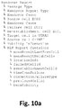
- FIG. 6 shows an embodiment of an RLF Report that is comprised of an RLFReportContainer element that includes the measResultLastServCell, failedPCellId, and the beamMobility information elements.
- the C-RNTI information element is not used if the UE used the RRC connection setup procedure rather than the RRC connection re-establishment procedure.
- the ShortMAC-I information element is provided to the source eNB to resolve a potential PCI confusion situation. Both, the C-RNTI and the ShortMAC-I are contained in the RRC Reestablishment Request message. The ShortMAC-I information element is not used if the UE used the RRC connection setup procedure rather than the RRC connection reestablishment procedure.
- the RLFReportContainer comprises RLF information, as it is described above with regard to the embodiment of FIGS. 5 b and 6 .
- beam specific information here the information elements bestBeamId, bestBeamMeasResult, detectedBeamsIds, detectedBeamsMeasResults are not included in a beamMobility container element, but instead are directly included as information elements of the RLFReportContainer.
- An apparatus comprising circuitry configured to receive or transmit a report, the report comprising beam specific information.
Abstract
Description
-
- information elements (bestBeamId, bestBeamMeasResult) that provide information about the Best beam ID and its measurements;
- an information element (beamMobility) that define the N number of best beam IDs and their measurements
- information elements (detectedBeamsIds, detectedBeamsMeasResults) that provide information about the beams detected by the User Equipment, e.g. the respective beam IDs and their measurements;
- information elements that identify beams above a predefined threshold and their ID and respective measurements;
- information elements (fallbackBeamID, fallbackBeamMeasResults) that provide fallback beam IDs where the User Equipment can fallback in the event of a failure of a main (serving) beam and corresponding measurements;
- an information element (servingBeamId) that provides the identity of the serving beam; information elements (neighbouringBeamsIds) that provide the identities of neighbouring beams;
- information elements (ULreferenceSignals) that provide User Equipment reference signals corresponding to a serving or neighbouring beam;
- an information element (SFNaeraId) that provides a Single Frequency Network Area ID;
- information elements (FailedBeamId, FailedBeamTimestamp) that provide a Failed beam ID and timestamp of a radio link failure;
- an information element (spentTime) that provides a time the User Equipment spent in a serving beam before the radio link failure happened;
- an information element that provides a time spent in a combination of a serving beam and its configured fallback beam; and
- an information element that provides a time spent in a fallback beam set.
-
- information elements (bestBeamId, bestBeamMeasResult) that provide information about the Best beam ID and its measurements;
- an information element (beamMobility) that define the N number of best beam IDs and their measurements
- information elements (detectedBeamsIds, detectedBeamsMeasResults) that provide information about the beams detected by the User Equipment, e.g. the respective beam IDs and their measurements;
- information elements that identify beams above a predefined threshold and their ID and respective measurements;
- information elements (fallbackBeamID, fallbackBeamMeasResults) that provide fallback beam IDs where the User Equipment can fallback in the event of a failure of a main (serving) beam and corresponding measurements;
- an information element (servingBeamId) that provides the identity of the serving beam; information elements (neighbouringBeamsIds) that provide the identities of neighbouring beams;
- information elements (ULreferenceSignals) that provide User Equipment reference signals corresponding to a serving or neighbouring beam;
- an information element (SFNaeraId) that provides a Single Frequency Network Area ID; information elements (FailedBeamId, FailedBeamTimestamp) that provide a Failed beam ID and timestamp of a radio link failure;
- an information element (spentTime) that provides a time the User Equipment spent in a serving beam before the radio link failure happened;
- an information element that provides a time spent in a combination of a serving beam and its configured fallback beam; and an information element that provides a time spent in a fallback beam set.
Claims (20)
Applications Claiming Priority (4)
| Application Number | Priority Date | Filing Date | Title |
|---|---|---|---|
| EP16206101 | 2016-12-22 | ||
| EP16206101 | 2016-12-22 | ||
| EP16206101.4 | 2016-12-22 | ||
| PCT/EP2017/084280 WO2018115387A1 (en) | 2016-12-22 | 2017-12-21 | Apparatus and method for a mobile telecommunications system |
Publications (2)
| Publication Number | Publication Date |
|---|---|
| US20190313273A1 US20190313273A1 (en) | 2019-10-10 |
| US11070998B2 true US11070998B2 (en) | 2021-07-20 |
Family
ID=57681373
Family Applications (1)
| Application Number | Title | Priority Date | Filing Date |
|---|---|---|---|
| US16/469,652 Active 2037-12-26 US11070998B2 (en) | 2016-12-22 | 2017-12-21 | Apparatus and method for a mobile telecommunications system |
Country Status (3)
| Country | Link |
|---|---|
| US (1) | US11070998B2 (en) |
| EP (1) | EP3560110A1 (en) |
| WO (1) | WO2018115387A1 (en) |
Families Citing this family (14)
| Publication number | Priority date | Publication date | Assignee | Title |
|---|---|---|---|---|
| TWI720052B (en) * | 2015-11-10 | 2021-03-01 | 美商Idac控股公司 | Wireless transmit/receive unit and wireless communication method |
| CN110326243B (en) * | 2017-01-05 | 2022-04-12 | Lg电子株式会社 | Method for transmitting and receiving uplink channel in wireless communication system and apparatus therefor |
| CN109150484B (en) | 2017-05-04 | 2020-01-21 | 华为技术有限公司 | Control information transmission method, related device and computer storage medium |
| KR102298575B1 (en) * | 2017-05-17 | 2021-09-06 | 엘지전자 주식회사 | Method for receiving downlink channel in wireless communication system and apparatus therefor |
| CN110876209B (en) * | 2018-08-31 | 2022-11-18 | 财团法人工业技术研究院 | Connection redirection method and user equipment |
| CN114900839A (en) * | 2018-09-28 | 2022-08-12 | 华为技术有限公司 | Method and device for transmitting information |
| CN114125966B (en) * | 2019-01-25 | 2024-01-05 | 中兴通讯股份有限公司 | Method and device for reporting failure of primary cell group |
| WO2020155094A1 (en) | 2019-02-01 | 2020-08-06 | Qualcomm Incorporated | Techniques for communicating mobility information |
| WO2020165244A1 (en) * | 2019-02-13 | 2020-08-20 | Sony Corporation | Network entity, user equipment, and method |
| US20220104300A1 (en) * | 2019-02-14 | 2022-03-31 | Telefonaktiebolaget Lm Ericsson (Publ) | Reporting From User Equipment to the Network for Radio Link Monitoring, Beam Failure Detection, and Beam Failure Recovery |
| CN112788693A (en) | 2019-11-08 | 2021-05-11 | 北京三星通信技术研究有限公司 | Method and device for supporting self-optimization |
| WO2021197413A1 (en) * | 2020-04-03 | 2021-10-07 | Shanghai Langbo Communication Technology Company Limited | Method and device in communication node for wireless communication |
| CN113709826A (en) * | 2020-05-21 | 2021-11-26 | 华为技术有限公司 | Communication method, device and system |
| CN113949421B (en) * | 2020-07-17 | 2023-02-24 | 维沃移动通信有限公司 | Method and device for determining beam information and electronic equipment |
Citations (5)
| Publication number | Priority date | Publication date | Assignee | Title |
|---|---|---|---|---|
| US20140036656A1 (en) * | 2012-08-03 | 2014-02-06 | Joey Chou | Coverage adjustment in e-utra networks |
| US20150092746A1 (en) | 2013-09-30 | 2015-04-02 | Telefonaktiebolaget L M Ericsson (Publ) | Enhancement on radio link failure report to record necessary timing details for a dual-threshold handover trigger event |
| US20160150435A1 (en) | 2014-11-26 | 2016-05-26 | Samsung Electronics Co., Ltd. | Communication method and apparatus using beamforming |
| US20190081688A1 (en) * | 2016-03-03 | 2019-03-14 | Idac Holdings, Inc. | Methods and apparatus for beam control in beamformed systems |
| US20190174346A1 (en) * | 2016-08-11 | 2019-06-06 | Convida Wireless, Llc | Beam management |
-
2017
- 2017-12-21 EP EP17822308.7A patent/EP3560110A1/en active Pending
- 2017-12-21 WO PCT/EP2017/084280 patent/WO2018115387A1/en unknown
- 2017-12-21 US US16/469,652 patent/US11070998B2/en active Active
Patent Citations (5)
| Publication number | Priority date | Publication date | Assignee | Title |
|---|---|---|---|---|
| US20140036656A1 (en) * | 2012-08-03 | 2014-02-06 | Joey Chou | Coverage adjustment in e-utra networks |
| US20150092746A1 (en) | 2013-09-30 | 2015-04-02 | Telefonaktiebolaget L M Ericsson (Publ) | Enhancement on radio link failure report to record necessary timing details for a dual-threshold handover trigger event |
| US20160150435A1 (en) | 2014-11-26 | 2016-05-26 | Samsung Electronics Co., Ltd. | Communication method and apparatus using beamforming |
| US20190081688A1 (en) * | 2016-03-03 | 2019-03-14 | Idac Holdings, Inc. | Methods and apparatus for beam control in beamformed systems |
| US20190174346A1 (en) * | 2016-08-11 | 2019-06-06 | Convida Wireless, Llc | Beam management |
Non-Patent Citations (5)
Also Published As
| Publication number | Publication date |
|---|---|
| EP3560110A1 (en) | 2019-10-30 |
| US20190313273A1 (en) | 2019-10-10 |
| WO2018115387A1 (en) | 2018-06-28 |
Similar Documents
| Publication | Publication Date | Title |
|---|---|---|
| US11070998B2 (en) | Apparatus and method for a mobile telecommunications system | |
| JP6908280B2 (en) | Wireless terminals, wireless communication systems, wireless stations, and methods thereof | |
| US10805168B2 (en) | Method and apparatus for performing cell specific procedure or mobility procedure for network slice-based NR in wireless communication system | |
| EP3488660B1 (en) | Methods and apparatuses for measurement report and computer-readable medium | |
| KR102083322B1 (en) | Apparatus and method for providing service to isolated user equipment in device-to-device communication system | |
| US11627512B2 (en) | Method and apparatus for transmitting data | |
| KR101889386B1 (en) | Autonomous connection switching in a wireless communication network | |
| US11310852B2 (en) | Apparatus and method related to dual connectivity | |
| US11924695B2 (en) | Mobile telecommunications system method including switching between radio resources based on measured signal properties | |
| US10064115B2 (en) | Method and apparatus for handover in dual connectivity user equipment and base station | |
| US20220061042A1 (en) | Enhancing handover performance using radio resource control diversity | |
| JPWO2015156324A1 (en) | Measurement control method and base station | |
| US9930581B2 (en) | Addressing communication failure in multiple connection systems | |
| EP3125639B1 (en) | Communication control method, device and system for mobile terminal | |
| US11012880B2 (en) | Wireless communication devices, network connection nodes, systems and methods | |
| US9402195B2 (en) | Operation of base station in a cellular communications network | |
| EP3097741A1 (en) | Methods and network nodes for radio link failure, rlf, reporting using a rlf indicaton procedure in an evolved node b, enb | |
| US20210289427A1 (en) | Entity and user equipment for a mobile telecommunications system | |
| CN104904294A (en) | Terminal device, base station device, communications system, and communications method | |
| WO2016126174A1 (en) | A first radio access node, a second radio access node, a first core network node and methods therein for preparing handover | |
| CN112312492B (en) | Switching method, system and terminal equipment for switching |
Legal Events
| Date | Code | Title | Description |
|---|---|---|---|
| FEPP | Fee payment procedure |
Free format text: ENTITY STATUS SET TO UNDISCOUNTED (ORIGINAL EVENT CODE: BIG.); ENTITY STATUS OF PATENT OWNER: LARGE ENTITY |
|
| AS | Assignment |
Owner name: SONY CORPORATION, JAPAN Free format text: ASSIGNMENT OF ASSIGNORS INTEREST;ASSIGNOR:MARTIN, BRIAN ALEXANDER;REEL/FRAME:050343/0987 Effective date: 20190711 Owner name: SONY EUROPE LIMITED, UNITED KINGDOM Free format text: ASSIGNMENT OF ASSIGNORS INTEREST;ASSIGNOR:SARASWATI BP LTD.;REEL/FRAME:050348/0525 Effective date: 20190403 Owner name: SONY CORPORATION, JAPAN Free format text: ASSIGNMENT OF ASSIGNORS INTEREST;ASSIGNOR:SONY EUROPE LIMITED;REEL/FRAME:050343/0861 Effective date: 20190312 Owner name: SARASWATI BP LTD., UNITED KINGDOM Free format text: ASSIGNMENT OF ASSIGNORS INTEREST;ASSIGNOR:SHARMA, VIVEK;REEL/FRAME:050348/0449 Effective date: 20190403 Owner name: SONY EUROPE LIMITED, UNITED KINGDOM Free format text: ASSIGNMENT OF ASSIGNORS INTEREST;ASSIGNORS:WAKABAYASHI, HIDEJI;TSUDA, SHINICHIRO;WEI, YUXIN;SIGNING DATES FROM 20190228 TO 20190315;REEL/FRAME:050351/0618 |
|
| AS | Assignment |
Owner name: SARASWATI BP LTD., UNITED KINGDOM Free format text: CORRECTIVE ASSIGNMENT TO CORRECT THE EXECUTION DATE PREVIOUSLY RECORDED AT REEL: 50348 FRAME: 449. ASSIGNOR(S) HEREBY CONFIRMS THE ASSIGNMENT;ASSIGNOR:SHARMA, VIVEK;REEL/FRAME:051833/0053 Effective date: 20190304 Owner name: SONY EUROPE LIMITED, UNITED KINGDOM Free format text: CORRECTIVE ASSIGNMENT TO CORRECT THE SIGNATURE DATE ON ASSIGNMENT COVER PAGE. NEEDS TO BE CORRECTED FROM APRIL 3, 2019 TO MARCH 4, 2019 PREVIOUSLY RECORDED ON REEL 050348 FRAME 0525. ASSIGNOR(S) HEREBY CONFIRMS THE ASSIGNMENT;ASSIGNOR:SARASWATI BP LTD.;REEL/FRAME:051833/0084 Effective date: 20190304 |
|
| AS | Assignment |
Owner name: SONY CORPORATION, JAPAN Free format text: ASSIGNMENT OF ASSIGNORS INTEREST;ASSIGNOR:SONY EUROPE LIMITED;REEL/FRAME:052045/0696 Effective date: 20190319 |
|
| STPP | Information on status: patent application and granting procedure in general |
Free format text: NON FINAL ACTION MAILED |
|
| STPP | Information on status: patent application and granting procedure in general |
Free format text: RESPONSE TO NON-FINAL OFFICE ACTION ENTERED AND FORWARDED TO EXAMINER |
|
| STPP | Information on status: patent application and granting procedure in general |
Free format text: FINAL REJECTION MAILED |
|
| STPP | Information on status: patent application and granting procedure in general |
Free format text: RESPONSE AFTER FINAL ACTION FORWARDED TO EXAMINER |
|
| STPP | Information on status: patent application and granting procedure in general |
Free format text: NOTICE OF ALLOWANCE MAILED -- APPLICATION RECEIVED IN OFFICE OF PUBLICATIONS |
|
| STPP | Information on status: patent application and granting procedure in general |
Free format text: PUBLICATIONS -- ISSUE FEE PAYMENT RECEIVED |
|
| STPP | Information on status: patent application and granting procedure in general |
Free format text: PUBLICATIONS -- ISSUE FEE PAYMENT VERIFIED |
|
| STCF | Information on status: patent grant |
Free format text: PATENTED CASE |