US11070801B2 - Image coder/decoder restricting binary tree splitting of target node obtained by ternary tree split - Google Patents
Image coder/decoder restricting binary tree splitting of target node obtained by ternary tree split Download PDFInfo
- Publication number
- US11070801B2 US11070801B2 US16/469,673 US201716469673A US11070801B2 US 11070801 B2 US11070801 B2 US 11070801B2 US 201716469673 A US201716469673 A US 201716469673A US 11070801 B2 US11070801 B2 US 11070801B2
- Authority
- US
- United States
- Prior art keywords
- split
- flag
- block
- case
- information decoder
- Prior art date
- Legal status (The legal status is an assumption and is not a legal conclusion. Google has not performed a legal analysis and makes no representation as to the accuracy of the status listed.)
- Active
Links
- 238000000034 method Methods 0.000 claims abstract description 45
- 238000005192 partition Methods 0.000 claims description 18
- 238000012545 processing Methods 0.000 description 312
- 238000010586 diagram Methods 0.000 description 138
- 238000013139 quantization Methods 0.000 description 39
- 230000005540 biological transmission Effects 0.000 description 24
- 238000004891 communication Methods 0.000 description 15
- 230000006854 communication Effects 0.000 description 15
- 230000008929 regeneration Effects 0.000 description 13
- 238000011069 regeneration method Methods 0.000 description 13
- 230000006870 function Effects 0.000 description 12
- 239000010410 layer Substances 0.000 description 11
- 238000009795 derivation Methods 0.000 description 8
- 229920000069 polyphenylene sulfide Polymers 0.000 description 6
- 230000008569 process Effects 0.000 description 5
- 208000034188 Stiff person spectrum disease Diseases 0.000 description 4
- 229920010524 Syndiotactic polystyrene Polymers 0.000 description 4
- 230000003044 adaptive effect Effects 0.000 description 4
- 208000012112 ischiocoxopodopatellar syndrome Diseases 0.000 description 4
- 238000012805 post-processing Methods 0.000 description 4
- 238000002490 spark plasma sintering Methods 0.000 description 4
- 238000005516 engineering process Methods 0.000 description 3
- 230000010354 integration Effects 0.000 description 3
- VBRBNWWNRIMAII-WYMLVPIESA-N 3-[(e)-5-(4-ethylphenoxy)-3-methylpent-3-enyl]-2,2-dimethyloxirane Chemical compound C1=CC(CC)=CC=C1OC\C=C(/C)CCC1C(C)(C)O1 VBRBNWWNRIMAII-WYMLVPIESA-N 0.000 description 2
- 101100162210 Aspergillus parasiticus (strain ATCC 56775 / NRRL 5862 / SRRC 143 / SU-1) aflM gene Proteins 0.000 description 2
- 101100102500 Caenorhabditis elegans ver-1 gene Proteins 0.000 description 2
- 230000000694 effects Effects 0.000 description 2
- 238000005401 electroluminescence Methods 0.000 description 2
- 238000003384 imaging method Methods 0.000 description 2
- 230000003287 optical effect Effects 0.000 description 2
- NRNCYVBFPDDJNE-UHFFFAOYSA-N pemoline Chemical compound O1C(N)=NC(=O)C1C1=CC=CC=C1 NRNCYVBFPDDJNE-UHFFFAOYSA-N 0.000 description 2
- 230000009467 reduction Effects 0.000 description 2
- 239000004065 semiconductor Substances 0.000 description 2
- 230000011664 signaling Effects 0.000 description 2
- 241001025261 Neoraja caerulea Species 0.000 description 1
- 230000008901 benefit Effects 0.000 description 1
- 230000007175 bidirectional communication Effects 0.000 description 1
- 230000002457 bidirectional effect Effects 0.000 description 1
- 230000001413 cellular effect Effects 0.000 description 1
- 238000012937 correction Methods 0.000 description 1
- 230000001419 dependent effect Effects 0.000 description 1
- 238000013461 design Methods 0.000 description 1
- 230000006872 improvement Effects 0.000 description 1
- 239000011229 interlayer Substances 0.000 description 1
- 239000004973 liquid crystal related substance Substances 0.000 description 1
- OSWPMRLSEDHDFF-UHFFFAOYSA-N methyl salicylate Chemical compound COC(=O)C1=CC=CC=C1O OSWPMRLSEDHDFF-UHFFFAOYSA-N 0.000 description 1
- 238000010295 mobile communication Methods 0.000 description 1
- 238000012986 modification Methods 0.000 description 1
- 230000004048 modification Effects 0.000 description 1
- 230000002093 peripheral effect Effects 0.000 description 1
- 239000002356 single layer Substances 0.000 description 1
- 239000007787 solid Substances 0.000 description 1
- 230000000153 supplemental effect Effects 0.000 description 1
- 238000012360 testing method Methods 0.000 description 1
- 230000007704 transition Effects 0.000 description 1
Images


Classifications
-
- H—ELECTRICITY
- H04—ELECTRIC COMMUNICATION TECHNIQUE
- H04N—PICTORIAL COMMUNICATION, e.g. TELEVISION
- H04N19/00—Methods or arrangements for coding, decoding, compressing or decompressing digital video signals
- H04N19/10—Methods or arrangements for coding, decoding, compressing or decompressing digital video signals using adaptive coding
- H04N19/102—Methods or arrangements for coding, decoding, compressing or decompressing digital video signals using adaptive coding characterised by the element, parameter or selection affected or controlled by the adaptive coding
- H04N19/119—Adaptive subdivision aspects, e.g. subdivision of a picture into rectangular or non-rectangular coding blocks
-
- H—ELECTRICITY
- H04—ELECTRIC COMMUNICATION TECHNIQUE
- H04N—PICTORIAL COMMUNICATION, e.g. TELEVISION
- H04N19/00—Methods or arrangements for coding, decoding, compressing or decompressing digital video signals
- H04N19/10—Methods or arrangements for coding, decoding, compressing or decompressing digital video signals using adaptive coding
- H04N19/134—Methods or arrangements for coding, decoding, compressing or decompressing digital video signals using adaptive coding characterised by the element, parameter or criterion affecting or controlling the adaptive coding
- H04N19/157—Assigned coding mode, i.e. the coding mode being predefined or preselected to be further used for selection of another element or parameter
-
- H—ELECTRICITY
- H04—ELECTRIC COMMUNICATION TECHNIQUE
- H04N—PICTORIAL COMMUNICATION, e.g. TELEVISION
- H04N19/00—Methods or arrangements for coding, decoding, compressing or decompressing digital video signals
- H04N19/10—Methods or arrangements for coding, decoding, compressing or decompressing digital video signals using adaptive coding
- H04N19/169—Methods or arrangements for coding, decoding, compressing or decompressing digital video signals using adaptive coding characterised by the coding unit, i.e. the structural portion or semantic portion of the video signal being the object or the subject of the adaptive coding
- H04N19/17—Methods or arrangements for coding, decoding, compressing or decompressing digital video signals using adaptive coding characterised by the coding unit, i.e. the structural portion or semantic portion of the video signal being the object or the subject of the adaptive coding the unit being an image region, e.g. an object
- H04N19/176—Methods or arrangements for coding, decoding, compressing or decompressing digital video signals using adaptive coding characterised by the coding unit, i.e. the structural portion or semantic portion of the video signal being the object or the subject of the adaptive coding the unit being an image region, e.g. an object the region being a block, e.g. a macroblock
-
- H—ELECTRICITY
- H04—ELECTRIC COMMUNICATION TECHNIQUE
- H04N—PICTORIAL COMMUNICATION, e.g. TELEVISION
- H04N19/00—Methods or arrangements for coding, decoding, compressing or decompressing digital video signals
- H04N19/70—Methods or arrangements for coding, decoding, compressing or decompressing digital video signals characterised by syntax aspects related to video coding, e.g. related to compression standards
-
- H—ELECTRICITY
- H04—ELECTRIC COMMUNICATION TECHNIQUE
- H04N—PICTORIAL COMMUNICATION, e.g. TELEVISION
- H04N19/00—Methods or arrangements for coding, decoding, compressing or decompressing digital video signals
- H04N19/90—Methods or arrangements for coding, decoding, compressing or decompressing digital video signals using coding techniques not provided for in groups H04N19/10-H04N19/85, e.g. fractals
- H04N19/96—Tree coding, e.g. quad-tree coding
Definitions
- the embodiments of the present invention relate to a prediction image generation apparatus, a video decoding apparatus, and a video coding apparatus.
- a video coding apparatus which generates coded data by coding a video, and a video decoding apparatus which generates decoded images by decoding the coded data are used to transmit or record a video efficiently.
- video coding schemes include methods suggested in H.264/AVC and High-Efficiency Video Coding (HEVC).
- HEVC High-Efficiency Video Coding
- images (pictures) constituting a video are managed by a hierarchy structure including slices obtained by splitting images, coding units (also sometimes referred to as Coding Units (CUs)) obtained by splitting slices, Prediction Units (PUs) which are blocks obtained by splitting coding units, and Transform Units (TUs), and are coded/decoded for each CU.
- coding units also sometimes referred to as Coding Units (CUs)
- PUs Prediction Units
- TUs Transform Units
- a prediction image is generated based on local decoded images obtained by coding/decoding input images, and prediction residual (also sometimes referred to as “difference images” or “residual images”) obtained by subtracting the prediction images from input images (original image) are coded.
- prediction residual also sometimes referred to as “difference images” or “residual images” obtained by subtracting the prediction images from input images (original image) are coded.
- Generation methods of prediction images include an inter-screen prediction (an inter prediction) and an intra-screen prediction (intra prediction).
- NPL 1 and NPL 2 Examples of a technique of recent video coding and decoding are described in NPL 1 and NPL 2.
- NPL 2 introduces Binary Tree (BT) split and Ternary Tree (TT) split, in addition to Quad Tree (QT) split. Accordingly, there are more split patterns of a CU, which makes coding/decoding more complex. Implementation of complex split patterns has still been uneasy, and therefore there has been a demand for further improvement in terms of enhancement in coding efficiency.
- BT Binary Tree
- TT Ternary Tree
- QT Quad Tree
- the present invention is achieved in view of the problem described above, and has an object to provide an image decoding apparatus and an image coding apparatus that are capable of reducing complexity of coding/decoding of a video.
- the present invention has another object to provide an image decoding apparatus and an image coding apparatus that are capable of implementing complex split patterns with less split depth.
- an image decoding apparatus for decoding a picture for each of coding tree units, the image decoding apparatus including a split unit configured to hierarchically split a coding node of the coding tree units by at least any of binary tree split and ternary tree split, wherein the split unit refers to a method of splitting an immediately higher node, which is a node one generation higher than a target node, to restrict a method of splitting the target node.
- An image decoding apparatus is an image decoding apparatus for decoding a picture for each of coding tree units, the image decoding apparatus including a split unit configured to hierarchically split a coding node of the coding tree units, wherein in a case that a target node has a rectangular shape with an aspect ratio of a prescribed value or greater, the split unit restricts split of the target node by ternary tree split that generates boundaries along a longitudinal direction of the target node.
- An image decoding apparatus is an image decoding apparatus for decoding a picture for each of coding tree units, the image decoding apparatus including a split unit configured to hierarchically split a coding node of the coding tree units by at least any of binary tree split and ternary tree split, wherein the split unit refers to a depth variable common to binary tree split and ternary tree split to restrict split of a target node.
- An image coding apparatus is an image coding apparatus for splitting a picture into coding tree units to code the picture, the image coding apparatus including a split unit configured to hierarchically split a coding node of the coding tree units by at least any of binary tree split and ternary tree split, wherein the split unit refers to a method of splitting an immediately higher node, which is a node one generation higher than a target node, to restrict a method of splitting the target node.
- An image coding apparatus is an image coding apparatus for splitting a picture into coding tree units to code the picture, the image coding apparatus including a split unit configured to hierarchically split a coding node of the coding tree units, wherein in a case that a target node has a rectangular shape with an aspect ratio of a prescribed value or greater, the split unit restricts split of the target node by ternary tree split that generates boundaries along a longitudinal direction of the target node.
- An image coding apparatus is an image coding apparatus for splitting a picture into coding tree units to code the picture, the image coding apparatus including a split unit configured to hierarchically split a coding node of the coding tree units by at least any of binary tree split and ternary tree split, wherein the split unit refers to a depth variable common to binary tree split and ternary tree split to restrict split of a target node.
- An image coding apparatus is an image decoding apparatus for decoding a picture for each of coding tree units, the image decoding apparatus including a split unit configured to split a coding node of the coding tree units, wherein the split unit refers to a first flag, a second flag, and a third flag, and in a case that the first flag indicates that split is to be performed by a first split type group, the first split type group including a split type for splitting a target node into nodes in 1:1:1:1 in a first direction to split the target node into four nodes, and quad tree split, and that the second flag indicates that split is to be performed by a split type for splitting into the four nodes, the split unit employs a direction indicated by the third flag as the first direction to split the target node into the four nodes.
- complexity of coding/decoding of a video can be reduced.
- An image decoding apparatus and an image coding apparatus that are capable of implementing complex split patterns with less split depth can be provided.
- FIG. 1 is a diagram illustrating a hierarchy structure of data of a coding stream according to the present embodiment.
- FIGS. 2A to 2H are diagrams illustrating patterns of PU split modes.
- FIGS. 2A to 2H illustrate partition shapes in cases that PU split modes are 2N ⁇ 2N, 2N ⁇ N, 2N ⁇ nU, 2N ⁇ nD, N ⁇ 2N, nL ⁇ 2N, nR ⁇ 2N, and N ⁇ N, respectively.
- FIGS. 3A and 3B are conceptual diagrams illustrating an example of reference pictures and reference picture lists.
- FIG. 4 is block diagram illustrating a configuration of an image coding apparatus according to the present embodiment.
- FIG. 5 is a schematic diagram illustrating a configuration of an image decoding apparatus according to the present embodiment.
- FIG. 6 is a schematic diagram illustrating a configuration of an inter prediction image generation unit of the image coding apparatus according to the present embodiment.
- FIGS. 7A to 7F are diagrams illustrating splits of a coding node in the image decoding apparatus according to the present embodiment.
- FIG. 8 is a diagram illustrating signaling of tree types performed by the image decoding apparatus according to the present embodiment.
- FIG. 9 is a diagram illustrating an example in which the same split pattern is obtained through split processes of a block.
- FIG. 10 is a block diagram illustrating a configuration of the image decoding apparatus according to the present embodiment.
- FIG. 11 is a flowchart illustrating decoding processing according to the present embodiment.
- FIG. 12 is a diagram illustrating a configuration example of a syntax table of QT information according to the present embodiment.
- FIGS. 13A to 13F are diagrams illustrating examples of split patterns of the image decoding apparatus according to the present embodiment.
- FIGS. 14A to 14H are diagrams illustrating examples of split patterns of the image decoding apparatus according to the present embodiment.
- FIGS. 15A to 15D are diagrams illustrating examples of split patterns of the image decoding apparatus according to the present embodiment.
- FIG. 16 is a flowchart illustrating decoding processing according to the present embodiment.
- FIGS. 17A and 17B are configuration diagrams of pseudocodes according to the present embodiment.
- FIGS. 18A and 18B are configuration diagrams of pseudocodes according to the present embodiment.
- FIGS. 19A and 19B are configuration diagrams of pseudocodes according to the present embodiment.
- FIG. 20 is a configuration diagram of a pseudocode according to the present embodiment.
- FIG. 21 is a configuration diagram of a pseudocode according to the present embodiment.
- FIG. 22 is a configuration diagram of a pseudocode according to the present embodiment.
- FIG. 23 is a configuration diagram of a pseudocode according to the present embodiment.
- FIG. 24 is a configuration diagram of a pseudocode according to the present embodiment.
- FIG. 25 is a configuration diagram of a pseudocode according to the present embodiment.
- FIG. 26 is a configuration diagram of a pseudocode according to the present embodiment.
- FIGS. 27A to 27C are configuration diagrams of pseudocodes according to the present embodiment.
- FIG. 28 is a configuration diagram of a pseudocode according to the present embodiment.
- FIG. 29 is a configuration diagram of a pseudocode according to the present embodiment.
- FIG. 30 is a configuration diagram of a pseudocode according to the present embodiment.
- FIG. 31 is a configuration diagram of a pseudocode according to the present embodiment.
- FIG. 32 is a configuration diagram of a pseudocode according to the present embodiment.
- FIGS. 33A and 33B are configuration diagrams of pseudocodes according to the present embodiment.
- FIGS. 34A to 34D are configuration diagrams of pseudocodes according to the present embodiment.
- FIGS. 35A and 35B are configuration diagrams of pseudocodes according to the present embodiment.
- FIGS. 36A to 36D are configuration diagrams of pseudocodes according to the present embodiment.
- FIGS. 37A and 37B are configuration diagrams of pseudocodes according to the present embodiment.
- FIGS. 38A and 38B are configuration diagrams of pseudocodes according to the present embodiment.
- FIGS. 39A and 39B are configuration diagrams of pseudocodes according to the present embodiment.
- FIG. 40 is a diagram illustrating split patterns of a block.
- FIGS. 41A to 41C are diagrams illustrating examples of split patterns of the image decoding apparatus according to the present embodiment.
- FIG. 42 is a configuration diagram of a pseudocode according to the present embodiment.
- FIG. 43 is a configuration diagram of a pseudocode according to the present embodiment.
- FIG. 44 is a configuration diagram of a pseudocode according to the present embodiment.
- FIGS. 45A and 45B are configuration diagrams of pseudocodes according to the present embodiment.
- FIG. 45C is a diagram illustrating block splits according to the present embodiment.
- FIG. 46A is a configuration diagram of a pseudocode according to the present embodiment.
- FIG. 46B is a diagram illustrating block splits according to the present embodiment.
- FIGS. 47A to 47L are diagrams illustrating examples of split patterns of the image decoding apparatus according to the present embodiment.
- FIG. 48 is a configuration diagram of a pseudocode according to the present embodiment.
- FIGS. 49A and 49B are diagrams illustrating examples of split patterns of the image decoding apparatus according to the present embodiment.
- FIG. 50 is a flowchart illustrating decoding processing according to the present embodiment.
- FIG. 51 is a configuration diagram of a pseudocode according to the present embodiment.
- FIG. 52 is a configuration diagram of a pseudocode according to the present embodiment.
- FIGS. 53A to 53G are diagrams illustrating other examples of splits of a coding node in the image decoding apparatus according to the present embodiment.
- FIGS. 54A to 54D are diagrams illustrating yet other examples of splits of a coding node in the image decoding apparatus according to the present embodiment.
- FIG. 55 is a flowchart illustrating decoding processing according to the present embodiment.
- FIGS. 56A and 56B are configuration diagrams of pseudocodes according to the present embodiment.
- FIG. 57 is a flowchart illustrating decoding processing according to the present embodiment.
- FIGS. 58A to 58C are configuration diagrams of pseudocodes according to the present embodiment.
- FIG. 59 is a diagram illustrating examples of flags and shapes of a coding node according to the present embodiment.
- FIGS. 60A to 60C are configuration diagrams of pseudocodes according to the present embodiment.
- FIG. 61 is a table illustrating examples of flags and shapes of a coding node according to the present embodiment.
- FIGS. 62A to 62C are configuration diagrams of pseudocodes according to the present embodiment.
- FIG. 63 is a diagram illustrating examples of flags and shapes of a coding node according to the present embodiment.
- FIG. 64 is a flowchart illustrating decoding processing according to the present embodiment.
- FIGS. 65A to 65C are configuration diagrams of pseudocodes according to the present embodiment.
- FIG. 66 is a diagram illustrating examples of flags and shapes of a coding node according to the present embodiment.
- FIG. 67 is a flowchart illustrating decoding processing according to the present embodiment.
- FIGS. 68A to 68C are configuration diagrams of pseudocodes according to the present embodiment.
- FIG. 69 is a diagram illustrating examples of flags and shapes of a coding node according to the present embodiment.
- FIGS. 70A to 70C are configuration diagrams of pseudocodes according to the present embodiment.
- FIG. 71 is a diagram illustrating examples of flags and shapes of a coding node according to the present embodiment.
- FIG. 72 is a flowchart illustrating decoding processing according to the present embodiment.
- FIGS. 73A to 73C are configuration diagrams of pseudocodes according to the present embodiment.
- FIG. 74 is a diagram illustrating examples of flags and shapes of a coding node according to the present embodiment.
- FIGS. 75A and 75B are diagrams illustrating configurations of a transmitting apparatus equipped with the image coding apparatus and a receiving apparatus equipped with the image decoding apparatus according to the present embodiment.
- FIG. 75A illustrates the transmitting apparatus equipped with the image coding apparatus
- FIG. 75B illustrates the receiving apparatus equipped with the image decoding apparatus.
- FIGS. 76A and 76B are diagrams illustrating configurations of a recording apparatus equipped with the image coding apparatus and a regeneration apparatus equipped with the image decoding apparatus according to the present embodiment.
- FIG. 76A illustrates the recording apparatus equipped with the image coding apparatus
- FIG. 76B illustrates the regeneration apparatus equipped with the image decoding apparatus.
- FIG. 77 is a schematic diagram illustrating a configuration of an image transmission system according to the present embodiment.
- FIG. 77 is a schematic diagram illustrating a configuration of an image transmission system 1 according to the present embodiment.
- the image transmission system 1 is a system configured to transmit codes of a coding target image having been coded, decode the transmitted codes, and display an image.
- the image transmission system 1 includes an image coding apparatus (video coding apparatus) 11 , a network 21 , an image decoding apparatus (video decoding apparatus) 31 , and an image display apparatus 41 .
- An image T indicating an image of a single layer or multiple layers is input to the image coding apparatus 11 .
- a layer is a concept used to distinguish multiple pictures in a case that there are one or more pictures to configure a certain time. For example, coding an identical picture in multiple layers having different image qualities and resolutions is scalable coding, and coding pictures having different viewpoints in multiple layers is view scalable coding.
- a prediction an inter-layer prediction, an inter-view prediction
- coded data can be compiled.
- the network 21 transmits a coding stream Te generated by the image coding apparatus 11 to the image decoding apparatus 31 .
- the network 21 is the Internet (internet), Wide Area Network (WAN), Local Area Network (LAN), or combinations thereof.
- the network 21 is not necessarily a bidirectional communication network, but may be a unidirectional communication network configured to transmit broadcast wave such as digital terrestrial television broadcasting and satellite broadcasting.
- the network 21 may be substituted by a storage medium that records the coding stream Te, such as Digital Versatile Disc (DVD) and Blue-ray Disc (BD).
- DVD Digital Versatile Disc
- BD Blue-ray Disc
- the image decoding apparatus 31 decodes each of the coding streams Te transmitted by the network 21 , and generates one or multiple decoded images Td.
- the image display apparatus 41 displays all or part of one or multiple decoded images Td generated by the image decoding apparatus 31 .
- the image display apparatus 41 includes a display device such as a liquid crystal display and an organic Electro-luminescence (EL) display.
- EL Electro-luminescence
- spacial scalable coding and SNR scalable coding in a case that the image decoding apparatus 31 has high processing capability, an enhanced layer image having high image quality is displayed. In a case that the image decoding apparatus 31 only has lower processing capability, a base layer image which does not require as high processing capability and display capability as an enhanced layer is displayed.
- x? y z is a ternary operator to take y in a case that x is true (other than 0), and take z in a case that x is false (0).
- FIGS. 1A to IF are diagrams illustrating a hierarchy structure of data in the coding stream Te.
- the coding stream Te includes a sequence and multiple pictures constituting a sequence illustratively.
- FIGS. 1A to IF are diagrams illustrating a coding video sequence prescribing a sequence SEQ, a coding picture prescribing a picture PICT, a coding slice prescribing a slice S, a coding slice data prescribing slice data, a coding tree unit included in coding slice data, and Coding Units (CUs) included in a coding tree unit, respectively.
- CUs Coding Units
- the sequence SEQ includes a Video Parameter Set, a Sequence Parameter Set SPS, a Picture Parameter Set PPS, a picture PICT, and Supplemental Enhancement Information SEI.
- a value indicated after # indicates a layer ID.
- FIGS. 1A to IF although an example is illustrated where coded data of #0 and #1, in other words, layer 0 and layer 1 exist, types of layers and the number of layers do not depend on this.
- a set of coding parameters common to multiple videos and a set of coding parameters associated with multiple layers and an individual layer included in a video are prescribed.
- sequence parameter set SPS a set of coding parameters referred to by the image decoding apparatus 31 to decode a target sequence is prescribed. For example, width and height of a picture are prescribed. Note that multiple SPSs may exist. In that case, any of multiple SPSs is selected from the PPS.
- a set of coding parameters referred to by the image decoding apparatus 31 to decode each picture in a target sequence is prescribed.
- a reference value (pic_init_qp_minus26) of a quantization step size used for decoding of a picture and a flag (weighted_pred_flag) indicating an application of a weighted prediction are included.
- multiple PPSs may exist. In that case, any of multiple PPSs is selected from each picture in a target sequence.
- the picture PICT includes slices S 0 to S NS-1 (NS is the total number of slices included in the picture PICT).
- the slice S includes a slice header SH and a slice data SDATA.
- the slice header SH includes a coding parameter group referred to by the image decoding apparatus 31 to determine a decoding method of a target slice.
- Slice type specification information (slice_type) to specify a slice type is one example of a coding parameter included in the slice header SH.
- slice types that can be specified by the slice type specification information include (1) I slice using only an intra prediction in coding, (2) P slice using a unidirectional prediction or an intra prediction in coding, and (3) B slice using a unidirectional prediction, a bidirectional prediction, or an intra prediction in coding, and the like.
- the slice header SH may include a reference (pic_parameter_set_id) to the picture parameter set PPS included in the coding video sequence.
- the slice data SDATA includes Coding Tree Units (CTUs).
- the CTU is a block of a fixed size (for example, 64 ⁇ 64) constituting a slice, and may be referred to as a Largest Coding Unit (LCU).
- LCU Largest Coding Unit
- a set of data referred to by the image decoding apparatus 31 to decode a coding tree unit of a processing target is prescribed.
- the coding tree unit is split by recursive quad tree splits. Nodes of a tree structure obtained by recursive quad tree splits are referred to as Coding Nodes (CNs). Intermediate nodes of a quad tree are coding nodes, and the coding tree unit itself is also prescribed as the highest coding node.
- the CTU includes a split flag (cu_split_flag), and in a case that cu_split_flag is 1, the CTU is split into four coding node CNs.
- the coding node CN is not split, and has one Coding Unit (CU) as a node.
- the coding unit CU is an end node of the coding nodes, and is not split anymore.
- the coding unit CU is a basic unit of coding processing.
- the size of the coding tree unit CTU is 64 ⁇ 64 pixels
- the size of the coding unit may be any of 64 ⁇ 64 pixels, 32 ⁇ 32 pixels, 16 ⁇ 16 pixels, and 8 ⁇ 8 pixels.
- the coding unit includes a prediction tree, a transform tree, and a CU header CUH.
- a prediction mode In the CU header, a prediction mode, a split method (PU split mode), and the like are prescribed.
- prediction information (a reference picture index, a motion vector, and the like) of each prediction unit (PU) where the coding unit is split into one or multiple is prescribed.
- the prediction unit is one or multiple non-overlapping regions constituting the coding unit.
- the prediction tree includes one or multiple prediction units obtained by the above-mentioned split. Note that, in the following, a unit of prediction where the prediction unit is further split is referred to as a “subblock”.
- the subblock includes multiple pixels. In a case that the sizes of the prediction unit and the subblock are the same, there is one subblock in the prediction unit. In a case that the prediction unit is larger than the size of the subblock, the prediction unit is split into subblocks. For example, in a case that the prediction unit is 8 ⁇ 8, and the subblock is 4 ⁇ 4, the prediction unit is split into four subblocks formed by horizontal split into two and vertical split into two.
- the prediction processing may be performed for each of these prediction units (subblocks).
- the intra prediction is a prediction in an identical picture
- the inter prediction refers to a prediction processing performed between mutually different pictures (for example, between display times, and between layer images).
- the split method has 2N ⁇ 2N (the same size as the coding unit) and N ⁇ N.
- the split method includes coding by a PU split mode (part_mode) of the coded data, and includes 2N ⁇ 2N (the same size as the coding unit), 2N ⁇ N, 2N ⁇ nU, 2N ⁇ nD, N ⁇ 2N, nL ⁇ 2N, nR ⁇ 2N and N ⁇ N, and the like.
- 2N ⁇ N and N ⁇ 2N indicate a symmetric split of 1:1
- 2N ⁇ nU, 2N ⁇ nD and nL ⁇ 2N, nR ⁇ 2N indicate an asymmetry split of 1:3 and 3:1.
- the PUs included in the CU are expressed as PU 0 , PU 1 , PU 2 , and PU 3 sequentially.
- FIGS. 2A to 2H illustrate shapes of partitions in respective PU split modes (positions of boundaries of PU split) specifically.
- FIG. 2A illustrates a partition of 2N ⁇ 2N
- FIGS. 2B to 2D illustrate partitions (horizontally long partitions) of 2N ⁇ N, 2N ⁇ nU, and 2N ⁇ nD, respectively.
- FIGS. 2E to 2G illustrate partitions (vertically long partitions) in cases of N ⁇ 2N, nL ⁇ 2N, and nR ⁇ 2N, respectively
- FIG. 2H illustrates a partition of N ⁇ N. Note that horizontally long partitions and vertically long partitions are collectively referred to as rectangular partitions, and 2N ⁇ 2N and N ⁇ N are collectively referred to as square partitions.
- the coding unit is split into one or multiple transform units, and a position and a size of each transform unit are prescribed.
- the transform unit is one or multiple non-overlapping regions constituting the coding unit.
- the transform tree includes one or multiple transform units obtained by the above-mentioned split.
- Splits in the transform tree include those to allocate a region that is the same size as the coding unit as a transform unit, and those by recursive quad tree splits similar to the above-mentioned split of CUs.
- a transform processing is performed for each of these transform units.
- FIG. 5 is a schematic diagram illustrating a configuration of the image decoding apparatus 31 according to the present embodiment.
- the image decoding apparatus 31 includes an entropy decoder 301 , a prediction parameter decoder (a prediction image decoding apparatus) 302 , a loop filter 305 , a reference picture memory 306 , a prediction parameter memory 307 , a prediction image generation unit (prediction image generation apparatus) 308 , an inverse quantization and inverse DCT unit 311 , and an addition unit 312 .
- the prediction parameter decoder 302 includes an inter prediction parameter decoder 303 and an intra prediction parameter decoder 304 .
- the prediction image generation unit 308 includes an inter prediction image generation unit 309 and an intra prediction image generation unit 310 .
- the entropy decoder 301 performs entropy decoding on the coding stream Te input from the outside, and separates and decodes individual codes (syntax elements). Separated codes include prediction information to generate a prediction image and residual information to generate a difference image and the like.
- the entropy decoder 301 outputs a part of the separated codes to the prediction parameter decoder 302 .
- a part of the separated codes includes a prediction mode predMode, a PU split mode part_mode, a merge flag merge_flag, a merge index merge_idx, an inter prediction indicator inter_pred_idc, a reference picture index refldxLX, a prediction vector index mvp_LX_idx, and a difference vector mvdLX.
- the control of which code to decode is performed based on an indication of the prediction parameter decoder 302 .
- the entropy decoder 301 outputs quantization coefficients to the inverse quantization and inverse DCT unit 311 . These quantization coefficients are coefficients obtained by performing Discrete Cosine Transform (DCT) on residual signal to quantize in coding processing.
- DCT Discrete Cosine Transform
- the inter prediction parameter decoder 303 decodes an inter prediction parameter with reference to a prediction parameter stored in the prediction parameter memory 307 , based on a code input from the entropy decoder 301 .
- the inter prediction parameter decoder 303 outputs a decoded inter prediction parameter to the prediction image generation unit 308 , and also stores the decoded inter prediction parameter in the prediction parameter memory 307 . Details of the inter prediction parameter decoder 303 will be described later.
- the intra prediction parameter decoder 304 decodes an intra prediction parameter with reference to a prediction parameter stored in the prediction parameter memory 307 , based on a code input from the entropy decoder 301 .
- the intra prediction parameter is a parameter used in a processing to predict a CU in one picture, for example, an intra prediction mode IntraPredMode.
- the intra prediction parameter decoder 304 outputs a decoded intra prediction parameter to the prediction image generation unit 308 , and also stores the decoded intra prediction parameter in the prediction parameter memory 307 .
- the intra prediction parameter decoder 304 may derive different intra prediction modes depending on luminance and chrominance.
- the intra prediction parameter decoder 304 decodes a luminance prediction mode IntraPredModeY as a prediction parameter of luminance, and decodes a chrominance prediction mode IntraPredModeC as a prediction parameter of chrominance.
- the luminance prediction mode IntraPredModeY includes 35 modes, and corresponds to a planar prediction (0), a DC prediction (1), and directional predictions (2 to 34).
- the chrominance prediction mode IntraPredModeC uses any of a planar prediction (0), a DC prediction (1), directional predictions (2 to 34), and an LM mode (35).
- the intra prediction parameter decoder 304 may decode a flag indicating whether IntraPredModeC is a mode identical to the luminance mode, assign IntraPredModeY to IntraPredModeC in a case of indicating that the flag is the mode identical to the luminance mode, and decode a planar prediction (0), a DC prediction (1), directional predictions (2 to 34), and an LM mode (35) as IntraPredModeC in a case of indicating that the flag is a mode different from the luminance mode.
- the loop filter 305 applies a filter such as a deblocking filter, a sample adaptive offset (SAO), and an adaptive loop filter (ALF) on a decoded image of a CU generated by the addition unit 312 .
- a filter such as a deblocking filter, a sample adaptive offset (SAO), and an adaptive loop filter (ALF) on a decoded image of a CU generated by the addition unit 312 .
- the reference picture memory 306 stores a decoded image of a CU generated by the addition unit 312 in a prescribed position for each picture and CU of a decoding target.
- the prediction parameter memory 307 stores a prediction parameter in a prescribed position for each picture and prediction unit (or a subblock, a fixed size block, and a pixel) of a decoding target. Specifically, the prediction parameter memory 307 stores an inter prediction parameter decoded by the inter prediction parameter decoder 303 , an intra prediction parameter decoded by the intra prediction parameter decoder 304 and a prediction mode predMode separated by the entropy decoder 301 .
- inter prediction parameters stored include a prediction list utilization flag predFlagLX (the inter prediction indicator inter_pred_idc), a reference picture index refldxLX, and a motion vector mvLX.
- a prediction mode predMode input from the entropy decoder 301 is input, and a prediction parameter is input from the prediction parameter decoder 302 .
- the prediction image generation unit 308 reads a reference picture from the reference picture memory 306 .
- the prediction image generation unit 308 generates a prediction image of a PU by using a prediction parameter input and a reference picture read, with a prediction mode indicated by the prediction mode predMode.
- the inter prediction image generation unit 309 generates a prediction image of a PU by an inter prediction by using an inter prediction parameter input from the inter prediction parameter decoder 303 and a read reference picture.
- the inter prediction image generation unit 309 For a reference picture list (an L0 list or an L1 list) where a prediction list utilization flag predFlagLX is 1, the inter prediction image generation unit 309 reads a reference picture block from the reference picture memory 306 in a position indicated by a motion vector mvLX, based on a decoding target PU from reference pictures indicated by the reference picture index refldxLX. The inter prediction image generation unit 309 performs a prediction based on a read reference picture block and generates a prediction image of a PU. The inter prediction image generation unit 309 outputs the generated prediction image of the PU to the addition unit 312 .
- the intra prediction image generation unit 310 performs an intra prediction by using an intra prediction parameter input from the intra prediction parameter decoder 304 and a read reference picture. Specifically, the intra prediction image generation unit 310 reads an adjacent PU, which is a picture of a decoding target, in a prescribed range from a decoding target PU among PUs already decoded, from the reference picture memory 306 .
- the prescribed range is, for example, any of adjacent PUs in left, top left, top, and top right in a case that a decoding target PU moves in order of so-called raster scan sequentially, and varies according to intra prediction modes.
- the order of the raster scan is an order to move sequentially from the left edge to the right edge in each picture for each row from the top edge to the bottom edge.
- the intra prediction image generation unit 310 performs a prediction in a prediction mode indicated by the intra prediction mode IntraPredMode for a read adjacent PU, and generates a prediction image of a PU.
- the intra prediction image generation unit 310 outputs the generated prediction image of the PU to the addition unit 312 .
- the intra prediction image generation unit 310 generates a prediction image of a PU of luminance by any of a planar prediction (0), a DC prediction (1), and directional predictions (2 to 34) depending on a luminance prediction mode IntraPredModeY, and generates a prediction image of a PU of chrominance by any of a planar prediction (0), a DC prediction (1), directional predictions (2 to 34), and LM mode (35) depending on a chrominance prediction mode IntraPredModeC.
- the inverse quantization and inverse DCT unit 311 performs inverse quantization on quantization coefficients input from the entropy decoder 301 and calculates DCT coefficients.
- the inverse quantization and inverse DCT unit 311 performs an Inverse Discrete Cosine Transform (an inverse DCT, an inverse discrete cosine transform) for the calculated DCT coefficients, and calculates a residual signal.
- the inverse quantization and inverse DCT unit 311 outputs the calculated residual signal to the addition unit 312 .
- the addition unit 312 adds a prediction image of a PU input from the inter prediction image generation unit 309 or the intra prediction image generation unit 310 and a residual signal input from the inverse quantization and inverse DCT unit 311 for each pixel, and generates a decoded image of a PU.
- the addition unit 312 stores the generated decoded image of a PU in the reference picture memory 306 , and outputs a decoded image Td where the generated decoded image of the PU is integrated for each picture to the outside.
- FIG. 4 is a block diagram illustrating a configuration of the image coding apparatus 11 according to the present embodiment.
- the image coding apparatus 11 is configured to include a prediction image generation unit 101 , a subtraction unit 102 , a DCT and quantization unit 103 , an entropy encoder 104 , an inverse quantization and inverse DCT unit 105 , an addition unit 106 , a loop filter 107 , a prediction parameter memory (a prediction parameter storage unit, a frame memory) 108 , a reference picture memory (a reference image storage unit, a frame memory) 109 , a coding parameter determination unit 110 , and a prediction parameter encoder 111 .
- the prediction parameter encoder 111 is configured to include an inter prediction parameter encoder 112 and an intra prediction parameter encoder 113 .
- the prediction image generation unit 101 For each picture of an image T, the prediction image generation unit 101 generates a prediction image P of a prediction unit PU for each coding unit CU that is a region where the picture is split.
- the prediction image generation unit 101 reads a block that has been decoded from the reference picture memory 109 , based on a prediction parameter input from the prediction parameter encoder 111 .
- the prediction parameter input from the prediction parameter encoder 111 is a motion vector.
- the prediction image generation unit 101 reads a block in a position in a reference image indicated by a motion vector starting from a target PU.
- the prediction parameter is, for example, an intra prediction mode.
- the prediction image generation unit 101 reads a pixel value of an adjacent PU used in an intra prediction mode from the reference picture memory 109 , and generates the prediction image P of a PU.
- the prediction image generation unit 101 generates the prediction image P of a PU by using one prediction scheme among multiple prediction schemes for the read reference picture block.
- the prediction image generation unit 101 outputs the generated prediction image P of a PU to the subtraction unit 102 .
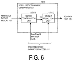
- FIG. 6 is a schematic diagram illustrating a configuration of an inter prediction image generation unit 1011 included in the prediction image generation unit 101 .
- the inter prediction image generation unit 1011 is configured to include a motion compensation unit 10111 and a weight prediction unit 10112 . Descriptions about the motion compensation unit 10111 and the weight prediction unit 10112 are omitted since the motion compensation unit 10111 and the weight prediction unit 10112 have configurations similar to each of the above-mentioned motion compensation unit 3091 and weight prediction unit 3094 , respectively.
- the prediction image generation unit 101 generates the prediction image P of a PU, based on a pixel value of a reference block read from the reference picture memory, by using a parameter input by the prediction parameter encoder.
- the prediction image generated by the prediction image generation unit 101 is output to the subtraction unit 102 and the addition unit 106 .
- the subtraction unit 102 subtracts a signal value of the prediction image P of a PU input from the prediction image generation unit 101 from a pixel value of a corresponding PU of the image T, and generates a residual signal.
- the subtraction unit 102 outputs the generated residual signal to the DCT and quantization unit 103 .
- the DCT and quantization unit 103 performs a DCT for the residual signal input from the subtraction unit 102 , and calculates DCT coefficients.
- the DCT and quantization unit 103 quantizes the calculated DCT coefficients to calculate quantization coefficients.
- the DCT and quantization unit 103 outputs the calculated quantization coefficients to the entropy encoder 104 and the inverse quantization and inverse DCT unit 105 .
- quantization coefficients are input from the DCT and quantization unit 103
- coding parameters are input from the prediction parameter encoder 111 .
- input coding parameters include codes such as a reference picture index refldxLX, a prediction vector index mvp_LX_idx, a difference vector mvdLX, a prediction mode predMode, and a merge index merge_idx.
- the entropy encoder 104 performs entropy coding on the input quantization coefficients and coding parameters to generate the coding stream Te, and outputs the generated coding stream Te to the outside.
- the inverse quantization and inverse DCT unit 105 performs inverse quantization on the quantization coefficients input from the DCT and quantization unit 103 to calculate DCT coefficients.
- the inverse quantization and inverse DCT unit 105 performs inverse DCT on the calculated DCT coefficient to calculate residual signals.
- the inverse quantization and inverse DCT unit 105 outputs the calculated residual signals to the addition unit 106 .
- the addition unit 106 adds signal values of the prediction image P of the PUs input from the prediction image generation unit 101 and signal values of the residual signals input from the inverse quantization and inverse DCT unit 105 for each pixel, and generates the decoded image.
- the addition unit 106 stores the generated decoded image in the reference picture memory 109 .
- the loop filter 107 performs a deblocking filter, a sample adaptive offset (SAO), and an adaptive loop filter (ALF) to the decoded image generated by the addition unit 106 .
- SAO sample adaptive offset
- ALF adaptive loop filter
- the prediction parameter memory 108 stores the prediction parameters generated by the coding parameter determination unit 110 for each picture and CU of the coding target in a prescribed position.
- the reference picture memory 109 stores the decoded image generated by the loop filter 107 for each picture and CU of the coding target in a prescribed position.
- the coding parameter determination unit 110 selects one set among multiple sets of coding parameters.
- a coding parameter is the above-mentioned prediction parameter or a parameter to be a target of coding generated associated with the prediction parameter.
- the prediction image generation unit 101 generates the prediction image P of the PUs by using each of the sets of these coding parameters.
- the coding parameter determination unit 110 calculates cost values indicating a volume of an information quantity and coding errors for each of the multiple sets. For example, a cost value is a sum of a code amount and a value of multiplying a coefficient ⁇ by a square error.
- the code amount is an information quantity of the coding stream Te obtained by performing entropy coding on a quantization error and a coding parameter.
- the square error is a sum of pixels for square values of residual values of residual signals calculated in the subtraction unit 102 .
- the coefficient ⁇ is a real number that is larger than a pre-configured zero.
- the coding parameter determination unit 110 selects a set of coding parameters by which the calculated cost value is minimized.
- the entropy encoder 104 outputs the selected set of coding parameters as the coding stream Te to the outside, and does not output sets of coding parameters that are not selected.
- the coding parameter determination unit 110 stores the determined coding parameters in the prediction parameter memory 108 .
- the prediction parameter encoder 111 derives a format for coding from parameters input from the coding parameter determination unit 110 , and outputs the format to the entropy encoder 104 .
- a derivation of a format for coding is, for example, to derive a difference vector from a motion vector and a prediction vector.
- the prediction parameter encoder 111 derives parameters necessary to generate a prediction image from parameters input from the coding parameter determination unit 110 , and outputs the parameters to the prediction image generation unit 101 .
- parameters necessary to generate a prediction image are a motion vector of a subblock unit.
- the inter prediction parameter encoder 112 derives inter prediction parameters such as a difference vector, based on prediction parameters input from the coding parameter determination unit 110 .
- the inter prediction parameter encoder 112 includes a partly identical configuration to a configuration by which the inter prediction parameter decoder 303 (see FIG. 5 and the like) derives inter prediction parameters, as a configuration to derive parameters necessary for generation of a prediction image output to the prediction image generation unit 101 .
- a configuration of the inter prediction parameter encoder 112 will be described later.
- the intra prediction parameter encoder 113 derives a format for coding (for example, MPM_idx, rem_intra_luma_pred_mode, and the like) from the intra prediction mode IntraPredMode input from the coding parameter determination unit 110 .
- a format for coding for example, MPM_idx, rem_intra_luma_pred_mode, and the like
- FIGS. 7A to 7F are diagrams illustrating splits of a coding node (CN, block) in the image decoding apparatus 31 .
- the image decoding apparatus 31 splits a coding tree unit or a CN by quad tree split (QT split), binary tree split (BT split), or ternary tree split (TT split).
- QT split quad tree split
- BT split binary tree split
- TT split ternary tree split
- the image decoding apparatus 31 splits the coding tree unit or the CN into Coding Units (CUs), each of which is a basic unit of coding processing.
- FIG. 7A illustrates QT split of a block.
- FIG. 7B illustrates an example in which a block is split by BT split in the horizontal direction (HOR).
- FIG. 7C illustrates an example in which a block is split by BT split in the vertical direction (VER). As illustrated in FIGS. 7B and 7C , according to BT split, a side of a block to be split is split in 1:1.
- FIG. 7D illustrates an example in which a block is not split.
- FIG. 7E illustrates an example in which a block is split by TT split in the horizontal direction (HOR).
- FIG. 7F illustrates an example in which a block is split by TT split in the vertical direction (VER). According to TT split, a side of a block to be split is split in 1:2:1.
- horizontal split refers to directions of split lines. Therefore, “horizontal split,” “split in the horizontal direction (HOR),” and “to split horizontally” refer to splitting with respect to a horizontal boundary line, i.e., splitting into two blocks adjoining in the vertical direction. “Vertical split,” “split in the vertical direction (VER),” and “to split vertically” refer to splitting with respect to a vertical boundary line, i.e., splitting into two blocks adjoining in the horizontal direction.
- the horizontal split used herein may be referred to as vertical split (split vertically) because one block is split into two or more blocks adjoining in the vertical direction.
- the vertical split used herein may be referred to as horizontal split (split horizontally) because one block is split into two or more blocks adjoining in the horizontal direction.
- description of vertical split used as in the above-mentioned another usage of the terms may mean horizontal split used herein (or vice versa). In this case, the terms should be interpreted as appropriate so that the terms carry their intended meaning.
- FIG. 8 is a diagram illustrating signaling of tree types performed by the image decoding apparatus 31 .
- the image decoding apparatus 31 repeats quad tree (Quad-tree) split on a CTU or a CN to perform region-tree (RT) split. After that, in a case that the image decoding apparatus 31 detects a flag of Partition Tree (PT) split (BT split or TT split), the image decoding apparatus 31 determines whether to horizontally split a block or to vertically split a block. After that, the image decoding apparatus 31 determines whether the split is BT split or TT split, and then splits the block.
- PT Partition Tree
- FIGS. 53A to 53G and FIGS. 54A to 54D are diagrams illustrating other examples of splits of a coding node (CN, block) in the image decoding apparatus 31 .
- the image decoding apparatus 31 splits a coding tree unit or a CN by Multi Nine Tree split (MNT split), Multi Five Tree split (MFT split), Directional Quad Tree split (Derectional Quad Tree split, DQT split), Directional Five Tree split (DFT split), or Directional Asymmetric Quad Tree split (DAQT split).
- MNT split Multi Nine Tree split
- MFT split Multi Five Tree split
- DQT split Directional Quad Tree split
- DFT split Directional Five Tree split
- DFT split Directional Asymmetric Quad Tree split
- DAQT split Directional Asymmetric Quad Tree split
- FIG. 53A illustrates MNT split of a block.
- FIG. 53B illustrates an example of MFT split of a block
- FIG. 53C illustrates another example of MFT split of a block.
- FIG. 53D illustrates an example of DQT split of a block
- FIG. 53E illustrates another example of DQT split of a block.
- FIG. 53F illustrates an example of DFT split of a block
- FIG. 53G illustrates another example of DFT split of a block.
- FIG. 54A illustrates a first example of DAQT split of a block
- FIG. 54B illustrates a second example of DAQT split of a block
- FIG. 54C illustrates a third example of DAQT split of a block
- FIG. 54D illustrates a fourth example of DAQT split of a block.
- the various split modes described above are classified into an MT split mode group (MT split) and a PT split mode group (PT split).
- MT split MT split mode group
- PT split PT split mode group
- MT split includes at least QT split
- PT split includes at least BT split
- split in which the number of partitions is four or more is classified into MT split, and split in which the number of partitions is three or less is classified into PT split.
- MT split includes at least any of MNT split, MFT split, DQT split, DFT split, and DAQT split, besides QT split, and PT split includes BT split.
- PT split may include TT split.
- the present embodiment employs the following configuration. That is, there are two or more splits in each of which the number of partitions is four or more, and in addition, one of the above-mentioned splits in each of which the number of partitions is four or more is QT split.
- an image decoding apparatus is an image decoding apparatus that decodes a picture for each coding tree unit.
- the image decoding apparatus includes a split unit configured to split a coding node of the coding tree unit.
- the split unit includes, as a split method of splitting a target node into four or more nodes (in a case that a target node is a square), a split mode of splitting a target node into square nodes, and a split mode of splitting a target node into nodes including a rectangular node.
- the split unit splits a target node into four or more nodes including a rectangular node.
- splitting a target node into square nodes refers to splitting in which a target node is split into nodes consisting only of square nodes, in a case that an immediately higher node is a square.
- QT split falls under this case.
- QT split may be referred to as non-directional split, because a square is not directional.
- splitting a target node into nodes including a rectangular node refers to splitting in which a target node is split into nodes including a rectangular node, in a case that an immediately higher node is a square.
- the split nodes may include a square node, on a condition that the split nodes include a rectangular node.
- DQT split, DFT split, and DAQT split fall under this example.
- DQT split, DFT split, and DAQT split are referred to as directional split, because long sides of rectangles split by DQT split, DFT split, and DAQT split all have the same direction.
- the image decoding apparatus 31 decodes MT information indicating MT split and PT information indicating PT split to specify which split mode is to be applied to a split target CN.
- a configuration capable of TT split as in the present embodiment has more split patterns of a block, which is achieved by combinations of splits. Therefore, more time is required to determine a split pattern of a block in the image coding apparatus 11 . For example, to obtain the same split pattern, multiple split processes may occur.
- FIG. 9 illustrates an example in which the same split pattern is obtained through different split processes (example of redundant split). As illustrated in FIG.
- a split pattern obtained in a manner in which a block (for example, a CTU) is horizontally split by TT split and then the middle block obtained by the TT split is further horizontally split by BT split and a split pattern obtained in a manner in which a block is horizontally split by BT split and then each of two blocks obtained by the BT split is further horizontally split by BT split, have the same split pattern.
- the image coding apparatus 11 and the image decoding apparatus 31 according to the present embodiment restrict redundant split of a block. According to the configuration described above, the image coding apparatus 11 no longer needs to evaluate the same split pattern multiple times. Because redundant split is prohibited, coded data, such as a flag related to the split, is no longer required. Therefore, coding efficiency of the image coding apparatus 11 is enhanced.
- FIG. 10 illustrates a block diagram illustrating a configuration of the image decoding apparatus 31 according to the present embodiment.
- some members included in the block diagram illustrated in FIG. 10 are omitted.
- members having the same function as the members illustrated in FIG. 5 are denoted by the same reference signs, and descriptions thereof will be omitted.
- the image decoding apparatus 31 includes a decoding module 9 , a CN information decoder 10 (split information decoder, split unit), a prediction image generation unit 308 , an inverse quantization and inverse DCT unit 311 , a reference picture memory 306 , an addition unit 312 , a loop filter 305 , a header decoder 19 , and a CU decoder 20 .
- the CU decoder 20 further includes a PU information decoder 12 and a Transform Tree (TT) information decoder 13 .
- the TT information decoder 13 further includes a TU decoder 22 .
- the decoding module 9 performs decoding processing of decoding syntax values from binary data. More specifically, the decoding module 9 decodes syntax values coded by an entropy coding scheme such as CABAC, based on coded data and a syntax type supplied from sources of supply. Then, the decoding module 9 returns decoded syntax values to the sources of supply.
- an entropy coding scheme such as CABAC
- sources of supply of coded data and a syntax type are the CN information decoder 10 and the CU decoder 20 (the PU information decoder 12 and the TT information decoder 13 ).
- the header decoder 19 decodes a video parameter set (VPS), an SPS, a PPS, and a slice header of coded data input from the image coding apparatus 11 .
- VPS video parameter set
- SPS SPS
- PPS PPS
- the CN information decoder 10 uses the decoding module 9 to perform decoding processing of a coding tree unit (for each coding tree unit) and coding nodes, for coded data input from the image coding apparatus 11 . Specifically, the CN information decoder 10 decodes CTU information and CN information from coded data, according to the following procedure.
- the CN information decoder 10 uses the decoding module 9 to decode a tree unit header CTUH from CTU information included in a CTU.
- the CN information decoder 10 decodes, from CN information included in a CN, a QT split flag indicating whether or not a target CN is to be split by QT split, a PT split flag indicating whether or not a target CN is to be split by BT split or TT split, a split direction flag indicating a split direction of the BT split or the TT split, and a split mode selection flag indicating a split method of PT split (BT split or TT split).
- the CN information decoder 10 recursively splits and decodes a target CN until a QT split flag and a PT split flag no longer notify of further split.
- the CN information decoder 10 decodes an MT split flag indicating whether or not a target CN is to be split by MT split, a PT split flag indicating whether or not a target CN is to be split by PT split, and a split direction flag indicating a split direction of the MT split or the PT split.
- the CN information decoder 10 recursively splits and decodes a target CN until an MT split flag and a PT split flag no longer notify of further split.
- the CN information decoder 10 decodes a tree unit footer CTUF from the CTU information.
- the tree unit header CTUH and the tree unit footer CTUF include coding parameters referred to by the image decoding apparatus 31 to determine a decoding method of a target coding tree unit.
- the CN information may include parameters applied to a target CN and to a lower or higher coding node, besides a QT split flag, a PT split flag, a split direction flag, a split mode selection flag indicating a split method of PT split (BT split or TT split), and an MT split mode selection flag indicating a split method of MT split.
- the CU decoder 20 includes the PU information decoder 12 and the TT information decoder 13 , and decodes PUI information and TTI information of the lowest coding node CN (i.e., CU).
- the PU information decoder 12 uses the decoding module 9 to decode PU information (such as a merge flag (merge_flag), a merge index (merge_idx), a prediction motion vector index (mvp_idx), a reference image index (ref_idx), an inter prediction indicator (inter_pred_flag), and a difference vector (mvd)) of each PU.
- PU information such as a merge flag (merge_flag), a merge index (merge_idx), a prediction motion vector index (mvp_idx), a reference image index (ref_idx), an inter prediction indicator (inter_pred_flag), and a difference vector (mvd)
- PU information such as a merge flag (merge_flag), a merge index (merge_idx), a prediction motion vector index (mvp_idx), a reference image index (ref_idx), an inter prediction indicator (inter_pred_flag
- the TT information decoder 13 uses the decoding module 9 to decode each TTI (such as TU split flag SP_TU (split_transform_flag) and a CU residual flag CBP_TU (cbf_cb, cbf_cr, cbf_luma), and a TU).
- each TTI such as TU split flag SP_TU (split_transform_flag) and a CU residual flag CBP_TU (cbf_cb, cbf_cr, cbf_luma), and a TU).
- the TT information decoder 13 includes the TU decoder 22 .
- the TU decoder 22 decodes QP update information (quantization correction value).
- the QP update information is a value indicating a difference value from a quantization parameter prediction value qPpred, which is a prediction value of a quantization parameter QP.
- the TU decoder 22 decodes a quantization prediction residual (residual_coding).
- FIG. 11 is a flowchart illustrating QT information decoding processing of the CN information decoder 10 according to one embodiment of the present invention.
- FIG. 12 is a diagram illustrating a configuration example of a syntax table of QT information according to one embodiment of the present invention.
- CN information decoding S 1400 performed by the CN information decoder 10 , QT information decoding and BT information or TT information (BT/TT information) decoding are performed.
- the QT information decoding performed by the CN information decoder 10 will be described below in sequence.
- the CN information decoder 10 decodes CN information from coded data, and recursively decodes Coding Nodes (CNs). Specifically, the CN information decoder 10 decodes QT information, and decodes a target coding tree coding_quadtree(x0, y0, log 2CbSize, cqtDepth). Note that x0, y0 represent top left coordinates of a target coding node. log 2CbSize represents a logarithm CN size (for example, 6, 7, and 8 in a case that a CN size is 64, 128, and 256, respectively).
- the logarithm CN size is the logarithm of a CN size, which is a size of a coding node, to base 2 .
- the logarithm of a size X to base 2 is referred to as a “logarithm X size.”
- cqtDepth represents a CN hierarchy level (QT depth) indicating a level of hierarchy of a coding node.
- the CN information decoder 10 determines whether or not decoded CN information includes a QT split flag. Specifically, the CN information decoder 10 determines whether or not the logarithm CN size log 2CbSize is larger than a logarithm value MinCbLog2SizeY of a prescribed minimum CN size. In a case that the logarithm CN size log 2CbSize is larger than MinCbLog2SizeY, the CN information decoder 10 determines that there is a QT split flag, and the processing proceeds to S 1421 . In other cases, the processing proceeds to S 1422 .
- the CN information decoder 10 determines that the logarithm CN size log 2CbSize is larger than MinCbLog2SizeY, the CN information decoder 10 decodes the QT split flag (split_cu_flag), which is a syntax element.
- the CN information decoder 10 omits decoding of a QT split flag split_cu_flag from the coded data, and derives a QT split flag split_cu_flag as 0.
- the CN information decoder 10 performs QT split. Specifically, the CN information decoder 10 decodes four coding nodes CN of a logarithm CN size log 2CbSize—1, at positions of a CN hierarchy level cqtDepth+1 (x0, y0), (x1, y0), (x0, y1), (x1, y1).
- x0, y0 represent top left coordinates of a target coding node.
- x1, y1 are derived by adding 1 ⁇ 2 of a CN size (1 ⁇ log 2CbSize) to (x0, y0), as in the following equations.
- x 1 x 0+(1 ⁇ (log 2CbSize ⁇ 1))
- y 1 y 0+(1 ⁇ (log 2CbSize ⁇ 1))
- the CN information decoder 10 adds 1 to the CN hierarchy level cqtDepth indicating a level of hierarchy of a coding node to update the CN hierarchy level cqtDepth, and subtracts 1 from the logarithm CN size log 2CbSize, which is a logarithm value of a coding unit size, (divides the CN size by two) to update the logarithm CN size log 2CbSize.
- the CN information decoder 10 continues QT information decoding starting from S 1411 , by using updated top left coordinates, logarithm CN size, and CN hierarchy level.
- the CN information decoder 10 refers to a method of splitting an immediately higher node, which is a node one generation higher than a target node, to restrict a method of splitting the target node.
- a block (CN) as a split target is referred to as a split target block or a target block, and an immediately higher block of the split target block is referred to as a higher block.
- the description below illustrates an example in which the CN information decoder 10 refers to a higher block to restrict a split pattern of a split target block.
- the CN information decoder 10 may refer to a split target block to restrict a split pattern of an immediately lower block.
- FIG. 13A to FIG. 15D illustrate examples of split patterns restricted by the CN information decoder 10 . Note that the solid line in FIG. 13A to FIG.
- 15D denotes a boundary between coding nodes (blocks) generated by splitting a higher coding node or a coding tree unit (higher block).
- the term “DIVISION ALLOWED” means that split indicated by the straight dotted line is possible in a split target block.
- the term “DIVISION RESTRICTED” means that split indicated by the straight dotted line is restricted (prohibited) in a split target block.
- the CN information decoder 10 restricts (prohibits) split of the middle split target block, which is generated by splitting a higher block by TT split, by BT split in a direction the same as a split direction of the higher block.
- the CN information decoder 10 restricts split of the target block by binary tree split in a direction the same as a direction of the ternary tree split performed on the higher block.
- the CN information decoder 10 restricts (prohibits) split of both blocks, which are generated by splitting a higher block by BT split, by BT split in a direction the same as a split direction of the higher block. In other words, in only one of blocks generated by splitting a higher block, BT split in a direction the same as a split direction of the higher block is possible.
- the CN information decoder 10 refers to a split direction of the block processed first, and determines whether or not split of the block to be processed later is subject to restriction.
- the restriction described above may also be expressed as follows.
- a target block is one of two blocks obtained by performing binary tree split on a higher target block and that the other block out of the two blocks is split by binary tree split in a direction the same as a direction of the binary tree split performed on the higher block
- the CN information decoder 10 restricts split of the target block by binary tree split in a direction the same as the direction of the binary tree split performed on the higher block.
- the CN information decoder 10 restricts (prohibits) split of any one of blocks, which are generated by splitting a higher block by BT split, by BT split in a direction the same as a split direction of the higher block.
- a block subject to restriction of split may be a block on which split processing is to be performed later, out of two blocks generated by splitting a higher block.
- the CN information decoder 10 restricts split of the target block by binary tree split in a direction the same as a direction of the binary tree split performed on the higher block.
- the CN information decoder 10 restricts (prohibits) split of all blocks, which are generated by splitting a higher block by TT split, by BT split in a direction different from a direction of the higher block.
- BT split in a direction different from a split direction of the higher block is possible.
- split directions of other blocks generated by the split of the higher block are referred to, and whether or not split of the block on which split processing is to be performed last is subject to restriction is determined.
- the present restriction may also be expressed as follows.
- a target block is one of three blocks obtained by performing ternary tree split on a higher block and that the other two blocks out of the three blocks are split by binary tree split in a direction different from a direction of the ternary tree split performed on the higher block
- the CN information decoder 10 restricts split of the target block by binary tree split in a direction different from the direction of the ternary tree split performed on the higher block.
- the CN information decoder 10 restricts (prohibits) split of any one of blocks, which are generated by splitting a higher block by TT split, by BT split in a direction different from a split direction of the higher block.
- a block subject to restriction of split may be a block on which split processing is to be performed last, out of blocks generated by splitting a higher block.
- the CN information decoder 10 restricts split of the target block by binary tree split in a direction different from a direction of the ternary tree split performed on the higher block.
- the CN information decoder 10 restricts (prohibits) split of both blocks, which are generated by splitting a higher block by BT split, by TT split in a direction different from a split direction of the higher block. In other words, in only one of blocks generated by splitting a higher block, TT split in a direction different from a split direction of the higher block is possible.
- the present restriction may also be expressed as follows.
- a target block is one of two blocks obtained by performing binary tree split on a higher block and that the other block out of the two blocks is split by ternary tree split in a direction different from a direction of the binary tree split performed on the higher block
- the CN information decoder 10 restricts split of the target block by ternary tree split in a direction different from the direction of the binary tree split performed on the higher block.
- the CN information decoder 10 restricts (prohibits) split of any one of blocks, which are generated by splitting a higher block by BT split, by TT split in a direction different from a split direction of the higher block.
- a block subject to restriction of split may be a block on which split processing is to be performed later, out of two blocks generated by splitting a higher block.
- the CN information decoder 10 restricts split of the target block by ternary tree split in a direction different from a direction of the binary tree split performed on the higher block.
- the CN information decoder 10 restricts (prohibits) split of all blocks, which are generated by splitting a higher block by TT split, by TT split in a direction different from a split direction of the higher block. In other words, in two blocks out of three blocks generated by splitting a higher block, TT split in a direction different from a split direction of the higher block is possible.
- the CN information decoder 10 may restrict (prohibit) the split in only either the horizontal direction or the vertical direction.
- the present restriction may also be expressed as follows.
- a target block is one of three blocks obtained by performing ternary tree split on a higher block and that the other two blocks out of the three blocks are split by ternary tree split in a direction different from a direction of the ternary tree split performed on the higher block
- the CN information decoder 10 restricts split of the target block by ternary tree split in a direction different from the direction of the ternary tree split performed on the higher block.
- the CN information decoder 10 restricts (prohibits) split of any one of blocks, which are generated by splitting a higher block by TT split, by TT split in a direction different from a split direction of the higher block.
- a block subject to restriction of split may be a block on which split processing is to be performed last, out of blocks generated by splitting a higher block.
- the CN information decoder 10 restricts split of the target block by ternary tree split in a direction different from a direction of the ternary tree split performed on the higher block.
- FIG. 16 is a flowchart illustrating an overview of an example of a flow of BT/TT information decoding processing of the CN information decoder 10 .
- the CN information decoder 10 determines whether or not a target block can be split by PT split, based on a size of the target block or the like, and then determines whether or not decoding of a PT split flag is required (S 1501 : PT split flag determination). In a case that decoding of a PT split flag is “required” (YES in S 1501 ), the CN information decoder 10 decodes the PT split flag (S 1502 ). Subsequently, the CN information decoder 10 determines whether or not the decoded PT split flag is 0 (S 1503 ).
- the processing ends.
- the CN information decoder 10 determines whether or not a split direction is uniquely determined based on restriction on split of a block that has a configured split direction of a split target block, for example, and performs determination as to whether or not decoding of a split direction flag is required (S 1504 : split direction flag determination).
- the CN information decoder 10 decodes the split direction flag (S 1505 ), and determines a split direction. The processing proceeds to S 1506 .
- the CN information decoder 10 does not decode the split direction flag. The processing proceeds to S 1506 .
- the CN information decoder 10 determines whether or not a split mode of a split target block (TT split, BT split) is uniquely determined based on restriction on split of a block that has a configured split mode, for example, and determines whether or not decoding of a split mode selection flag is required (S 1506 : split mode selection flag determination). In a case that decoding of a split mode selection flag is “required” (in a case that a split mode is not uniquely determined, for example) (YES in S 1506 ), the CN information decoder 10 decodes the split mode selection flag (S 1507 ), and determines a split mode. The processing proceeds to S 1508 .
- the CN information decoder 10 does not decode the split mode selection flag.
- the processing proceeds to S 1508 .
- the CN information decoder 10 splits the split target block according to the determined direction and the determined split mode (S 1508 ).
- the CN information decoder 10 performs loop processing of repeatedly performing BT/TT information decoding processing on blocks generated by the split (S 1509 , S 1510 , S 1511 ). The processing ends after the loop processing ends.
- PT Split Flag Determination Decoding of PT Split Flag, Determination as to Whether or Not Split Is Required Based on PT Split Flag
- FIG. 17A is a diagram illustrating an example of a pseudocode representing PT split flag determination processing
- FIG. 17B is a diagram illustrating an example of a pseudocode representing decoding processing of a PT split flag.
- the CN information decoder 10 determines that PT split is possible, and determines that decoding of a PT split flag split_pt_flag is “required” (TRUE). Subsequently, as illustrated in FIG.
- the CN information decoder 10 decodes the PT split flag split_pt_flag, and determines whether or not PT split is required based on the split_pt_flag. In a case that split is not possible in either BT split or TT split, the CN information decoder 10 determines that decoding of a PT split flag split_pt_flag is “not required” (FALSE). BT split possibility determination and TT split possibility determination will be described later in detail. Note that, in this processing, BTAvailable or TTAvailable to be configured may be called from another subroutine in BT/TT split information decoding processing, and may be able to be referred to.
- FIG. 18A is a diagram illustrating an example of a pseudocode representing BT split possibility determination processing in a case that there are no restricted split patterns described above.
- the CN information decoder 10 derives minPTSize (unit size) indicating a minimum value of a size of a CU.
- minPTSize unit size
- the CN information decoder 10 performs BT split possibility determination, with reference to condition 1 to condition 3 described below.
- cptDepth indicating a level of hierarchy of a split target block is less than maxPTDepth (cptDepth ⁇ maxPTDepth).
- another method may be used in which one is added to a value of Depth of a higher block.
- the CN information decoder 10 determines that BT split is possible (TRUE). In a case that not all of conditions 1 to 3 described above are satisfied, the CN information decoder 10 determines that BT split is not possible (FALSE).
- FIG. 18B is a diagram illustrating an example of a pseudocode representing BT split possibility determination processing in a case that there is a restricted split pattern described above.
- the CN information decoder 10 determines that BT split is possible (TRUE) in a case that BT split possibility determination_additional condition is satisfied in addition to conditions 1 to 3 described above.
- TRUE BT split possibility determination_additional condition
- the BT split possibility determination_additional condition differs depending on a restricted split pattern. Details of the BT split possibility determination_additional condition will be described later.
- FIG. 19A is a diagram illustrating an example of a pseudocode representing TT split possibility determination processing in a case that there are no restricted split patterns described above.
- the CN information decoder 10 derives minPTSize (unit size) indicating a minimum value of a size of a CU.
- minPTSize unit size
- the CN information decoder 10 performs TT split possibility determination, with reference to condition 1 to condition 3 described below.
- cptDepth indicating a level of hierarchy of a split target block is less than maxPTDepth (cptDepth ⁇ maxPTDepth).
- the CN information decoder 10 determines that TT split is possible (TRUE). In a case that not all of conditions 1 to 3 described above are satisfied, the CN information decoder 10 determines that TT split is not possible (FALSE).
- FIG. 19B is a diagram illustrating an example of a pseudocode representing TT split possibility determination processing in a case that there is a restricted split pattern described above.
- the CN information decoder 10 determines that TT split is possible (TRUE) in a case that TT split possibility determination_additional condition is satisfied in addition to conditions 1 to 3 described above.
- the TT split possibility determination_additional condition differs depending on a restricted split pattern. Details of the BT split possibility determination_additional condition will be described later.
- the CN information decoder 10 refers to a doubled size of a minimum size that is referred to for determining whether or not a target block can be split by binary tree split to determine whether or not the target block can be split by ternary tree split.
- a code amount of a PT split flag and a split mode selection flag can be reduced. Therefore, coding efficiency is improved.
- using a doubled size of a value that is used to determine BT split allows a minimum size of a block after splitting to be the same size in both BT split and TT split. Therefore, the processing can be shared by BT split and TT split.
- the CN information decoder 10 is configured to use a common depth variable cptDepth (temporary variable) in BT split possibility determination and TT split possibility determination to restrict a level of hierarchy of a block that can be split. Specifically, the CN information decoder 10 uses whether or not a common depth is less than a threshold value maxPTDepth to determine whether or not PT (BT or TT) split is possible.
- cptDepth temporary variable
- the CN information decoder 10 refers to a depth variable common to binary tree split and ternary tree split to restrict split of a target block.
- a level of hierarchy of a block that can be split is restricted, and thus the number of combinations of BT split and TT split can be reduced. Therefore, complexity of coding and decoding can be reduced.
- cptDepth may be derived from the sum of a split depth btDepth of BT split and a split depth ttDepth of TT split. Specifically, the following equation is obtained.
- an initial value of cptDepth may be configured to be 0, and a value of cptDepth of a block generated by splitting a higher block may be configured to be ⁇ value of cptDepth of higher block ⁇ +1 in a case of performing BT split or TT split on a block. Then, CU information decoding processing of a block in an immediately lower level of hierarchy may be continued recursively.
- an initial value of btDepth may be configured to be 0, and a value of btDepth of a block generated by splitting a higher block in a case of performing BT split on a block may be configured to be ⁇ value of btDepth of higher block ⁇ +1.
- An initial value of ttDepth may be configured to be 0, and a value of ttDepth of a block generated by splitting a higher block in a case of performing TT split on a block may be configured to be ⁇ value of btDepth of higher block ⁇ +1.
- an initial value of a depth cptDepth is configured to be 0, and a value of cptDepth of a block generated by split in a case of performing BT split on a block is cptDepth+1.
- a value of cptDepth is configured to be ⁇ value of cptDepth of higher block ⁇ +1.
- a value of cptDepth may be configured to be ⁇ value of cptDepth of higher block ⁇ +2. Then, CU information decoding processing of a block in an immediately lower level of hierarchy may be continued recursively.
- an initial value of btDepth may be configured to be 0, and in a case of performing BT split on a block, a value of btDepth of a block generated by splitting a higher block may be configured to be ⁇ value of btDepth of higher block ⁇ +1.
- A-a1 the CN information decoder 10 restricts (prohibits) split of the middle block, which is generated by splitting a higher block by TT split, by BT split in a direction the same as a split direction of the higher block) will now be described with reference to FIG. 20 .
- FIG. 20 to FIG. 25 are diagrams illustrating examples of additional conditions of BT/TT split possibility determination.
- the CN information decoder 10 may be configured not to call TT split possibility determination_additional condition, or may be configured to always return TRUE to TT split possibility determination_additional condition.
- A-a2 the CN information decoder 10 restricts (prohibits) split of both blocks, which are generated by splitting a higher block by BT split, by BT split in a direction the same as a split direction of the higher block (prohibits split of a block to be processed last in the BT split by BT split in a direction the same as a split direction of the higher block)) will now be described with reference to FIG. 21 .
- the CN information decoder 10 determines that BT split is possible (TRUE).
- the CN information decoder 10 derives siblingHorBTCount indicating the number of times horizontal BT split is used in a block generated by split of the same higher block.
- the CN information decoder 10 determines that the split target block cannot be split by BT split (FALSE).
- the CN information decoder 10 determines that the split target block cannot be split by BT split (FALSE).
- the CN information decoder 10 determines that BT split is possible (TRUE). Note that, in the restricted split pattern (A-a 2 ), a subroutine of TT split possibility determination_additional condition( ) is unnecessary.
- BT split possibility determination_additional condition in the restricted split pattern (A-a2′: the CN information decoder 10 restricts (prohibits) split of any one of blocks, which are generated by splitting a higher block by BT split, by BT split in a direction the same as a split direction of the higher block) is implemented by partly changing the BT split possibility determination_additional condition of the restricted split pattern (A-a2). Specifically, the CN information decoder 10 does not derive siblingHorBTCount/siblingVerBTCount. The CN information decoder 10 does not perform determination regarding a condition using siblingHorBTCount/siblingVerBTCount (determines TRUE).
- an additional condition can be implemented by changing a value of partIdx in the additional condition to a value indicating a block as a target of restriction.
- A-b1 the CN information decoder 10 restricts (prohibits) split of all blocks, which are generated by splitting a higher block by TT split, by BT split in a direction different from a direction of the higher block) will now be described with reference to FIG. 22 .
- the CN information decoder 10 performs restriction on a block on which split processing is to be performed last, out of blocks generated by TT split.
- the CN information decoder 10 determines that BT split is possible (TRUE).
- the CN information decoder 10 determines that the split target block cannot be split by BT split (FALSE).
- the CN information decoder 10 determines that the split target block cannot be split by BT split (FALSE).
- the CN information decoder 10 determines that BT split is possible (TRUE). Note that, in the restricted split pattern (A-b 1 ), a subroutine of TT split possibility determination_additional condition( ) is unnecessary.
- BT split possibility determination_additional condition in the restricted split pattern (A-b1′: the CN information decoder 10 restricts (prohibits) split of any one block of blocks, which are generated by splitting a higher block by TT split, by BT split in a direction different from a split direction of the higher block) is implemented by partly changing the BT split possibility determination_additional condition of the restricted split pattern (A-b1). Specifically, the CN information decoder 10 does not derive siblingHorBTCount/siblingVerBTCount. The CN information decoder 10 does not perform determination regarding a condition using siblingHorBTCount/siblingVerBTCount (determines TRUE). In a case that a block subject to restriction of split is other than a block on which split processing is to be performed last, an additional condition can be implemented by changing a value of partIdx in the additional condition.
- FIGS. 14E to 14H An additional condition of TT split possibility determination for the restricted split pattern illustrated in FIGS. 14E to 14H (A-b2: the CN information decoder 10 restricts (prohibits) split of both blocks, which are generated by splitting a higher block by BT split, by TT split in a direction different from a split direction of the higher block) will now be described with reference to FIG. 24 .
- the CN information decoder 10 performs restriction on a block on which split processing is to be performed last, out of blocks generated by BT split.
- the CN information decoder 10 determines that TT split is possible (TRUE).
- the CN information decoder 10 determines that the split target block cannot be split by TT split (FALSE).
- the CN information decoder 10 determines that the split target block cannot be split by TT split (FALSE).
- the CN information decoder 10 determines that TT split is possible (TRUE). Note that, in the restricted split pattern (A-b2), a subroutine of BT split possibility determination_additional condition( ) is unnecessary.
- TT split possibility determination_additional condition in the restricted split pattern (A-b2′: the CN information decoder 10 restricts (prohibits) split of any one of blocks, which are generated by splitting a higher block by BT split, by TT split in a direction different from a split direction of the higher block) is implemented by partly changing the TT split possibility determination_additional condition of the restricted split pattern (A-b2).
- the CN information decoder 10 does not derive siblingHorBTCount/siblingVerBTCount.
- the CN information decoder 10 does not perform determination regarding a condition using siblingHorBTCount/siblingVerBTCount (determines TRUE).
- an additional condition can be implemented by changing a value of partIdx in the additional condition to a value indicating a block as a target of restriction.
- A-c the CN information decoder 10 restricts (prohibits) split of all blocks, which are generated by splitting a higher block by TT split, by TT split in a direction different from a split direction of the higher block) will now be described with reference to FIG. 25 .
- the CN information decoder 10 performs restriction on a block on which split processing is to be performed last, out of blocks generated by splitting a higher block by TT split.
- the CN information decoder 10 determines that TT split is possible (TRUE).
- the CN information decoder 10 derives siblingVerTTCount.
- the CN information decoder 10 determines that the split target block cannot be split by TT split (FALSE).
- the CN information decoder 10 determines that TT split is possible (TRUE). Note that, in the restricted split pattern (A-c), a subroutine of BT split possibility determination_additional condition( ) is unnecessary.
- TT split possibility determination_additional condition in the restricted split pattern (A-c′: the CN information decoder 10 restricts (prohibits) split of any one block of blocks, which are generated by splitting a higher block by TT split, by TT split in a direction different from a split direction of the higher block) is implemented by partly changing the TT split possibility determination_additional condition of the restricted split pattern (A-c). Specifically, the CN information decoder 10 does not derive siblingVerBTCount. The CN information decoder 10 does not perform determination regarding a condition using siblingVerBTCount (determines TRUE).
- an additional condition can be implemented by changing a value of partIdx in the additional condition to a value indicating a block as a target of restriction.
- FIG. 23 is another pseudocode representing TT split possibility determination processing performed by the CN information decoder 10 .
- the CN information decoder 10 determines that TT split is possible (TRUE).
- the CN information decoder 10 determines that the split target block cannot be split by TT split (FALSE).
- the CN information decoder 10 determines that the split target block cannot be split by TT split (FALSE).
- TRUE is returned in a case that a condition of FALSE does not hold true.
- the CN information decoder 10 restricts split by TT split in a direction different from a direction of the higher block. In other words, the CN information decoder 10 prohibits such TT split that generates split the same as MFT split.
- the CN information decoder 10 restricts split of the target node by TT split in a direction different from a direction of the TT split performed on the immediately higher node. For example, TT split after TT split is prohibited. Particularly, TT split in the middle block of TT split is prohibited.
- the CN information decoder 10 determines that TT split is possible (TRUE).
- the CN information decoder 10 determines that TT split is not possible.
- TRUE is returned in a case that a condition of FALSE does not hold true.
- FIG. 27A is a diagram illustrating an example of a pseudocode representing split direction flag determination processing in a case that there are no restricted split patterns described above.
- the CN information decoder 10 derives minPTSize (unit size) indicating a minimum value of a size of a CU.
- minPTSize unit size
- vertical split of the block is not possible.
- (x0, y0) represents top left coordinates of the split target block.
- the CN information decoder 10 determines that decoding of a split direction flag is necessary (TRUE).
- FIG. 27B is a diagram illustrating an example of a pseudocode representing split direction flag determination processing in a case that there is a restricted split pattern described above.
- the CN information decoder 10 determines that a split direction is specified or determines that decoding of a split direction flag is necessary. The additional conditions differing depending on restricted split patterns will be described later with reference to FIG. 28 to FIG. 31 .
- FIG. 27C is a diagram illustrating an example of a pseudocode representing decoding processing of a split direction flag.
- FIG. 28 to FIG. 31 are diagrams illustrating examples of pseudocodes representing additional conditions of split direction flag determination for restricted split patterns.
- A-a1 the CN information decoder 10 restricts (prohibits) split of the middle block, which is generated by splitting a higher block by TT split, by BT split in a direction the same as a split direction of the higher block) will now be described with reference to FIG. 28 .
- the CN information decoder 10 sets an initial value of horSplitAvailable and verSplitAvailable to be TRUE.
- the CN information decoder 10 determines that decoding of a split direction flag is necessary.
- the CN information decoder 10 determines that decoding of a split direction flag split_dir_flag is necessary. In a case that one of horSplitAvailable and verSplitAvailable is TRUE, the CN information decoder 10 configures split_dir_flag, and determines that decoding of the split_dir_flag is unnecessary (FALSE).
- the CN information decoder 10 sets an initial value of horSplitAvailable and verSplitAvailable to be TRUE.
- the CN information decoder 10 determines that decoding of a split direction flag is necessary.
- the CN information decoder 10 derives siblingHorBTCount.
- the CN information decoder 10 derives siblingHorBTCount.
- horizontal BT split of the split target block is prohibited.
- the CN information decoder 10 derives siblingVerBTCount.
- Processing of the decoder 10 is similar to Post-processing described above, and thus description of the processing is herein omitted.
- A-b1 the CN information decoder 10 restricts (prohibits) split of all blocks, which are generated by splitting a higher block by TT split, by BT split in a direction different from a direction of the higher block) will now be described with reference to FIG. 30 .
- the CN information decoder 10 sets an initial value of horSplitAvailable and verSplitAvailable to be TRUE.
- the CN information decoder 10 determines that decoding of a split direction flag is necessary.
- the CN information decoder 10 derives siblingVerBTCount. In a case that the other two blocks generated by splitting the higher block are split by vertical BT split, vertical BT split of the split target block is prohibited.
- the CN information decoder 10 derives siblingHorBTCount.
- horizontal BT split of the split target block is prohibited.
- the CN information decoder 10 In an additional condition of TT split possibility determination for the restricted split pattern illustrated in FIGS. 14E to 14H (A-b2: the CN information decoder 10 restricts (prohibits) split of both blocks, which are generated by splitting a higher block by BT split, by TT split in a direction different from a split direction of the higher block) and for the restricted split pattern illustrated in FIGS. 15A to 15D (A-c: the CN information decoder 10 restricts (prohibits) split of all blocks, which are generated by splitting a higher block by TT split, by TT split in a direction different from a split direction of the higher block), the CN information decoder 10 returns TRUE without performing anything as illustrated in FIG. 31 .
- This subroutine is called in a case that neither the width nor the height of a split target block is minPTSize. Therefore, even in a case that TT split of a split target block is restricted, BT split remains possible, and thus options of a split direction are not limited. Note that the same holds true for an additional condition of split direction flag determination in A-b2′ and A-c′.
- FIG. 32 illustrates an example of another pseudocode representing split direction flag determination processing.
- a case that a target block is not the middle block of TT split is not subject to restriction of a split direction.
- the CN information decoder 10 determines that TT split is possible (TRUE).
- a case that a target block is the middle block of TT split is subject to restriction so that the middle block can be split only in a direction the same as a direction of a higher block.
- the CN information decoder 10 configures such that a split direction of the middle block of TT split is a direction the same as the direction of the higher block.
- FIG. 33A is a diagram illustrating an example of a pseudocode representing split mode selection flag processing.
- the CN information decoder 10 derives BTAvailable and TTAvailable.
- BTAvailable and TTAvailable are derived earlier in the PT split flag determination processing, and therefore the derived BTAvailable and TTAvailable may be referred to and reused in the present processing.
- Changing the values of BTAvailable and TTAvailable during and after this subroutine affects a result of PT split flag determination, and is thus not allowed.
- the CN information decoder 10 determines as to whether or not decoding of a split mode selection flag is required, in a split mode selection flag determination_additional condition. In a case that only any one of BT split and TT split is possible, the CN information decoder 10 configures a value of a split mode selection flag, and determines that decoding is unnecessary.
- split mode selection flag determination processing and split mode selection flag decoding processing are dependent solely on the PT split flag determination processing. Therefore, after the processing proceeds to YES due to a value of a PT split flag being true, split mode selection flag determination processing and split mode selection flag decoding processing may be performed before the split direction flag determination processing.
- the CN information decoder 10 decodes a PT split flag (common flag) indicating BT split and TT split.
- the CN information decoder 10 decodes a split mode selection flag indicating either BT split or TT split. In a case that a split mode selection flag is not present, the CN information decoder 10 uses TT split possibility as a value of a split mode selection flag.
- the CN information decoder 10 determines that any one of binary tree split for a target block and ternary tree split for a target block is possible, the CN information decoder 10 decodes a common flag indicating binary tree split and ternary tree split.
- the CN information decoder 10 determines that both of binary tree split for a target block and ternary tree split for a target block are possible, the CN information decoder 10 decodes a split mode selection flag indicating either binary tree split or ternary tree split.
- a PT split flag and a split mode selection flag are not decoded.
- a code amount of those flags can be reduced.
- the CN information decoder 10 refers to a depth variable common to binary tree split and ternary tree split to restrict split of a target block.
- a split depth variable btDepth of binary tree split and a split depth variable ttDepth of ternary tree split may be individually derived to restrict split of a target block.
- FIG. 34A is a diagram illustrating an example of a pseudocode representing PT split flag determination processing.
- the CN information decoder 10 determines that PT split is possible, and determines that decoding of a PT split flag split_pt_flag is “required” (TRUE).
- FIG. 34B is a diagram illustrating an example of a pseudocode representing BT split possibility determination processing in a case that there are no restricted split patterns described above with reference to FIG. 13A to FIG. 15D .
- the CN information decoder 10 performs BT split possibility determination, with reference to condition 1 to condition 3 described below.
- btDepth indicating a level of hierarchy of a split target block is less than maxBTDepth (btDepth ⁇ maxBTDepth).
- the CN information decoder 10 determines that BT split is possible (TRUE). In a case that not all of conditions 1 to 3 described above are satisfied, the CN information decoder 10 determines that BT split is not possible (FALSE).
- FIG. 34C is a diagram illustrating an example of a pseudocode representing TT split possibility determination processing in a case that there are no restricted split patterns described above with reference to FIG. 13A to FIG. 15D .
- the CN information decoder 10 performs TT split possibility determination, with reference to condition 1 to condition 3 described below.
- ttDepth indicating a level of hierarchy of a split target block is less than maxTTDepth (ttDepth ⁇ maxTTDepth).
- the CN information decoder 10 determines that TT split is possible (TRUE). In a case that not all of conditions 1 to 3 described above are satisfied, the CN information decoder 10 determines that TT split is not possible (FALSE).
- Determination illustrated in FIG. 34D is the same as determinations illustrated in FIGS. 34A to 34C . Determination illustrated in FIG. 34D is obtained by combining three determinations illustrated in FIGS. 34A to 34C .
- FIG. 35A is a diagram illustrating an example of a pseudocode representing split mode selection flag determination processing.
- BTAvailable and TTAvailable are derived earlier in the PT split flag determination processing, and therefore the derived BTAvailable and TTAvailable may be referred to and reused in the present processing. Changing the values of BTAvailable and TTAvailable during and after this subroutine affects a result of PT split flag determination, and is thus not allowed.
- the CN information decoder 10 determines TRUE.
- FIG. 35B is a diagram illustrating an example of a pseudocode representing PT split mode selection flag determination processing.
- the CN information decoder 10 performs PT split mode selection flag determination, with reference to condition 1 to condition 3 described below.
- btDepth indicating a level of hierarchy of a split target block is less than maxBTDepth
- ttDepth indicating a level of hierarchy of a split target block is less than maxTTDepth (btDepth ⁇ maxBTDepth && ttDepth ⁇ maxTTDepth).
- the CN information decoder 10 determines TRUE. In a case that not all of conditions 1 to 3 described above are satisfied, the CN information decoder 10 determines FALSE.
- maximum split depths maxBTDepth and maxTTDepth may be configured as follows. Three types of restriction examples of maximum split depths are given below.
- a prescribed value (maximum number of times) is configured for a maximum binary tree split depth maxBTDepth and a maximum ternary tree split depth maxTTDepth.
- maxBTDepth the number of times of binary tree splits and the number of times of ternary tree splits can be restricted independently of each other. For example, in a case that the number of times of binary tree splits is restricted to twice, it is sufficient that maxBTDepth be configured to be 2. In a case that the number of times of ternary tree splits is restricted to once, it is sufficient that maxTTDepth be configured to be 1. Specifically, the following equations are obtained.
- a maximum number of times may be configured as follows.
- a relationship between a maximum binary tree split depth maxBTDepth and a maximum ternary tree split depth maxTTDepth is configured. In this manner, a relationship between the number of times of binary tree splits and the number of times of ternary tree splits can be maintained. For example, in a case that it is intended that the number of times of ternary tree splits is reduced to be less than the number of times of binary tree splits, it is sufficient that a relationship be configured to be maxBTDepth>maxTTDepth.
- a maximum value of the sum of a maximum binary tree split depth maxBTDepth and a maximum ternary tree split depth maxTTDepth is configured. In this manner, a maximum number of times of binary tree splits can be restricted, depending on whether ternary tree split is made effective (in a case ternary tree split is made effective, until how deep a maximum ternary tree depth is made effective).
- a maximum number of times maxTTDepth of binary tree split can be configured to be 3.
- a maximum number of times maxTTDepth of binary tree split can be configured to be a value less than 3.
- the configuration can be as follows.
- a maximum binary tree split depth is restricted to 2 or less.
- ternary tree split is present, three consecutive binary tree splits can be prohibited.
- ternary tree split is made effective, a maximum number of times of binary tree splits can be configured to be even smaller.
- a highly complex combination in which both binary tree split and ternary tree split are used many times, can be avoided. Therefore, prohibition of continuous binary tree splits leads to reduction in complexity of coding/decoding of a video.
- a TT split flag occurs highly frequently.
- a split depth variable btDepth of binary tree split and a split depth variable ttDepth of ternary tree split are individually restricted. Consequently, occurrence of TT split flags can be reduced, and coding of a TT split flag can be reduced.
- condition 3 is different from condition 3 of the first example of determination described above.
- BT split possibility determination is performed, with reference to condition 3 described below.
- condition 3 is different from condition 3 of the first example of determination described above.
- TT split possibility determination is performed, with reference to condition 3 described below.
- condition 3 is different from condition 3 of the first example of determination described above.
- split mode selection flag determination is performed, with reference to condition 3 described below.
- btDepth+ttDepth may be expressed by one temporary variable cptDepth.
- btDepth+ttDepth may be expressed by one temporary variable cptDepth.
- PT split flag determination of the third example of determination can be derived from the sum (OR) of BT split possibility determination and TT split possibility determination, similarly to the first example of determination described above.
- BT split possibility determination and TT split possibility determination are as illustrated in FIGS. 36B and 36C , respectively.
- PT split flag determination which is the sum of the BT split possibility determination and the TT split possibility determination, can be described as in FIG. 36D .
- condition 3 is different from condition 3 of the first example of determination described above.
- BT split possibility determination is performed, with reference to condition 3 described below.
- btDepth indicating a level of hierarchy of a split target block is less than maxBTDepth
- (btDepth+ttDepth) indicating a level of hierarchy of a split target block is less than maxPTDepth (btDepth ⁇ maxBTDepth && (btDepth+ttDepth) ⁇ maxPTDepth).
- condition 3 is different from condition 3 of the first example of determination described above.
- TT split possibility determination is performed, with reference to condition 3 described below.
- ttDepth indicating a level of hierarchy of a split target block is less than maxTTDepth
- (btDepth+ttDepth) indicating a level of hierarchy of a split target block is less than maxPTDepth (ttDepth ⁇ maxTTDepth && (btDepth+ttDepth) ⁇ maxPTDepth).
- split mode selection flag determination of the third example of determination can be derived from the product (AND) of BT split possibility determination and TT split possibility determination, similarly to the first example of determination described above.
- BT split possibility determination and TT split possibility determination are as illustrated in FIGS. 36B and 36C , respectively.
- Split mode selection flag determination which is the product of the BT split possibility determination and the TT split possibility determination, can be described as in FIG. 37D .
- a split mode selection flag is present (TRUE), and a split mode selection flag as a flag indicating either BT split or TT split is decoded.
- restriction concerning “width” and “height” of a target block may further be added, in addition to the restriction concerning a level of hierarchy.
- split mode selection flag determination of the third example of determination condition 4 is different, as compared to conditions of the first example of determination described above.
- split mode selection flag determination is performed, with reference to condition 4 described below.
- the CN information decoder 10 determines TRUE. In a case that not all of conditions 1 to 4 described above are satisfied, the CN information decoder 10 determines FALSE.
- both of binary tree split and ternary tree split can be restricted to three times or less (split is possible in a case that btDepth ⁇ 3 and ttDepth ⁇ 3, respectively), and a total number of times obtained by adding the number of times of binary tree splits and the number of times of ternary tree splits can also be restricted to three times or less ((btDepth+ttDepth) ⁇ 3 suffices).
- the following configuration is also possible.
- a total number of times obtained by adding the number of times of binary tree splits and the number of times of ternary tree splits can be restricted to three times or less (split is possible in a case that btDepth+ttDepth ⁇ 3), and ternary tree split can be restricted to twice or less (BT split and TT split can be used in a case that btDepth ⁇ 3 and ttDepth ⁇ 2, respectively).
- a split depth variable btDepth of binary tree split and a split depth variable ttDepth of ternary tree split are individually restricted, and a variable obtained by combining together the split depth variable btDepth of binary tree split and the split depth variable ttDepth of ternary tree split is restricted. Consequently, redundancy control can be performed, and unnecessary increase of binary tree splits can be reduced particularly in a case that ternary tree split is performed.
- FIG. 38A is a diagram illustrating an example of a pseudocode representing split mode selection flag determination processing of restricting binary tree split after ternary tree split.
- the CN information decoder 10 determines that BT split is not possible in a case that TT split has already been performed. Specifically, in a case that a split depth ttDepth of TT split is greater than 0 (other than 0), the CN information decoder 10 determines that BT split is not possible. In a case that BT split and TT split are possible in split mode selection flag determination, the CN information decoder 10 determines that a split mode selection flag is to be decoded (TRUE).
- FIG. 38B is a diagram illustrating an example of a pseudocode representing split mode selection flag determination processing of restricting ternary tree split after binary tree split.
- the CN information decoder 10 determines that TT split is not possible in a case that BT split has already been performed. Specifically, in a case that a split depth btDepth of BT split is greater than 0 (other than 0), the CN information decoder 10 determines that TT split is not possible. In a case that BT split and TT split are possible in split mode selection flag determination, the CN information decoder 10 determines that a split mode selection flag is to be decoded (TRUE).
- the fourth example of determination and the fifth example of determination described above require only simple control, and yet produce an obvious effect of reduction in complexity of coding/decoding of a video.
- FIGS. 39A and 39B are diagrams illustrating examples of pseudocodes representing BT/TT split processing.
- the CN information decoder 10 splits a split target block, based on a split direction flag and a split mode selection flag.
- the CN information decoder 10 also configures information (parent . . . ) indicating which type of split is performed on a higher block to generate a split target block.
- partIdx is an index of a block, and is configured for each loop.
- a caller derives information in advance regarding each block as to whether or not restriction is present and as to whether or not restriction can be applied, and configures the information.
- the image decoding apparatus 31 includes a configuration similar to the configuration of the second embodiment, unless otherwise specifically limited.
- the image decoding apparatus 31 is configured to be capable of TT split, similarly to the image decoding apparatus 31 of the second embodiment. Therefore, there are more split patterns of a block, which is achieved by combinations of splits. Thus, more time is required to determine a split pattern of a block in the image coding apparatus 11 .
- the image decoding apparatus 31 according to the present embodiment restricts (prohibits) a split pattern with low frequency of use.
- FIG. 40 is a diagram illustrating an example of a split pattern with low frequency of use.
- split pattern 1 and split pattern 2 are illustrated.
- Split pattern 1 is obtained by horizontally splitting a block (CN) by TT split, and then further horizontally splitting a block obtained by the TT split by TT split.
- Split pattern 2 is obtained by horizontally splitting a block by TT split, and then further horizontally splitting a block obtained by the TT split by BT split.
- a block generated by two times of TT split in split pattern 1 has too elongated a shape to have high frequency of use. Therefore, the image decoding apparatus 31 restricts (prohibits) split pattern 1 .
- the image coding apparatus 11 no longer needs to evaluate a split pattern with low frequency of use. Because a split pattern with low frequency of use is prohibited, coded data, such as a flag related to the split, is no longer required. Therefore, coding efficiency of the image coding apparatus 11 is enhanced.
- FIGS. 41A to 41C illustrate examples of split patterns restricted by the CN information decoder 10 .
- the solid line in FIGS. 41A to 41C denotes a boundary between coding nodes (blocks) generated by splitting a higher coding node or a coding tree unit (higher block).
- the term “DIVISION ALLOWED” means that split indicated by the dotted line is possible in a split target block.
- DIVISION RESTRICTED means that split indicated by the dotted line is restricted (prohibited) in a split target block.
- the CN information decoder 10 restricts (prohibits) split of a split target block, which is generated by splitting a higher block by TT split, in a direction the same as a split direction of the higher block.
- the CN information decoder 10 restricts split of the target block in a direction the same as a direction of the ternary tree split performed on the higher block.
- the CN information decoder 10 restricts (prohibits) split of the middle block, which is out of blocks generated by splitting a higher block by TT split, in a direction the same as a split direction of the higher block.
- the CN information decoder 10 restricts split of the target block in a direction the same as a direction of the ternary tree split performed on the higher block.
- the CN information decoder 10 restricts (prohibits) split of the middle block, which is out of blocks generated by splitting a higher block by TT split, by split other than TT split performed in a direction different from a split direction of the higher block.
- the CN information decoder 10 restricts split of the target block by split other than ternary tree split with a direction different from a direction of the ternary tree split performed on the higher block.
- the CN information decoder 10 restricts (prohibits) split of a block, which is out of blocks generated by splitting a higher block by TT split and is other than the middle block, in a direction the same as a direction of the higher block.
- the CN information decoder 10 restricts split of the target block in a direction the same as a direction of the ternary tree split performed on the higher block.
- the CN information decoder 10 restricts (prohibits) split of a block, which is generated by splitting a higher block by TT split, by TT split in a direction the same as a split direction of the higher block.
- the split unit restricts split of the target node by ternary tree split in a direction the same as a direction of the ternary tree split performed on the immediately higher node.
- FIG. 42 to FIG. 46B are diagrams illustrating examples of pseudocodes representing additional conditions of split direction flag determination in restricted split patterns.
- a split direction of the split target block is configured to be a direction different from the split direction of the higher block, and it is determined that decoding of a split direction flag is unnecessary (FALSE).
- the split direction (parentSplitDir) of the higher block is 0 or 1. Therefore, as illustrated in FIG. 42 , parentSplitDir is subtracted from 1. In this manner, a direction different from the direction of the higher block can be derived.
- a split direction of the split target block is configured to be a direction different from a split direction of the higher block, and it is determined that decoding of a split direction flag is unnecessary (FALSE).
- a split direction of the split target block is configured to be a direction different from a split direction of the higher block, and it is determined that decoding of a split direction flag is unnecessary (FALSE).
- a split direction of the split target block is configured to be a direction different from a split direction of the higher block, and it is determined that decoding of a split direction flag is unnecessary (FALSE).
- FIG. 45B is a diagram illustrating an example of a pseudocode representing BT split possibility determination processing in a case that there is a restricted split pattern described above.
- FIG. 45C is a diagram illustrating possible splits in the present restriction. As illustrated in FIG. 45C , the CN information decoder 10 restricts BT split of the middle block generated by TT split. Regarding a split direction of the block, a direction the same as a split direction of a higher block is restricted.
- a flow of processing of the CN information decoder 10 for the restricted split pattern (B-d3: the CN information decoder 10 restricts (prohibits) split of a block, which is generated by splitting a higher block by TT split, by TT split in a direction the same as a split direction of the higher block) will now be described.
- FIG. 50 is a diagram illustrating an overview of an example of a flow of processing of the CN information decoder 10 performing the present restriction. As illustrated in FIG. 50 , the flow of the present processing is different from the example of the flow of processing of the CN information decoder 10 described in the second embodiment (see FIG. 16 ) in the following respect. That is, in the present processing, determination of a split mode (split mode selection flag determination S 1506 , split mode selection flag determination S 1507 ) is performed prior to determination of a split direction (split direction flag determination S 1504 , split direction flag decoding S 1505 ).
- split direction flag determination An additional condition of split direction flag determination will now be described with reference to FIGS. 46A and 46B .
- FIG. 46B is a diagram illustrating possible splits in the present restriction. As illustrated in FIG. 46B , only in a case that TT split is selected as split of a target block, the CN information decoder 10 restricts a split direction solely to a direction different from a split direction of a higher block.
- FIGS. 47A to 47L illustrate examples of split patterns restricted by the CN information decoder 10 .
- the CN information decoder 10 restricts (prohibits) split of a rectangular split target block as illustrated in each of FIGS. 47A to 47D , which is out of blocks generated by splitting a higher block by TT split, in a direction the same as a split direction of the higher block as indicated by the dotted line(s) of the drawings.
- the CN information decoder 10 does not restrict a method of splitting the target block.
- the CN information decoder 10 may restrict (prohibit) split of a redundant split pattern described in the second embodiment.
- FIG. 48 is a diagram illustrating an example of a pseudocode representing an additional condition of split direction flag determination for the restricted split pattern (B-e).
- FIGS. 49A and 49B illustrate examples of split patterns restricted by the CN information decoder 10 .
- the CN information decoder 10 restricts split of the target block by such ternary tree split that generates boundaries along a longitudinal direction of the target block.
- An aspect ratio of a block herein refers to a maximum value of a ratio between the width and the height, in a case that the width and the height of the block are respectively represented by “width” and “height.” Specifically, the expression of max(width/height, height/width) is employed.
- Aspect ratio TT split restriction prohibits a ratio between “width” and “height” from being a prescribed value or greater by TT split, e.g., 1:8 (4 ⁇ 32, 8 ⁇ 64) and 8:1 (32 ⁇ 4, 64 ⁇ 8). In other words, in a case that a target block has a shape horizontally long to a certain extent or more, horizontal split is prohibited. In a case that a target block has a shape vertically long to a certain extent or more, vertical split is prohibited.
- FIG. 49A illustrates an example in which the CN information decoder 10 prohibits horizontal split because a target block has a horizontally long shape.
- FIG. 49B illustrates an example in which the CN information decoder 10 prohibits vertical split because a target block has a vertically long shape.
- FIG. 51 is a diagram illustrating an example of a pseudocode representing an additional condition of split direction flag determination in the restricted split pattern. As illustrated in FIG. 51
- TT split is restricted.
- a value of TTAVailable is not configured.
- a value of TTAvailable is not changed either.
- This subroutine is called only in a case that both BTAVailable/TTAVailable are TRUE. Even in a case that falls under the condition described above and a short-side direction is restricted only to BT split, TT split remains possible in a long-side direction. Therefore, a value of TTAvailable is not affected.
- a flow of processing of the CN information decoder 10 for the present restricted split pattern may be the same as the flow of the restricted split pattern (B-d3) illustrated in FIG. 50 .
- the flow of processing illustrated in FIG. 50 is described above, and thus description of the flow of processing illustrated in FIG. 50 is herein omitted.
- An additional condition of split direction flag determination (aspect ratio TT split restriction) in the flow of processing illustrated in FIG. 50 will be described with reference to FIG. 52 .
- FIG. 52 is a diagram illustrating an example of a pseudocode representing an additional condition of split direction flag determination in the restricted split pattern. As illustrated in FIG.
- FIG. 55 is a flowchart illustrating a first example of MT information decoding processing of the CN information decoder 10 according to one embodiment of the present invention.
- FIG. 55 is a flowchart illustrating MT decoding processing in a case that MT split includes MNT split and QT split.
- the CN information decoder 10 determines whether or not an MT split flag is to be decoded (MT split flag determination). In a case that the CN information decoder 10 determines that an MT split flag is to be decoded (MT split flag determination is Y/TRUE), the processing proceeds to Step S 1102 . In a case that the CN information decoder 10 determines that an MT split flag is not to be decoded (MT split flag determination is N/FALSE), the MT information decoding processing ends.
- the CN information decoder 10 performs decoding of an MT split flag mt_split_flag.
- the CN information decoder 10 determines whether the following determination expression concerning the MT split flag mt_split_flag is true or false.
- MT split mode selection flag determination is NO/FALSE
- the CN information decoder 10 decodes the MT split mode selection flag mt_sel_flag.
- the CN information decoder 10 decodes the split target block by a split mode indicated by the MT split mode selection flag mt_sel_flag.
- the CN information decoder 10 splits the target block (target node) in 1:2:1 in the horizontal direction and 1:2:1 in the vertical direction. Consequently, the CN information decoder 10 splits the target block (target node) into nine nodes (blocks). Specifically, the CN information decoder 10 splits the target node in 1:2:1 in a first direction, and in 1:2:1 in a second direction perpendicular to (orthogonal to) the first direction. Consequently, the CN information decoder 10 splits the target node into nine nodes.
- the CN information decoder 10 splits the target block by quad tree split.
- a method of split indicated by MNT split may be implemented by consecutively applying two times of TT split, whose split directions are orthogonal to each other, to the target node.
- the CN information decoder 10 splits the target node into four or more (here, nine) through single split processing. Therefore, increase in split depth (number of times of splits) can be prevented, and at the same time, complex split can be implemented.
- loop processing of repeatedly performing MT information decoding processing on blocks generated by the split is performed (S 1107 , S 1108 , S 1109 ). The processing ends after the loop processing ends.
- FIG. 56A is a diagram illustrating an example of a pseudocode representing MT split flag determination processing
- FIG. 56B is a diagram illustrating an example of a pseudocode representing MT split mode selection flag determination processing.
- the CN information decoder 10 performs MT split flag determination, with reference to condition 1 to condition 3 described below.
- minPTSize represents a minimum value of a block size at the time of PT split.
- maxMTSize represents a maximum value of a block size at the time of MT split.
- qtDepth indicating a level of hierarchy of a split target block is less than maxQTDepth, or mntDepth indicating a level of hierarchy of a split target block is less than maxMNTDepth (qtDepth ⁇ maxQTDepth ⁇ mntDepth ⁇ maxMNTDepth).
- maxQTSize represents a maximum value of a depth (level of hierarchy) at the time of QT split
- maxMNTSize represents a maximum value of a depth (level of hierarchy) at the time of MNT split.
- the CN information decoder 10 determines that MT split is possible (TRUE). In a case that any of conditions 1 to 3 described above is not satisfied, the CN information decoder 10 determines that MT split is not possible (FALSE).
- the CN information decoder 10 performs MT split mode selection flag determination, with reference to condition 1 to condition 3 described below.
- qtDepth indicating a level of hierarchy of a split target block is less than maxQTDepth
- mntDepth indicating a level of hierarchy of a split target block is less than maxMNTDepth (qtDepth ⁇ maxQTDepth && mntDepth ⁇ maxMNTDepth).
- the CN information decoder 10 determines that decoding of an MT split mode selection flag is necessary (TRUE). In a case that any of conditions 1 to 3 described above is not satisfied, the CN information decoder 10 determines that decoding of an MT split mode selection flag is unnecessary (FALSE).
- FIG. 57 is a flowchart illustrating a second example of MT information decoding processing of the CN information decoder 10 according to one embodiment of the present invention.
- the second example of MT information decoding processing is different from the first example of MT information decoding processing described above in the following respect. That is, in the present example, in a case that MT split is performed, decoding processing of a flag (MT split direction flag mt_dir_flag) for distinguishing whether a split direction is the horizontal direction or the vertical direction is performed.
- a flag MT split direction flag mt_dir_flag
- S 1401 to S 1405 correspond to S 1101 to S 1105 of the first example of MT information decoding processing described above
- S 1409 to S 1411 correspond to S 1107 to S 1109 of the first example of MT information decoding processing described above.
- the CN information decoder 10 determines whether or not an MT split direction flag is to be decoded. In a case that the CN information decoder 10 determines that an MT split direction flag is to be decoded, the processing proceeds to S 1407 . In a case that the CN information decoder 10 determines that an MT split direction flag is not to be decoded, the processing proceeds to S 1408 .
- the CN information decoder 10 performs decoding of an MT split direction flag mt_dir_flag.
- order of decoding processing of an MT split mode selection flag mt_sel_flag (S 1404 and S 1405 ) and decoding processing of an MT split direction flag mt_dir_flag (S 1406 and S 1407 ) may be in reverse order.
- the CN information decoder 10 decodes the split target block, based on the MT split direction flag mt_dir_flag and the MT split mode selection flag mt_sel_flag.
- the CN information decoder 10 splits the target block (target node) in 1:2:1 in the horizontal direction to split the target block (target node) into three nodes. Then, the CN information decoder 10 splits the middle node out of the three nodes in 1:2:1 in the vertical direction. Consequently, the CN information decoder 10 splits the target block (target node) into five nodes (blocks).
- the CN information decoder 10 splits the target block (target node) in 1:2:1 in the vertical direction to split the target block (target node) into three nodes. Then, the CN information decoder 10 splits the middle node out of the three nodes in 1:2:1 in the horizontal direction. Consequently, the CN information decoder 10 splits the target block (target node) into five nodes (blocks).
- FIG. 58A is a diagram illustrating an example of a pseudocode representing MT split flag determination processing
- FIG. 58B is a diagram illustrating an example of a pseudocode representing MT split mode selection flag determination processing
- FIG. 58C is a diagram illustrating an example of a pseudocode representing MT split direction flag determination processing.
- MT split flag determination of the second example of MT information decoding processing is different from MT split flag determination of the first example of MT information decoding processing in condition 3.
- Condition 3 of MT split flag determination of the second example of MT information decoding processing is as follows.
- qtDepth indicating a level of hierarchy of a split target block is less than maxQTDepth, or mftDepth indicating a level of hierarchy of a split target block is less than maxMFTDepth (qtDepth ⁇ maxQTDepth ⁇ mftDepth ⁇ maxMFTDepth).
- maxMFTDepth represents a maximum value of a depth (level of hierarchy) at the time of MFT split.
- MT split mode selection flag determination of the second example of MT information decoding processing is different from MT split mode selection flag determination of the first example of MT information decoding processing in condition 3.
- Condition 3 of MT split mode selection flag determination of the second example of MT information decoding processing is as follows.
- Condition 3 qtDepth indicating a level of hierarchy of a split target block is less than maxQTDepth, and mftDepth indicating a level of hierarchy of a split target block is less than maxMFTDepth (qtDepth ⁇ maxQTDepth && mftDepth ⁇ maxMFTDepth).
- the CN information decoder 10 performs MT split direction flag determination, with reference to condition 1 to condition 4 described below.
- the CN information decoder 10 determines that decoding of an MT split direction flag is necessary (TRUE). In a case that any of conditions 1 to 4 described above is not satisfied, the CN information decoder 10 determines that decoding of an MT split direction flag is unnecessary (FALSE).
- the CN information decoder 10 in a case that the CN information decoder 10 performs node split on a node higher than a target node by at least any of BT split and TT split, the CN information decoder 10 does not perform split on the target node by a first split type group, which includes a split type for splitting into five nodes (MFT) and QT split.
- a split type group which includes a split type for splitting into five nodes (MFT) and QT split.
- FIG. 59 is a table illustrating relationships between shapes and each of values of an MT split flag mt_split_flag, an MT split mode selection flag mt_sel_flag, and an MT split direction flag mt_dir_flag.
- the CN information decoder 10 performs split so that QT illustrated in FIG. 7A is implemented.
- the CN information decoder 10 performs split so that MFT HOR illustrated in FIG. 53B (abbreviated as “MFTH” in FIG. 59 ) is implemented.
- an MT split mode selection flag is 1 indicating MT split
- the CN information decoder 10 employs a direction indicated by an MT split direction flag mt_dir_flag as a first direction to split a target node into five nodes.
- a flow of MT information decoding processing of the CN information decoder 10 of the third example of MT information decoding processing is the same as the flow of MT information decoding processing of the CN information decoder 10 of the second example of MT information decoding processing.
- FIG. 60A is a diagram illustrating an example of a pseudocode representing MT split flag determination processing
- FIG. 60B is a diagram illustrating an example of a pseudocode representing MT split mode selection flag determination processing
- FIG. 60C is a diagram illustrating an example of a pseudocode representing MT split direction flag determination processing.
- MT split flag determination of the third example of MT information decoding processing is different from MT split flag determination of the first example of MT information decoding processing in condition 3.
- Condition 3 of MT split flag determination of the third example of MT information decoding processing is as follows.
- Condition 3 qtDepth indicating a level of hierarchy of a split target block is less than maxQTDepth, or dqtDepth indicating a level of hierarchy of a split target block is less than maxDQTDepth (qtDepth ⁇ maxQTDepth ⁇ dqtDepth ⁇ maxDQTDepth).
- MT split mode selection flag determination of the third example of MT information decoding processing is different from MT split mode selection flag determination of the first example of MT information decoding processing in condition 3.
- Condition 3 of MT split mode selection flag determination of the third example of MT information decoding processing is as follows.
- Condition 3 qtDepth indicating a level of hierarchy of a split target block is less than maxQTDepth, and dqtDepth indicating a level of hierarchy of a split target block is less than maxDQTDepth (qtDepth ⁇ maxQTDepth && dqtDepth ⁇ maxDQTDepth).
- maxDQTDepth represents a maximum value of a depth (level of hierarchy) at the time of DQT split.
- MT split direction flag determination of the third example of MT information decoding processing is different from MT split direction flag determination of the second example of MT information decoding processing in conditions 1, 2, and 4.
- Conditions 1, 2, and 4 of MT split direction flag determination of the third example of MT information decoding processing are as follows.
- the CN information decoder 10 performs node split on a node higher than a target node by a split type for splitting into four nodes (DQT)
- the CN information decoder 10 does not perform split on the target node by a split type for splitting into four or more nodes including a rectangular node.
- DQT split is performed even only once
- MT split is not performed after the DQT split.
- FIG. 61 is a table illustrating relationships between shapes and each of values of an MT split flag mt_split_flag, an MT split mode selection flag mt_sel_flag, and an MT split direction flag mt_dir_flag.
- the CN information decoder 10 performs split so that QT illustrated in FIG. 7A is implemented.
- the CN information decoder 10 performs split so that DQT HOR illustrated in FIG. 53E (abbreviated as “DQTH” in FIG. 61 ) is implemented.
- the CN information decoder 10 performs split so that DQT VER illustrated in FIG. 53D (abbreviated as “DQTV” in FIG. 61 ) is implemented.
- the CN information decoder 10 employs a direction indicated by an MT split direction flag as a first direction to split a target node into four nodes.
- a flow of MT information decoding processing of the CN information decoder 10 of the fourth example of MT information decoding processing is the same as the flow of MT information decoding processing of the CN information decoder 10 of the second example of MT information decoding processing.
- FIG. 62A is a diagram illustrating an example of a pseudocode representing MT split flag determination processing
- FIG. 62B is a diagram illustrating an example of a pseudocode representing MT split mode selection flag determination processing
- FIG. 62C is a diagram illustrating an example of a pseudocode representing MT split direction flag determination processing.
- MT split flag determination of the fourth example of MT information decoding processing is different from MT split flag determination of the first example of MT information decoding processing in condition 3.
- Condition 3 of MT split flag determination of the fourth example of MT information decoding processing is as follows.
- Condition 3 qtDepth indicating a level of hierarchy of a split target block is less than maxQTDepth, or dftDepth indicating a level of hierarchy of a split target block is less than maxDFTDepth (qtDepth ⁇ maxQTDepth ⁇ dftDepth ⁇ maxDFTDepth).
- maxDFTDepth represents a maximum value of a depth (level of hierarchy) at the time of DFT split.
- MT split mode selection flag determination of the fourth example of MT information decoding processing is different from MT split mode selection flag determination of the first example of MT information decoding processing in conditions 1 and 3.
- Conditions 1 and 3 of MT split mode selection flag determination of the fourth example of MT information decoding processing are as follows.
- Condition 3 qtDepth indicating a level of hierarchy of a split target block is less than maxQTDepth, and dftDepth indicating a level of hierarchy of a split target block is less than maxDFTDepth (qtDepth ⁇ maxQTDepth && dftDepth ⁇ maxDFTDepth).
- MT split direction flag determination of the fourth example of MT information decoding processing is different from MT split direction flag determination of the third example of MT information decoding processing in conditions 2 and 4.
- Conditions 2 and 4 of MT split direction flag determination of the fourth example of MT information decoding processing are as follows.
- Condition 4 qtDepth indicating a level of hierarchy of a split target block is less than maxQTDepth, and dftDepth indicating a level of hierarchy of a split target block is less than maxDFTDepth (qtDepth ⁇ maxQTDepth && dftDepth ⁇ maxDFTDepth).
- the CN information decoder 10 performs node split on a node higher than a target node by a split type for splitting into five nodes (DFT)
- the CN information decoder 10 does not perform split on the target node by a split type for splitting into four or more nodes including a rectangular node.
- DFT split PT split
- QT split MT split
- FIG. 63 is a table illustrating relationships between shapes and each of values of an MT split flag mt_split_flag, an MT split mode selection flag mt_sel_flag, and an MT split direction flag mt_dir_flag.
- the CN information decoder 10 performs split so that QT illustrated in FIG. 7A is implemented.
- the CN information decoder 10 performs split so that DFT HOR illustrated in FIG. 53G (abbreviated as “DFTH” in FIG. 63 ) is implemented.
- an MT split mode selection flag is 1 indicating DQT split
- the CN information decoder 10 performs split so that DFT VER illustrated in FIG. 53F (abbreviated as “DFTV” in FIG. 63 ) is implemented.
- the CN information decoder 10 employs a direction indicated by an MT split direction flag as a first direction to split a target node into five nodes.
- FIG. 64 is a flowchart illustrating MT information decoding processing of the CN information decoder 10 according to one embodiment of the present invention.
- the MT information decoding processing is different from the second example of MT information decoding processing described above in the following respect. That is, in the present embodiment, in a case that MT split is performed, decoding processing of a flag (MT asymmetric flag mt_amt_flag) for distinguishing an asymmetric pattern is performed.
- S 2201 to S 1407 correspond to S 1401 to S 1407 of the second example of MT information decoding processing described above
- S 2211 to S 2013 correspond to S 1409 to S 1411 of the second example of MT information decoding processing described above.
- the CN information decoder 10 determines whether or not an MT asymmetric flag is to be decoded. In a case that the CN information decoder 10 determines that an MT asymmetric flag is to be decoded, the processing proceeds to S 2209 . In a case that the CN information decoder 10 determines that an MT split MMT flag is not to be decoded, the processing proceeds to S 2210 .
- the CN information decoder 10 performs decoding of an MT asymmetric flag mt_amt_flag.
- the CN information decoder 10 decodes the split target block, based on the MT split mode selection flag mt_sel_flag, the MT split direction flag mt_dir_flag, and the MT asymmetric flag mt_amt_flag.
- FIG. 65A is a diagram illustrating an example of a pseudocode representing MT split flag determination processing
- FIG. 65B is a diagram illustrating an example of a pseudocode representing MT split mode selection flag determination processing
- FIG. 65C is a diagram illustrating an example of a pseudocode representing MT split direction flag determination processing.
- MT split flag determination of the fifth example of MT information decoding processing is different from MT split flag determination of the first example of MT information decoding processing in condition 3.
- Condition 3 of MT split flag determination of the fifth example of MT information decoding processing is as follows.
- qtDepth indicating a level of hierarchy of a split target block is less than maxQTDepth, or daqtDepth indicating a level of hierarchy of a split target block is less than maxDAQTDepth (qtDepth ⁇ maxQTDepth ⁇ daqtDepth ⁇ maxDAQTDepth).
- maxDAQTDepth represents a maximum value of a depth (level of hierarchy) at the time of DAQT split.
- MT split mode selection flag determination of the fifth example of MT information decoding processing is different from MT split mode selection flag determination of the fourth example of MT information decoding processing in condition 3.
- Condition 3 of MT split mode selection flag determination of the fifth example of MT information decoding processing is as follows.
- qtDepth indicating a level of hierarchy of a split target block is less than maxQTDepth
- daqtDepth indicating a level of hierarchy of a split target block is less than maxDAQTDepth (qtDepth ⁇ maxQTDepth && daqtDepth ⁇ maxDAQTDepth).
- MT split direction flag determination of the fifth example of MT information decoding processing is different from MT split direction flag determination of the fourth example of MT information decoding processing in conditions 1 and 4.
- Condition 4 of MT split direction flag determination of the fifth example of MT information decoding processing is as follows.
- the CN information decoder 10 performs node split on a node higher than a target node by a split type for splitting into four nodes (DAQT)
- the CN information decoder 10 does not perform split on the target node by a split type for splitting into four or more nodes including a rectangular node.
- DAQT split is performed even only once
- MT split is not performed after the DAQT split.
- FIG. 66 is a table illustrating relationships between shapes and each of values of an MT split flag mt_split_flag, an MT split mode selection flag mt_sel_flag, an MT split direction flag mt_dir_flag, and an MT asymmetric flag mt_amt_flag.
- the CN information decoder 10 performs split so that QT illustrated in FIG. 7A is implemented.
- an MT split mode selection flag is 1 indicating MT split
- DAQT HOR 0 illustrated in FIG. 54C abbreviated as “DAQTH 0 ” in FIG. 66 ) is implemented.
- an MT split mode selection flag is 1 indicating MT split
- an MT split mode selection flag is 1 indicating MT split
- DAQT VER 0 illustrated in FIG. 54A abbreviated as “DAQTV 0 ” in FIG. 66
- an MT split mode selection flag is 1 indicating MT split
- the CN information decoder 10 employs a direction indicated by an MT split direction flag as a first direction to split a target node into four nodes, according to a ratio of 1:4:2:1 or a ratio of 1:2:4:1 indicated by an MT asymmetric flag mt_amt_flag (fourth flag described above).
- the various split modes described above are classified into an MT split mode group (MT split) and a PT split mode group (PT split).
- MT split includes at least QT split
- PT split includes at least BT split.
- non-directional split is classified into MT split, and directional split is classified into PT split.
- MT split includes QT split.
- PT split includes
- PT split may also include TT split.
- split mode groups include a first mode group (MT split) and a second mode group (PT split).
- MT split first mode group
- PT split second mode group
- the second mode group includes at least BT split of splitting into two rectangular nodes, and split of splitting into four or more nodes including a rectangular node.
- FIG. 67 is a flowchart illustrating PT information decoding processing of the CN information decoder 10 according to one embodiment of the present invention.
- FIG. 67 is a flowchart illustrating PT information decoding processing in a case that PT split includes BT split, TT split, and DQT split.
- PT decoding processing is performed at a stage later than MT information decoding processing.
- the CN information decoder 10 determines whether or not a PT split flag is to be decoded. In a case that the CN information decoder 10 determines that a PT split flag is to be decoded, the processing proceeds to Step S 2702 . In a case that the CN information decoder 10 determines that a PT split flag is not to be decoded, the PT information decoding processing ends.
- the CN information decoder 10 performs decoding of a PT split flag pt_split_flag.
- the CN information decoder 10 determines whether the following determination expression concerning the PT split flag pt_split_flag is true or false.
- the CN information decoder 10 determines whether or not a PT split direction flag is to be decoded (PT split flag determination). In a case that the CN information decoder 10 determines that a PT split direction flag is to be decoded (PT split flag determination is Y/TRUE), the processing proceeds to Step S 2705 . In a case that the CN information decoder 10 determines that a PT split direction flag is not to be decoded (PT split flag determination is N/FALSE), the processing proceeds to Step S 2706 .
- the CN information decoder 10 performs decoding of a PT split direction flag pt_dir_flag.
- the CN information decoder 10 determines whether or not a PT split mode selection flag is to be decoded (PT split mode selection flag determination). In a case that the CN information decoder 10 determines that a PT split mode selection flag is to be decoded (PT split mode selection flag determination is Y/TRUE), the processing proceeds to Step S 2707 . In a case that the CN information decoder 10 determines that a PT split mode selection flag is not to be decoded (PT split mode selection flag determination is N/FALSE), the processing proceeds to Step S 2708 .
- the CN information decoder 10 decodes the PT split mode selection flag pt_sel_flag.
- the CN information decoder 10 decodes the split target block in a split direction indicated by the PT split direction flag pt_dir_flag, and by a split mode indicated by the PT split mode selection flag pt_sel_flag.
- loop processing of repeatedly performing PT information decoding processing on blocks generated by the split is performed (S 2709 , S 2710 , S 2711 ). The processing ends after the loop processing ends.
- FIG. 68A is a diagram illustrating an example of a pseudocode representing PT split flag determination processing
- FIG. 68B is a diagram illustrating an example of a pseudocode representing PT split mode selection flag determination processing
- FIG. 68C is a diagram illustrating an example of a pseudocode representing PT split direction flag determination processing.
- the CN information decoder 10 performs PT split flag determination, with reference to condition 1 to condition 3 described below.
- the CN information decoder 10 determines that a PT split flag is present (TRUE). In a case that any of conditions 1 to 3 described above is not satisfied, the CN information decoder 10 determines that PT split is not possible (FALSE).
- the CN information decoder 10 performs PT split mode selection flag determination, with reference to condition 1 to condition 3 described below.
- ptDepth indicating a level of hierarchy of a split target block is less than maxPTDepth
- dqtDepth indicating a level of hierarchy of a split target block is less than maxDQTDepth (ptDepth ⁇ maxPTDepth && dqtDepth ⁇ maxDQTDepth).
- the CN information decoder 10 determines that decoding of a PT split mode selection flag is necessary (TRUE). In a case that not all of conditions 1 to 3 described above are satisfied, the CN information decoder 10 determines that decoding of a PT split mode selection flag is unnecessary (FALSE).
- the CN information decoder 10 performs PT split direction flag determination, with reference to condition 1 to condition 4 described below.
- ptDepth indicating a level of hierarchy of a split target block is less than maxPTDepth
- dqtDepth indicating a level of hierarchy of a split target block is less than maxDQTDepth (ptDepth ⁇ maxPTDepth && dqtDepth ⁇ maxDQTDepth).
- the CN information decoder 10 determines that decoding of a PT split direction flag is necessary (TRUE). In a case that any of conditions 1 to 4 described above is not satisfied, the CN information decoder 10 determines that decoding of a PT split direction flag is unnecessary (FALSE).
- MT split QT split
- BT split is restricted (prohibited) after the PT split (DQT split).
- Performing BT split on the middle block generated by TT split is restricted (prohibited).
- Performing BT split in a direction the same as a direction of blocks generated by BT split is restricted (prohibited).
- FIG. 69 is a table illustrating relationships between shapes and each of values of a PT split flag pt_split_flag, a PT split direction flag pt_dir_flag, and a PT split mode selection flag pt_sel_flag.
- DQTH DQTH
- DQTV DQTV
- FIG. 70A is a diagram illustrating an example of a pseudocode representing PT split flag determination processing
- FIG. 70B is a diagram illustrating an example of a pseudocode representing PT split mode selection flag determination processing
- FIG. 70C is a diagram illustrating an example of a pseudocode representing PT split direction flag determination processing.
- PT split flag determination of the second example of PT information decoding processing is different from PT split flag determination of the first example of PT information decoding processing in condition 3.
- Condition 3 of PT split flag determination of the second example of PT information decoding processing is as follows.
- ptDepth indicating a level of hierarchy of a split target block is less than maxPTDepth
- dftDepth indicating a level of hierarchy of a split target block is less than maxDFTDepth (ptDepth ⁇ maxPTDepth ⁇ dftDepth ⁇ maxDFTDepth).
- PT split mode selection flag determination of the second example of PT information decoding processing is different from PT split mode selection flag determination of the first example of PT information decoding processing in conditions 1 and 3.
- Conditions 1 and 3 of PT split mode selection flag determination of the second example of PT information decoding processing are as follows.
- ptDepth indicating a level of hierarchy of a split target block is less than maxPTDepth
- dftDepth indicating a level of hierarchy of a split target block is less than maxDFTDepth (ptDepth ⁇ maxPTDepth && dftDepth ⁇ maxDFTDepth).
- PT split direction flag determination of the second example of PT information decoding processing is different from PT split direction flag determination of the first example of PT information decoding processing in conditions 1, 2, and 4.
- Conditions 1, 2, and 4 of PT split direction flag determination of the second example of PT information decoding processing are as follows.
- ptDepth indicating a level of hierarchy of a split target block is less than maxPTDepth
- dftDepth indicating a level of hierarchy of a split target block is less than maxDFTDepth (ptDepth ⁇ maxPTDepth && dftDepth ⁇ maxDFTDepth).
- FIG. 71 is a table illustrating relationships between shapes and each of values of a PT split flag pt_split_flag, a PT split direction flag pt_dir_flag, and a PT split mode selection flag pt_sel_flag.
- DFTH DFT HOR illustrated in FIG. 53G
- DFTV DFT VER illustrated in FIG. 53F
- FIG. 72 is a flowchart illustrating PT information decoding processing of the CN information decoder 10 according to one embodiment of the present invention.
- the PT information decoding processing is different from the first example of PT information decoding processing described above in the following respect. That is, in the present embodiment, in a case that PT split is performed, decoding processing of a flag (PT asymmetric flag pt_amt_flag) for distinguishing an asymmetric pattern is performed.
- S 3201 to S 3207 correspond to S 2701 to S 2707 of the first example of PT information decoding processing described above
- S 3210 to S 3213 correspond to S 2708 to S 2711 of the first example of PT information decoding processing described above.
- the CN information decoder 10 determines whether or not a PT asymmetric flag is to be decoded. In a case that the CN information decoder 10 determines that a PT asymmetric flag is to be decoded, the processing proceeds to S 3209 . In a case that the CN information decoder 10 determines that a PT asymmetric flag is not to be decoded, the processing proceeds to S 3210 .
- the CN information decoder 10 performs decoding of a PT asymmetric flag pt_amt_flag.
- FIG. 73A is a diagram illustrating an example of a pseudocode representing PT split flag determination processing
- FIG. 73B is a diagram illustrating an example of a pseudocode representing PT split mode selection flag determination processing
- FIG. 73C is a diagram illustrating an example of a pseudocode representing PT split direction flag determination processing.
- PT split flag determination of the third example of PT information decoding processing is different from PT split flag determination of the first example of PT information decoding processing in condition 3.
- Condition 3 of PT split flag determination of the third example of PT information decoding processing is as follows.
- ptDepth indicating a level of hierarchy of a split target block is less than maxPTDepth
- daptDepth indicating a level of hierarchy of a split target block is less than maxDAQTDepth (ptDepth ⁇ maxPTDepth ⁇ daqtDepth ⁇ maxDAQTDepth).
- PT split mode selection flag determination of the third example of PT information decoding processing is different from PT split mode selection flag determination of the second example of PT information decoding processing in condition 3.
- Condition 3 of PT split mode selection flag determination of the third example of PT information decoding processing is as follows.
- ptDepth indicating a level of hierarchy of a split target block is less than maxPTDepth
- daqtDepth indicating a level of hierarchy of a split target block is less than maxDAQTDepth (ptDepth ⁇ maxPTDepth && daqtDepth ⁇ maxDAQTDepth).
- PT split direction flag determination of the third example of PT information decoding processing is different from PT split direction flag determination of the second example of PT information decoding processing in conditions 1 and 4.
- Conditions 1 and 4 of PT split direction flag determination of the third example of PT information decoding processing are as follows.
- ptDepth indicating a level of hierarchy of a split target block is less than maxPTDepth
- dftDepth indicating a level of hierarchy of a split target block is less than maxDFTDepth (ptDepth ⁇ maxPTDepth && daqtDepth ⁇ maxDAQTDepth).
- FIG. 74 is a table illustrating relationships between shapes and each of values of a PT split flag pt_split_flag, a PT split direction flag pt_dir_flag, a PT split mode selection flag pt_sel_flag, and a PT asymmetric flag pt_amt_flag.
- DAQT HOR 0 illustrated in FIG. 54C abbreviated as “DAQTH 0 ” in FIG. 74
- the CN information decoder 10 performs split so that DAQT HOR 1 illustrated in FIG. 54D (abbreviated as “DAQTH 1 ” in FIG. 74 ) is implemented.
- DAQT VER 0 illustrated in FIG. 54A abbreviated as “DAQTV 0 ” in FIG. 74
- the CN information decoder 10 performs split so that DAQT VER 1 illustrated in FIG. 54B (abbreviated as “DAQTV 1 ” in FIG. 74 ) is implemented.
- part of the image coding apparatus 11 and the image decoding apparatus 31 in the above-mentioned embodiments for example, the entropy decoder 301 , the prediction parameter decoder 302 , the loop filter 305 , the prediction image generation unit 308 , the inverse quantization and inverse DCT unit 311 , the addition unit 312 , the prediction image generation unit 101 , the subtraction unit 102 , the DCT and quantization unit 103 , the entropy encoder 104 , the inverse quantization and inverse DCT unit 105 , the loop filter 107 , the coding parameter determination unit 110 , and the prediction parameter encoder 111 , may be realized by a computer.
- this configuration may be realized by recording a program for realizing such control functions on a computer-readable recording medium and causing a computer system to read the program recorded on the recording medium for execution.
- the “computer system” mentioned here refers to a computer system built into either the image coding apparatus 11 or the image decoding apparatus 31 , and the computer system includes an OS and hardware components such as a peripheral apparatus.
- the “computer-readable recording medium” refers to a portable medium such as a flexible disk, a magneto-optical disk, a ROM, a CD-ROM, and the like, and a storage apparatus such as a hard disk built into the computer system.
- the “computer-readable recording medium” may include a medium that dynamically retains a program for a short period of time, such as a communication line that is used to transmit the program over a network such as the Internet or over a communication line such as a telephone line, and may also include a medium that retains a program for a fixed period of time, such as a volatile memory within the computer system for functioning as a server or a client in such a case.
- the program may be configured to realize some of the functions described above, and also may be configured to be capable of realizing the functions described above in combination with a program already recorded in the computer system.
- Part or all of the image coding apparatus 11 and the image decoding apparatus 31 in the embodiments described above may be realized as an integrated circuit such as a Large Scale Integration (LSI).
- LSI Large Scale Integration
- Each function block of the image coding apparatus 11 and the image decoding apparatus 31 may be individually realized as processors, or part or all may be integrated into processors.
- the circuit integration technique is not limited to LSI, and the integrated circuits for the functional blocks may be realized as dedicated circuits or a multi-purpose processor. In a case that with advances in semiconductor technology, a circuit integration technology with which an LSI is replaced appears, an integrated circuit based on the technology may be used.
- the above-mentioned image coding apparatus 11 and the image decoding apparatus 31 can be utilized being installed to various apparatuses performing transmission, reception, recording, and regeneration of videos.
- videos may be natural videos imaged by cameras or the like, or may be artificial videos (including CG and GUI) generated by computers or the like.
- FIGS. 75A and 75B it will be described that the above-mentioned image coding apparatus 11 and the image decoding apparatus 31 can be utilized for transmission and reception of videos.
- FIG. 75A is a block diagram illustrating a configuration of a transmitting apparatus PROD_A installed with the image coding apparatus 11 .
- the transmitting apparatus PROD_A includes a encoder PROD_A 1 which obtains coded data by coding videos, a modulation unit PROD_A 2 which obtains modulating signals by modulating carrier waves with the coded data obtained by the encoder PROD_A 1 and a transmitter PROD_A 3 which transmits the modulating signals obtained by the modulation unit PROD_A 2 .
- the above-mentioned image coding apparatus 11 is utilized as the encoder PROD_A 1 .
- the transmitting apparatus PROD_A may further include a camera PROD_A 4 imaging videos, a recording medium PROD_A 5 recording videos, an input terminal PROD_A 6 to input videos from the outside, and an image processing unit A 7 which generates or processes images, as sources of supply of the videos input into the encoder PROD_A 1 .
- a camera PROD_A 4 imaging videos a recording medium PROD_A 5 recording videos
- an input terminal PROD_A 6 to input videos from the outside
- an image processing unit A 7 which generates or processes images, as sources of supply of the videos input into the encoder PROD_A 1 .
- FIG. 75A although the configuration that the transmitting apparatus PROD_A includes these all is exemplified, a part may be omitted.
- the recording medium PROD_A 5 may record videos which are not coded, or may record videos coded in a coding scheme for recording different than a coding scheme for transmission. In the latter case, a decoder (not illustrated) to decode coded data read from the recording medium PROD_A 5 according to coding scheme for recording may be interleaved between the recording medium PROD_A 5 and the encoder PROD_A 1 .
- FIG. 75B is a block diagram illustrating a configuration of a receiving apparatus PROD_B installed with the image decoding apparatus 31 .
- the receiving apparatus PROD_B includes a receiver PROD_B 1 which receives modulating signals, a demodulation unit PROD_B 2 which obtains coded data by demodulating the modulating signals received by the receiver PROD_B 1 , and a decoder PROD_B 3 which obtains videos by decoding the coded data obtained by the demodulation unit PROD_B 2 .
- the above-mentioned image decoding apparatus 31 is utilized as the decoder PROD_B 3 .
- the receiving apparatus PROD_B may further include a display PROD_B 4 displaying videos, a recording medium PROD_B 5 to record the videos, and an output terminal PROD_B 6 to output videos outside, as supply destination of the videos output by the decoder PROD_B 3 .
- a display PROD_B 4 displaying videos
- a recording medium PROD_B 5 to record the videos
- an output terminal PROD_B 6 to output videos outside, as supply destination of the videos output by the decoder PROD_B 3 .
- FIG. 75B although the configuration that the receiving apparatus PROD_B includes these all is exemplified, a part may be omitted.
- the recording medium PROD_B 5 may record videos which are not coded, or may record videos which are coded in a coding scheme for recording different from a coding scheme for transmission. In the latter case, a encoder (not illustrated) to code videos acquired from the decoder PROD_B 3 according to a coding scheme for recording may be interleaved between the decoder PROD_B 3 and the recording medium PROD_B 5 .
- the transmission medium transmitting modulating signals may be wireless or may be wired.
- the transmission aspect to transmit modulating signals may be broadcasting (here, referred to as the transmission aspect where the transmission target is not specified beforehand) or may be telecommunication (here, referred to as the transmission aspect that the transmission target is specified beforehand).
- the transmission of the modulating signals may be realized by any of radio broadcasting, cable broadcasting, radio communication, and cable communication.
- broadcasting stations (broadcasting equipment, and the like)/receiving stations (television receivers, and the like) of digital terrestrial television broadcasting is an example of transmitting apparatus PROD_A/receiving apparatus PROD_B transmitting and/or receiving modulating signals in radio broadcasting.
- Broadcasting stations (broadcasting equipment, and the like)/receiving stations (television receivers, and the like) of cable television broadcasting are an example of transmitting apparatus PROD_A/receiving apparatus PROD_B transmitting and/or receiving modulating signals in cable broadcasting.
- Servers work stations, and the like
- clients television receivers, personal computers, smartphones, and the like
- VOD Video On Demand
- video hosting services using the Internet and the like are an example of transmitting apparatus PROD_A/receiving apparatus PROD_B transmitting and/or receiving modulating signals in telecommunication (usually, any of radio or cable is used as transmission medium in the LAN, and cable is used for as transmission medium in the WAN).
- personal computers include a desktop PC, a laptop type PC, and a graphics tablet type PC.
- Smartphones also include a multifunctional portable telephone terminal.
- a client of a video hosting service has a function to code a video imaged with a camera and upload the video to a server, in addition to a function to decode coded data downloaded from a server and to display on a display.
- a client of a video hosting service functions as both the transmitting apparatus PROD_A and the receiving apparatus PROD_B.
- FIGS. 76A and 76B it will be described that the above-mentioned image coding apparatus 11 and the image decoding apparatus 31 can be utilized for recording and regeneration of videos.
- FIG. 76A is a block diagram illustrating a configuration of a recording apparatus PROD_C installed with the above-mentioned image coding apparatus 11 .
- the recording apparatus PROD_C includes a encoder PROD_C 1 which obtains coded data by coding a video, and a writing unit PROD_C 2 which writes the coded data obtained by the encoder PROD_C 1 in a recording medium PROD_M.
- the above-mentioned image coding apparatus 11 is utilized as the encoder PROD_C 1 .
- the recording medium PROD_M may be (1) a type built in the recording apparatus PROD_C such as Hard Disk Drive (HDD) or Solid State Drive (SSD), may be (2) a type connected to the recording apparatus PROD_C such as an SD memory card or a Universal Serial Bus (USB) flash memory, and may be (3) a type loaded in a drive apparatus (not illustrated) built in the recording apparatus PROD_C such as Digital Versatile Disc (DVD) or Blu-ray Disc (BD: trade name).
- HDD Hard Disk Drive
- SSD Solid State Drive
- USB Universal Serial Bus
- the recording apparatus PROD_C may further include a camera PROD_C 3 imaging a video, an input terminal PROD_C 4 to input the video from the outside, a receiver PROD_C 5 to receive the video, and an image processing unit PROD_C 6 which generates or processes images, as sources of supply of the video input into the encoder PROD_C 1 .
- a camera PROD_C 3 imaging a video
- an input terminal PROD_C 4 to input the video from the outside
- a receiver PROD_C 5 to receive the video
- an image processing unit PROD_C 6 which generates or processes images, as sources of supply of the video input into the encoder PROD_C 1 .
- the receiver PROD_C 5 may receive a video which is not coded, or may receive coded data coded in a coding scheme for transmission different from a coding scheme for recording. In the latter case, a decoder (not illustrated) for transmission to decode coded data coded in a coding scheme for transmission may be interleaved between the receiver PROD_C 5 and the encoder PROD_C 1 .
- Examples of such recording apparatus PROD_C include a DVD recorder, a BD recorder, a Hard Disk Drive (HDD) recorder, and the like (in this case, the input terminal PROD_C 4 or the receiver PROD_C 5 is the main source of supply of a video).
- a camcorder in this case, the camera PROD_C 3 is the main source of supply of a video
- a personal computer in this case, the receiver PROD_C 5 or the image processing unit C 6 is the main source of supply of a video
- a smartphone in this case, the camera PROD_C 3 or the receiver PROD_C 5 is the main source of supply of a video
- the like is an example of such recording apparatus PROD_C.
- FIG. 76B is a block diagram illustrating a configuration of a regeneration apparatus PROD_D installed with the above-mentioned image decoding apparatus 31 .
- the regeneration apparatus PROD_D includes a reading unit PROD_D 1 which reads coded data written in the recording medium PROD_M, and a decoder PROD_D 2 which obtains a video by decoding the coded data read by the reading unit PROD_D 1 .
- the above-mentioned image decoding apparatus 31 is utilized as the decoder PROD_D 2 .
- the recording medium PROD_M may be (1) a type built in the regeneration apparatus PROD_D such as HDD or SSD, may be (2) a type connected to the regeneration apparatus PROD_D such as an SD memory card or a USB flash memory, and may be (3) a type loaded in a drive apparatus (not illustrated) built in the regeneration apparatus PROD_D such as DVD or BD.
- the regeneration apparatus PROD_D may further include a display PROD_D 3 displaying a video, an output terminal PROD_D 4 to output the video to the outside, and a transmitter PROD_D 5 which transmits the video, as the supply destination of the video output by the decoder PROD_D 2 .
- a display PROD_D 3 displaying a video
- an output terminal PROD_D 4 to output the video to the outside
- a transmitter PROD_D 5 which transmits the video, as the supply destination of the video output by the decoder PROD_D 2 .
- the transmitter PROD_D 5 may transmit a video which is not coded, or may transmit coded data coded in a coding scheme for transmission different than a coding scheme for recording. In the latter case, a encoder (not illustrated) to code a video in a coding scheme for transmission may be interleaved between the decoder PROD_D 2 and the transmitter PROD_D 5 .
- Examples of such regeneration apparatus PROD_D include a DVD player, a BD player, an HDD player, and the like (in this case, the output terminal PROD_D 4 to which a television receiver, and the like is connected is the main supply target of the video).
- a television receiver in this case, the display PROD_D 3 is the main supply target of the video
- a digital signage also referred to as an electronic signboard or an electronic bulletin board, and the like
- the display PROD_D 3 or the transmitter PROD_D 5 is the main supply target of the video
- a desktop PC in this case, the output terminal PROD_D 4 or the transmitter PROD_D 5 is the main supply target of the video
- a laptop type or graphics tablet type PC in this case, the display PROD_D 3 or the transmitter PROD_D 5 is the main supply target of the video
- a smartphone in this case, the display PROD_D 3 or the transmitter PROD_D 5 is the main supply target of the video
- the like is an example of such regeneration apparatus PROD
- Each block of the above-mentioned image decoding apparatus 31 and the image coding apparatus 11 may be realized as a hardware by a logical circuit formed on an integrated circuit (IC chip), or may be realized as a software using a Central Processing Unit (CPU).
- IC chip integrated circuit
- CPU Central Processing Unit
- each apparatus includes a CPU performing a command of a program to implement each function, a Read Only Memory (ROM) stored in the program, a Random Access Memory (RAM) developing the program, and a storage apparatus (recording medium) such as a memory storing the program and various data, and the like.
- ROM Read Only Memory
- RAM Random Access Memory
- recording medium such as a memory storing the program and various data, and the like.
- the purpose of the embodiments of the present invention can be achieved by supplying, to each of the apparatuses, the recording medium recording readably the program code (execution form program, intermediate code program, source program) of the control program of each of the apparatuses which is a software implementing the above-mentioned functions with a computer, and reading and performing the program code that the computer (or a CPU or a MPU) records in the recording medium.
- a tape such as a magnetic tape or a cassette tape
- a disc including a magnetic disc such as a floppy (trade name) disk/a hard disk and an optical disc
- a card such as an IC card (including a memory card)/an optical card
- a semiconductor memory such as a mask ROM/Erasable Programmable Read-Only Memory (EPROM)/Electrically Erasable and Programmable Read-Only Memory (EEPROM: trade name)/a flash ROM
- Logical circuits such as a Programmable logic device (PLD) or a Field Programmable Gate Array (FPGA)
- PLD Programmable logic device
- FPGA Field Programmable Gate Array
- Each of the apparatuses is configured to be connectable with a communication network, and the program code may be supplied through the communication network.
- This communication network may be able to transmit a program code, and is not specifically limited.
- the Internet the intranet, the extranet, Local Area Network (LAN), Integrated Services Digital Network (ISDN), Value-Added Network (VAN), a Community Antenna television/Cable Television (CATV) communication network, Virtual Private Network, telephone network, a mobile communication network, satellite communication network, and the like are available.
- a transmission medium constituting this communication network may also be a medium which can transmit a program code, and is not limited to a particular configuration or a type.
- a cable communication such as Institute of Electrical and Electronic Engineers (IEEE) 1394, a USB, a power line carrier, a cable TV line, a phone line, an Asymmetric Digital Subscriber Line (ADSL) line, and a radio communication such as infrared ray such as Infrared Data Association (IrDA) or a remote control, BlueTooth (trade name), IEEE 802.11 radio communication, High Data Rate (HDR), Near Field Communication (NFC), Digital Living Network Alliance (DLNA: trade name), a cellular telephone network, a satellite channel, a terrestrial digital broadcast network are available.
- IrDA Infrared Data Association
- HDR High Data Rate
- NFC Near Field Communication
- DLNA Digital Living Network Alliance
- the embodiments of the present invention can be also realized in the form of computer data signals embedded in a carrier wave where the program code is embodied by electronic transmission.
- the embodiments of the present invention can be preferably applied to an image decoding apparatus to decode coded data where graphics data is coded, and an image coding apparatus to generate coded data where graphics data is coded.
- the embodiments of the present invention can be preferably applied to a data structure of coded data generated by the image coding apparatus and referred to by the image decoding apparatus.
Landscapes
- Engineering & Computer Science (AREA)
- Multimedia (AREA)
- Signal Processing (AREA)
- Compression Or Coding Systems Of Tv Signals (AREA)
Applications Claiming Priority (7)
| Application Number | Priority Date | Filing Date | Title |
|---|---|---|---|
| JP2016-244902 | 2016-12-16 | ||
| JPJP2016-244902 | 2016-12-16 | ||
| JP2016244902 | 2016-12-16 | ||
| JP2016249778 | 2016-12-22 | ||
| JP2016-249778 | 2016-12-22 | ||
| JPJP2016-249778 | 2016-12-22 | ||
| PCT/JP2017/044732 WO2018110600A1 (ja) | 2016-12-16 | 2017-12-13 | 画像復号装置、および画像符号化装置 |
Related Parent Applications (1)
| Application Number | Title | Priority Date | Filing Date |
|---|---|---|---|
| PCT/JP2017/044732 A-371-Of-International WO2018110600A1 (ja) | 2016-12-16 | 2017-12-13 | 画像復号装置、および画像符号化装置 |
Related Child Applications (1)
| Application Number | Title | Priority Date | Filing Date |
|---|---|---|---|
| US17/340,180 Continuation US11722664B2 (en) | 2016-12-16 | 2021-06-07 | Image decoding method and apparatus |
Publications (2)
| Publication Number | Publication Date |
|---|---|
| US20190364279A1 US20190364279A1 (en) | 2019-11-28 |
| US11070801B2 true US11070801B2 (en) | 2021-07-20 |
Family
ID=62558871
Family Applications (3)
| Application Number | Title | Priority Date | Filing Date |
|---|---|---|---|
| US16/469,673 Active US11070801B2 (en) | 2016-12-16 | 2017-12-13 | Image coder/decoder restricting binary tree splitting of target node obtained by ternary tree split |
| US17/340,180 Active 2037-12-28 US11722664B2 (en) | 2016-12-16 | 2021-06-07 | Image decoding method and apparatus |
| US18/207,192 Pending US20230319274A1 (en) | 2016-12-16 | 2023-06-08 | Image decoding method |
Family Applications After (2)
| Application Number | Title | Priority Date | Filing Date |
|---|---|---|---|
| US17/340,180 Active 2037-12-28 US11722664B2 (en) | 2016-12-16 | 2021-06-07 | Image decoding method and apparatus |
| US18/207,192 Pending US20230319274A1 (en) | 2016-12-16 | 2023-06-08 | Image decoding method |
Country Status (6)
| Country | Link |
|---|---|
| US (3) | US11070801B2 (zh) |
| EP (1) | EP3557870A4 (zh) |
| JP (2) | JP7012025B2 (zh) |
| CN (4) | CN116567236A (zh) |
| AU (2) | AU2017377490B2 (zh) |
| WO (1) | WO2018110600A1 (zh) |
Cited By (2)
| Publication number | Priority date | Publication date | Assignee | Title |
|---|---|---|---|---|
| US11368703B2 (en) * | 2017-03-31 | 2022-06-21 | Panasonic Intellectual Property Corporation Of America | Image decoder and decoding method |
| US11381848B2 (en) * | 2018-06-05 | 2022-07-05 | Beijing Bytedance Network Technology Co., Ltd. | Main concept of EQT, unequally four partitions and signaling |
Families Citing this family (25)
| Publication number | Priority date | Publication date | Assignee | Title |
|---|---|---|---|---|
| US20190327476A1 (en) * | 2016-06-24 | 2019-10-24 | Industry Academy Cooperation Foundation Of Sejong University | Video signal processing method and device |
| CN109845260B (zh) * | 2017-02-06 | 2021-06-22 | 华为技术有限公司 | 编解码方法及装置 |
| CN108965894B (zh) * | 2017-05-27 | 2021-12-21 | 华为技术有限公司 | 一种视频图像的编解码方法及装置 |
| CN112601083A (zh) | 2017-06-28 | 2021-04-02 | 华为技术有限公司 | 一种图像数据的编码、解码方法及装置 |
| EP3614669A4 (en) | 2017-07-06 | 2020-04-29 | Samsung Electronics Co., Ltd. | VIDEO CODING METHOD AND DEVICE, VIDEO DECODING METHOD AND DEVICE |
| CN117499634A (zh) * | 2017-07-06 | 2024-02-02 | Lx 半导体科技有限公司 | 图像编码/解码方法、发送方法和数字存储介质 |
| WO2019066175A1 (ko) * | 2017-09-28 | 2019-04-04 | 엘지전자 주식회사 | 영상 코딩 시스템에서 블록 분할 구조에 따른 영상 디코딩 방법 및 장치 |
| CA3081333A1 (en) * | 2017-11-01 | 2019-05-09 | Vid Scale, Inc. | Multi-type tree coding |
| CN111602394B (zh) * | 2018-01-18 | 2021-07-09 | 联发科技股份有限公司 | 视频编解码系统中的视频处理方法及装置 |
| JP6810827B2 (ja) * | 2018-03-05 | 2021-01-06 | パナソニック インテレクチュアル プロパティ コーポレーション オブ アメリカPanasonic Intellectual Property Corporation of America | 符号化装置、復号装置、符号化方法及び復号方法 |
| US11516513B2 (en) * | 2018-03-14 | 2022-11-29 | Mediatek Inc. | Method and apparatus of optimized splitting structure for video coding |
| WO2019231362A1 (en) * | 2018-05-31 | 2019-12-05 | Huawei Technologies Co., Ltd. | Method and apparatus for restricted long-distance motion vector prediction |
| KR20210066812A (ko) * | 2018-10-02 | 2021-06-07 | 소니그룹주식회사 | 화상 처리 장치 및 방법, 그리고 프로그램 |
| EP3878175B1 (en) * | 2018-11-08 | 2024-03-27 | InterDigital VC Holdings, Inc. | Quantization for video encoding or decoding based on the surface of a block |
| JP6835177B2 (ja) * | 2018-11-30 | 2021-02-24 | 株式会社Jvcケンウッド | 画像復号化装置、画像復号化方法及び画像復号化プログラム |
| WO2020111240A1 (ja) * | 2018-11-30 | 2020-06-04 | 株式会社Jvcケンウッド | 画像復号化装置、画像復号化方法及び画像復号化プログラム |
| JP2022024208A (ja) * | 2018-12-07 | 2022-02-09 | シャープ株式会社 | 動画像復号装置および動画像符号化装置 |
| CN113396586A (zh) * | 2019-02-11 | 2021-09-14 | 北京字节跳动网络技术有限公司 | 条件依赖的视频块分割 |
| WO2020182182A1 (en) * | 2019-03-12 | 2020-09-17 | Beijing Bytedance Network Technology Co., Ltd. | Compound triple tree in video coding |
| US11363299B2 (en) | 2019-12-12 | 2022-06-14 | Panasonic Intellectual Property Corporation Of America | Encoding and decoding with merge mode and block partition index |
| WO2021171360A1 (ja) * | 2020-02-25 | 2021-09-02 | 日本電信電話株式会社 | 符号化方法、符号化装置及びプログラム |
| EP4104439A4 (en) | 2020-03-11 | 2023-08-16 | Beijing Bytedance Network Technology Co., Ltd. | HIGH-LEVEL BITSTREAM SYNTAX FOR QUANTIZE PARAMETERS |
| CN115699753A (zh) | 2020-05-31 | 2023-02-03 | 抖音视界有限公司 | 具有本地双树模式类型定义的调色板模式 |
| WO2021252541A1 (en) * | 2020-06-09 | 2021-12-16 | Bytedance Inc. | Signaling non-scalable-bested hypothetical reference video decoder information |
| US11688113B1 (en) * | 2021-07-06 | 2023-06-27 | Wells Fargo Bank, N.A. | Systems and methods for generating a single-index model tree |
Citations (10)
| Publication number | Priority date | Publication date | Assignee | Title |
|---|---|---|---|---|
| WO2014120367A1 (en) | 2013-01-30 | 2014-08-07 | Intel Corporation | Content adaptive parametric transforms for coding for next generation video |
| US20150304662A1 (en) * | 2012-04-12 | 2015-10-22 | Mediatek Singapore Pte. Ltd. | Method and apparatus for block partition of chroma subsampling formats |
| US20170347128A1 (en) * | 2016-05-25 | 2017-11-30 | Arris Enterprises Llc | Binary ternary quad tree partitioning for jvet |
| US9912944B2 (en) * | 2012-04-16 | 2018-03-06 | Qualcomm Incorporated | Simplified non-square quadtree transforms for video coding |
| US20180103268A1 (en) * | 2016-10-12 | 2018-04-12 | Mediatek Inc. | Methods and Apparatuses of Constrained Multi-type-tree Block Partition for Video Coding |
| US20180324441A1 (en) * | 2015-11-24 | 2018-11-08 | Samsung Electronics Co., Ltd. | Method for encoding/decoding image and device therefor |
| US10284845B2 (en) * | 2016-05-25 | 2019-05-07 | Arris Enterprises Llc | JVET quadtree plus binary tree (QTBT) structure with multiple asymmetrical partitioning |
| US10326989B2 (en) * | 2016-05-25 | 2019-06-18 | Arris Enterprises Llc | General block partitioning method |
| US20200036992A1 (en) * | 2017-03-31 | 2020-01-30 | Panasonic Intellectual Property Corporation Of America | Image decoder and decoding method |
| US10904580B2 (en) * | 2016-05-28 | 2021-01-26 | Mediatek Inc. | Methods and apparatuses of video data processing with conditionally quantization parameter information signaling |
Family Cites Families (5)
| Publication number | Priority date | Publication date | Assignee | Title |
|---|---|---|---|---|
| WO2014078068A1 (en) | 2012-11-13 | 2014-05-22 | Intel Corporation | Content adaptive transform coding for next generation video |
| WO2015099488A1 (ko) * | 2013-12-26 | 2015-07-02 | 삼성전자 주식회사 | 뎁스 부호화 방법 및 그 장치, 복호화 방법 및 그 장치 |
| US10212444B2 (en) * | 2016-01-15 | 2019-02-19 | Qualcomm Incorporated | Multi-type-tree framework for video coding |
| US10609423B2 (en) * | 2016-09-07 | 2020-03-31 | Qualcomm Incorporated | Tree-type coding for video coding |
| GB2557430B (en) * | 2016-10-12 | 2020-01-15 | Mediatek Inc | Methods and apparatuses of constrained multi-type-tree block partition for video coding |
-
2017
- 2017-12-13 CN CN202310674074.2A patent/CN116567236A/zh active Pending
- 2017-12-13 WO PCT/JP2017/044732 patent/WO2018110600A1/ja unknown
- 2017-12-13 CN CN202310673272.7A patent/CN116866575A/zh active Pending
- 2017-12-13 US US16/469,673 patent/US11070801B2/en active Active
- 2017-12-13 AU AU2017377490A patent/AU2017377490B2/en active Active
- 2017-12-13 JP JP2018556719A patent/JP7012025B2/ja active Active
- 2017-12-13 CN CN202310670982.4A patent/CN116567235A/zh active Pending
- 2017-12-13 EP EP17880376.3A patent/EP3557870A4/en active Pending
- 2017-12-13 CN CN201780077762.3A patent/CN110178372B/zh active Active
-
2021
- 2021-06-07 US US17/340,180 patent/US11722664B2/en active Active
-
2022
- 2022-01-17 JP JP2022005190A patent/JP7223886B2/ja active Active
- 2022-07-20 AU AU2022206736A patent/AU2022206736B2/en active Active
-
2023
- 2023-06-08 US US18/207,192 patent/US20230319274A1/en active Pending
Patent Citations (11)
| Publication number | Priority date | Publication date | Assignee | Title |
|---|---|---|---|---|
| US20150304662A1 (en) * | 2012-04-12 | 2015-10-22 | Mediatek Singapore Pte. Ltd. | Method and apparatus for block partition of chroma subsampling formats |
| US9912944B2 (en) * | 2012-04-16 | 2018-03-06 | Qualcomm Incorporated | Simplified non-square quadtree transforms for video coding |
| WO2014120367A1 (en) | 2013-01-30 | 2014-08-07 | Intel Corporation | Content adaptive parametric transforms for coding for next generation video |
| US20180324441A1 (en) * | 2015-11-24 | 2018-11-08 | Samsung Electronics Co., Ltd. | Method for encoding/decoding image and device therefor |
| US20170347128A1 (en) * | 2016-05-25 | 2017-11-30 | Arris Enterprises Llc | Binary ternary quad tree partitioning for jvet |
| US10284845B2 (en) * | 2016-05-25 | 2019-05-07 | Arris Enterprises Llc | JVET quadtree plus binary tree (QTBT) structure with multiple asymmetrical partitioning |
| US10326989B2 (en) * | 2016-05-25 | 2019-06-18 | Arris Enterprises Llc | General block partitioning method |
| US10904580B2 (en) * | 2016-05-28 | 2021-01-26 | Mediatek Inc. | Methods and apparatuses of video data processing with conditionally quantization parameter information signaling |
| US20180103268A1 (en) * | 2016-10-12 | 2018-04-12 | Mediatek Inc. | Methods and Apparatuses of Constrained Multi-type-tree Block Partition for Video Coding |
| US10779004B2 (en) * | 2016-10-12 | 2020-09-15 | Mediatek Inc. | Methods and apparatuses of constrained multi-type-tree block partition for video coding |
| US20200036992A1 (en) * | 2017-03-31 | 2020-01-30 | Panasonic Intellectual Property Corporation Of America | Image decoder and decoding method |
Non-Patent Citations (4)
| Title |
|---|
| Chen et al., "Algorithm Description of Joint Exploration Test Model 4", Joint Video Exploration Team (JVET) of ITU-T SG 16 WP 3 and ISO/IEC JTC 1/SC 29/WG 11, JVET-D1001_v3, Oct. 15-21, 2016, 39 pages. |
| Le Leannec, F. et al.; "Asymmetric Coding Units in QTBT"; Joint Video Exploration Team (JVET) of ITU-T SG 16 WP 3 and ISO/IEC JTC 1/SC 29/WG 11; Document: JVET-D0064; Oct. 15-21, 2016; 5 pages. |
| Li et al., "Multi-Type-Tree", Joint Video Exploration Team (JVET) of ITU-T SG 16 WP 3 and ISO/IEC JTC 1/SC 29/WG 11, JVET-D0117rl, Oct. 15-21, 2016, 3 pages. |
| Yuan, Y. et al.; "CE2: Non-Square Quadtree Transform for symmetric and asymmetric motion partition"; Joint Collaborative Team on Video Coding (JCT-VC) of ITU-T SG16 WP3 and ISO/IEC JTC1/SC 29/WG 11; Document: JCTVC-F412; Jul. 14-22, 2011; pp. 1-7. |
Cited By (7)
| Publication number | Priority date | Publication date | Assignee | Title |
|---|---|---|---|---|
| US11368703B2 (en) * | 2017-03-31 | 2022-06-21 | Panasonic Intellectual Property Corporation Of America | Image decoder and decoding method |
| US20220279197A1 (en) * | 2017-03-31 | 2022-09-01 | Panasonic Intellectual Property Corporation Of America | Image decoder and decoding method |
| US11876992B2 (en) * | 2017-03-31 | 2024-01-16 | Panasonic Intellectual Property Corporation Of America | Image decoder and decoding method |
| US11381848B2 (en) * | 2018-06-05 | 2022-07-05 | Beijing Bytedance Network Technology Co., Ltd. | Main concept of EQT, unequally four partitions and signaling |
| US11438635B2 (en) | 2018-06-05 | 2022-09-06 | Beijing Bytedance Network Technology Co., Ltd. | Flexible tree partitioning processes for visual media coding |
| US11445224B2 (en) | 2018-06-05 | 2022-09-13 | Beijing Bytedance Network Technology Co., Ltd. | Shape of EQT subblock |
| US11570482B2 (en) | 2018-06-05 | 2023-01-31 | Beijing Bytedance Network Technology Co., Ltd. | Restriction of extended quadtree |
Also Published As
| Publication number | Publication date |
|---|---|
| EP3557870A1 (en) | 2019-10-23 |
| CN116866575A (zh) | 2023-10-10 |
| AU2017377490B2 (en) | 2022-04-21 |
| US20230319274A1 (en) | 2023-10-05 |
| WO2018110600A1 (ja) | 2018-06-21 |
| CN116567236A (zh) | 2023-08-08 |
| US20210352286A1 (en) | 2021-11-11 |
| JP7223886B2 (ja) | 2023-02-16 |
| US20190364279A1 (en) | 2019-11-28 |
| CN110178372A (zh) | 2019-08-27 |
| CN116567235A (zh) | 2023-08-08 |
| AU2022206736B2 (en) | 2023-09-14 |
| CN110178372B (zh) | 2023-06-27 |
| AU2022206736A1 (en) | 2022-08-11 |
| JP7012025B2 (ja) | 2022-01-27 |
| EP3557870A4 (en) | 2020-05-13 |
| US11722664B2 (en) | 2023-08-08 |
| JP2022068147A (ja) | 2022-05-09 |
| JPWO2018110600A1 (ja) | 2019-10-24 |
| AU2017377490A1 (en) | 2019-07-25 |
Similar Documents
| Publication | Publication Date | Title |
|---|---|---|
| US20210352286A1 (en) | Image decoding method | |
| US11503319B2 (en) | Image coding apparatus and image decoding apparatus | |
| US11234011B2 (en) | Image decoding apparatus and image coding apparatus | |
| US10939137B2 (en) | Image decoding device and image encoding device | |
| US11297349B2 (en) | Video decoding device and video encoding device | |
| US20200077099A1 (en) | Image decoding device and image coding device | |
| US11863764B2 (en) | Video encoding device and video decoding device | |
| US20200213619A1 (en) | Video coding apparatus and video decoding apparatus, filter device | |
| US11641479B2 (en) | Video decoding apparatus and video coding apparatus | |
| US11303928B2 (en) | Image decoding apparatus and image coding apparatus | |
| US11818363B2 (en) | Video decoding apparatus and video coding apparatus | |
| US11677943B2 (en) | Image decoding apparatus and image coding apparatus | |
| WO2020184366A1 (ja) | 画像復号装置 |
Legal Events
| Date | Code | Title | Description |
|---|---|---|---|
| AS | Assignment |
Owner name: SHARP KABUSHIKI KAISHA, JAPAN Free format text: ASSIGNMENT OF ASSIGNORS INTEREST;ASSIGNORS:YASUGI, YUKINOBU;AONO, TOMOKO;IKAI, TOMOHIRO;REEL/FRAME:049476/0276 Effective date: 20190610 Owner name: FG INNOVATION COMPANY LIMITED, HONG KONG Free format text: ASSIGNMENT OF ASSIGNORS INTEREST;ASSIGNORS:YASUGI, YUKINOBU;AONO, TOMOKO;IKAI, TOMOHIRO;REEL/FRAME:049476/0276 Effective date: 20190610 |
|
| FEPP | Fee payment procedure |
Free format text: ENTITY STATUS SET TO UNDISCOUNTED (ORIGINAL EVENT CODE: BIG.); ENTITY STATUS OF PATENT OWNER: LARGE ENTITY |
|
| STPP | Information on status: patent application and granting procedure in general |
Free format text: NON FINAL ACTION MAILED |
|
| STPP | Information on status: patent application and granting procedure in general |
Free format text: DOCKETED NEW CASE - READY FOR EXAMINATION |
|
| STPP | Information on status: patent application and granting procedure in general |
Free format text: NOTICE OF ALLOWANCE MAILED -- APPLICATION RECEIVED IN OFFICE OF PUBLICATIONS |
|
| STPP | Information on status: patent application and granting procedure in general |
Free format text: AWAITING TC RESP., ISSUE FEE NOT PAID |
|
| STPP | Information on status: patent application and granting procedure in general |
Free format text: NOTICE OF ALLOWANCE MAILED -- APPLICATION RECEIVED IN OFFICE OF PUBLICATIONS |
|
| STPP | Information on status: patent application and granting procedure in general |
Free format text: PUBLICATIONS -- ISSUE FEE PAYMENT VERIFIED |
|
| STCF | Information on status: patent grant |
Free format text: PATENTED CASE |
|
| AS | Assignment |
Owner name: SHARP CORPORATION, JAPAN Free format text: ASSIGNMENT OF ASSIGNORS INTEREST;ASSIGNORS:SHARP KABUSHIKI KAISHA;FG INNOVATION COMPANY LIMITED;REEL/FRAME:062389/0715 Effective date: 20220801 Owner name: SHARP KABUSHIKI KAISHA, JAPAN Free format text: ASSIGNMENT OF ASSIGNORS INTEREST;ASSIGNORS:SHARP KABUSHIKI KAISHA;FG INNOVATION COMPANY LIMITED;REEL/FRAME:062389/0715 Effective date: 20220801 |
|
| AS | Assignment |
Owner name: SHARP KABUSHIKI KAISHA, JAPAN Free format text: ASSIGNMENT OF ASSIGNORS INTEREST;ASSIGNORS:SHARP KABUSHIKI KAISHA;SHARP CORPORATION;REEL/FRAME:063815/0589 Effective date: 20230404 |