US11067112B2 - Pin and carrier locking assembly - Google Patents
Pin and carrier locking assembly Download PDFInfo
- Publication number
- US11067112B2 US11067112B2 US15/974,792 US201815974792A US11067112B2 US 11067112 B2 US11067112 B2 US 11067112B2 US 201815974792 A US201815974792 A US 201815974792A US 11067112 B2 US11067112 B2 US 11067112B2
- Authority
- US
- United States
- Prior art keywords
- washer
- carrier
- pin
- arm
- contact area
- Prior art date
- Legal status (The legal status is an assumption and is not a legal conclusion. Google has not performed a legal analysis and makes no representation as to the accuracy of the status listed.)
- Active, expires
Links
- 230000007246 mechanism Effects 0.000 claims description 19
- 238000000034 method Methods 0.000 claims description 16
- 238000005452 bending Methods 0.000 claims description 6
- 230000002093 peripheral effect Effects 0.000 claims description 2
- 230000000712 assembly Effects 0.000 description 14
- 238000000429 assembly Methods 0.000 description 14
- 238000004519 manufacturing process Methods 0.000 description 8
- 239000000463 material Substances 0.000 description 7
- 239000000969 carrier Substances 0.000 description 2
- 210000005069 ears Anatomy 0.000 description 2
- 238000003754 machining Methods 0.000 description 2
- 229910000831 Steel Inorganic materials 0.000 description 1
- 230000000903 blocking effect Effects 0.000 description 1
- 238000010276 construction Methods 0.000 description 1
- 238000003780 insertion Methods 0.000 description 1
- 230000037431 insertion Effects 0.000 description 1
- 238000003801 milling Methods 0.000 description 1
- 230000000149 penetrating effect Effects 0.000 description 1
- 239000010959 steel Substances 0.000 description 1
Images


Classifications
-
- F—MECHANICAL ENGINEERING; LIGHTING; HEATING; WEAPONS; BLASTING
- F16—ENGINEERING ELEMENTS AND UNITS; GENERAL MEASURES FOR PRODUCING AND MAINTAINING EFFECTIVE FUNCTIONING OF MACHINES OR INSTALLATIONS; THERMAL INSULATION IN GENERAL
- F16B—DEVICES FOR FASTENING OR SECURING CONSTRUCTIONAL ELEMENTS OR MACHINE PARTS TOGETHER, e.g. NAILS, BOLTS, CIRCLIPS, CLAMPS, CLIPS OR WEDGES; JOINTS OR JOINTING
- F16B21/00—Means for preventing relative axial movement of a pin, spigot, shaft or the like and a member surrounding it; Stud-and-socket releasable fastenings
- F16B21/10—Means for preventing relative axial movement of a pin, spigot, shaft or the like and a member surrounding it; Stud-and-socket releasable fastenings by separate parts
- F16B21/16—Means for preventing relative axial movement of a pin, spigot, shaft or the like and a member surrounding it; Stud-and-socket releasable fastenings by separate parts with grooves or notches in the pin or shaft
- F16B21/18—Means for preventing relative axial movement of a pin, spigot, shaft or the like and a member surrounding it; Stud-and-socket releasable fastenings by separate parts with grooves or notches in the pin or shaft with circlips or like resilient retaining devices, i.e. resilient in the plane of the ring or the like; Details
-
- F—MECHANICAL ENGINEERING; LIGHTING; HEATING; WEAPONS; BLASTING
- F16—ENGINEERING ELEMENTS AND UNITS; GENERAL MEASURES FOR PRODUCING AND MAINTAINING EFFECTIVE FUNCTIONING OF MACHINES OR INSTALLATIONS; THERMAL INSULATION IN GENERAL
- F16H—GEARING
- F16H57/00—General details of gearing
- F16H57/08—General details of gearing of gearings with members having orbital motion
- F16H57/082—Planet carriers
-
- F—MECHANICAL ENGINEERING; LIGHTING; HEATING; WEAPONS; BLASTING
- F16—ENGINEERING ELEMENTS AND UNITS; GENERAL MEASURES FOR PRODUCING AND MAINTAINING EFFECTIVE FUNCTIONING OF MACHINES OR INSTALLATIONS; THERMAL INSULATION IN GENERAL
- F16H—GEARING
- F16H57/00—General details of gearing
- F16H57/08—General details of gearing of gearings with members having orbital motion
- F16H2057/085—Bearings for orbital gears
-
- F—MECHANICAL ENGINEERING; LIGHTING; HEATING; WEAPONS; BLASTING
- F16—ENGINEERING ELEMENTS AND UNITS; GENERAL MEASURES FOR PRODUCING AND MAINTAINING EFFECTIVE FUNCTIONING OF MACHINES OR INSTALLATIONS; THERMAL INSULATION IN GENERAL
- F16H—GEARING
- F16H57/00—General details of gearing
- F16H57/12—Arrangements for adjusting or for taking-up backlash not provided for elsewhere
- F16H2057/126—Self-adjusting during operation, e.g. by a spring
- F16H2057/127—Self-adjusting during operation, e.g. by a spring using springs
Definitions
- This disclosure relates to the field of locking assemblies.
- the disclosure relates, in particular, to locking assemblies that may be used for locking small diameter pins within a carrier.
- Such locking assemblies are often found in planetary gear mechanisms or planetary gear boxes, such as those used in Irkuat Slat Actuators, as well as other devices.
- Mechanical devices are often used as the actuating mechanism in many electro-mechanical linear actuators in variety of industries such as manufacturing and aerospace. Many devices use carriers to hold satellite features of the device in planetary gear mechanisms. For example, Irkut Slat Actuators use carriers to hold satellite gears of a planetary gearbox.
- Each satellite gear is usually assembled on the carrier by being positioned concentrically around a shaft that is held in place between two brackets of the carrier. Axial movement of the shaft is blocked via the use of a washer that is positioned on one side of the carrier, with the washer being held in place between features of the carrier, (such as ears and holders). The washer acts to hold all of the planetary gears in place within the carrier at the same time.
- the present disclosure aims to improve on such known assemblies in terms of ease, speed and cost of manufacturing.
- an improved assembly for locking a pin and carrier in position relative to each other is described herein, the carrier having first and second opposing arms, each comprising a bore therein; and the pin having a longitudinal axis, wherein the axial ends of said pin are positioned within said opposing bores of the carrier; and the assembly further comprising a hollow bearing provided around and coaxially with said pin and between said first and second arms; said bearing being positioned so as to not contact the first arm of the carrier but to contact the second arm of the carrier; and the assembly further comprising: a washer positioned between said bearing and the first arm of the carrier; and wherein said washer is positioned so that a first section of the washer makes a first contact area with the first arm of the carrier, and wherein the washer is bent at a first angle away from said first contact area so as to extend towards and make a second contact area with the bearing.
- the washer is bent at a second angle away from said second contact area so as to extend back towards and make a third contact area with the first arm of the carrier.
- the washer extends in a direction that is perpendicular to the axis of the pin.
- said washer extends in a direction that is perpendicular to the direction in which the washer extends at the first contact area and/or parallel to the axis of the pin.
- said third contact area is on an external peripheral portion of the first arm of the carrier and extends in the axial direction. In some examples, the third contact area comprises the outer circumferential surface of the first arm of the carrier.
- said washer may be U, V, or Y shaped.
- a first, or lower, section of the washer that forms the bottom part of the U, V, or Y-shape may contact, at said first contact area an inner surface of the first arm of the carrier.
- the inner surface of the first arm of the carrier may face the inner surface of the second arm of the carrier.
- said pin may comprise a cylindrical shaft extending along said axis with a first cylindrical outer diameter; and said pin may further comprise first and second gripping sections provided at diametrically opposite sides of said pin, said pin having a second diameter between said gripping sections, said second diameter being smaller than said first diameter; and wherein a width W between first and second arms of said washer is smaller than said first diameter, but corresponds to said second diameter so that the inner surface of the arms of the U, V or Y-shape to contact the gripping sections of said pin.
- the surfaces of the arms that contact the surface of the pin at said gripping section have correspondingly matched shapes or surface contours.
- these corresponding shapes are both flat and/or parallel to each other.
- the surfaces have correspondingly matched angled surfaces.
- these corresponding surfaces of the pin and arms of the washer are both curved.
- the carrier arms may extend radially from the outer circumference of a ring-shaped carrier.
- the assemblies described herein may be used in a planetary gear mechanism comprising the pin and carrier locking assembly of any preceding claim, the gear mechanism further comprising a sun gear, a ring gear, positioned coaxial to the sun gear and a plurality of planetary gears positioned around said pins and further positioned externally to the sun gear but internally to the ring gear so that the outer surface of the planetary gears engage with both the external surface of the sun gear and the internal surface of the ring gear.
- the assemblies described herein may also be used in any other mechanisms that require a pin to be held by and locked in place in a carrier.
- a method for locking a pin and carrier in position relative to each other comprising: providing a carrier having first and second opposing arms, each comprising a bore therein; and providing a hollow cylindrical bearing between said arms of the carrier; axially inserting a first end of said pin into the bore provided in the first arm of the carrier, through said hollow center of the bearing and into the bore of the second arm so that said bearing is positioned so as to not contact the first arm of the carrier but to contact the second arm of the carrier; and positioning a washer between said bearing and the first arm of the carrier so that a first section of the washer makes a first contact area with the first arm of the carrier, and wherein said washer is bent at a first angle away from said first contact area so as to extend towards and make a second contact area with the bearing.
- the method may also comprise the step of bending the washer at a second angle away from said second contact area so as to extend back towards and make a third contact area with the first arm of the carrier.
- the method may further comprise bending said washer at a second angle Y away from said second contact area so that said washer extends back towards and make a third contact area with the first arm of the carrier.
- the method may further comprise positioning said washer so that the washer extends in a direction that is perpendicular to the axis P of the pin.
- the method may further comprise positioning said washer so that, at said third contact area, said washer extends in a direction that is perpendicular to the direction in which the washer extends at the first contact area.
- the washer may be U, V, or Y shaped.
- said pin may comprises a cylindrical shaft extending along said axis with a first cylindrical outer diameter; and said method may further comprise providing first and second gripping sections at diametrically opposite sides of said pin so that said pin has a second diameter between said gripping sections that is smaller than said first diameter; and positioning said washer relative to said pin so that first and second arms of said washer are in contact with said first and second gripping sections, a width G between said first and second arms of said washer being smaller than said first diameter, but corresponding to said second diameter to allow the inner surface of the arms to contact and grip the gripping sections of said pin.
- FIG. 1A depicts a perspective view of a known planetary gear mechanism
- FIG. 1B depicts another perspective view of a known planetary gear mechanism
- FIG. 2 depicts a perspective view of a new and improved pin and carrier locking assembly
- FIG. 3 depicts a cross-sectional view of the assembly of FIG. 2 taken along the central longitudinal axis of the pin;
- FIG. 4 depicts a front view of a washer that may be used with the assemblies of FIGS. 2 to 7 ;
- FIG. 5 depicts a side view of a new and improved pin and carrier locking assembly following insertion of a pre-bent washer, but prior to the arms being bent back to contact the carrier;
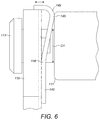
- FIG. 6 depicts a side view of an improved pin and carrier locking assembly when the arms of the washer have been bent into their final locked position
- FIG. 7 depicts a perspective view of an improved carrier on which planetary gears are positioned.
- a known planetary gear mechanism 10 is shown in FIGS. 1A and 1B .
- a planetary gear mechanism 10 may comprises a sun gear 11 , a ring gear 19 provided coaxial to the sun gear 11 and a plurality of planetary gears 12 positioned externally to the sun gear 11 and internally to the ring gear 19 so that the outer surface of the planetary gears 12 engage with both the external surface of the sun gear 11 and the internal surface of the ring gear 19 .
- Each planetary gear 12 is positioned around a pinion pin (not shown in FIGS. 1A and 1B ) which is concentric with and coaxial to the surrounding planetary gear 12 .
- a carrier 13 is also provided, having three pairs of radially extending arms 15 about its outer circumference, each of which has a bore 18 provided therein.
- the bore of each opposing arm 15 receives an axial end of one of the pinion pins.
- axial movement of the shaft of the pinion pin in and out of the bores 18 of the carrier 13 may be blocked using a circular washer 14 that is mounted on one side of the external surface of the carrier 13 , so as to be concentric with the sun gear 11 , as shown in FIGS. 1A and 1B .
- the washer 14 may be held in place relative to the carrier 13 and planetary gears 12 etc. via the use of fastening features such as holders 16 (see FIGS. 1A and 1B ) that are formed protruding axially away from the ears 15 of the carrier body which hold the planetary gears 12 .
- the washer 14 is further locked in place via the use of a slot 17 that is formed to extend axially somewhere around the outer perimeter of the carrier 13 , as shown in FIGS. 1A and 1 B.
- This slot 17 in the carrier 13 is positioned, sized and shaped so as to receive a correspondingly sized and shaped protrusion 37 of the carrier 13 , as shown in FIG. 1 .
- This type of known washer 14 therefore positions and locks all three pins and planetary gears 12 in place at once.
- the improved assemblies described herein require a smaller length of material, since the carrier is only required to radially extend further in the place where the satellite/planetary gears are fixed to the washer.
- the improved examples described herein with reference to FIGS. 2 to 7 therefore aim to provide a new type of mechanism for locking a pin having a relatively small diameter, such as a pinion pin in place within a carrier.
- the diameter of the pin may be in the region of between about 2 mm and 12 mm; however, in the examples shown in FIGS. 2 to 7 , the diameter is 4 mm.
- the only machining that may be necessary for the pins used in the improved assemblies described with reference to FIGS. 2 to 6 may be to provide a gripping surface on circumferentially opposite sides of the pin. As described below, this gripping surface may be performed by providing two parallel cuts (or indeed other similar gripping shapes) on the pin to prevent pin rotation when fixed with the washer.
- the improved assemblies described herein When the improved assemblies described herein are used in Irkuat Slat Actuators, these assemblies require less space than conventional assemblies.
- the traditional carrier and washer with associated holders, slots and protrusions may be replaced with a pin having a corresponding shape to the surface of the washer which it is in contact with (to grip the pin in place so that it does not move relative to the washer).
- the washer also may be pressed into place by bending the washer into position to have a side surface that has an L shape as shown in FIG. 5 (one section of which is perpendicular to the axis of the pin) and the other section which supports the arms of the washer.
- FIG. 2 depicts a perspective view of an improved locking assembly for a pin 110 relative to a carrier 130 .
- This pin 110 and carrier 130 may be found in a planetary gear mechanism such as that described above (or indeed any other system wherein a pin must be held in place relative to a carrier).
- the carrier 130 itself is depicted more clearly in FIG. 7 and may be generally ring shaped (so that the sun gear can be positioned internally to the carrier, and coaxially with the carrier 130 ), with a plurality of (e.g. three) circumferentially spaced planetary gear 120 holder sections 133 .
- Each planetary gear holder section 133 comprises two radially extending and axially facing arms, 134 , 135 , each of which comprises a bore 180 penetrating axially through the arm 134 , 135 , for receiving a pin 110 on which the planetary gear is coaxially and concentrically positioned in use.
- each pin 110 therefore extends perpendicularly to the direction of rotation R of the carrier 130 in use, as it rotates about the central axis, C, as shown in the figures.
- the pin 110 comprises a cylindrical shaft that extends longitudinally from a first end 113 to a second end 114 along its longitudinal axis, P.
- the second end 114 of the pin may have a stopper feature 119 that has a diameter that is larger than the diameter of the bores 180 in the carrier 130 , so that once the pin 110 is inserted into both the opposing arms 134 , 135 of the carrier, the pin 110 is prevented from moving any further once the second end 114 abuts the carrier 130 , as shown.
- other features may alternatively be used, which would prevent further axial movement of the pin 110 .
- FIG. 3 depicts a cross-sectional view of the planetary gear holder section 133 , showing the internal features of the assembly.
- a cylindrically shaped, and hollow bearing 116 is provided, that comprises a greater diameter than both axial ends 113 , 114 of the pin 110 .
- the pin 110 may be positioned between these first 134 and second 135 arms, as shown in FIGS. 2, 3 and 5 .
- the pin 110 is initially held in place within the carrier 130 via the axial ends 113 , 114 of the pin being received in the opposing bores 180 formed in the first and second arms 134 , 135 of each planetary gear holder section 133 of the carrier 130 .
- the cylindrical, hollow bearing 116 is first positioned to extend longitudinally between the radially extending arms 134 , 135 of the planetary gear holder section 133 and the first axial end 113 of the pin 110 is inserted through the bore of the first arm 134 , through the hollow center 1167 of the bearing 116 and finally through the center of the bore of the second arm 135 , along the axis P (which extends perpendicular to the center axis of rotation C).
- the blocking feature 119 at the second end 114 of the pin 110 then prevents any further axial movement in this direction and so the pin 110 and bearing 116 are therefore initially held in place between the two arms 134 , 135 of the carrier 130 in this way.
- the hollow bearing 116 is therefore provided around and coaxially with said pin 110 and, as shown in FIGS. 2, 3 and 5 , the bearing 116 is positioned so that it does not contact the first arm 134 of the carrier 130 but so that it does contact the second arm 135 of the carrier.
- the bearing 116 therefore has a greater diameter than the pin 110 around which it is positioned and extends from a first end 111 to a second end 112 .
- the second end 112 of the bearing is positioned so as to be in contact with and abut the inner surface of the second arm 135 of the carrier 130 , whereas the first end 111 of the bearing does not abut or contact the inner surface of the first arm 134 of the carrier 130 .
- a bendable washer 140 is positioned between the first end 111 of the bearing 116 and the inner surface of the first arm 134 of the carrier 130 , as shown in FIGS. 2, 3 and 5 .
- the washer 140 is depicted in FIG. 4 and may be generally U, V or Y-shaped having two arms 141 , 142 (i.e. the arms of the U, V, or Y-shape) extending away from a first section 143 of the washer 140 that makes the bottom section of the U, V, or Y-shape.
- the washer 140 may be positioned between the bearing 116 and the first arm 134 of the carrier so that the first section 143 (i.e. the bottom of the U, V or Y-shape) of the washer makes a first contact area 143 a with the first arm 134 of the carrier 130 .
- the washer 140 may be initially formed so that it is bent at a first angle X away from the surface that has the first contact area so as to extend towards and make a second contact area 116 b with the bearing.
- the washer 140 may initially be manufactured so that, from a side view, the two arms 141 , 142 of the U, V or Y-shape are bent in a direction away from the bottom section 143 of the washer 140 so that they extend in a plane that is at an angle x of approximately 15 to 30 degrees to the plane in which the bottom section 143 extends and contacts the internal surface of the first arm 134 of the carrier 130 .
- This bend is at a first point 148 as shown in FIGS. 2, 4 and 6 (which in some examples may correspond to the point at which the arms begin to extend away from section 134 ).
- the pin 110 is positioned as described above, internally of the two arms 141 , 142 of the washer 140 so that the second end 112 of the bearing 116 contacts the inner surface of the second arm 135 of the carrier, and the U-shaped washer 140 is positioned between the first end 111 of the bearing 116 and the inner surface of the first arm 134 of the carrier 130 , as shown in FIG. 5 .
- the top section of the arms 141 , 142 of the washer 140 can also then be bent at a second bend point 149 in a direction away from the first end 111 of the bearing 116 and the contact point 116 a so that the arms 141 , 142 then contact and rest against an outer circumferential surface, i.e. an external, or top portion of the first arm 134 of the carrier 130 as shown in FIGS. 2, 3 5 and 6 .
- the washer 140 will be described in greater detail.
- the U, V or Y-shaped washer 140 can be described has having a first U, V or Y-shaped face 146 and an opposing U, V, or Y-shaped face 147 , with side walls 149 extending there between, as shown in the figures.
- the first face 146 of the bottom section 143 of the U, V or Y-shaped washer 140 is in contact at point, or area 143 a with the inner surface of the first arm 134 of the carrier 130 , and due to the first bend at point 148 , the arms 141 , 142 therefore extend in the direction away from the first arm 134 of the carrier 130 and in the direction of the bearing 116 , as described above.
- the arms 141 , 142 of the washer 140 therefore contact the first end 111 of the bearing 116 at the second contact point 116 a via the second face 147 of the washer 140 , as described above and as shown in FIGS. 2, 3 and 5 .
- the washer 140 may then be bent backwards so that the arms 141 , 142 extend in a direction away from the bearing 116 and back in the direction of the first arm 134 of the carrier 130 so that the first face 146 of the arms of the washer 140 again contacts the first arm 134 of the carrier 130 at a third contact area 143 b , at the carrier's top, or outermost circumferential surface 134 b .
- the first face 146 of the washer 140 contacts the carrier 130 at two contact areas, 143 a and at 143 b , which are generally perpendicular to each other. Between these two contact areas, the washer 140 also contacts the bearing 116 at 116 a . These three contact areas 134 a , 116 a , 134 b allow the washer 140 to hold and lock the bearing in place on the pin 110 and relative to the carrier arms 134 , 135 .
- the washer 130 can be made from any material which may have a good condition for bending, such as any type of steel.
- opposing sides of the cylindrical outer surface of the pin 110 may be modified so that the outer surface of the pin at a certain, gripping section 110 a may have a corresponding size and shape to a gripping section 140 a provided on the inner surfaces of the arms 141 , 142 , of the washer 140 .
- the width of the gap G between the arms 141 , 142 of the washer 140 may also be smaller than the overall outer diameter D 1 of the pin 110 elsewhere, however, this gripping section 110 a of the pin 110 may provide a section 110 a of the pin 110 wherein the diameter D 2 is reduced enough that the arms 141 , 142 of the washer 140 may be positioned so as to contact and grip the gripping section 110 a of the pin at diametrically opposed positions, as is shown in FIGS. 2 and 5 .
- first and second gripping sections 110 a provided on diametrically opposite sides of the pin 110 that in use face the inner surfaces of the arms 141 , 142 of the washer 140 can be shaped and sized so as to reflect the shape and size of the inner surface of the arms with which they contact.
- the inner surfaces of the arms 141 , 142 are flat, such as is shown in FIG.
- the opposing sides 110 a of the pin 110 that contact the inner surfaces of the arms 141 , 142 can each have a section that is also flat so that the grip between the washer 140 and pin 110 is improved.
- the outer cylindrical surface of the pin 110 two parallel cuts may be made on diametrically opposing sides of the pin.
- U-shaped washers 140 are shown in FIGS. 2 to 7 , other, similar shaped washers may also be used, providing they have arms 141 , 142 , to grip either side of the pin 110 and providing that the pin 110 has gripping sections 110 a to contact and grip with these arms.
- the cuts in the pin may be made to reflect the angle at which the arms deflect away from each other (e.g. an angle that is perhaps 45 degrees), as opposed to the cuts in the being made parallel to each other (to reflect the fact that the arms 141 , 142 extend parallel to each other).
- the outer circumferential surface 134 c of the carrier arm 134 where the third contact area 134 b is made may also be modified to produce a gripping section at this third contact area 134 b .
- the section 134 c of the side wall of the carrier 130 that contacts the top of the arms 141 , 142 of the washer 140 can also be shaped and sized to reflect the shape and size of the first face 146 of the arms 141 , 142 that will eventually be in contact with it at the third contact point 134 b .
- this section 134 c section is flat to reflect the fact that the face 146 of the washer 140 that contacts it is also flat, however, any corresponding shape could, in theory, be used.
- the planetary gears 12 are positioned on the pins 110 , as is described with reference to FIGS. 1A and 1B , and individual U, V or Y-shaped washers are then used to individually lock into place the pins 110 relative the carrier 130 .
- the assembly does not comprise or require an intricately formed, circular washer that is positioned on an external side of the carrier.
- the improved locking mechanism shown in FIGS. 2 to 7 comprises a washer 140 (or plurality of washers 140 , wherein more than one planetary gear is used) that is positioned internally of the two sides, or arms 134 , 135 of the carrier 130 , as is shown in FIGS. 2 to 6 .
- each pin 110 is also individually locked in place via a washer 140 (as opposed to one washer 13 locking all three pins in place such as in the prior art and as shown in FIGS. 1A and 1B ).
Landscapes
- Engineering & Computer Science (AREA)
- General Engineering & Computer Science (AREA)
- Mechanical Engineering (AREA)
- Retarders (AREA)
- General Details Of Gearings (AREA)
Abstract
Description
Claims (15)
Applications Claiming Priority (3)
| Application Number | Priority Date | Filing Date | Title |
|---|---|---|---|
| EP17461569.0 | 2017-07-18 | ||
| EP17461569.0A EP3431822B1 (en) | 2017-07-18 | 2017-07-18 | Pin and carrier locking assembly |
| EP17461569 | 2017-07-18 |
Publications (2)
| Publication Number | Publication Date |
|---|---|
| US20190024695A1 US20190024695A1 (en) | 2019-01-24 |
| US11067112B2 true US11067112B2 (en) | 2021-07-20 |
Family
ID=59381230
Family Applications (1)
| Application Number | Title | Priority Date | Filing Date |
|---|---|---|---|
| US15/974,792 Active 2040-04-03 US11067112B2 (en) | 2017-07-18 | 2018-05-09 | Pin and carrier locking assembly |
Country Status (2)
| Country | Link |
|---|---|
| US (1) | US11067112B2 (en) |
| EP (1) | EP3431822B1 (en) |
Families Citing this family (3)
| Publication number | Priority date | Publication date | Assignee | Title |
|---|---|---|---|---|
| US11428310B2 (en) | 2019-06-03 | 2022-08-30 | Allison Transmission, Inc. | Stepped spindle |
| FR3104662B1 (en) * | 2019-12-12 | 2022-01-14 | Foundation Brakes France | Planetary carrier comprising at least one trunnion mounted floating in the body of the planetary carrier |
| CA3231901A1 (en) * | 2021-10-18 | 2023-04-27 | Zilong Ling | Displacement planetary carrier system and planetary transmission device thereof |
Citations (8)
| Publication number | Priority date | Publication date | Assignee | Title |
|---|---|---|---|---|
| GB820237A (en) | 1956-05-02 | 1959-09-16 | Pitner Alfred | Improvements in or relating to combined rotary and thrust bearing units |
| US3943780A (en) * | 1974-07-18 | 1976-03-16 | Hermann Klaue | Planetary gear drive with power distribution |
| US4524643A (en) | 1982-01-18 | 1985-06-25 | Mavilor Systemes S.A. | Epicyclic gear |
| US5356352A (en) | 1991-07-26 | 1994-10-18 | Jatco Corporation | Bearing arrangement for a planet pinion |
| US6817962B2 (en) | 2002-02-27 | 2004-11-16 | Aisin Seiki Kabushiki Kaisha | Planetary gear mechanism |
| US7568993B2 (en) * | 2004-02-11 | 2009-08-04 | Zf Friedrichshafen Ag | Planetary gear train |
| US9512900B2 (en) | 2015-05-08 | 2016-12-06 | E-Aam Driveline Systems Ab | Planetary gear mechanism with reduced gear lash |
| US20170227093A1 (en) * | 2016-02-09 | 2017-08-10 | Toyota Jidosha Kabushiki Kaisha | Planetary gear unit |
-
2017
- 2017-07-18 EP EP17461569.0A patent/EP3431822B1/en active Active
-
2018
- 2018-05-09 US US15/974,792 patent/US11067112B2/en active Active
Patent Citations (8)
| Publication number | Priority date | Publication date | Assignee | Title |
|---|---|---|---|---|
| GB820237A (en) | 1956-05-02 | 1959-09-16 | Pitner Alfred | Improvements in or relating to combined rotary and thrust bearing units |
| US3943780A (en) * | 1974-07-18 | 1976-03-16 | Hermann Klaue | Planetary gear drive with power distribution |
| US4524643A (en) | 1982-01-18 | 1985-06-25 | Mavilor Systemes S.A. | Epicyclic gear |
| US5356352A (en) | 1991-07-26 | 1994-10-18 | Jatco Corporation | Bearing arrangement for a planet pinion |
| US6817962B2 (en) | 2002-02-27 | 2004-11-16 | Aisin Seiki Kabushiki Kaisha | Planetary gear mechanism |
| US7568993B2 (en) * | 2004-02-11 | 2009-08-04 | Zf Friedrichshafen Ag | Planetary gear train |
| US9512900B2 (en) | 2015-05-08 | 2016-12-06 | E-Aam Driveline Systems Ab | Planetary gear mechanism with reduced gear lash |
| US20170227093A1 (en) * | 2016-02-09 | 2017-08-10 | Toyota Jidosha Kabushiki Kaisha | Planetary gear unit |
Non-Patent Citations (1)
| Title |
|---|
| European Search Report for Application No. 17461569.0-1012 dated Jan. 23, 2018, 7 pages. |
Also Published As
| Publication number | Publication date |
|---|---|
| EP3431822A1 (en) | 2019-01-23 |
| US20190024695A1 (en) | 2019-01-24 |
| EP3431822B1 (en) | 2020-09-02 |
Similar Documents
| Publication | Publication Date | Title |
|---|---|---|
| US11067112B2 (en) | Pin and carrier locking assembly | |
| EP3564055B1 (en) | Battery securing device, traction battery comprising the same and vehicle | |
| JP4330162B2 (en) | Axle assembly with bearing adjustment mechanism | |
| US8905894B2 (en) | Pinion shaft support structure for planetary gear | |
| WO2015115324A1 (en) | Reduction gear with brake | |
| US10864579B2 (en) | Chuck | |
| US5308207A (en) | Retaining ring and shaft for securing a component thereon | |
| US11441664B2 (en) | Cam device | |
| US9518648B2 (en) | Staked planet pin | |
| US9482285B2 (en) | Hybrid torque transmission mechanism | |
| JP2008038944A (en) | Manufacturing method for simple planetary gear unit, and simple planetary gear unit | |
| US20100209183A1 (en) | Mechanical locking arrangement of an axial disk | |
| US20150361835A1 (en) | Cam follower unit | |
| WO2016062357A1 (en) | Roller screw mechanism, assembly process of such a mechanism and gate valve equipped with such a mechanism | |
| EP4001694B1 (en) | Reducer | |
| EP1636502B1 (en) | Locking ring and method for connecting a device therewith | |
| US5806367A (en) | Intermittent indexing apparatus using cam mechanism | |
| WO2015031118A1 (en) | Bearing pin upset method to retain high hardness pins | |
| JP2021028524A (en) | Fixture | |
| JP2019113169A (en) | Linear motion actuator | |
| JP2020143748A (en) | Cross roller bearing | |
| JPH0227204Y2 (en) | ||
| JP2015124787A (en) | Fixing method of rolling bearing inner ring and fixing structure of rolling bearing inner ring | |
| CN120418554A (en) | Speed reducing mechanism and robot | |
| EP3680501B1 (en) | Retaining ring assemblies |
Legal Events
| Date | Code | Title | Description |
|---|---|---|---|
| FEPP | Fee payment procedure |
Free format text: ENTITY STATUS SET TO UNDISCOUNTED (ORIGINAL EVENT CODE: BIG.); ENTITY STATUS OF PATENT OWNER: LARGE ENTITY |
|
| AS | Assignment |
Owner name: HAMILTON SUNDSTRAND CORPORATION, NORTH CAROLINA Free format text: ASSIGNMENT OF ASSIGNORS INTEREST;ASSIGNOR:HS WROCLAW SP. Z O.O;REEL/FRAME:045764/0329 Effective date: 20171005 Owner name: HS WROCLAW SP. Z O.O, POLAND Free format text: ASSIGNMENT OF ASSIGNORS INTEREST;ASSIGNORS:KOCZWARA, WOJCIECH;WILK, TOMASZ;REEL/FRAME:045764/0282 Effective date: 20170809 |
|
| STPP | Information on status: patent application and granting procedure in general |
Free format text: DOCKETED NEW CASE - READY FOR EXAMINATION |
|
| STPP | Information on status: patent application and granting procedure in general |
Free format text: NOTICE OF ALLOWANCE MAILED -- APPLICATION RECEIVED IN OFFICE OF PUBLICATIONS |
|
| STPP | Information on status: patent application and granting procedure in general |
Free format text: PUBLICATIONS -- ISSUE FEE PAYMENT RECEIVED |
|
| STPP | Information on status: patent application and granting procedure in general |
Free format text: PUBLICATIONS -- ISSUE FEE PAYMENT VERIFIED |
|
| STCF | Information on status: patent grant |
Free format text: PATENTED CASE |
|
| MAFP | Maintenance fee payment |
Free format text: PAYMENT OF MAINTENANCE FEE, 4TH YEAR, LARGE ENTITY (ORIGINAL EVENT CODE: M1551); ENTITY STATUS OF PATENT OWNER: LARGE ENTITY Year of fee payment: 4 |