US11066213B2 - Container lid - Google Patents
Container lid Download PDFInfo
- Publication number
- US11066213B2 US11066213B2 US16/468,686 US201816468686A US11066213B2 US 11066213 B2 US11066213 B2 US 11066213B2 US 201816468686 A US201816468686 A US 201816468686A US 11066213 B2 US11066213 B2 US 11066213B2
- Authority
- US
- United States
- Prior art keywords
- lid
- side wall
- outer side
- container lid
- insert
- Prior art date
- Legal status (The legal status is an assumption and is not a legal conclusion. Google has not performed a legal analysis and makes no representation as to the accuracy of the status listed.)
- Active, expires
Links
Images


Classifications
-
- B—PERFORMING OPERATIONS; TRANSPORTING
- B65—CONVEYING; PACKING; STORING; HANDLING THIN OR FILAMENTARY MATERIAL
- B65D—CONTAINERS FOR STORAGE OR TRANSPORT OF ARTICLES OR MATERIALS, e.g. BAGS, BARRELS, BOTTLES, BOXES, CANS, CARTONS, CRATES, DRUMS, JARS, TANKS, HOPPERS, FORWARDING CONTAINERS; ACCESSORIES, CLOSURES, OR FITTINGS THEREFOR; PACKAGING ELEMENTS; PACKAGES
- B65D41/00—Caps, e.g. crown caps or crown seals, i.e. members having parts arranged for engagement with the external periphery of a neck or wall defining a pouring opening or discharge aperture; Protective cap-like covers for closure members, e.g. decorative covers of metal foil or paper
- B65D41/02—Caps or cap-like covers without lines of weakness, tearing strips, tags, or like opening or removal devices
- B65D41/04—Threaded or like caps or cap-like covers secured by rotation
- B65D41/0407—Threaded or like caps or cap-like covers secured by rotation with integral sealing means
- B65D41/0414—Threaded or like caps or cap-like covers secured by rotation with integral sealing means formed by a plug, collar, flange, rib or the like contacting the internal surface of a container neck
-
- B—PERFORMING OPERATIONS; TRANSPORTING
- B65—CONVEYING; PACKING; STORING; HANDLING THIN OR FILAMENTARY MATERIAL
- B65D—CONTAINERS FOR STORAGE OR TRANSPORT OF ARTICLES OR MATERIALS, e.g. BAGS, BARRELS, BOTTLES, BOXES, CANS, CARTONS, CRATES, DRUMS, JARS, TANKS, HOPPERS, FORWARDING CONTAINERS; ACCESSORIES, CLOSURES, OR FITTINGS THEREFOR; PACKAGING ELEMENTS; PACKAGES
- B65D21/00—Nestable, stackable or joinable containers; Containers of variable capacity
- B65D21/02—Containers specially shaped, or provided with fittings or attachments, to facilitate nesting, stacking, or joining together
- B65D21/0201—Containers specially shaped, or provided with fittings or attachments, to facilitate nesting, stacking, or joining together stackable or joined together side-by-side
- B65D21/0204—Containers specially shaped, or provided with fittings or attachments, to facilitate nesting, stacking, or joining together stackable or joined together side-by-side and joined together by interconnecting formations forming part of the container, e.g. dove-tail, snap connections, hook elements
-
- B—PERFORMING OPERATIONS; TRANSPORTING
- B65—CONVEYING; PACKING; STORING; HANDLING THIN OR FILAMENTARY MATERIAL
- B65D—CONTAINERS FOR STORAGE OR TRANSPORT OF ARTICLES OR MATERIALS, e.g. BAGS, BARRELS, BOTTLES, BOXES, CANS, CARTONS, CRATES, DRUMS, JARS, TANKS, HOPPERS, FORWARDING CONTAINERS; ACCESSORIES, CLOSURES, OR FITTINGS THEREFOR; PACKAGING ELEMENTS; PACKAGES
- B65D51/00—Closures not otherwise provided for
- B65D51/24—Closures not otherwise provided for combined or co-operating with auxiliary devices for non-closing purposes
-
- B—PERFORMING OPERATIONS; TRANSPORTING
- B65—CONVEYING; PACKING; STORING; HANDLING THIN OR FILAMENTARY MATERIAL
- B65D—CONTAINERS FOR STORAGE OR TRANSPORT OF ARTICLES OR MATERIALS, e.g. BAGS, BARRELS, BOTTLES, BOXES, CANS, CARTONS, CRATES, DRUMS, JARS, TANKS, HOPPERS, FORWARDING CONTAINERS; ACCESSORIES, CLOSURES, OR FITTINGS THEREFOR; PACKAGING ELEMENTS; PACKAGES
- B65D81/00—Containers, packaging elements, or packages, for contents presenting particular transport or storage problems, or adapted to be used for non-packaging purposes after removal of contents
- B65D81/36—Containers, packaging elements, or packages, for contents presenting particular transport or storage problems, or adapted to be used for non-packaging purposes after removal of contents adapted to be used for non-packaging purposes after removal of contents
- B65D81/361—Modular elements with complementary shapes, interengageable parts or the like
Definitions
- the present invention relates to a lid for sealing a filling tube connected to an external environment, and particular relates to a container lid.
- a sealed container for storing materials is usually provided with a filling tube in order to facilitate the filling and pouring of materials.
- the sealed container is a flexible package for packaging liquid foods such as juice, milk, sucking jelly and the like
- the filling tube can also be used as a drinking straw.
- a sealing lid is generally arranged at an opening of the filling tube.
- An outer wall of the filling tube is provided with a thread
- an inner wall of the sealing lid is also provided with a thread. Through a threaded connection between the sealing lid and the filling tube, the sealing lid is installed on the opening of the filling tube, thereby effectively protecting the materials in the container.
- the existing lids generally only have the function of sealing an opening of a container such as a bottle or a package. Once the materials contained in the container are used up, the container such as the bottle and the package may be recycled and reused due to a large size and a high value. However, a value of the lid is very small, so the lid is often discarded at will, and basically loses a value for secondary use, resulting in a lot of waste. Moreover, throwing the lid away randomly is prone to causing waste and damage to the environment.
- the objective of the present invention is to provide a container lid.
- the container lid can be used to seal the container filling tube.
- various container lids can be further assembled to form various shapes, thereby improving the usage and interest of the lid, and facilitating the collection of the lid.
- a container lid includes a lid for sealing a filling tube connected to an external environment.
- a bottom end of the lid is provided with a hollow inner cavity, and an inner side wall of the hollow inner cavity is provided with a thread,
- An upper end of the lid is provided with at least two sliding grooves.
- an outer side wall of the lid is provided with at least one first insertion unit and at least one second insertion unit.
- the first unit includes an insert block
- the second insertion unit includes an insert groove
- both sides of the insert block connected to the outer side wall of the lid are provided with rounded corners, and two sides of the insert groove connected to the outer side wall of the lid are provided with rounded corners.
- the rounded corners of the insert block are rounded corners of the outer side wall concaving inwards, and the rounded corners of the insert groove are rounded corners of the outer side wall protruding outwards.
- an upper end side of the insert block is provided with a protrusion.
- the bottom end of the lid is provided with at least one insert bar and at least one insert hole.
- each sliding groove has a circular arc shape, the sliding grooves are evenly disposed on the upper end of the lid, and a fixed groove is disposed between adjacent sliding grooves.
- fixed grooves are symmetrical with each other, and a length of the insert block is a half of a length of the symmetric fixed groove.
- the sliding groove has an amplitude of 20°-25°.
- the present invention can be used for sealing container filling tubes.
- the lids of the present invention can be assembled into any combined shape, thereby increasing interest, reducing garbage pollution, and promoting environmental protection.
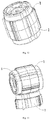
- FIG. 1 is a schematic diagram of an overall structure of the present invention.
- FIG. 2 is a schematic diagram of an overall structure of the present invention from another direction.
- FIG. 3 is a first use state reference diagram of the preferred embodiment as shown in FIG. 1 .
- FIG. 5 is a third use state reference diagram of the preferred embodiment as shown in FIG. 1 .
- FIG. 6 is a fourth use state reference diagram of the preferred embodiment as shown in FIG. 1 .
- FIG. 7 is a fifth use state reference diagram of the preferred embodiment as shown in FIG. 1 .
- FIG. 8 is a sixth use state reference diagram of the preferred embodiment as shown in FIG. 1 .
- FIG. 9 is a top view of the sixth use state reference diagram of the preferred embodiment as shown in FIG. 1 .
- FIG. 10 is a seventh use state reference diagram of the preferred embodiment as shown in FIG. 1 .
- FIG. 11 is an eighth use state reference diagram of the preferred embodiment as shown in FIG. 1 .
- FIG. 12 is a ninth use state reference diagram of the preferred embodiment as shown in FIG. 1 .
- FIG. 13 is a tenth use state reference diagram of the preferred embodiment as shown in FIG. 1 .
- a container lid is disclosed in the present embodiment.
- the container lid includes the lid 1 for sealing a filling tube connected to an external environment.
- a bottom end of the lid 1 is provided with the hollow inner cavity 2
- the thread 21 is provided on an inner side wall of the hollow inner cavity 2 .
- An upper end of the lid 1 is evenly provided with six sliding grooves 13 .
- Each sliding groove has a circular arc shape, and a rotation amplitude ⁇ of each sliding groove is 20° to 25°.
- the fixed groove 14 for fixing is disposed between the two adjacent sliding grooves 13 . and the fixing grooves 14 are symmetrical to each other.
- An outer side wall of the lid 1 is provided with three first insertion units and three second insertion units.
- Each first insertion unit includes the insert block 11
- each second insertion unit includes the insert groove 12 .
- the insert blocks 11 and the insert grooves 12 are evenly provided on the outer side wall of the lid 1 in a staggered manner.
- An upper end of the insert block 11 is provided with a protrusion, and a length of the insert block 11 is a half of a length of the symmetric fixing groove 14 .
- Two sides of the insertion block 11 connected to the outer side wall of the lid 1 are provided with rounded corners, and two sides of the insert groove 12 connected to the outer side wall of the lid 1 are also provided with rounded corners.
- the rounded corners of the insert block 11 are rounded corners of the outer side wall concaving inwards, and the rounded corners of the insert groove 12 are rounded corners of the outer side wall protruding outwards.
- the reinforcing ribs 22 are uniformly disposed between an outer side wall of the inner cavity 2 and an inner side wall of the lid 1 ,
- the reinforcing ribs 22 are respectively provided with six of the insert bars 23 and six of the insert holes 24 , and the insert bars 23 and the insert holes 24 are disposed on the reinforcing ribs 22 in a staggered manner.
- the present invention further includes the following embodiments.
- the insertion block 11 of the first lid 1 is inserted into the insert groove 12 of the second lid 1 , so that the first lid 1 is connected to the second lid 1 .
- Two sides of the insert block 11 connected to the outer side wall of the first lid 1 and two sides of the insert groove 12 connected to the outer side wall of the second lid 1 are respectively provided with rounded corners, thereby the first lid 1 and the second lid 1 can rotate along the rounded corners by a predetermined angle.
- the two lids 1 may be connected to each other in a same direction or a reverse direction as needed, and an unlimited number of lids may be connected according to actual demand.
- the insert bar 23 of the first lid 1 is inserted into the sliding groove 13 of the second lid 1 , and the insert bar 23 of the first lid 1 may slide along an arc in the sliding groove 13 .
- the insert bar 23 of the first lid 1 is inserted into the insert hole 24 of the second lid 1 , thereby the first lid 1 is connected to the second lid 2 .
- the protrusions at both ends of the insert blocks 11 of the two lids are used for fixing in the fixed groove 14 at an upper end of the third lid 1 .
- the present invention can be used for sealing container filling tubes.
- the lids of the present invention can be assembled to form any combined shapes, thereby reducing garbage pollution and promoting environmental protection.
Abstract
Description
Claims (17)
Applications Claiming Priority (3)
| Application Number | Priority Date | Filing Date | Title |
|---|---|---|---|
| CN201810973938.X | 2018-08-24 | ||
| CN201810973938.XA CN108861026A (en) | 2018-08-24 | 2018-08-24 | A kind of container cover |
| PCT/CN2018/109024 WO2020037788A1 (en) | 2018-08-24 | 2018-09-30 | Container lid |
Publications (2)
| Publication Number | Publication Date |
|---|---|
| US20210002033A1 US20210002033A1 (en) | 2021-01-07 |
| US11066213B2 true US11066213B2 (en) | 2021-07-20 |
Family
ID=64321827
Family Applications (1)
| Application Number | Title | Priority Date | Filing Date |
|---|---|---|---|
| US16/468,686 Active 2039-02-26 US11066213B2 (en) | 2018-08-24 | 2018-09-30 | Container lid |
Country Status (3)
| Country | Link |
|---|---|
| US (1) | US11066213B2 (en) |
| CN (1) | CN108861026A (en) |
| WO (1) | WO2020037788A1 (en) |
Families Citing this family (8)
| Publication number | Priority date | Publication date | Assignee | Title |
|---|---|---|---|---|
| USD971730S1 (en) | 2020-10-29 | 2022-12-06 | Cheer Pack North America | Cap for a pouch |
| USD966890S1 (en) | 2020-10-29 | 2022-10-18 | Cheer Pack North America | Cap for a pouch |
| USD962766S1 (en) | 2020-10-29 | 2022-09-06 | Cheer Pack North America | Cap for a pouch |
| USD971728S1 (en) | 2020-10-29 | 2022-12-06 | Cheer Pack North America | Cap for a pouch |
| US11414244B2 (en) * | 2020-10-29 | 2022-08-16 | Cheer Pack North America | System and method for connecting members |
| USD962764S1 (en) | 2020-10-29 | 2022-09-06 | Cheer Pack North America | Cap for a pouch |
| USD962765S1 (en) | 2020-10-29 | 2022-09-06 | Cheer Pack North America | Cap for a pouch |
| CN115477099A (en) * | 2021-06-15 | 2022-12-16 | 元礼国际贸易股份有限公司 | Container adapter |
Citations (5)
| Publication number | Priority date | Publication date | Assignee | Title |
|---|---|---|---|---|
| WO2001068210A2 (en) | 2000-03-15 | 2001-09-20 | Alottafun!, Inc. | Toy capsule |
| CN202346087U (en) | 2011-09-08 | 2012-07-25 | 汕头市虹桥包装实业有限公司 | Magic cover |
| CN205087350U (en) | 2015-09-06 | 2016-03-16 | 罗仕泽 | Can splice container lid with axial splicing mechanism |
| CN205366461U (en) | 2015-12-11 | 2016-07-06 | 厦门德冠科技有限公司 | Combined cap |
| CN207292902U (en) | 2017-09-30 | 2018-05-01 | 福建亲亲股份有限公司 | A kind of food containers, container cover and building blocks lid |
Family Cites Families (3)
| Publication number | Priority date | Publication date | Assignee | Title |
|---|---|---|---|---|
| CN205257021U (en) * | 2015-09-06 | 2016-05-25 | 罗仕泽 | Container lid with side concatenation unit |
| CN207141798U (en) * | 2017-08-18 | 2018-03-27 | 林振宇 | A kind of combination cover of packaging bag |
| CN208647535U (en) * | 2018-08-24 | 2019-03-26 | 厦门德冠科技有限公司 | A kind of container cover |
-
2018
- 2018-08-24 CN CN201810973938.XA patent/CN108861026A/en active Pending
- 2018-09-30 US US16/468,686 patent/US11066213B2/en active Active
- 2018-09-30 WO PCT/CN2018/109024 patent/WO2020037788A1/en active Application Filing
Patent Citations (5)
| Publication number | Priority date | Publication date | Assignee | Title |
|---|---|---|---|---|
| WO2001068210A2 (en) | 2000-03-15 | 2001-09-20 | Alottafun!, Inc. | Toy capsule |
| CN202346087U (en) | 2011-09-08 | 2012-07-25 | 汕头市虹桥包装实业有限公司 | Magic cover |
| CN205087350U (en) | 2015-09-06 | 2016-03-16 | 罗仕泽 | Can splice container lid with axial splicing mechanism |
| CN205366461U (en) | 2015-12-11 | 2016-07-06 | 厦门德冠科技有限公司 | Combined cap |
| CN207292902U (en) | 2017-09-30 | 2018-05-01 | 福建亲亲股份有限公司 | A kind of food containers, container cover and building blocks lid |
Also Published As
| Publication number | Publication date |
|---|---|
| US20210002033A1 (en) | 2021-01-07 |
| WO2020037788A1 (en) | 2020-02-27 |
| CN108861026A (en) | 2018-11-23 |
Similar Documents
| Publication | Publication Date | Title |
|---|---|---|
| US11066213B2 (en) | Container lid | |
| RU2706834C2 (en) | Cover for containers | |
| US20150129536A1 (en) | Lightweight, vacuum-resistant containers having offset horizontal ribs | |
| BR112015020233B1 (en) | POWDER PACKAGING FOR CHILDREN'S FORMULA; AND PLURALITY OF NARROW PROFILE SHELLS FOR DOSAGE OF CHILDREN'S FORMULA POWDER | |
| US9434499B2 (en) | Containers having improved vacuum resistance | |
| US20110290756A1 (en) | Threaded cap | |
| BRPI1106785A2 (en) | Hot-Potted Plastic Container | |
| JP2010036942A (en) | Plastic bottle | |
| US20110226721A1 (en) | Threaded closure assembly | |
| WO2014179849A1 (en) | Improvement to packaging for beverages and the like | |
| JP2014156272A (en) | Plastic bottle | |
| BR112015001204B1 (en) | CONTAINER FOR LIQUIDS | |
| CN205060331U (en) | Fluoridize antiseep and annotate bottle blowing | |
| CN219928614U (en) | Bucket with leak protection, sealing function | |
| JPWO2015194040A1 (en) | Resin cap | |
| EP3088317B1 (en) | Bottle container | |
| CN207998062U (en) | A kind of Packaging Bottle | |
| EP2103532A1 (en) | Bottle crate | |
| CN204979656U (en) | Seasoning bottle lid | |
| CN210102531U (en) | Cold drink holding box | |
| CN204193983U (en) | A kind of blood sample rack for test tube | |
| AR110898A2 (en) | PROCESS AND EQUIPMENT FOR THE MANUFACTURE OF GLASS CONTAINERS WITH THREADED NECK INSIDE | |
| GB2503192A (en) | Container for Nestling Between Bottles in a Crate | |
| US20210155361A1 (en) | Container for receiving liquids | |
| SE525998C2 (en) | Parallelopiped package for drink is provided with mouth from which drinking can be carried out, mouth being closable by closure part |
Legal Events
| Date | Code | Title | Description |
|---|---|---|---|
| AS | Assignment |
Owner name: XIAMEN DEGUAN TECHNOLOGY CO., LTD., CHINA Free format text: ASSIGNMENT OF ASSIGNORS INTEREST;ASSIGNOR:LIN, MANFAN;REEL/FRAME:049454/0286 Effective date: 20190516 |
|
| FEPP | Fee payment procedure |
Free format text: ENTITY STATUS SET TO UNDISCOUNTED (ORIGINAL EVENT CODE: BIG.); ENTITY STATUS OF PATENT OWNER: SMALL ENTITY |
|
| FEPP | Fee payment procedure |
Free format text: ENTITY STATUS SET TO SMALL (ORIGINAL EVENT CODE: SMAL); ENTITY STATUS OF PATENT OWNER: SMALL ENTITY |
|
| STPP | Information on status: patent application and granting procedure in general |
Free format text: NON FINAL ACTION MAILED |
|
| STPP | Information on status: patent application and granting procedure in general |
Free format text: RESPONSE TO NON-FINAL OFFICE ACTION ENTERED AND FORWARDED TO EXAMINER |
|
| STPP | Information on status: patent application and granting procedure in general |
Free format text: NOTICE OF ALLOWANCE MAILED -- APPLICATION RECEIVED IN OFFICE OF PUBLICATIONS |
|
| STPP | Information on status: patent application and granting procedure in general |
Free format text: PUBLICATIONS -- ISSUE FEE PAYMENT RECEIVED |
|
| STPP | Information on status: patent application and granting procedure in general |
Free format text: PUBLICATIONS -- ISSUE FEE PAYMENT VERIFIED |
|
| STCF | Information on status: patent grant |
Free format text: PATENTED CASE |