US11064045B2 - Method and system for processing service function chain request - Google Patents
Method and system for processing service function chain request Download PDFInfo
- Publication number
- US11064045B2 US11064045B2 US16/672,050 US201916672050A US11064045B2 US 11064045 B2 US11064045 B2 US 11064045B2 US 201916672050 A US201916672050 A US 201916672050A US 11064045 B2 US11064045 B2 US 11064045B2
- Authority
- US
- United States
- Prior art keywords
- vnf
- server
- service function
- function chain
- domain
- Prior art date
- Legal status (The legal status is an assumption and is not a legal conclusion. Google has not performed a legal analysis and makes no representation as to the accuracy of the status listed.)
- Active, expires
Links
Images


Classifications
-
- H04L67/32—
-
- H—ELECTRICITY
- H04—ELECTRIC COMMUNICATION TECHNIQUE
- H04J—MULTIPLEX COMMUNICATION
- H04J14/00—Optical multiplex systems
- H04J14/02—Wavelength-division multiplex systems
- H04J14/0227—Operation, administration, maintenance or provisioning [OAMP] of WDM networks, e.g. media access, routing or wavelength allocation
- H04J14/0254—Optical medium access
- H04J14/0267—Optical signaling or routing
-
- H—ELECTRICITY
- H04—ELECTRIC COMMUNICATION TECHNIQUE
- H04J—MULTIPLEX COMMUNICATION
- H04J14/00—Optical multiplex systems
- H04J14/02—Wavelength-division multiplex systems
- H04J14/0201—Add-and-drop multiplexing
- H04J14/0202—Arrangements therefor
- H04J14/021—Reconfigurable arrangements, e.g. reconfigurable optical add/drop multiplexers [ROADM] or tunable optical add/drop multiplexers [TOADM]
- H04J14/0212—Reconfigurable arrangements, e.g. reconfigurable optical add/drop multiplexers [ROADM] or tunable optical add/drop multiplexers [TOADM] using optical switches or wavelength selective switches [WSS]
-
- H—ELECTRICITY
- H04—ELECTRIC COMMUNICATION TECHNIQUE
- H04L—TRANSMISSION OF DIGITAL INFORMATION, e.g. TELEGRAPHIC COMMUNICATION
- H04L12/00—Data switching networks
- H04L12/28—Data switching networks characterised by path configuration, e.g. LAN [Local Area Networks] or WAN [Wide Area Networks]
- H04L12/46—Interconnection of networks
- H04L12/4641—Virtual LANs, VLANs, e.g. virtual private networks [VPN]
-
- H—ELECTRICITY
- H04—ELECTRIC COMMUNICATION TECHNIQUE
- H04L—TRANSMISSION OF DIGITAL INFORMATION, e.g. TELEGRAPHIC COMMUNICATION
- H04L41/00—Arrangements for maintenance, administration or management of data switching networks, e.g. of packet switching networks
- H04L41/50—Network service management, e.g. ensuring proper service fulfilment according to agreements
- H04L41/5003—Managing SLA; Interaction between SLA and QoS
-
- H—ELECTRICITY
- H04—ELECTRIC COMMUNICATION TECHNIQUE
- H04L—TRANSMISSION OF DIGITAL INFORMATION, e.g. TELEGRAPHIC COMMUNICATION
- H04L43/00—Arrangements for monitoring or testing data switching networks
- H04L43/08—Monitoring or testing based on specific metrics, e.g. QoS, energy consumption or environmental parameters
- H04L43/0852—Delays
-
- H—ELECTRICITY
- H04—ELECTRIC COMMUNICATION TECHNIQUE
- H04L—TRANSMISSION OF DIGITAL INFORMATION, e.g. TELEGRAPHIC COMMUNICATION
- H04L67/00—Network arrangements or protocols for supporting network services or applications
- H04L67/01—Protocols
- H04L67/10—Protocols in which an application is distributed across nodes in the network
-
- H—ELECTRICITY
- H04—ELECTRIC COMMUNICATION TECHNIQUE
- H04L—TRANSMISSION OF DIGITAL INFORMATION, e.g. TELEGRAPHIC COMMUNICATION
- H04L67/00—Network arrangements or protocols for supporting network services or applications
- H04L67/50—Network services
- H04L67/60—Scheduling or organising the servicing of application requests, e.g. requests for application data transmissions using the analysis and optimisation of the required network resources
Definitions
- the disclosure relates to communication technology, in particular to a method and a system for processing a service function chain request.
- a service function chain may comprise a plurality of network functions. For example, if a user's request goes through a firewall (FW), an intrusion detection system (IDS), and a network address translator (NAT), the service function chain may contain an FW, an IDS, and an NAT.
- FW firewall
- IDS intrusion detection system
- NAT network address translator
- network functions are usually deployed in specific physical devices. In this way of deployment, the costs for purchasing, maintaining and upgrading physical devices would be very high. Further, due to the fact that physical devices are usually operated and managed with specific programming languages, the labor cost of the personnel with specific skills to maintain the physical devices would also be very high. In addition, as the scale of the network continues to expand, the number of devices in the existing network and the performance of these devices can no longer meet the needs of emerging applications. Moreover, physical devices are typically deployed at particular nodes in the network. Therefore, the locations of these physical devices may become conditions which should be taken into account when performing path computations for traffic flows that require network functions deployed in these physical devices. Thus, the processing latency of a service function chain would be increased and unnecessary waste on resources would occur.
- VNF Virtual Network Function
- NFV Network Function Virtualization
- optical interconnecting technology is not suitable for services that need frequent connects/disconnects, such as low-rate but high-burst services.
- data processing rates of VNFs are different, using a VNF with a high data processing rate to process services with small data volume may occupy more computing resources and storage resources than those needed.
- competition on resources with services with high data throughput requirements would occur, which results in a degradation on the performance of the network.
- Examples of the disclosure provide a method for processing a service function chain request.
- the method may include:
- classifying a service function chain request received wherein the service function chain requested by the service function chain request comprises at least one virtual network function VNF;
- the domain may include one of an optical domain or an electrical domain
- classifying the service function chain request received may include: classifying the service function chain request according to at least one of the rate of the service function chain request or a parameter of Service Level Agreement.
- determining at least one server for implementing the at least one VNF may include:
- each row of the calculation matrix corresponds to each available server in the domain, each column corresponds to each of the at least on VNF, and each element indicates whether the corresponding server contains the corresponding VNF instance;
- selecting at least one server from the available servers to implement the at least one VNF may include:
- the length of the comparison vector is
- the bit-by-bit shift operation may include a bit-by-bit right shift operation, and j-bit zero sequence is padded at the first j bits of each row.
- the length of the comparison vector is
- the bit-by-bit shift operation includes a bit-by-bit left shift operation and a j-bit zero sequence is padded at the last j bits of each row.
- selecting at least one server from the available servers to implement the at least one VNF may include: converting each row of the calculation matrix into a decimal value to obtain a vector V;
- performing an AND operation on each row of the calculation matrix and a comparison vector may include: performing an AND operation on each element of the vector V and 2 j ⁇ 1;
- determining whether the result of the AND operation is equal to the comparison vector or not may include: determining whether the result of the AND operation is equal to 2 j ⁇ 1 or not;
- carrying out a bit-by-bit shift operation on each row of the calculation matrix and performing a zero padding on each row of the calculation matrix may include: shifting each element in the vector V to the right by j bits and padding j bits of zeros at the first j bits.
- determining whether a VNF instance sequence is available may include:
- selecting a server with sufficient capacity to create all required VNF instances may include: selecting a server with sufficient capacity and minimal remaining capacity to create all required VNF instances.
- determining the time at which the at least one server implements the at least one VNF may include:
- the method may further include:
- checking whether the requested frequency of each VNF matches the distribution of each VNF in the system may include:
- T represents the set of instances of all VNFs in the system
- C Fn represents the number of times VNF instance F n is requested
- I Fn represents the number of VNF instances F n in the current system
- deploying the VNF instance in a server may include: selecting a server that contains the least VNF instances and deploying the VNF instance in the server selected.
- the method may further include:
- VNF instance after a certain VNF instance processes the service function chain request, setting the VNF instance to be in an idle state; wherein the maintenance time of the idle state is set as the keep-alive time corresponding to the VNF instance;
- the method may further include:
- Examples of the disclosure provide a system for processing a service function chain request.
- the system may include:
- a request discriminator to classify a service function chain request received and determine a domain to process the service function chain request; wherein the service function chain requested by the service function chain request may include at least one VNF; the domain may include one of an optical domain or an electrical domain;
- ROADM reconfigurable optical add-drop multiplexer
- a software definition network controller to control the request discriminator and set classification rules of the request discriminator; and configure the ROADM;
- optical domain data center connected to the ROADM, wherein the optical domain data center comprises at least one VNF;
- an electrical domain data center connected to the ROADM, wherein the electrical domain data center comprises at least one VNF;
- a network function virtualization controller to monitor and maintain the operation state of the at least one VNF in the optical domain data center and the electric domain data center and adjust the deployment of the at least one VNF.
- the optical domain data center may include:
- WSS wavelength selective switch
- At least one optical domain server connected to the at least one WSS; wherein, the at least one optical domain server includes at least one VNF; the at least one WSS is used for performing wavelength exchange between the at least one optical domain server and the ROADM.
- the electric domain data center may include:
- a switch for connecting the at least one electric domain server and the ROADM; wherein the at least one electric domain server includes at least one VNF.
- system may further include:
- an Operation Support System/Business Support System OSS/BSS configured to perform policy distribution and parameter setting on the network function virtualization controller and the software definition network controller through an API and the coordination controller.
- a high-speed service function chain request can be distributed to the VNFs in the optical domain with a higher throughput for processing, and a high-burstiness and low-speed service can be distributed to the VNFs in the electrical domain for processing.
- the network state can be monitored and recorded in real time, and then the deployment of the VNFs can be adjusted accordingly, the requirements of the services can be flexibly met, and the waste on bandwidth resources or storage resources caused by the changes of the services can be reduced.
- the method and system for processing a service function chain request performs a differentiated processing on different service function chain requests through service discrimination, which improves the utilization efficiency of the computing resources and the bandwidth resources in data centers, reduces the network congestion rate and improves the performance of the network.
- the deployment of the VNFs in the data centers can be adjusted in time so as to adapt the system to different applications, thereby the adaptability and self-adjustment capability of the network would be achieved.
- FIG. 1 is a diagram illustrating the structure of a system for processing a service function chain request provided by examples of the disclosure.
- FIG. 2 is a diagram illustrating the structure of an optical domain data center in accordance with one example of the disclosure.
- FIG. 3 is a flowchart illustrating a method for processing a service function chain request according to an example of the disclosure.
- FIG. 4 shows an example of a service function chain request.
- FIG. 5 is a flowchart illustrating a server mapping method according to an example of the disclosure.
- FIG. 6 is a flowchart illustrating a method for selecting at least one server from available servers to implement all VNFs in a service function chain according to a calculation matrix in accordance with an example of the disclosure.
- FIG. 7 is a flowchart illustrating a method for selecting at least one server among available servers to implement all VNFs in a service function chain according to a calculation matrix according to another example of the disclosure.
- FIG. 8 is a flowchart illustrating a method for adjusting the deployment of VNFs in a data center in accordance with one example of the disclosure.
- FIG. 9 is a flowchart illustrating a method for adjusting the deployment of VNFs in a data center in accordance with another example of the disclosure.
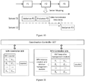
- FIG. 10 is a flowchart illustrating a time planning process for implementing VNF instances of a service function chain request in accordance with an example of the disclosure.
- FIG. 11 shows modules used by a software defined network (SDN) 103 and an NFV controller 106 to detect the state of the user and adjust VNF deployment dynamically.
- SDN software defined network
- an example of the disclosure provides a system for processing a service function chain request, the structure of which is shown in FIG. 1 and according to FIG. 1 , the system includes the following modules: a request discriminator 101 , a reconfigurable optical add-drop multiplexer (ROADM) 102 , an SDN controller 103 , an optical domain data center 104 , an electrical domain data center 105 and an NFV controller 106 .
- ROADM reconfigurable optical add-drop multiplexer
- the request discriminator 101 is configured to classify a service function chain request which is received from an external network and determine a domain to process the service function chain request.
- the domain may be an optical domain or an electrical domain.
- the request discriminator 101 may be located at a network portal throughout the data center.
- the ROADM 102 is configured to distribute the service function chain request to the domain determined.
- the ROADM 102 may distribute the service function chain request determined to be processed in the optical domain to the optical domain data center and distributed the service function chain request determined to be processed in the electrical domain to the electrical domain data center according to the classification result of the request discriminator 101 .
- the SDN controller 103 is configured to control the request discriminator 101 , set classification rules of the request discriminator 101 ; and configure the ROADM 102 to implement the distributing of the service function chain request between the optical domain and the electrical domain.
- the SDN controller 103 may reconfigure the ROADM 102 according to the classification result of the request discriminator 101 . For example, for small-grained services, the ROADM 102 may directly drop the service to the electrical domain data center for processing. And for services that need to be processed in the optical domain, the ROADM 102 may route the service to the optical domain data center for processing.
- the request discriminator 101 may determine whether the current service function chain request needs to be processed in the optical domain or in the electrical domain based on the rate of the service function chain request or at least one parameter of Service Level Agreement (SLA), such as the delay parameter. For example, the request discriminator 101 may determine that a high-speed service function chain request should be handled by high-throughput VNFs in the optical domain, while a low-speed but high-burst service function chain request should be processed by VNFs in the electrical domain.
- SLA Service Level Agreement
- the optical domain data center 104 connected to the ROADM may include at least one VNF; wherein, each of the at least one VNF is used for implementing a virtual network function in the optical domain.
- the electrical domain data center 105 connected to the ROADM may include at least one VNF; wherein, each of the at least one VNF is used for implementing a virtual network function in the electrical domain.
- the NFV controller 106 is configured to monitor and maintain the operation states of the VNFs of the optical domain data center 104 and the electric domain data center 105 and adjust the deployment of the VNFs to adapt to the requirements of services flexibly and thus to reduce the waste of bandwidth or storage resources caused by changes of the services.
- the SDN controller 103 may further monitor and record the state of the service function chain request and the state of the network and exchange necessary information with the NFV controller 106 to assist the NFV controller 106 in adjusting the deployment of the VNFs.
- both the NFV controller 106 and the SDN controller 103 can communicate with a coordination controller 107 via an upper layer interface (also referred to as a north interface).
- the coordination controller 107 may support an Operation Support System/Business Support System (OSS/BSS) 108 through an Application Programming Interface (API).
- OSS/BSS Operation Support System/Business Support System
- API Application Programming Interface
- the OSS/BSS 108 may perform policy distributions such as classification rules distributions, parameter setting, etc. through the API and the coordination controller 107 .
- the system for processing a service function chain request shown in FIG. 1 is actually a data center with efficient service function chain request processing capability based on network function virtualization.
- the data center is divided into an electric domain data center responsible for processing services with smaller granularity and an optical domain data center responsible for processing services with larger granularity.
- the electric domain data center and the optical domain data center are cooperatively managed by the SDN controller 103 and the NFV controller 106 . Specifically, operations related to VNF creation, deletion, maintenance, and etc. are performed by the NFV controller 106 ; and operations related to traffic monitoring, network element configuration, and etc. are performed by the SDN controller 103 .
- the SDN controller 103 and the NFV controller 106 may exchange necessary information in messaging, such as user requests and the state of the network monitored by the SDN controller 103 , the running state of the VNFs maintained by the NFV controller 106 , and the like.
- a service function chain request entering the data center may first be classified by the request discriminator 101 to determine a domain to process the service function chain request. That is, whether the service function chain request should be processed by the electrical domain data center or the optical domain data center.
- the request discriminator 101 may be configured and managed by the SDN controller 103 .
- the SDN controller 103 may distribute different classification rules to the request discriminator 101 .
- the SDN controller 103 may configure the ROADM 102 based on the classification result. For example, for services with smaller granularity, the ROADM 102 may directly drop the service to the electrical domain data center.
- VNFs in the electrical domain are typically small in volume and have limited processing rate, but for services with smaller granularity, the processing flexibility is high and the configuration time is short.
- the ROADM 102 may directly route the service to the optical domain data center according to the wavelength information of the service.
- deployment of the VNFs in the electrical domain, deployment of the VNFs in the optical domain, state monitoring and dynamic adjustment can all be accomplished by the NFV controller 106 .
- the NFV controller 106 can perform policy distribution on VNFs in the electrical domain data center and the optical domain data center.
- the optical domain data center 104 may include: at least one WSS and at least one optical domain server connected to each other; the at least one optical domain server includes at least one VNF; the at least one WSS is used for wavelength exchange between the at least one optical domain server and the ROADM 102 .
- the electric domain data center 105 may include: at least one electrical domain server and a switch for connecting the at least one electrical domain server and the ROADM 102 .
- the at least one electric domain server may include at least one VNF.
- the electric domain servers may also be connected to each other via a switch.
- FIG. 2 shows the structure of the optical domain data center according to an example of the disclosure.
- the optical domain data center includes three WSSs: WSS_1, WSS_2, WSS_3, and three racks (i.e., optical domain servers).
- WSS_1, WSS_2, WSS_3, and three racks i.e., optical domain servers.
- the three WSSs are connected to the three racks.
- the configuration of the WSSs by the SDN controller 103 enables wavelength exchanges between any racks.
- the WSS may be a 1*N structure, and by configuration, any wavelength output from a certain port may be realized.
- port N of WSS_3 is used to send data back to the ROADM.
- FIG. 1 the WSS_1, WSS_2, WSS_3, and three racks (i.e., optical domain servers).
- the three WSSs are connected to the three racks.
- the configuration of the WSSs by the SDN controller 103 enables wavelength exchanges between any racks.
- each rack has a transmitter TX that can modulate the data processed by the VNF onto a certain wavelength and then transmit.
- TX transparent transmission of services
- each rack has a transmitter TX that can modulate the data processed by the VNF onto a certain wavelength and then transmit.
- a high-speed service function chain request can be distributed to the VNFs with a higher routing throughput in the optical domain for processing, and a high-burst and low-speed service can be distributed to the electrical domain for processing.
- services carried by different wavelengths may be transmitted to a VNF server required by the WSS for high-speed processing.
- the NFV controller 106 the state of the network can be monitored and recorded in real time, the deployment of the VNFs can be adjusted accordingly, the requirements of the services can be flexibly met, and the waste on bandwidth resources or storage resources caused by the changes of the services can be reduced.
- the system for processing a service function chain request performs a differentiated processing on different service function chain requests through service discrimination, which improves the utilization efficiency of computing resources and network bandwidth resources in a data center optical network, reduces the network congestion rate and improves the network performance.
- the deployment of the VNFs in the data center can be adjusted in time so as to adapt to different applications with different types, or various distributions, thereby adaptability and self-adjustment capability of the network can be achieved.
- examples of the disclosure also provide a method for processing a service function chain request.
- the procedure of the method for processing a service function chain request is shown in FIG. 3 , which includes the following steps:
- step 302 a service function chain request received is classified, and a domain to process the service function chain request is determined.
- the domain may be an optical domain or an electrical domain. That is, in this step, whether the service function chain request is to be processed in the optical domain or the electrical domain is determined.
- a service function chain requested by the service function chain request may include at least one VNF.
- the above step may be performed by the request discriminator 101 under the control of the SDN controller 103 .
- the service function chain request can be determined to be processed in the optical domain; while in the case of small data packets, for the delay requirement is relatively high, the service function chain request may be determined to be processed in the electric domain in which that the processing may be relatively fast.
- the SLA contains many parameters, and the time delay is one of the parameters, so that the classification rule can be set according to one or more parameters in the SLA, to ensure the classification to be more accurate.
- the service function chain request may then be distributed to the domain determined in step 304 .
- the service function chain request would then be transmitted to the optical domain data center. And if the service function chain request is determined to be processed in the electrical domain, the service function chain request would then be transmitted to the electrical domain data center.
- step 306 a server mapping on the service function chain request allocated to the electric domain or the optical domain is performed, and thus at least one server implementing the at least one VNF included in the service function chain requested by the service function chain request is then determined.
- each server determined to implement the network function requested by the service function chain will be a server in the electric domain; and after the server mapping on the service function chain request distributed to the optical domain is carried out, each server determined for implementing the network function requested by the service function chain will be a server in the optical domain.
- the service function chain Sr denotes a set of network functions arranged in a specific order. That is, a service function chain request needs to be processed sequentially through each network function in the chain.
- FIG. 4 shows an example of a service function chain request.
- the data transmission rate parameter requested by the service function chain is br Gbps
- the requested service function chain includes three network functions, such as FW, IDS, and NAT. That is, the service function chain request needs to be processed sequentially through the FW, IDS, and NAT described above.
- the processing delay L F caused by each VNF processes the user requests may be considered to be substantially fixed, however, the transmission delay L T may vary widely from VNF to VNF.
- the transmission delays of these two VNFs may be substantially negligible.
- the transmission delay of the two VNFs may be large.
- the object of the server mapping in this step can be converted into that for a certain service function chain request, to determine at least one server which implements the network function requested by the service function chain with a smallest total transmission delay of the service function chain request. That is, the number of times that the service function chain request is transmitted among a plurality of servers should be as small as possible to avoid excessive transmission delays due to frequent transfers between servers.
- the NFV controller 106 can control the wavelength exchange of each WSS of the optical domain data center to configure of the transmission path requested by the service function chain to be processed in the optical domain; or the NFV controller 106 can control each electric domain server of the electric domain data center to configure the transmission path requested by the service function chain to be processed in the electric domain.
- step 308 a time planning on the at least one server is performed, thus the time at which the at least one server processes the at least one VNF is determined.
- the processing delay of each of the at least one VNF is determined according to the size of the data to be processed and the data processing rate of the VNF.
- the data transmission delay between each two VNF servers is determined according to the length of a pre-configured transmission path and the exchange rate of devices.
- the moment when the at least one server processes the at least one VNF is determined according to the processing delay and the transmission delay.
- the NFV controller may estimate the processing delay for each VNF instance based on the amount of user data to be processed and the data processing rate of the VNF instance. Meanwhile, the data transmission delay between the optical domain servers where two VNFs are located is estimated according to the length of the configured transmission path, the exchange rate of devices and the like. And on this basis, the moment when the VNF instance on each optical domain server starts processing the service function chain request may be preset.
- a following VNF instance should first wait for a preceding VNF instance to process the user data, and then wait for the user data to be transferred from the server where the preceding VNF instance is located to the server where the following VNF instance is located.
- the NFV controller may perform a VNF time planning in a manner similar to that described above in the optical domain. The difference is that the estimation of the data transmission delay of the electrical domain should be based on the processing rate of the electrical domain device, e.g. the switching rate of a switch, the packet forwarding rate of a router, etc.
- the NFV controller 106 can configure the determined time and the VNF to be executed corresponding to the time to the at least one server, and then each server executes the corresponding VNF according to the configured time, thereby the processing of the service function chain request can be implemented effectively.
- the method for processing a service function chain request may have the following advantages.
- different service function chain requests can be processed differently through service classification, thus the utilization efficiency of computing resources and network bandwidth resources in the data centers can be improved.
- the network congestion rate can be reduced, the network performance can be improved, and the processing delay of the service function chain requests can be reduced through VNF mapping and time planning.
- FIG. 5 shows a flowchart of the server mapping method according to examples of the disclosure. As shown in FIG. 5 , the method may include:
- VNF instances in an idle state on each server may be acquired to obtain an idle instance set corresponding to the service function chain request r.
- the VNF instance described above refers to a specific instance in which the VNF is installed, i.e., a program unit that processes user data.
- VNF instances in an idle state may be a collection.
- the idle instances set thereof may be denoted as ⁇ Q F1 , QF 2 , Q Fn >.
- a calculation matrix M is constructed according to the idle instances set, wherein each row of the calculation matrix M corresponds to each available server ⁇ E1, E2, . . . , Em>, each column of the calculation matrix M corresponds to each VNF in the service function chain Sr, and each element in the calculation matrix M indicates whether the corresponding server contains the corresponding VNF instance.
- each row of the calculation matrix M described above indicates whether the corresponding server has each VNF instance.
- calculation matrix M shown in the following formula (1) represents an example where the server El contains Fl, F2, F4 and F6; server E2 contains instances of F1, F2 and F3; server E3 contains instances of F4, F5, and F6.
- At least one server is selected from available servers ⁇ E1, E2, and Em> to realize all VNFs in the service function chain Sr according to the calculation matrix M to obtain a server sequence for implementing the service function chain Sr with a minimum number of servers.
- step 506 may refer to FIG. 6 and may specifically include the following steps:
- each row of the calculation matrix M may be converted into a decimal value to obtain a vector V.
- V [ 5 ⁇ 3 5 ⁇ 6 7 ] ( 2 )
- step 604 the value space of the data transmission time control variable t may be set to be [0,
- ⁇ 1], and the following attempts may be started from t 0.
- step 606 whether the data transmission number control variable t is less than or equal to
- the value space of the above-mentioned cyclic variable i is [1, t+1].
- rec_len and its corresponding rec_index may both be set to null.
- step 610 whether i is less than or equal to t+1 may be determined, if so, proceed to step 612 , otherwise, proceeds to step 628 .
- the number of instances with the maximum number of consecutive VNFs located on the same server as described above ranges from
- step 614 whether the variable j is greater than or equal to 2 j ⁇ 1 is determined, and if so, proceed to step 616 ; otherwise, return to step 610 .
- step 616 for each element v m in vector V, add it with 2 j ⁇ 1.
- step 618 whether the operation result is equal to 2 j ⁇ 1 or not is determined, and if so, proceed to step 620 ; otherwise, proceed to step 626 .
- step 622 a bit-by-bit right shift operation on each element in the vector V may be performed, and a zero padding may be performed on the left of the vector; where the number of bits shifted to the right is j.
- step 626 the variable j is subtracted with 1, and then returns to step 614 .
- step 628 whether a VNF instance sequence is available is determined, and if so, proceed to step 630 ; otherwise, proceed to step 632 .
- rec_len[i] may be summed, denoted as sum(rec_len), and then it is determined whether sum(rec_len) is equal to
- step 630 the at least one server containing the corresponding VNF instance sequence number, rec_index[i], is returned and the procedure completes.
- the at least one server containing the sequence number of the corresponding VNF instance can be used as a server sequence implementing a service function chain.
- step 634 a server with sufficient capacity to create all the required VNF instances may be selected.
- a server with sufficient capacity and minimal remaining capacity may be selected to create all required VNF instances. Therefore, resources of the working servers can be used up as far as possible, so that the situation that more servers are activated but only part of resources are used by each server may be avoided, thus the consumption of electric energy of the servers can be reduced, and the effect of saving resources, such as electric energy, can be achieved.
- server mapping can be achieved quickly by the steps 602 - 634 described above, and it can be ensured that the number of transfers between servers of the service function chain request can be minimized, so that the time delay of the service function chain request can be minimized, and any waste on resources can also be avoided.
- the server mapping process can be as shown in the following FIG. 7 , mainly comprising:
- step 702 the value space of the data transmission number control variable t is set to [0,
- ⁇ 1], and the following attempts may be started from t 0.
- step 704 whether the data transmission number control variable t is less than or equal to
- the value space of the above-mentioned cyclic variable i is [1, t+1].
- rec_len and its corresponding rec_index may both be set to null.
- step 708 whether i is less than or equal to t+1 may be determined, if so, proceed to step 710 , otherwise, proceeds to step 726 .
- the number j of instances of the most consecutive VNFs located on the same server as described above ranges from
- step 712 whether the variable j is greater than or equal to 1 is determined, and if so, proceed to step 714 ; otherwise, return to step 708 .
- each row of the computation matrix M is performed an AND operation with a comparison vector.
- the length of the comparison vector is
- 2 j ⁇ 1 can be converted to a binary number and padded with
- step 716 whether the result of the AND operation is equal to the comparison vector or not is determined, and if so, proceed to step 718 ; otherwise, proceed to step 724 .
- step 720 a bit-by-bit shift operation on each row of the calculation matrix M is carried out, and a zero padding on the other bits is performed; wherein the number of bits to be shifted is j.
- the comparison vector is a comparison vector having a length of
- the length of the comparison vector is
- step 724 variable j is subtracted with 1, and then returns to step 712 .
- step 726 whether an available VNF instance sequence can be found is determined, and if so, proceed to step 728 ; otherwise, proceed to step 730 .
- rec_len[i] may be summed, denoted as sum(rec_len), and it is determined whether sum(rec_len) is equal to
- step 728 the at least one server containing the corresponding VNF instance sequence number, rec_index[i], is returned and the procedure completes.
- the at least one server containing the sequence number of the corresponding VNF instance can be used as a server sequence implementing a service function chain.
- step 732 a server with sufficient capacity to create all the required VNF instances may be selected.
- a server with sufficient capacity and minimal remaining capacity may be selected to create all required VNF instances. Therefore, resources of the activated servers can be used up as far as possible, so that the situation that more servers are activated but only part of resources are used by each server may be avoided, the consumption of electric energy of the servers can be reduced, and thus the resources can be saved.
- the server mapping can be achieved quickly by the steps 702 - 732 described above, and it can be ensured that the number of transfers between servers to process the service function chain request can be minimized, so that the time delay of the service function chain request can be minimized, and the waste on resources can also be avoided.
- the data center may have a better network adaptability and self-adjustment capability.
- a scheme for timely adjusting the deployment of the VNFs in the data center by monitoring the service and the state of the network in real time is further introduced.
- the method for adjusting the deployment of the VNFs in the data center according to some examples of the disclosure can refer to FIG. 8 , and the method includes the following steps:
- step 802 VNFs requested by service function chain requests received within a predetermined time T det are counted, and the number of each VNF being requested is recorded.
- a counter may be set for each VNF to record the number the VNF being requested.
- a counter C Fn is set to indicate the number F n being requested.
- step 804 whether the requested frequency of each VNF matches the distribution of the VNFs in the system is checked.
- the distribution of VNFs in the system represents the ratio of the actual number of the VNF instances in the system and all VNF instances in the system. Then, the checking whether the requested frequency of each VNF matches the distribution of the VNF in the system can be accomplished by detecting whether formula (3) below can be established.
- T represents the set of instances of all VNFs in the system; C Fn denotes the number of F n being requested and I Fn denotes the number of instances of F n in the system.
- the steps 802 and 804 described above may be implemented by the SDN controller 103 described above.
- step 806 if the requested frequency of a VNF does not conform to the distribution of the VNFs in the system, the VNF instance may be deployed in a server.
- the VNF instance may be deployed by selecting a server that contains the least VNF instances and deploying the VNF instance in the server selected. Therefore, the number of identical VNF instances being repeatedly deployed on one server can be minimized, and the number of different VNFs being deployed on the same server can be maximized, so that the time delay of service function chain requests can be reduced, and the waste on resources can be avoided.
- the step 806 described above may be implemented by the NFV controller 106 described above.
- the above steps 802 - 806 may be repeated executed once every predetermined time Td det , for example, the SDN controller may reset the above counter of each VNF every predetermined time T det to clear the influence of previous state of the network to improve the adaptability of resource allocation. Note that this predetermined time interval can be set according to different adjustment policies.
- Some examples of the disclosure also provide another method for adjusting the deployment of the VNFs in the data center. As shown in FIG. 9 , the method may specifically include:
- a keep-alive time is preset for each VNF instance.
- step 904 after a VNF instance processes the service function chain request, the VNF instance is set to an idle state, wherein the maintenance time of the idle state is set to the keep-alive time corresponding to the VNF instance.
- step 906 if the idle state of the VNF instance expires without the arrival of any new request, the VNF instance is removed from the server to save computational and storage resource usage.
- a timer may be set for each VNF instance F n with a duration of its corresponding keep-alive time K Fn .
- a VNF instance F n has processed the service function chain request, its corresponding timer is cleared.
- the timer of a VNF instance F n counts to its corresponding keep-alive time K Fn , that is, when the timer expires, the VNF instance is removed from the server.
- the steps 902 - 906 described above may be implemented by the NFV controller 106 . Further, the NFV controller 106 may set the keep-alive time according to instructions received through the API and the coordination controller.
- the system can have adaptability and self-adjustment capability.
- calculation matrix M shown in formula (1) above can be obtained by counting the available VNF instances contained in each optical domain server in the optical domain data center. Then, the sequence of each row of the calculation matrix M is converted to a decimal value to obtain the vector V shown in the above formula (2).
- a variable rec_len storing the maximum number of consecutive VNF instances and a variable rec_index storing its corresponding row index are initialized. These two variables should be array variables each with the length of t+1.
- the longest consecutive sequence of 1's may be found sequentially from the calculation matrix M in an order from right to left.
- the maximum number of consecutive rows from the right in the calculation matrix M is looked up in turn.
- the number j of consecutive ones is set to be from
- the server with the smallest remaining capacity and sufficient to install all required VNF instances is selected, and the relevant instance is installed in the server, which will be used to process user data.
- the server sequence returned by the above procedure can be regarded as an optimal scheme for implementing VNF instances in the service function chain, and frequent transfers of the user data among multiple racks can be avoided to a greater extent.
- FIG. 10 shows an example of the time planning process for implementing VNF instances of a service function chain request.
- the service function chain can be processed sequentially. As shown in FIG. 10 , the service function chain request is firstly transmitted to the instance F1 in the server E1 by a data center inlet for processing.
- the data are transmitted to the instance F2 located in the same server for processing, and the time delay of the transmission process is small; after that, since the instance F3 is located in the server E2, wavelength exchanging would be performed between the racks, so that a certain data transmission time delay may be introduced, and the time delay is related to factors such as the size of the data and the optical path configuration time.
- the data exchange delay between racks is significantly increased compared to the data exchange between servers within a rack.
- the NFV controller suspends its keep-alive timer, preventing the instance from being removed after K F3 .
- FIG. 11 shows the modules used by the SDN controller 103 and the NFV controller 106 to detect the state of the user and dynamically adjust VNFs.
- the VNF counter is located in the SDN controller 103
- the SDN controller 103 may continuously monitor the user data, record which VNFs are being requested, and count N Fn by the VNF counter.
- the VNF counter can be reset by setting a corresponding time period so as to avoid the long-before state of the network affecting the existing strategy. Meanwhile, by settings the timer, the SDN controller 103 computes on the above formula (3) every fixed time period.
- the SDN controller 103 then informs the VNF instance creation and deletion management module of the NFV controller 106 to increase the number of corresponding VNF instances so as to improve the processing capacity of the network.
- the VNF keep-alive management module is responsible for recording the keep-alive time K Fn of each VNF instance, and by setting the K Fn value and the corresponding timer, the VNF instance creation and deletion management module can delete a VNF after the user data has been processed for a period of time to release the computing resources occupied by the VNF.
- K Fn may affect both the request processing efficiency and the computing resource occupancy in the network and it can be optimized by the controller according to relevant resource allocation policies.
- DRAM dynamic RAM
Applications Claiming Priority (2)
| Application Number | Priority Date | Filing Date | Title |
|---|---|---|---|
| CN201910684427.0A CN110545228B (zh) | 2019-07-26 | 2019-07-26 | 服务功能链请求处理方法及系统 |
| CN201910684427.0 | 2019-07-26 |
Publications (2)
| Publication Number | Publication Date |
|---|---|
| US20210029218A1 US20210029218A1 (en) | 2021-01-28 |
| US11064045B2 true US11064045B2 (en) | 2021-07-13 |
Family
ID=68710441
Family Applications (1)
| Application Number | Title | Priority Date | Filing Date |
|---|---|---|---|
| US16/672,050 Active 2040-04-09 US11064045B2 (en) | 2019-07-26 | 2019-11-01 | Method and system for processing service function chain request |
Country Status (2)
| Country | Link |
|---|---|
| US (1) | US11064045B2 (zh) |
| CN (1) | CN110545228B (zh) |
Cited By (1)
| Publication number | Priority date | Publication date | Assignee | Title |
|---|---|---|---|---|
| US20230198917A1 (en) * | 2018-12-14 | 2023-06-22 | At&T Intellectual Property I, L.P. | Parallel data processing for service function chains spanning multiple servers |
Families Citing this family (9)
| Publication number | Priority date | Publication date | Assignee | Title |
|---|---|---|---|---|
| US11611517B2 (en) * | 2020-05-29 | 2023-03-21 | Equinix, Inc. | Tenant-driven dynamic resource allocation for virtual network functions |
| CN112134810B (zh) * | 2020-09-22 | 2022-04-15 | 中国人民解放军国防科技大学 | 一种基于fpga硬件加速的nfv网络流量分类方法 |
| FR3119067B3 (fr) * | 2021-01-20 | 2022-12-23 | Ebos Tech | Provisionnement flexible de tranches de réseau dans un réseau mobile par le biais d’une fonction d’exposition de réseau |
| US11736578B2 (en) * | 2021-04-12 | 2023-08-22 | Rakuten Mobile, Inc. | Managing a software application |
| CN113225211B (zh) * | 2021-04-27 | 2022-09-02 | 中国人民解放军空军工程大学 | 细粒度的服务功能链扩展方法 |
| CN113395334B (zh) * | 2021-05-31 | 2022-12-13 | 河南信大网御科技有限公司 | 服务功能链在线更新方法、系统及设备 |
| CN113708972B (zh) * | 2021-08-31 | 2022-06-28 | 广东工业大学 | 一种服务功能链部署方法、装置、电子设备及存储介质 |
| CN115174393B (zh) * | 2022-06-27 | 2023-09-22 | 福州大学 | 基于带内网络遥测的服务功能链动态调整方法 |
| CN116545877B (zh) * | 2023-06-28 | 2023-09-05 | 广东技术师范大学 | 跨域sfc动态部署方法、装置、计算机设备及存储介质 |
Citations (21)
| Publication number | Priority date | Publication date | Assignee | Title |
|---|---|---|---|---|
| US20180041905A1 (en) * | 2016-08-05 | 2018-02-08 | Nxgen Partners Ip, Llc | Ultra-broadband virtualized telecom and internet |
| US20180063731A1 (en) * | 2016-08-30 | 2018-03-01 | Nxgen Partners Ip, Llc | Sdn-based channel estimation for multiplexing between los mmwaves, nlos sub-6 ghz and fso |
| US20180077024A1 (en) * | 2016-09-09 | 2018-03-15 | Huawei Technologies Co., Ltd. | Method and apparatus for network slicing |
| US20180088972A1 (en) * | 2015-03-31 | 2018-03-29 | Nec Corporation | Controller, control method and program |
| US20180091420A1 (en) * | 2016-09-26 | 2018-03-29 | Juniper Networks, Inc. | Distributing service function chain data and service function instance data in a network |
| US20180205637A1 (en) * | 2015-09-14 | 2018-07-19 | Huawei Technologies Co., Ltd. | Method for obtaining information about service chain in cloud computing system and apparatus |
| US20180227243A1 (en) * | 2017-02-03 | 2018-08-09 | Fujitsu Limited | Distributed virtual network embedding |
| US20180262431A1 (en) * | 2015-10-12 | 2018-09-13 | Fujitsu Limited | Service function chaining based on resource availability in the time dimension |
| US20180316615A1 (en) * | 2017-04-27 | 2018-11-01 | At&T Intellectual Property I, L.P. | Method and apparatus for selecting processing paths in a converged network |
| US20180316779A1 (en) * | 2017-04-27 | 2018-11-01 | At&T Intellectual Property I, L.P. | Method and apparatus for enhancing services in a software defined network |
| US20180343567A1 (en) * | 2016-08-05 | 2018-11-29 | Nxgen Partners Ip, Llc | Private multefire network with sdr-based massive mimo, multefire and network slicing |
| US20180351824A1 (en) * | 2015-11-24 | 2018-12-06 | NEC Laboratories Europe GmbH | Method and network for managing and orchestrating virtual network functions and network applications |
| US20180351652A1 (en) * | 2016-08-05 | 2018-12-06 | Nxgen Partners Ip, Llc | System and method providing network optimization for broadband networks |
| US20180376338A1 (en) * | 2016-08-05 | 2018-12-27 | Nxgen Partners Ip, Llc | Sdr-based massive mimo with v-ran cloud architecture and sdn-based network slicing |
| US20190069187A1 (en) * | 2016-08-30 | 2019-02-28 | Nxgen Partners Ip, Llc | Using citizens broadband radio service to send message to small cells within an sdn-based multi-hop wireless backhaul network |
| US20190260647A1 (en) * | 2016-10-27 | 2019-08-22 | Nec Corporation | Chain building device, testing device, testing system, method, and recording medium |
| US20190268384A1 (en) * | 2016-08-05 | 2019-08-29 | Alcatel Lucent | Security-on-demand architecture |
| US20200007413A1 (en) * | 2018-06-29 | 2020-01-02 | Assia Spe, Llc | Systems and methods for chaining control-plane virtual functions for ensuring end-to-end quality of service (qos) of internet services |
| US20200195553A1 (en) * | 2018-12-17 | 2020-06-18 | Netsia, Inc. | System and method for measuring performance of virtual network functions |
| US20200314121A1 (en) * | 2019-03-25 | 2020-10-01 | Zscaler, Inc. | Cloud-based web content processing system providing client threat isolation and data integrity |
| US20210021485A1 (en) * | 2020-10-06 | 2021-01-21 | Francesc Guim Bernat | Jitter-less distributed function-as-a-service using flavor clustering |
Family Cites Families (6)
| Publication number | Priority date | Publication date | Assignee | Title |
|---|---|---|---|---|
| US9520961B2 (en) * | 2014-01-17 | 2016-12-13 | Telefonaktiebolaget L M Ericsson (Publ) | System and methods for optical lambda flow steering |
| US9560078B2 (en) * | 2015-02-04 | 2017-01-31 | Intel Corporation | Technologies for scalable security architecture of virtualized networks |
| EP3121997B3 (en) * | 2015-07-20 | 2024-04-10 | Koninklijke KPN N.V. | Service provisioning in a communication network |
| CN107070709B (zh) * | 2017-03-31 | 2020-06-26 | 上海交通大学 | 一种基于底层numa感知的nfv实现方法 |
| CN107332913B (zh) * | 2017-07-04 | 2020-03-27 | 电子科技大学 | 一种5g移动网络中服务功能链的优化部署方法 |
| CN108063830B (zh) * | 2018-01-26 | 2020-06-23 | 重庆邮电大学 | 一种基于mdp的网络切片动态资源分配方法 |
-
2019
- 2019-07-26 CN CN201910684427.0A patent/CN110545228B/zh active Active
- 2019-11-01 US US16/672,050 patent/US11064045B2/en active Active
Patent Citations (21)
| Publication number | Priority date | Publication date | Assignee | Title |
|---|---|---|---|---|
| US20180088972A1 (en) * | 2015-03-31 | 2018-03-29 | Nec Corporation | Controller, control method and program |
| US20180205637A1 (en) * | 2015-09-14 | 2018-07-19 | Huawei Technologies Co., Ltd. | Method for obtaining information about service chain in cloud computing system and apparatus |
| US20180262431A1 (en) * | 2015-10-12 | 2018-09-13 | Fujitsu Limited | Service function chaining based on resource availability in the time dimension |
| US20180351824A1 (en) * | 2015-11-24 | 2018-12-06 | NEC Laboratories Europe GmbH | Method and network for managing and orchestrating virtual network functions and network applications |
| US20180343567A1 (en) * | 2016-08-05 | 2018-11-29 | Nxgen Partners Ip, Llc | Private multefire network with sdr-based massive mimo, multefire and network slicing |
| US20190268384A1 (en) * | 2016-08-05 | 2019-08-29 | Alcatel Lucent | Security-on-demand architecture |
| US20180041905A1 (en) * | 2016-08-05 | 2018-02-08 | Nxgen Partners Ip, Llc | Ultra-broadband virtualized telecom and internet |
| US20180351652A1 (en) * | 2016-08-05 | 2018-12-06 | Nxgen Partners Ip, Llc | System and method providing network optimization for broadband networks |
| US20180376338A1 (en) * | 2016-08-05 | 2018-12-27 | Nxgen Partners Ip, Llc | Sdr-based massive mimo with v-ran cloud architecture and sdn-based network slicing |
| US20180063731A1 (en) * | 2016-08-30 | 2018-03-01 | Nxgen Partners Ip, Llc | Sdn-based channel estimation for multiplexing between los mmwaves, nlos sub-6 ghz and fso |
| US20190069187A1 (en) * | 2016-08-30 | 2019-02-28 | Nxgen Partners Ip, Llc | Using citizens broadband radio service to send message to small cells within an sdn-based multi-hop wireless backhaul network |
| US20180077024A1 (en) * | 2016-09-09 | 2018-03-15 | Huawei Technologies Co., Ltd. | Method and apparatus for network slicing |
| US20180091420A1 (en) * | 2016-09-26 | 2018-03-29 | Juniper Networks, Inc. | Distributing service function chain data and service function instance data in a network |
| US20190260647A1 (en) * | 2016-10-27 | 2019-08-22 | Nec Corporation | Chain building device, testing device, testing system, method, and recording medium |
| US20180227243A1 (en) * | 2017-02-03 | 2018-08-09 | Fujitsu Limited | Distributed virtual network embedding |
| US20180316779A1 (en) * | 2017-04-27 | 2018-11-01 | At&T Intellectual Property I, L.P. | Method and apparatus for enhancing services in a software defined network |
| US20180316615A1 (en) * | 2017-04-27 | 2018-11-01 | At&T Intellectual Property I, L.P. | Method and apparatus for selecting processing paths in a converged network |
| US20200007413A1 (en) * | 2018-06-29 | 2020-01-02 | Assia Spe, Llc | Systems and methods for chaining control-plane virtual functions for ensuring end-to-end quality of service (qos) of internet services |
| US20200195553A1 (en) * | 2018-12-17 | 2020-06-18 | Netsia, Inc. | System and method for measuring performance of virtual network functions |
| US20200314121A1 (en) * | 2019-03-25 | 2020-10-01 | Zscaler, Inc. | Cloud-based web content processing system providing client threat isolation and data integrity |
| US20210021485A1 (en) * | 2020-10-06 | 2021-01-21 | Francesc Guim Bernat | Jitter-less distributed function-as-a-service using flavor clustering |
Cited By (2)
| Publication number | Priority date | Publication date | Assignee | Title |
|---|---|---|---|---|
| US20230198917A1 (en) * | 2018-12-14 | 2023-06-22 | At&T Intellectual Property I, L.P. | Parallel data processing for service function chains spanning multiple servers |
| US11962514B2 (en) * | 2018-12-14 | 2024-04-16 | At&T Intellectual Property I, L.P | Parallel data processing for service function chains spanning multiple servers |
Also Published As
| Publication number | Publication date |
|---|---|
| US20210029218A1 (en) | 2021-01-28 |
| CN110545228A (zh) | 2019-12-06 |
| CN110545228B (zh) | 2020-11-20 |
Similar Documents
| Publication | Publication Date | Title |
|---|---|---|
| US11064045B2 (en) | Method and system for processing service function chain request | |
| JP4796668B2 (ja) | バス制御装置 | |
| Zhang et al. | Dynamic and adaptive bandwidth defragmentation in spectrum-sliced elastic optical networks with time-varying traffic | |
| Zhang et al. | On the parallelization of spectrum defragmentation reconfigurations in elastic optical networks | |
| US6496941B1 (en) | Network disaster recovery and analysis tool | |
| Liu et al. | Fragmentation-avoiding spectrum assignment strategy based on spectrum partition for elastic optical networks | |
| Lu et al. | Optimizing deadline-driven bulk-data transfer to revitalize spectrum fragments in EONs | |
| US8942114B2 (en) | System and method for calculating utilization entropy | |
| Zhang et al. | Optical switching based small-world data center network | |
| US6417943B1 (en) | Low-latency high-bandwidth TDM-WDM network area network architecture | |
| Peng et al. | Enabling multi-tenancy in hybrid optical packet/circuit switched data center networks | |
| Mahala et al. | Resource allocation with advance reservation using artificial neural network in elastic optical networks | |
| US11838102B2 (en) | Method and systems for optical network dimensioning | |
| US9124384B2 (en) | Method for automatic wavelength allocation in a wavelength division multiplexed fiber optic communications network | |
| Argibay-Losada et al. | On whether OCS maximizes application throughput in all-optical datacenter networks | |
| Khandaker et al. | Statistical sharing of primary and back-up capacity in survivable elastic optical networks | |
| Mahala et al. | Spectrum assignment using prediction in elastic optical networks | |
| Zhu et al. | Integrated vone scheme over resource-virtualized elastic optical networks | |
| Duro et al. | Segment Switching: A New Switching Strategy for Optical HPC Networks | |
| Balasubramanian et al. | On traffic grooming choices for IP over WDM networks | |
| Purushothaman et al. | Time and bandwidth-aware virtual network embedding and migration in hybrid optical-electrical data centers | |
| Lourenço et al. | Algorithm for shared path protection in elastic optical network based on spectrum partition | |
| Biernacka et al. | Dynamic sliceable optical bypasses in SDN-based networks | |
| Georgantas et al. | Traffic Burstiness Study of an Efficient Bandwidth Allocation MAC Scheme for WDM Datacenter Networks | |
| Wang | Resource Scheduling in NG-EPON and Optical Datacenter Networks |
Legal Events
| Date | Code | Title | Description |
|---|---|---|---|
| AS | Assignment |
Owner name: BEIJING UNIVERSITY OF POSTS AND TELECOMMUNICATIONS, CHINA Free format text: ASSIGNMENT OF ASSIGNORS INTEREST;ASSIGNORS:HUANG, SHANGUO;LI, XIN;GAO, TAO;AND OTHERS;REEL/FRAME:050893/0697 Effective date: 20191023 |
|
| FEPP | Fee payment procedure |
Free format text: ENTITY STATUS SET TO UNDISCOUNTED (ORIGINAL EVENT CODE: BIG.); ENTITY STATUS OF PATENT OWNER: SMALL ENTITY |
|
| FEPP | Fee payment procedure |
Free format text: ENTITY STATUS SET TO SMALL (ORIGINAL EVENT CODE: SMAL); ENTITY STATUS OF PATENT OWNER: SMALL ENTITY |
|
| STPP | Information on status: patent application and granting procedure in general |
Free format text: NOTICE OF ALLOWANCE MAILED -- APPLICATION RECEIVED IN OFFICE OF PUBLICATIONS |
|
| STPP | Information on status: patent application and granting procedure in general |
Free format text: PUBLICATIONS -- ISSUE FEE PAYMENT RECEIVED |
|
| STPP | Information on status: patent application and granting procedure in general |
Free format text: PUBLICATIONS -- ISSUE FEE PAYMENT VERIFIED |
|
| STCF | Information on status: patent grant |
Free format text: PATENTED CASE |