US11063382B2 - Waterproof and explosion-proof circuit board and electronic valve actuator for flow control applications - Google Patents
Waterproof and explosion-proof circuit board and electronic valve actuator for flow control applications Download PDFInfo
- Publication number
- US11063382B2 US11063382B2 US15/985,754 US201815985754A US11063382B2 US 11063382 B2 US11063382 B2 US 11063382B2 US 201815985754 A US201815985754 A US 201815985754A US 11063382 B2 US11063382 B2 US 11063382B2
- Authority
- US
- United States
- Prior art keywords
- bulkhead
- circuit board
- printed circuit
- passthrough
- pcb
- Prior art date
- Legal status (The legal status is an assumption and is not a legal conclusion. Google has not performed a legal analysis and makes no representation as to the accuracy of the status listed.)
- Active, expires
Links
- 238000005192 partition Methods 0.000 claims abstract description 29
- 238000004891 communication Methods 0.000 claims abstract description 12
- 238000000034 method Methods 0.000 abstract description 9
- 150000003071 polychlorinated biphenyls Chemical class 0.000 description 67
- 238000013461 design Methods 0.000 description 7
- 238000012546 transfer Methods 0.000 description 5
- 239000000203 mixture Substances 0.000 description 3
- 239000004593 Epoxy Substances 0.000 description 2
- 230000004888 barrier function Effects 0.000 description 2
- 238000005516 engineering process Methods 0.000 description 2
- 238000009434 installation Methods 0.000 description 2
- 238000012544 monitoring process Methods 0.000 description 2
- 230000008569 process Effects 0.000 description 2
- 239000000565 sealant Substances 0.000 description 2
- 230000000153 supplemental effect Effects 0.000 description 2
- 230000008859 change Effects 0.000 description 1
- 230000006866 deterioration Effects 0.000 description 1
- 231100001261 hazardous Toxicity 0.000 description 1
- 238000011900 installation process Methods 0.000 description 1
- 239000012212 insulator Substances 0.000 description 1
- 230000003993 interaction Effects 0.000 description 1
- 238000005259 measurement Methods 0.000 description 1
- 230000007246 mechanism Effects 0.000 description 1
- 238000007789 sealing Methods 0.000 description 1
- 238000000926 separation method Methods 0.000 description 1
- 229910000679 solder Inorganic materials 0.000 description 1
Images


Classifications
-
- H—ELECTRICITY
- H05—ELECTRIC TECHNIQUES NOT OTHERWISE PROVIDED FOR
- H05K—PRINTED CIRCUITS; CASINGS OR CONSTRUCTIONAL DETAILS OF ELECTRIC APPARATUS; MANUFACTURE OF ASSEMBLAGES OF ELECTRICAL COMPONENTS
- H05K5/00—Casings, cabinets or drawers for electric apparatus
- H05K5/06—Hermetically-sealed casings
- H05K5/069—Other details of the casing, e.g. wall structure, passage for a connector, a cable, a shaft
-
- H—ELECTRICITY
- H01—ELECTRIC ELEMENTS
- H01R—ELECTRICALLY-CONDUCTIVE CONNECTIONS; STRUCTURAL ASSOCIATIONS OF A PLURALITY OF MUTUALLY-INSULATED ELECTRICAL CONNECTING ELEMENTS; COUPLING DEVICES; CURRENT COLLECTORS
- H01R13/00—Details of coupling devices of the kinds covered by groups H01R12/70 or H01R24/00 - H01R33/00
- H01R13/40—Securing contact members in or to a base or case; Insulating of contact members
- H01R13/42—Securing in a demountable manner
- H01R13/436—Securing a plurality of contact members by one locking piece or operation
- H01R13/4361—Insertion of locking piece perpendicular to direction of contact insertion
- H01R13/4362—Insertion of locking piece perpendicular to direction of contact insertion comprising a temporary and a final locking position
-
- F—MECHANICAL ENGINEERING; LIGHTING; HEATING; WEAPONS; BLASTING
- F16—ENGINEERING ELEMENTS AND UNITS; GENERAL MEASURES FOR PRODUCING AND MAINTAINING EFFECTIVE FUNCTIONING OF MACHINES OR INSTALLATIONS; THERMAL INSULATION IN GENERAL
- F16L—PIPES; JOINTS OR FITTINGS FOR PIPES; SUPPORTS FOR PIPES, CABLES OR PROTECTIVE TUBING; MEANS FOR THERMAL INSULATION IN GENERAL
- F16L5/00—Devices for use where pipes, cables or protective tubing pass through walls or partitions
- F16L5/02—Sealing
- F16L5/08—Sealing by means of axial screws compressing a ring or sleeve
-
- H—ELECTRICITY
- H01—ELECTRIC ELEMENTS
- H01R—ELECTRICALLY-CONDUCTIVE CONNECTIONS; STRUCTURAL ASSOCIATIONS OF A PLURALITY OF MUTUALLY-INSULATED ELECTRICAL CONNECTING ELEMENTS; COUPLING DEVICES; CURRENT COLLECTORS
- H01R13/00—Details of coupling devices of the kinds covered by groups H01R12/70 or H01R24/00 - H01R33/00
- H01R13/46—Bases; Cases
- H01R13/52—Dustproof, splashproof, drip-proof, waterproof, or flameproof cases
- H01R13/5216—Dustproof, splashproof, drip-proof, waterproof, or flameproof cases characterised by the sealing material, e.g. gels or resins
-
- H—ELECTRICITY
- H02—GENERATION; CONVERSION OR DISTRIBUTION OF ELECTRIC POWER
- H02G—INSTALLATION OF ELECTRIC CABLES OR LINES, OR OF COMBINED OPTICAL AND ELECTRIC CABLES OR LINES
- H02G15/00—Cable fittings
- H02G15/013—Sealing means for cable inlets
-
- H—ELECTRICITY
- H05—ELECTRIC TECHNIQUES NOT OTHERWISE PROVIDED FOR
- H05K—PRINTED CIRCUITS; CASINGS OR CONSTRUCTIONAL DETAILS OF ELECTRIC APPARATUS; MANUFACTURE OF ASSEMBLAGES OF ELECTRICAL COMPONENTS
- H05K1/00—Printed circuits
- H05K1/02—Details
- H05K1/0296—Conductive pattern lay-out details not covered by sub groups H05K1/02 - H05K1/0295
- H05K1/0298—Multilayer circuits
Definitions
- This present disclosure relates generally to electronic valve actuators and related flow control equipment, and more particularly to an electronic valve actuator with a printed circuit board (PCB) that is packaged with a valve actuator to provide one or both of improved waterproof or explosion-proof features.
- PCB printed circuit board
- valve actuators comprise an electrically driven input shaft and interact or are monitored with various sensors and inputs. Since valve actuators may be part of a system in hazardous operating conditions, certain components of the valve actuator may be located in a bulkhead to protect them from damage.
- Bulkheads may be used in any number of applications or industries where two electrical compartments are to be separated. For example, a bulkhead can separate a customer interface compartment from an internal compartment the latter of which the customer is not intended to enter. A bulkhead may also separate two distinct internal electrical compartments that have weatherproof, flameproof, or explosion-proof capability and where access should be restricted. Traditional bulkheads may utilize wired connections (called passthrough connectors) to allow data transfer and related communication between the two sides of the bulkhead. The bulkhead passthrough allows for monitoring, actuation, communication, and other needed functions for the bulkhead. The passthrough connectors also allow for interfacing with terminal blocks that may be integrated into the bulkhead.
- Another type of bulkhead passthrough connector sends high frequency radio signals, such as WiFi (Wireless Fidelity) or Bluetooth, through the bulkhead to facilitate communication between the two sides of the bulkhead.
- high frequency radio signals such as WiFi (Wireless Fidelity) or Bluetooth
- a bulkhead passthrough connector for transferring electrical signals across a bulkhead to an electronic valve actuator.
- the connector may include a passthrough partition which separates one side from another side of the bulkhead.
- a PCB retainer may also be secured to the passthrough partition.
- a PCB is attached to the PCB retainer and extends from one side to another side of the bulkhead through the passthrough partition.
- the PCB can be configured to transmit electric signals from the one side to another side of the bulkhead.
- the PCB further includes paths printed on a printed circuit board and electrical connectors located on both sides of the bulkhead to enable communication with external devices.
- the PCB may further be used with electronic valve actuators.
- an electronic valve actuator configured to operate and communicate with a valve through a bulkhead, the electronic valve actuator is disclosed.
- the electronic valve actuator includes a motor which actuates the valve by a motor drive shaft, and the motor is controlled by a gear key encoder programed through the electrical signals of the passthrough connectors.
- Bulkhead passthrough connectors may transfer electrical signals across each bulkhead to an electronic valve actuator. Controlling an electronic valve actuation using a PCB may be achieved if the PCB can interface with local control using knobs, touchscreen or rotary switches.
- the PCB can utilize remote control through wires connected to a remotely located control using knobs, touchscreen or rotary switches.
- the PCB can use wireless control.
- the PCB can use network control using wires or wireless input.
- a method of assembling a bulkhead passthrough connector for an electronic valve actuator is disclosed.
- a PCB is secured within a PCB retainer, where the retainer has an aperture to accept the PCB.
- the PCB is positioned in the aperture so the PCB extends through the PCB retainer and the PCB retainer is secured to a passthrough partition so the PCB extends through the passthrough partition.
- the assembled bulkhead passthrough connector is configured to be secured to a bulkhead so the passthrough partition separates one side of the bulkhead from the other to transmit signals.
- the bulkhead is then attached to the electronic valve actuator so one side cooperates with the electronic valve actuator, which allows the PCB to interface with a gear key encoder.
- the gear key encoder controls the electronic valve actuator motor and drives a motor drive shaft to actuate the valve.
- FIG. 1 shows a cutaway view of an electronic valve actuator attached to a valve actuator control through a bulkhead which is actuated by a PCB of a PCB bulkhead assembly and a PCB within the valve actuator control, according to one aspect of the present disclosure
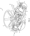
- FIG. 2 shows a cut-away view of one example of a valve actuator that may be incorporated by the present disclosure
- FIG. 3 shows a top perspective view of the PCB bulkhead assembly according to one aspect of the present disclosure
- FIG. 4 shows a bottom perspective view of the PCB bulkhead assembly of FIG. 3 , according to one aspect of the present disclosure
- FIG. 5 shows a cutaway view of the PCB bulkhead assembly of FIGS. 3 and 5 , along with a weather-proofing seal, according to one aspect of the present disclosure
- FIG. 6 shows a top elevation view of the PCB bulkhead assembly of FIG. 5 , according to one aspect of the present disclosure.
- FIG. 7 shows a bottom perspective view of the PCB bulkhead assembly of FIG. 5 and FIG. 6 with an explosion-proof seal that may also include a weatherproof feature, according to one aspect of the present disclosure.
- a valve actuator control 150 coupled to an electronic valve actuator 100 through a first bulkhead 200 A and a first PCB 330 A.
- the valve actuator control 150 further comprises a second bulkhead 200 B and a second PCB 330 B located between a first compartment 510 and a second compartment 520 of the valve actuator control 150 .
- the valve actuator 100 and the first bulkhead 200 A are connected to a valve (not shown) through a valve interface 190 .
- the actuator 100 includes circuitry formed on the first PCB 330 A of the first bulkhead 200 A which communicates between valve actuator control 150 and the valve actuator 100 .
- the first PCB 330 A of the valve actuator control 150 and the valve actuator 100 are shown located within a first PCB bulkhead assembly 300 A, which is configured to secure the first PCB 330 A within the first bulkhead 200 A.
- FIG. 2 shows a valve actuator 100 which could be incorporated in at least one embodiment according to the present disclosure.
- An optional hand wheel 101 attached to a drive sleeve 102 though a hand wheel adapter 111 may be used to manually control the electronic valve actuator.
- the housing 104 encapsulates the motor 114 which drives a motor drive shaft 109 and an optional worm shaft 103 to engage the worm gear 110 of the drive sleeve 102 or other supplemental actuation means.
- the motor drive shaft 109 then actuates the valve.
- a declutch handle 105 and a declutch mechanism 113 may also be included to engage and disengage the drive sleeve 102 or other supplemental actuation means.
- a gear key encoder 106 allows the electronic valve actuator 100 to achieve repeatable control of the actuation by sensing the valve position.
- the gear key encoder 106 may be included in a controller (not shown) which provides a means of controlling all or part of the electronic valve actuator 100 .
- the gear key encoder 106 may be programed by one or more logic elements, such as processors capable of executing machine readable instructions contained within PCBs 330 .
- the disclosed electronic valve actuator 100 of FIG. 2 also comprises a control module 108 , circuit board 115 , control panel 107 and display 112 , or may replace one or more of these elements with a PCB 330 or PCB bulkhead assembly 300 .
- the electronic valve actuator 100 is therefore capable of actuating a valve by receiving inputs from a PCB 330 to activate the motor 114 as required to actuate the valve through the motor drive shaft 109 according to the gear key encoder 106 .
- the use of the first PCB 330 A in this embodiment allows for separation of the valve actuator 100 and the valve actuator control 150 to prevent unwanted crossover interference of electronic signals through multiple wires, a waterproof seal, and an explosion-proof barrier.
- the second bulkhead 200 B is positioned between the first compartment 510 and the second compartment 520 of the valve actuator control 150 , where a customer has access to the first compartment 510 but where the second compartment 520 is inaccessible.
- a portion of the valve actuator 100 or the valve actuator control 150 that is inaccessible may restrict direct or indirect physical access or may restrict direct or indirect electrical or communication access.
- the first compartment 510 may comprise terminal blocks 600 to allow the customer to interface with the second PCB 330 B which will then communicate with the system of the second compartment 520 .
- the first compartment 510 may comprise a user interface 160 allowing access to the valve actuator control 150 to the customer, which may simplify the interaction with the first PCB 330 A and the valve actuator 100 , protected by a user access cover 165 .
- the first bulkhead 200 A is positioned between the second compartment 520 of the valve actuator control 150 and a third compartment 530 of the valve actuator 100 .
- the customer has access to neither compartment and the first PCB 330 A communicates between the valve actuator 100 and the valve actuator control 150 .
- the bulkhead 200 A 200 B can separate a user interface compartment from an internal compartment the customer is not intended to enter.
- the bulkhead 200 A 200 B may also separate two distinct internal electrical compartments that have weatherproof, flameproof, or explosion-proof capability and where access should be restricted.
- Bulkhead 200 A 200 B encompass passthrough connectors which facilitate data transfer between their two sides.
- the bulkhead passthrough allows for monitoring, actuation, communication, and other needed functions for the bulkhead 200 A 200 B.
- the passthrough connectors also allow for interfacing with terminal blocks 600 that may be integrated into the bulkhead 200 A 200 B.
- the first PCB bulkhead assembly 300 A may include seals to ensure the continued performance of the bulkhead and allow the two sides of the bulkhead to remain isolated from each other during operation.
- the first PCB bulkhead assembly 300 A further includes a sealant 350 A between at least the PCB retainer 320 A, the passthrough partition 310 A, and the PCB 330 A, which may be designed to form a weatherproof seal.
- the first PCB bulkhead assembly 300 A may further include an epoxy 360 A, which may be designed to form an explosion-proof seal.
- the first PCB bulkhead assembly 300 A may also include fasteners 340 A which secure the PCB retainer 320 A to the passthrough partition 310 A.
- the fasteners 340 A may be any suitable means for securing, such as bolts, screws, pins, and clamps or any other suitable means, and further may be released to allow the PCB retainer 320 A to be removed from the passthrough partition 310 A. It may be desirable to remove the PCB retainer 320 A so the PCB 330 A can be serviced or removed from the first PCB bulkhead assembly 300 A.
- the first PCB bulkhead assembly 300 A communicates with the electronic valve actuator 100 .
- Other types of equipment that can be controlled with the PCB 330 A, 330 B include pumps and valve positioners.
- the PCB 330 A, 330 B may interface with local control using knobs, touchscreen or rotary switches.
- the PCB 330 A 330 B may utilize remote control through wires connected to a remotely located control using knobs, touchscreen or rotary switches.
- the PCBs 330 A, 330 B may be controlled by wireless control.
- the PCBs 330 A, 330 B may utilize network control using wired or wireless inputs.
- the PCB bulkhead assembly 300 A 300 B may be assembled and ready for use with significantly less effort than a traditional bulkhead assembly.
- One method of assembly the first PCB bulkhead assembly 300 A as described herein is to first secure the first PCB 330 A within one or more sections of the PCB retainer 320 A.
- the PCB retainer 320 A may include [an] the aperture 325 A which is shaped to accept the first PCB 330 A, and is defined within the PCB retainer 320 A.
- the first PCB 330 A extends through the PCB retainer 320 A in order to allow communication between the two sides of the bulkhead.
- the PCB retainer 320 A is secured to the passthrough partition 310 A.
- the PCB retainer 320 A can be secured to the passthrough partition 310 A with the use of fasteners 340 A or any other suitable means. Furthermore, the fasteners 340 A may be releasable in order to allow the PCB retainer 320 A to be separated from the passthrough partition 310 A.
- the passthrough partition 310 A is then placed within the bulkhead where the passthrough partition 310 A separates the two sides of the bulkhead and the first PCB 330 A allows electrical signals to pass from one side of the bulkhead to the other, and secured to the bulkhead.
- a sealant 350 A may be applied to the first PCB bulkhead assembly 300 A to form a weather-proof seal while an epoxy 360 A may be applied to the first PCB bulkhead assembly 300 A to form an explosion-proof seal.
Landscapes
- Engineering & Computer Science (AREA)
- General Engineering & Computer Science (AREA)
- Microelectronics & Electronic Packaging (AREA)
- Chemical & Material Sciences (AREA)
- Dispersion Chemistry (AREA)
- Mechanical Engineering (AREA)
- Electrically Driven Valve-Operating Means (AREA)
- Indication Of The Valve Opening Or Closing Status (AREA)
Abstract
Description
-
- Referring next to
FIGS. 3 and 4 , the firstPCB bulkhead assembly 300A according to a first aspect of the present disclosure includes a bulkhead passthrough connector in the form of apassthrough partition 310A,PCB retainer 320A, andfirst PCB 330A. In one configuration, thepassthrough partition 310A is designed to be fitted securely within the space separating the two sides of a bulkhead (not shown). Additionally, thepassthrough partition 310A is contemplated to engage and secure thePCB retainer 320A. ThePCB retainer 320A, secured to thepassthrough partition 310A, maintains anaperture 325A defined within thePCB retainer 320A to cooperate and retain thefirst PCB 330A. ThePCB retainer 320A may include two or more separate sections to allow for ease of installation and securing to thepassthrough partition 310A. The use of more than one section for thePCB retainer 320A allows for simplified installation in thepassthrough partition 310A as well as a simplified connection between thePCB retainer 320A and thePCB 330A. Finally, thefirst PCB 330A is coupled to thePCB retainer 320A as it extends from one side of the bulkhead to the other, allowing for communication of the signals sent through thefirst PCB 330A between the separate sides of thefirst bulkhead 200A.
- Referring next to
-
- Regarding the
PCB PCB PCB PCB PCB PCB 330A, along axis z ofFIG. 3 , minimizes bulkhead area to allow a maximum number of electrical signals and power to pass through an explosion-proof and waterproof barrier while minimizing the bulkhead surface area of the assembly. These configurations allow the passthrough to be used in high pressure containment applications in order to reduce the likelihood of leakage. Additionally, while an explosion-proof or waterproof seal may be used, applications requiring a weather-proof seal may also be used as a platform for thePCB 300B and thebulkhead assembly 300Arespective PCB - In another embodiment, applying industry standard PCB layout techniques, such as RF strip-line and micro-strip, to the
PCB 330APCB 330APCB 330A - Additionally, the
PCB 330APCB 330APCB 330A - The
PCB bulkhead assembly PCB bulkhead assembly PCB 330APCB bulkhead assembly FIG. 1 ) for interface may be soldered to thePCB 330Aterminal block 600 allows for the interface between third-part equipment and thePCB 330APCB bulkhead assembly PCB bulkhead assembly
- Regarding the
Claims (12)
Priority Applications (3)
| Application Number | Priority Date | Filing Date | Title |
|---|---|---|---|
| US15/985,754 US11063382B2 (en) | 2018-05-22 | 2018-05-22 | Waterproof and explosion-proof circuit board and electronic valve actuator for flow control applications |
| PCT/US2019/033061 WO2019226518A1 (en) | 2018-05-22 | 2019-05-20 | Waterproof and explosion-proof circuit board and electronic valve actuator for flow control applications |
| US17/343,282 US11552422B2 (en) | 2018-05-22 | 2021-06-09 | Waterproof and explosion-proof circuit board and electronic valve actuator for flow control applications |
Applications Claiming Priority (1)
| Application Number | Priority Date | Filing Date | Title |
|---|---|---|---|
| US15/985,754 US11063382B2 (en) | 2018-05-22 | 2018-05-22 | Waterproof and explosion-proof circuit board and electronic valve actuator for flow control applications |
Related Child Applications (1)
| Application Number | Title | Priority Date | Filing Date |
|---|---|---|---|
| US17/343,282 Division US11552422B2 (en) | 2018-05-22 | 2021-06-09 | Waterproof and explosion-proof circuit board and electronic valve actuator for flow control applications |
Publications (2)
| Publication Number | Publication Date |
|---|---|
| US20190363475A1 US20190363475A1 (en) | 2019-11-28 |
| US11063382B2 true US11063382B2 (en) | 2021-07-13 |
Family
ID=67060458
Family Applications (2)
| Application Number | Title | Priority Date | Filing Date |
|---|---|---|---|
| US15/985,754 Active 2039-02-01 US11063382B2 (en) | 2018-05-22 | 2018-05-22 | Waterproof and explosion-proof circuit board and electronic valve actuator for flow control applications |
| US17/343,282 Active 2038-05-31 US11552422B2 (en) | 2018-05-22 | 2021-06-09 | Waterproof and explosion-proof circuit board and electronic valve actuator for flow control applications |
Family Applications After (1)
| Application Number | Title | Priority Date | Filing Date |
|---|---|---|---|
| US17/343,282 Active 2038-05-31 US11552422B2 (en) | 2018-05-22 | 2021-06-09 | Waterproof and explosion-proof circuit board and electronic valve actuator for flow control applications |
Country Status (2)
| Country | Link |
|---|---|
| US (2) | US11063382B2 (en) |
| WO (1) | WO2019226518A1 (en) |
Citations (11)
| Publication number | Priority date | Publication date | Assignee | Title |
|---|---|---|---|---|
| US4549108A (en) | 1982-06-04 | 1985-10-22 | U.S. Philips Corporation | Multichannel X-ray detector with multiple electrical feedthrough members |
| US5727110A (en) | 1995-09-29 | 1998-03-10 | Rosemount Inc. | Electro-optic interface for field instrument |
| US20110317390A1 (en) * | 2010-06-21 | 2011-12-29 | Endress + Hauser Flowtec Ag | Electronics housing for an electronic device, and a device formed therewith |
| US8354587B2 (en) * | 2005-10-28 | 2013-01-15 | Fei Company | Hermetically sealed housing with electrical feed-in |
| US20150340133A1 (en) | 2013-02-07 | 2015-11-26 | Olympus Winter & Ibe Gmbh | Hermetic feedthrough, method for producing a hermetic feedthrough, printed circuit board and surgical instrument |
| US20160111814A1 (en) | 2014-10-20 | 2016-04-21 | HGST Netherlands B.V. | Feedthrough connector for hermetically sealed electronic devices |
| US9541428B2 (en) * | 2012-09-10 | 2017-01-10 | Endress + Hauser Flowtec Ag | Interface between a sensor unit and an explosion resistant housing |
| US9554483B2 (en) * | 2012-09-10 | 2017-01-24 | Endress + Hauser Flowtec Ag | Electronic device having a housing for accommodating electronic components, preferably of a process transmitter |
| US20190063964A1 (en) * | 2017-08-30 | 2019-02-28 | Nidec Motor Corporation | Intrinsically-safe, explosion-proof encoder |
| US20190082529A1 (en) * | 2017-09-11 | 2019-03-14 | Apple Inc. | Space-efficient flex cable with improved signal integrity for a portable electronic device |
| US10670433B2 (en) * | 2015-12-21 | 2020-06-02 | Endress + Hauser Flowtec Ag | Housing for a field device |
Family Cites Families (2)
| Publication number | Priority date | Publication date | Assignee | Title |
|---|---|---|---|---|
| JP5969405B2 (en) * | 2013-01-30 | 2016-08-17 | 日立オートモティブシステムズ株式会社 | Automotive electronic module |
| JP6435420B2 (en) * | 2015-09-30 | 2018-12-05 | 日立オートモティブシステムズ株式会社 | Resin molded body and sensor device |
-
2018
- 2018-05-22 US US15/985,754 patent/US11063382B2/en active Active
-
2019
- 2019-05-20 WO PCT/US2019/033061 patent/WO2019226518A1/en not_active Ceased
-
2021
- 2021-06-09 US US17/343,282 patent/US11552422B2/en active Active
Patent Citations (11)
| Publication number | Priority date | Publication date | Assignee | Title |
|---|---|---|---|---|
| US4549108A (en) | 1982-06-04 | 1985-10-22 | U.S. Philips Corporation | Multichannel X-ray detector with multiple electrical feedthrough members |
| US5727110A (en) | 1995-09-29 | 1998-03-10 | Rosemount Inc. | Electro-optic interface for field instrument |
| US8354587B2 (en) * | 2005-10-28 | 2013-01-15 | Fei Company | Hermetically sealed housing with electrical feed-in |
| US20110317390A1 (en) * | 2010-06-21 | 2011-12-29 | Endress + Hauser Flowtec Ag | Electronics housing for an electronic device, and a device formed therewith |
| US9541428B2 (en) * | 2012-09-10 | 2017-01-10 | Endress + Hauser Flowtec Ag | Interface between a sensor unit and an explosion resistant housing |
| US9554483B2 (en) * | 2012-09-10 | 2017-01-24 | Endress + Hauser Flowtec Ag | Electronic device having a housing for accommodating electronic components, preferably of a process transmitter |
| US20150340133A1 (en) | 2013-02-07 | 2015-11-26 | Olympus Winter & Ibe Gmbh | Hermetic feedthrough, method for producing a hermetic feedthrough, printed circuit board and surgical instrument |
| US20160111814A1 (en) | 2014-10-20 | 2016-04-21 | HGST Netherlands B.V. | Feedthrough connector for hermetically sealed electronic devices |
| US10670433B2 (en) * | 2015-12-21 | 2020-06-02 | Endress + Hauser Flowtec Ag | Housing for a field device |
| US20190063964A1 (en) * | 2017-08-30 | 2019-02-28 | Nidec Motor Corporation | Intrinsically-safe, explosion-proof encoder |
| US20190082529A1 (en) * | 2017-09-11 | 2019-03-14 | Apple Inc. | Space-efficient flex cable with improved signal integrity for a portable electronic device |
Non-Patent Citations (1)
| Title |
|---|
| International Search Report and Written Opinion dated Oct. 11, 2019 in co-pending International Application No. PCT/US2018/033061. |
Also Published As
| Publication number | Publication date |
|---|---|
| US20190363475A1 (en) | 2019-11-28 |
| WO2019226518A1 (en) | 2019-11-28 |
| US11552422B2 (en) | 2023-01-10 |
| US20210296811A1 (en) | 2021-09-23 |
Similar Documents
| Publication | Publication Date | Title |
|---|---|---|
| US6704815B1 (en) | Input-output unit for serial-parallel signal conversion | |
| US9320165B2 (en) | Housing cover panel for accommodating plug-in modules | |
| US7120030B2 (en) | Housing structure of vehicle-mounted electronic equipment | |
| US5482362A (en) | Anti-lock brake control valve control module | |
| US8111527B2 (en) | Standardized support element with integrated interface | |
| JPH08121323A (en) | Hydraulic pump assembly | |
| US20150085449A1 (en) | Industrial process fluid device with humidity-sealed electronics module | |
| CN104718806B (en) | With the electronic device for accommodating electronic unit, the housing of preferred process transmitter | |
| US7885080B2 (en) | System component of a control device | |
| JP3399878B2 (en) | Manifold solenoid valve with relay device | |
| WO2021253752A1 (en) | Controller and movable platform | |
| US10759365B2 (en) | Power electronics module and hybrid module with an electrical signal and/or clutch actuator connection | |
| CN103636086A (en) | Sealed plug-in circuit breaker assembly | |
| US6513547B2 (en) | Solenoid-operated valve manifold | |
| JP4661278B2 (en) | Turbo molecular pump | |
| US7920389B2 (en) | Board hardware device and radio frequency blind-mate connection device | |
| US11552422B2 (en) | Waterproof and explosion-proof circuit board and electronic valve actuator for flow control applications | |
| CN105555072A (en) | Electrical box and air conditioner with same | |
| US20140209825A1 (en) | System and method for remote control and monitoring of a valve | |
| US8810090B2 (en) | Frequency converter assembly having converter housing attached through intermediate component to motor housing | |
| US6545860B1 (en) | Automation control enclosure having a glandplate to facilitate input and output connections | |
| US10302212B2 (en) | Servomotor for industrial valve or leaf with connecting card and connector | |
| CN112385325B (en) | Operating device and process valve assembly | |
| CN113815418A (en) | Control unit and electric heating | |
| US11745676B2 (en) | Motor vehicle locking device |
Legal Events
| Date | Code | Title | Description |
|---|---|---|---|
| FEPP | Fee payment procedure |
Free format text: ENTITY STATUS SET TO UNDISCOUNTED (ORIGINAL EVENT CODE: BIG.); ENTITY STATUS OF PATENT OWNER: LARGE ENTITY |
|
| AS | Assignment |
Owner name: FLOWSERVE MANAGEMENT COMPANY, TEXAS Free format text: ASSIGNMENT OF ASSIGNORS INTEREST;ASSIGNORS:GORBUTT, MICHAEL;HOOSS, WILLIAM;MORRIS, DAN;REEL/FRAME:047409/0648 Effective date: 20160614 |
|
| STPP | Information on status: patent application and granting procedure in general |
Free format text: NON FINAL ACTION MAILED |
|
| STPP | Information on status: patent application and granting procedure in general |
Free format text: RESPONSE TO NON-FINAL OFFICE ACTION ENTERED AND FORWARDED TO EXAMINER |
|
| STPP | Information on status: patent application and granting procedure in general |
Free format text: NOTICE OF ALLOWANCE MAILED -- APPLICATION RECEIVED IN OFFICE OF PUBLICATIONS |
|
| STPP | Information on status: patent application and granting procedure in general |
Free format text: PUBLICATIONS -- ISSUE FEE PAYMENT RECEIVED |
|
| STPP | Information on status: patent application and granting procedure in general |
Free format text: PUBLICATIONS -- ISSUE FEE PAYMENT VERIFIED |
|
| STPP | Information on status: patent application and granting procedure in general |
Free format text: NOTICE OF ALLOWANCE MAILED -- APPLICATION RECEIVED IN OFFICE OF PUBLICATIONS |
|
| STPP | Information on status: patent application and granting procedure in general |
Free format text: PUBLICATIONS -- ISSUE FEE PAYMENT VERIFIED |
|
| STCF | Information on status: patent grant |
Free format text: PATENTED CASE |
|
| MAFP | Maintenance fee payment |
Free format text: PAYMENT OF MAINTENANCE FEE, 4TH YEAR, LARGE ENTITY (ORIGINAL EVENT CODE: M1551); ENTITY STATUS OF PATENT OWNER: LARGE ENTITY Year of fee payment: 4 |