US11060331B2 - Engine door and latch assembly - Google Patents
Engine door and latch assembly Download PDFInfo
- Publication number
- US11060331B2 US11060331B2 US14/907,076 US201314907076A US11060331B2 US 11060331 B2 US11060331 B2 US 11060331B2 US 201314907076 A US201314907076 A US 201314907076A US 11060331 B2 US11060331 B2 US 11060331B2
- Authority
- US
- United States
- Prior art keywords
- door
- strike
- latch
- latch assembly
- seat
- Prior art date
- Legal status (The legal status is an assumption and is not a legal conclusion. Google has not performed a legal analysis and makes no representation as to the accuracy of the status listed.)
- Active, expires
Links
Images


Classifications
-
- B—PERFORMING OPERATIONS; TRANSPORTING
- B64—AIRCRAFT; AVIATION; COSMONAUTICS
- B64C—AEROPLANES; HELICOPTERS
- B64C1/00—Fuselages; Constructional features common to fuselages, wings, stabilising surfaces or the like
- B64C1/14—Windows; Doors; Hatch covers or access panels; Surrounding frame structures; Canopies; Windscreens accessories therefor, e.g. pressure sensors, water deflectors, hinges, seals, handles, latches, windscreen wipers
- B64C1/1407—Doors; surrounding frames
- B64C1/1446—Inspection hatches
-
- E—FIXED CONSTRUCTIONS
- E05—LOCKS; KEYS; WINDOW OR DOOR FITTINGS; SAFES
- E05C—BOLTS OR FASTENING DEVICES FOR WINGS, SPECIALLY FOR DOORS OR WINDOWS
- E05C19/00—Other devices specially designed for securing wings, e.g. with suction cups
- E05C19/10—Hook fastenings; Fastenings in which a link engages a fixed hook-like member
- E05C19/12—Hook fastenings; Fastenings in which a link engages a fixed hook-like member pivotally mounted around an axis
-
- B—PERFORMING OPERATIONS; TRANSPORTING
- B64—AIRCRAFT; AVIATION; COSMONAUTICS
- B64D—EQUIPMENT FOR FITTING IN OR TO AIRCRAFT; FLIGHT SUITS; PARACHUTES; ARRANGEMENT OR MOUNTING OF POWER PLANTS OR PROPULSION TRANSMISSIONS IN AIRCRAFT
- B64D29/00—Power-plant nacelles, fairings or cowlings
- B64D29/08—Inspection panels for power plants
-
- E—FIXED CONSTRUCTIONS
- E05—LOCKS; KEYS; WINDOW OR DOOR FITTINGS; SAFES
- E05B—LOCKS; ACCESSORIES THEREFOR; HANDCUFFS
- E05B15/00—Other details of locks; Parts for engagement by bolts of fastening devices
- E05B15/02—Striking-plates; Keepers; Bolt staples; Escutcheons
- E05B15/0205—Striking-plates, keepers, staples
- E05B15/022—Striking-plates, keepers, staples movable, resilient or yieldable
-
- E—FIXED CONSTRUCTIONS
- E05—LOCKS; KEYS; WINDOW OR DOOR FITTINGS; SAFES
- E05B—LOCKS; ACCESSORIES THEREFOR; HANDCUFFS
- E05B65/00—Locks or fastenings for special use
- E05B65/10—Locks or fastenings for special use for panic or emergency doors
- E05B65/102—Locks or fastenings for special use for panic or emergency doors opening under pressure on the surface of the door itself
-
- E—FIXED CONSTRUCTIONS
- E05—LOCKS; KEYS; WINDOW OR DOOR FITTINGS; SAFES
- E05C—BOLTS OR FASTENING DEVICES FOR WINGS, SPECIALLY FOR DOORS OR WINDOWS
- E05C17/00—Devices for holding wings open; Devices for limiting opening of wings or for holding wings open by a movable member extending between frame and wing; Braking devices, stops or buffers, combined therewith
- E05C17/02—Devices for holding wings open; Devices for limiting opening of wings or for holding wings open by a movable member extending between frame and wing; Braking devices, stops or buffers, combined therewith by mechanical means
- E05C17/04—Devices for holding wings open; Devices for limiting opening of wings or for holding wings open by a movable member extending between frame and wing; Braking devices, stops or buffers, combined therewith by mechanical means with a movable bar or equivalent member extending between frame and wing
- E05C17/36—Devices for holding wings open; Devices for limiting opening of wings or for holding wings open by a movable member extending between frame and wing; Braking devices, stops or buffers, combined therewith by mechanical means with a movable bar or equivalent member extending between frame and wing comprising a flexible member, e.g. chains
-
- E—FIXED CONSTRUCTIONS
- E05—LOCKS; KEYS; WINDOW OR DOOR FITTINGS; SAFES
- E05C—BOLTS OR FASTENING DEVICES FOR WINGS, SPECIALLY FOR DOORS OR WINDOWS
- E05C3/00—Fastening devices with bolts moving pivotally or rotatively
- E05C3/12—Fastening devices with bolts moving pivotally or rotatively with latching action
- E05C3/16—Fastening devices with bolts moving pivotally or rotatively with latching action with operating handle or equivalent member moving otherwise than rigidly with the latch
-
- E—FIXED CONSTRUCTIONS
- E05—LOCKS; KEYS; WINDOW OR DOOR FITTINGS; SAFES
- E05C—BOLTS OR FASTENING DEVICES FOR WINGS, SPECIALLY FOR DOORS OR WINDOWS
- E05C17/00—Devices for holding wings open; Devices for limiting opening of wings or for holding wings open by a movable member extending between frame and wing; Braking devices, stops or buffers, combined therewith
- E05C17/02—Devices for holding wings open; Devices for limiting opening of wings or for holding wings open by a movable member extending between frame and wing; Braking devices, stops or buffers, combined therewith by mechanical means
- E05C17/04—Devices for holding wings open; Devices for limiting opening of wings or for holding wings open by a movable member extending between frame and wing; Braking devices, stops or buffers, combined therewith by mechanical means with a movable bar or equivalent member extending between frame and wing
- E05C17/12—Devices for holding wings open; Devices for limiting opening of wings or for holding wings open by a movable member extending between frame and wing; Braking devices, stops or buffers, combined therewith by mechanical means with a movable bar or equivalent member extending between frame and wing consisting of a single rod
- E05C17/16—Devices for holding wings open; Devices for limiting opening of wings or for holding wings open by a movable member extending between frame and wing; Braking devices, stops or buffers, combined therewith by mechanical means with a movable bar or equivalent member extending between frame and wing consisting of a single rod pivoted only at one end and having an elongated slot
-
- E—FIXED CONSTRUCTIONS
- E05—LOCKS; KEYS; WINDOW OR DOOR FITTINGS; SAFES
- E05C—BOLTS OR FASTENING DEVICES FOR WINGS, SPECIALLY FOR DOORS OR WINDOWS
- E05C9/00—Arrangements of simultaneously actuated bolts or other securing devices at well-separated positions on the same wing
- E05C9/20—Coupling means for sliding bars, rods, or cables
-
- E—FIXED CONSTRUCTIONS
- E05—LOCKS; KEYS; WINDOW OR DOOR FITTINGS; SAFES
- E05C—BOLTS OR FASTENING DEVICES FOR WINGS, SPECIALLY FOR DOORS OR WINDOWS
- E05C9/00—Arrangements of simultaneously actuated bolts or other securing devices at well-separated positions on the same wing
- E05C9/22—Guides for sliding bars, rods or cables
-
- E—FIXED CONSTRUCTIONS
- E05—LOCKS; KEYS; WINDOW OR DOOR FITTINGS; SAFES
- E05C—BOLTS OR FASTENING DEVICES FOR WINGS, SPECIALLY FOR DOORS OR WINDOWS
- E05C9/00—Arrangements of simultaneously actuated bolts or other securing devices at well-separated positions on the same wing
- E05C9/24—Means for transmitting movements between vertical and horizontal sliding bars, rods or cables for the fastening of wings, e.g. corner guides
-
- Y—GENERAL TAGGING OF NEW TECHNOLOGICAL DEVELOPMENTS; GENERAL TAGGING OF CROSS-SECTIONAL TECHNOLOGIES SPANNING OVER SEVERAL SECTIONS OF THE IPC; TECHNICAL SUBJECTS COVERED BY FORMER USPC CROSS-REFERENCE ART COLLECTIONS [XRACs] AND DIGESTS
- Y10—TECHNICAL SUBJECTS COVERED BY FORMER USPC
- Y10S—TECHNICAL SUBJECTS COVERED BY FORMER USPC CROSS-REFERENCE ART COLLECTIONS [XRACs] AND DIGESTS
- Y10S292/00—Closure fasteners
- Y10S292/65—Emergency or safety
-
- Y—GENERAL TAGGING OF NEW TECHNOLOGICAL DEVELOPMENTS; GENERAL TAGGING OF CROSS-SECTIONAL TECHNOLOGIES SPANNING OVER SEVERAL SECTIONS OF THE IPC; TECHNICAL SUBJECTS COVERED BY FORMER USPC CROSS-REFERENCE ART COLLECTIONS [XRACs] AND DIGESTS
- Y10—TECHNICAL SUBJECTS COVERED BY FORMER USPC
- Y10T—TECHNICAL SUBJECTS COVERED BY FORMER US CLASSIFICATION
- Y10T292/00—Closure fasteners
- Y10T292/03—Miscellaneous
-
- Y—GENERAL TAGGING OF NEW TECHNOLOGICAL DEVELOPMENTS; GENERAL TAGGING OF CROSS-SECTIONAL TECHNOLOGIES SPANNING OVER SEVERAL SECTIONS OF THE IPC; TECHNICAL SUBJECTS COVERED BY FORMER USPC CROSS-REFERENCE ART COLLECTIONS [XRACs] AND DIGESTS
- Y10—TECHNICAL SUBJECTS COVERED BY FORMER USPC
- Y10T—TECHNICAL SUBJECTS COVERED BY FORMER US CLASSIFICATION
- Y10T292/00—Closure fasteners
- Y10T292/08—Bolts
- Y10T292/087—Loops
-
- Y—GENERAL TAGGING OF NEW TECHNOLOGICAL DEVELOPMENTS; GENERAL TAGGING OF CROSS-SECTIONAL TECHNOLOGIES SPANNING OVER SEVERAL SECTIONS OF THE IPC; TECHNICAL SUBJECTS COVERED BY FORMER USPC CROSS-REFERENCE ART COLLECTIONS [XRACs] AND DIGESTS
- Y10—TECHNICAL SUBJECTS COVERED BY FORMER USPC
- Y10T—TECHNICAL SUBJECTS COVERED BY FORMER US CLASSIFICATION
- Y10T292/00—Closure fasteners
- Y10T292/28—Extension link
Definitions
- Contemporary aircraft may include engines with pressure relief systems. For example, a sudden pressure rise may occur in a nacelle compartment of the engine and this may cause stresses in the compartment which may result in failure of nacelle components or unacceptable deformation of the nacelle. Accordingly, the engine typically features some means for pressure relief to prevent damage to nacelle components.
- Embodiments of the innovation relate to a latch assembly for a door pivotally mounted to a surrounding structure for pivotal movement between an opened position and a closed position
- the latch assembly includes a latch keep carried by one of the door and the structure and having a removable strike located within a strike seat, a latch carried by the other of the door and the structure and having a catch configured to engage the strike, and a cable having a first portion secured to the other of the door and structure and a second portion carrying the strike.
- the strike is located within the strike seat and the catch will engage the strike and latch the door in the closed position thereby ensuring a coupling of the cable between the door and the structure.
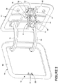
- FIG. 1 is a bottom view of a door and a latch assembly with the door in a closed position in accordance with various aspects described herein.
- FIG. 2 is a perspective view of the door in an opened position in accordance with various aspects described herein.
- FIGS. 3A and 3B illustrate perspective views of portions of the latch assembly in accordance with various aspects described herein.
- FIG. 4 is a partial perspective view of a pin before it is mounted in a strike seat of the latch assembly in accordance with various aspects described herein.
- FIGS. 5A, 5B, 5C and 5D are views of the door in a closed position in accordance with various aspects described herein.
- FIGS. 6A and 6B are views of the door in an opened position and acting as a pressure relief door in accordance with various aspects described herein.
- FIG. 1 illustrates a latch assembly 10 for a door 12 , which is pivotally mounted to a surrounding structure 14 .
- the door 12 may be pivotally mounted to any suitable surrounding structure in any suitable manner including through use of hinges 16 .
- the door 12 may be pivotally mounted to a portion of a nacelle 18 of an aircraft engine, which forms the surrounding structure 14 .
- the door 12 may provide access to an oil tank and may be pivoted 90° to a fully open position (i.e., a second open position) so that a user may have access to an oil tank on the engine.
- the door 12 may be pivotally mounted for pivotal movement between a closed position as shown in FIG. 1 and an a second opened position as shown in FIG. 2 .
- FIG. 3A illustrates a latch keep 20 that may form a portion of the latch assembly 10 and may be carried by one of the door 12 and the surrounding structure 14 .
- a strike seat 22 of the latch keep 20 may be formed to retain a strike 24 ( FIG. 3B ) that may be removably received in the strike seat 22 .
- the latch keep 20 is operably coupled with the surrounding structure 14 .
- the latch keep 20 and its strike seat 22 may be formed in any suitable manner.
- the strike seat 22 may include a hook 26 for receiving the strike 24 .
- the strike seat 22 has been shown as including a pair of spaced hooks 26 . The hooks 26 are oriented such that each hook 26 opens non-aligned from a pivoting direction of the door 12 from the closed position to the opened position.
- FIG. 3B illustrates a latch 30 that may form another portion of the latch assembly 10 and may be carried by the other of the door 12 and the surrounding structure 14 .
- the latch 30 is carried by the door 12 .
- a catch 32 is included in the latch 30 and is configured to engage the strike 24 .
- the catch 32 may be any suitable catch capable of engaging and retaining the strike 24 .
- a cable 34 having a first portion 36 which is also secured to the other of the door 12 and surrounding structure 14 and in the illustrated example, is coupled with the door 12 .
- a second portion 38 of the cable 34 carries the strike 24 of the latch assembly 10 .
- the strike 24 may take any suitable form, including that the strike 24 may include a pin 44 .
- the second portion 38 of the cable 34 may have first and second spaced strands 40 and 42 with the pin 44 spanning the first and second spaced strands 40 and 42 .
- the first and second spaced strands 40 and 42 may extend the length of the cable 34 and each of the first and second spaced strands 40 and 42 has a second end connected to the pin 44 and a first end connected to the door 12 . More specifically, the first end of the first and second spaced strands 40 and 42 , corresponding to the first portion 36 , is connected to an inner surface of the door 12 .
- FIG. 4 When beginning to close the door 12 , as is shown in FIG. 4 , a user may place the strike 24 into the strike seat 22 .
- the strike 24 When the strike 24 is located within the strike seat 22 , the user may shut the door, which moves the catch 32 to engage the strike 24 and latch the door 12 in the closed position, as shown in FIG. 5A . If the strike 24 is not retained by the latch keep 20 , the latch assembly 10 cannot be locked. This ensures the user must couple the cable 34 between the door 12 and the surrounding structure 14 in order to latch the door.
- FIGS. 5B and 5C show additional views of the strike 24 retained by the latch keep 20 and the catch 32 engaging the strike 24 . Further, the hook 26 of the strike seat 22 may be oriented such that contacting of the pin 44 with the catch 32 presses the pin 44 into the strike seat 22 as more clearly seen in FIG. 5D .
- the door 12 may be moved to a first opened position and may act as pressure relief door.
- the latch keep 20 retains the pin 44 when the door 12 is moved to the first opened position.
- FIG. 6B illustrates that the hooks 26 continue to retain the strike 24 when the door 12 is moved to the first opened position.
- the latch assembly 10 may be operable between a latch position, where the door 12 is held in the closed position, and a release position, where the door 12 may be pivoted to the first opened position.
- the embodiments described above provide for a variety of benefits including that the embodiments ensure a coupling of the cable between the door and the structure such that when the door works as pressure relief door the cable may limit the open angle of the door and make sure during the pressure relief process that the no damage will occur.
- the embodiments ensure a coupling of the cable between the door and the structure such that when the door works as pressure relief door the cable may limit the open angle of the door and make sure during the pressure relief process that the no damage will occur.
- the embodiments ensure a coupling of the cable between the door and the structure such that when the door works as pressure relief door the cable may limit the open angle of the door and make sure during the pressure relief process that the no damage will occur.
- the embodiments ensure a coupling of the cable between the door and the structure such that when the door works as pressure relief door the cable may limit the open angle of the door and make sure during the pressure relief process that the no damage will occur.
- the embodiments ensure the cable is connected between the door and the structure.
Landscapes
- Engineering & Computer Science (AREA)
- Mechanical Engineering (AREA)
- Aviation & Aerospace Engineering (AREA)
- Business, Economics & Management (AREA)
- Emergency Management (AREA)
- Lock And Its Accessories (AREA)
- Superstructure Of Vehicle (AREA)
Abstract
Description
Claims (16)
Applications Claiming Priority (1)
| Application Number | Priority Date | Filing Date | Title |
|---|---|---|---|
| PCT/CN2013/079996 WO2015010271A1 (en) | 2013-07-24 | 2013-07-24 | Engine door and latch assembly |
Publications (2)
| Publication Number | Publication Date |
|---|---|
| US20160145918A1 US20160145918A1 (en) | 2016-05-26 |
| US11060331B2 true US11060331B2 (en) | 2021-07-13 |
Family
ID=52392590
Family Applications (1)
| Application Number | Title | Priority Date | Filing Date |
|---|---|---|---|
| US14/907,076 Active 2035-11-20 US11060331B2 (en) | 2013-07-24 | 2013-07-24 | Engine door and latch assembly |
Country Status (5)
| Country | Link |
|---|---|
| US (1) | US11060331B2 (en) |
| EP (1) | EP3025002B1 (en) |
| CN (1) | CN105378201B (en) |
| CA (1) | CA2918310C (en) |
| WO (1) | WO2015010271A1 (en) |
Cited By (1)
| Publication number | Priority date | Publication date | Assignee | Title |
|---|---|---|---|---|
| EP4129825A1 (en) * | 2021-08-03 | 2023-02-08 | Airbus Operations SAS | Assembly for a nacelle of an aircraft engine, said assembly comprising a fixed cover and a mobile cover mounted on the fixed cover |
Families Citing this family (13)
| Publication number | Priority date | Publication date | Assignee | Title |
|---|---|---|---|---|
| CN106080795A (en) * | 2016-07-15 | 2016-11-09 | 青岛雷沃挖掘机有限公司 | A kind of excavator enging cabin and lateral open-close type front cover thereof |
| US10173783B2 (en) * | 2016-08-23 | 2019-01-08 | Airbus Helicopters | Rotorcraft with cowling able to rotate and translate relative to the fuselage |
| KR101979332B1 (en) * | 2016-08-23 | 2019-08-28 | 에어버스 헬리콥터스 | Rotorcraft with cowling able to rotate and translate relative to the fuselage |
| US10634060B2 (en) | 2016-11-20 | 2020-04-28 | Mra Systems, Llc | Engine door with burst seal |
| GB201704841D0 (en) * | 2017-03-27 | 2017-05-10 | Rolls Royce Plc | Gas Turbine Engine |
| US10640223B2 (en) | 2017-08-22 | 2020-05-05 | Rohr, Inc. | Safety maintenance panel for a thrust reverser |
| FR3071821B1 (en) * | 2017-09-29 | 2019-10-04 | Airbus Operations | DOUBLE FLOW TURBOREACTOR FOR AN AIRCRAFT WITH IMPROVED OPENING |
| GB201720831D0 (en) | 2017-10-12 | 2018-01-31 | Rolls-Royce Ltd | A pressure relief arrangement for a gas turbine engine |
| FR3081837B1 (en) * | 2018-06-05 | 2020-11-27 | Airbus Operations Sas | AIRCRAFT TURBOMACHINE ASSEMBLY WITH ARTICULATED HOOD |
| US10774681B1 (en) | 2019-03-12 | 2020-09-15 | Rohr, Inc. | Pressure relief door rotating exhaust deflector |
| US11268406B2 (en) * | 2019-08-12 | 2022-03-08 | The Boeing Company | Movement-limiting device for a turbine engine and associated method |
| JP7183431B2 (en) * | 2020-07-30 | 2022-12-05 | チュン リー,サン | Bi-directional door spacing adjuster for restricting pet movement |
| KR102177791B1 (en) * | 2020-07-30 | 2020-11-11 | 이상춘 | Two-way swing door opening gap control for companion animal movement limit |
Citations (57)
| Publication number | Priority date | Publication date | Assignee | Title |
|---|---|---|---|---|
| US2973217A (en) * | 1959-07-23 | 1961-02-28 | Arnold E Gregoire | Automobile trunk lid holder kit |
| US3585757A (en) * | 1969-07-03 | 1971-06-22 | Mc Donnell Douglas Corp | Overhead opening plug door |
| US3851845A (en) * | 1972-04-17 | 1974-12-03 | Westland Aircraft Ltd | Aperture closure devices |
| US4086726A (en) * | 1976-04-22 | 1978-05-02 | The Bkm Company | Aircraft door counterbalance system |
| US4088288A (en) * | 1977-04-27 | 1978-05-09 | The Boeing Company | Aircraft ramp assembly |
| US4125235A (en) * | 1977-04-04 | 1978-11-14 | The Boeing Company | Apparatus for opening an aircraft door and for arming and disarming an escape slide deploying mechanism |
| US4167258A (en) * | 1978-03-24 | 1979-09-11 | Lockheed Corporation | Aft cargo door for aircraft |
| US4375876A (en) * | 1981-06-04 | 1983-03-08 | The Boeing Company | Overhead sliding door and foldable cabin panel assembly for an airplane |
| US4470566A (en) * | 1982-08-20 | 1984-09-11 | The Boeing Company | Plug-type aircraft door actuating mechanism |
| US4497462A (en) * | 1983-03-28 | 1985-02-05 | The Boeing Company | Outward opening electrically powered plug-type cargo door |
| US4613099A (en) | 1982-02-05 | 1986-09-23 | The Boeing Company | Latch signal and cowling structure |
| US4666194A (en) * | 1984-11-03 | 1987-05-19 | Charman John C | Trunk lid fastening device for automobiles |
| US4667993A (en) * | 1984-11-15 | 1987-05-26 | Hannesson James H | Trunk lid holding device |
| US4825644A (en) | 1987-11-12 | 1989-05-02 | United Technologies Corporation | Ventilation system for a nacelle |
| US4989808A (en) * | 1989-07-07 | 1991-02-05 | Msa Aircraft Interior Products, Inc. | Sliding pocket door for aircraft use capable of non-destructive blow-out |
| US5064147A (en) * | 1990-02-12 | 1991-11-12 | The Boeing Company | Upwardly opening plug-type door for use as an over-wing emergency hatch |
| US5163724A (en) * | 1991-11-14 | 1992-11-17 | Daniel Conte | Vehicle trunk compartment lid holder |
| US5228737A (en) * | 1992-06-25 | 1993-07-20 | Zimmerman Neil L | Vehicle trunk lid holder |
| US5297828A (en) * | 1992-12-31 | 1994-03-29 | Chung Thomas I | Vehicle trunk lid securing apparatus |
| US5647619A (en) * | 1996-06-21 | 1997-07-15 | Pyramid Industries Ltd. | Automobile trunk lock tie-down |
| US5707095A (en) * | 1996-04-08 | 1998-01-13 | Pribak; Martin S. | Dual function striker pin for vehicle tailgate assembly |
| US6189832B1 (en) | 1998-04-03 | 2001-02-20 | Hartwell Corporation | Permanently connected remote latch mechanism |
| US6267429B1 (en) * | 2000-10-27 | 2001-07-31 | Ford Global Technologies, Inc. | Multi-position vehicle tailgate assembly |
| US6428062B1 (en) * | 2000-01-07 | 2002-08-06 | Steven G. Roehl | Truck lid holder for vehicles |
| US6598436B2 (en) * | 1999-06-04 | 2003-07-29 | Volvo Car Corporation | Vehicle lock device |
| US6648381B2 (en) * | 2001-06-19 | 2003-11-18 | Charles J. Holton | Trunk tie-down |
| US20040012208A1 (en) | 2002-04-01 | 2004-01-22 | Antonio Ruiz | Externally adjustable latch |
| US7093876B2 (en) * | 2004-06-29 | 2006-08-22 | Honda Motor Co., Ltd. | Tailgate lift-assist assembly |
| US20070095985A1 (en) * | 2002-12-11 | 2007-05-03 | Eurocopter Deutschland Gmbh | Aircraft door arrangement |
| US7243973B2 (en) * | 2004-06-29 | 2007-07-17 | Honda Motor Co., Ltd. | Overstroke latch assembly |
| US7556303B2 (en) * | 2006-04-07 | 2009-07-07 | Magna International Inc. | Lift gate latch transfer mechanism |
| US7600716B2 (en) * | 2004-08-03 | 2009-10-13 | Airbus | Reinforced door |
| CN101585410A (en) | 2009-02-11 | 2009-11-25 | 贵州航天精工制造有限公司 | Rapid demounting method for cabin door of aeroengine and a latch lock |
| CN101778987A (en) | 2007-08-20 | 2010-07-14 | 埃尔塞乐公司 | locking device |
| CA2418701C (en) | 2002-02-14 | 2010-09-14 | Airbus France | Closing system interposed between two elements |
| US7823834B2 (en) * | 2004-08-03 | 2010-11-02 | Airbus | Door configured to close an opening inside an aircraft |
| US7832686B2 (en) * | 2005-08-23 | 2010-11-16 | Airbus Deutschland Gmbh | Combined displacement and swivel mechanism |
| US20110057469A1 (en) * | 2009-09-09 | 2011-03-10 | Cary Russell Zielinsky | Multi-position Tailgate Retaining and Counterbalancing Apparatus and Method |
| US20110173895A1 (en) * | 2010-01-15 | 2011-07-21 | Integrity Windows and Doors | Window opening control assembly |
| US20110227350A1 (en) | 2010-03-18 | 2011-09-22 | Thai Do | Latch with adjustable handle |
| CN102235125A (en) | 2010-05-06 | 2011-11-09 | 中国商用飞机有限责任公司 | A limit mechanism for an aircraft cabin door |
| US8096498B2 (en) * | 2007-12-12 | 2012-01-17 | Hamilton Sundstrand Corporation | Rotating auxiliary power unit air inlet door |
| EP2586707A1 (en) | 2011-10-27 | 2013-05-01 | EADS Construcciones Aeronauticas, S.A. | Security locking device for the cowl of an engine pod |
| US8439308B2 (en) * | 2010-11-19 | 2013-05-14 | The Boeing Company | Spring loaded pressure relief door |
| US9139236B2 (en) * | 2013-10-25 | 2015-09-22 | GM Global Technology Operations LLC | Multi-position endgate system |
| US20150375845A1 (en) * | 2014-06-27 | 2015-12-31 | Airbus Operations Sas | Aeroplane equipped with an internal escape hatch having a double opening controller |
| US20150375866A1 (en) * | 2014-06-27 | 2015-12-31 | Airbus Operations Sas | Aeroplane Equipped With An Internal Escape Hatch Incorporating A Pressure Regulating System |
| US20160039517A1 (en) * | 2013-04-25 | 2016-02-11 | Akka Ingenierie Produit | System for opening and closing a gear bay |
| US9278718B1 (en) * | 2015-03-12 | 2016-03-08 | Ford Global Technologies, Llc | Anti-theft device for tailgates |
| US20160144944A1 (en) * | 2013-07-12 | 2016-05-26 | William A. GOINGS | Door for an aircraft |
| US9353559B2 (en) * | 2014-04-22 | 2016-05-31 | Airbus Operations (Sas) | Latching system for securing two components |
| US20160200416A1 (en) * | 2015-01-14 | 2016-07-14 | Airbus Helicopters Deutschland GmbH | Arrangement for moving a door in swinging and sliding motions |
| US9587516B2 (en) * | 2014-01-02 | 2017-03-07 | Airbus Operations (Sas) | Fan cowl locking system |
| US9828042B2 (en) * | 2014-04-07 | 2017-11-28 | Frank Anthony Miles | Universal tailgate latch and support |
| US20180038139A1 (en) * | 2016-08-08 | 2018-02-08 | The Braun Corporation | Rear entry latch assembly |
| US9956995B1 (en) * | 2017-01-06 | 2018-05-01 | Fca Us Llc | Drop tailgate with integrated step |
| US10634060B2 (en) * | 2016-11-20 | 2020-04-28 | Mra Systems, Llc | Engine door with burst seal |
-
2013
- 2013-07-24 WO PCT/CN2013/079996 patent/WO2015010271A1/en not_active Ceased
- 2013-07-24 US US14/907,076 patent/US11060331B2/en active Active
- 2013-07-24 EP EP13889867.1A patent/EP3025002B1/en active Active
- 2013-07-24 CN CN201380078442.1A patent/CN105378201B/en active Active
- 2013-07-24 CA CA2918310A patent/CA2918310C/en active Active
Patent Citations (59)
| Publication number | Priority date | Publication date | Assignee | Title |
|---|---|---|---|---|
| US2973217A (en) * | 1959-07-23 | 1961-02-28 | Arnold E Gregoire | Automobile trunk lid holder kit |
| US3585757A (en) * | 1969-07-03 | 1971-06-22 | Mc Donnell Douglas Corp | Overhead opening plug door |
| US3851845A (en) * | 1972-04-17 | 1974-12-03 | Westland Aircraft Ltd | Aperture closure devices |
| US4086726A (en) * | 1976-04-22 | 1978-05-02 | The Bkm Company | Aircraft door counterbalance system |
| US4125235A (en) * | 1977-04-04 | 1978-11-14 | The Boeing Company | Apparatus for opening an aircraft door and for arming and disarming an escape slide deploying mechanism |
| US4088288A (en) * | 1977-04-27 | 1978-05-09 | The Boeing Company | Aircraft ramp assembly |
| US4167258A (en) * | 1978-03-24 | 1979-09-11 | Lockheed Corporation | Aft cargo door for aircraft |
| US4375876A (en) * | 1981-06-04 | 1983-03-08 | The Boeing Company | Overhead sliding door and foldable cabin panel assembly for an airplane |
| US4613099A (en) | 1982-02-05 | 1986-09-23 | The Boeing Company | Latch signal and cowling structure |
| US4470566A (en) * | 1982-08-20 | 1984-09-11 | The Boeing Company | Plug-type aircraft door actuating mechanism |
| US4497462A (en) * | 1983-03-28 | 1985-02-05 | The Boeing Company | Outward opening electrically powered plug-type cargo door |
| US4666194A (en) * | 1984-11-03 | 1987-05-19 | Charman John C | Trunk lid fastening device for automobiles |
| US4667993A (en) * | 1984-11-15 | 1987-05-26 | Hannesson James H | Trunk lid holding device |
| US4825644A (en) | 1987-11-12 | 1989-05-02 | United Technologies Corporation | Ventilation system for a nacelle |
| US4989808A (en) * | 1989-07-07 | 1991-02-05 | Msa Aircraft Interior Products, Inc. | Sliding pocket door for aircraft use capable of non-destructive blow-out |
| US5064147A (en) * | 1990-02-12 | 1991-11-12 | The Boeing Company | Upwardly opening plug-type door for use as an over-wing emergency hatch |
| US5163724A (en) * | 1991-11-14 | 1992-11-17 | Daniel Conte | Vehicle trunk compartment lid holder |
| US5228737A (en) * | 1992-06-25 | 1993-07-20 | Zimmerman Neil L | Vehicle trunk lid holder |
| US5297828A (en) * | 1992-12-31 | 1994-03-29 | Chung Thomas I | Vehicle trunk lid securing apparatus |
| US5707095A (en) * | 1996-04-08 | 1998-01-13 | Pribak; Martin S. | Dual function striker pin for vehicle tailgate assembly |
| US5647619A (en) * | 1996-06-21 | 1997-07-15 | Pyramid Industries Ltd. | Automobile trunk lock tie-down |
| US6189832B1 (en) | 1998-04-03 | 2001-02-20 | Hartwell Corporation | Permanently connected remote latch mechanism |
| US6598436B2 (en) * | 1999-06-04 | 2003-07-29 | Volvo Car Corporation | Vehicle lock device |
| US6428062B1 (en) * | 2000-01-07 | 2002-08-06 | Steven G. Roehl | Truck lid holder for vehicles |
| US6267429B1 (en) * | 2000-10-27 | 2001-07-31 | Ford Global Technologies, Inc. | Multi-position vehicle tailgate assembly |
| US6648381B2 (en) * | 2001-06-19 | 2003-11-18 | Charles J. Holton | Trunk tie-down |
| CA2418701C (en) | 2002-02-14 | 2010-09-14 | Airbus France | Closing system interposed between two elements |
| US20040012208A1 (en) | 2002-04-01 | 2004-01-22 | Antonio Ruiz | Externally adjustable latch |
| US20070095985A1 (en) * | 2002-12-11 | 2007-05-03 | Eurocopter Deutschland Gmbh | Aircraft door arrangement |
| US7093876B2 (en) * | 2004-06-29 | 2006-08-22 | Honda Motor Co., Ltd. | Tailgate lift-assist assembly |
| US7243973B2 (en) * | 2004-06-29 | 2007-07-17 | Honda Motor Co., Ltd. | Overstroke latch assembly |
| US7823834B2 (en) * | 2004-08-03 | 2010-11-02 | Airbus | Door configured to close an opening inside an aircraft |
| US7600716B2 (en) * | 2004-08-03 | 2009-10-13 | Airbus | Reinforced door |
| US7832686B2 (en) * | 2005-08-23 | 2010-11-16 | Airbus Deutschland Gmbh | Combined displacement and swivel mechanism |
| US7556303B2 (en) * | 2006-04-07 | 2009-07-07 | Magna International Inc. | Lift gate latch transfer mechanism |
| CN101778987A (en) | 2007-08-20 | 2010-07-14 | 埃尔塞乐公司 | locking device |
| US20110017866A1 (en) | 2007-08-20 | 2011-01-27 | Aircelle | Locking device |
| US8096498B2 (en) * | 2007-12-12 | 2012-01-17 | Hamilton Sundstrand Corporation | Rotating auxiliary power unit air inlet door |
| CN101585410A (en) | 2009-02-11 | 2009-11-25 | 贵州航天精工制造有限公司 | Rapid demounting method for cabin door of aeroengine and a latch lock |
| US20110057469A1 (en) * | 2009-09-09 | 2011-03-10 | Cary Russell Zielinsky | Multi-position Tailgate Retaining and Counterbalancing Apparatus and Method |
| US20110173895A1 (en) * | 2010-01-15 | 2011-07-21 | Integrity Windows and Doors | Window opening control assembly |
| US20110227350A1 (en) | 2010-03-18 | 2011-09-22 | Thai Do | Latch with adjustable handle |
| CN202163619U (en) | 2010-03-18 | 2012-03-14 | 美铝公司 | Latch device |
| CN102235125A (en) | 2010-05-06 | 2011-11-09 | 中国商用飞机有限责任公司 | A limit mechanism for an aircraft cabin door |
| US8439308B2 (en) * | 2010-11-19 | 2013-05-14 | The Boeing Company | Spring loaded pressure relief door |
| EP2586707A1 (en) | 2011-10-27 | 2013-05-01 | EADS Construcciones Aeronauticas, S.A. | Security locking device for the cowl of an engine pod |
| US20160039517A1 (en) * | 2013-04-25 | 2016-02-11 | Akka Ingenierie Produit | System for opening and closing a gear bay |
| US20160144944A1 (en) * | 2013-07-12 | 2016-05-26 | William A. GOINGS | Door for an aircraft |
| US9139236B2 (en) * | 2013-10-25 | 2015-09-22 | GM Global Technology Operations LLC | Multi-position endgate system |
| US9587516B2 (en) * | 2014-01-02 | 2017-03-07 | Airbus Operations (Sas) | Fan cowl locking system |
| US9828042B2 (en) * | 2014-04-07 | 2017-11-28 | Frank Anthony Miles | Universal tailgate latch and support |
| US9353559B2 (en) * | 2014-04-22 | 2016-05-31 | Airbus Operations (Sas) | Latching system for securing two components |
| US20150375866A1 (en) * | 2014-06-27 | 2015-12-31 | Airbus Operations Sas | Aeroplane Equipped With An Internal Escape Hatch Incorporating A Pressure Regulating System |
| US20150375845A1 (en) * | 2014-06-27 | 2015-12-31 | Airbus Operations Sas | Aeroplane equipped with an internal escape hatch having a double opening controller |
| US20160200416A1 (en) * | 2015-01-14 | 2016-07-14 | Airbus Helicopters Deutschland GmbH | Arrangement for moving a door in swinging and sliding motions |
| US9278718B1 (en) * | 2015-03-12 | 2016-03-08 | Ford Global Technologies, Llc | Anti-theft device for tailgates |
| US20180038139A1 (en) * | 2016-08-08 | 2018-02-08 | The Braun Corporation | Rear entry latch assembly |
| US10634060B2 (en) * | 2016-11-20 | 2020-04-28 | Mra Systems, Llc | Engine door with burst seal |
| US9956995B1 (en) * | 2017-01-06 | 2018-05-01 | Fca Us Llc | Drop tailgate with integrated step |
Non-Patent Citations (2)
| Title |
|---|
| PCT Search Report and Written Opinion issued in connection with corresponding Application No. PCT/CN2013/079996 dated May 19, 2014. |
| Unofficial English Translation of Chinese Office Action issued in connection with corresponding CN Application No. 201380078442.1 dated Sep. 20, 2016. |
Cited By (3)
| Publication number | Priority date | Publication date | Assignee | Title |
|---|---|---|---|---|
| EP4129825A1 (en) * | 2021-08-03 | 2023-02-08 | Airbus Operations SAS | Assembly for a nacelle of an aircraft engine, said assembly comprising a fixed cover and a mobile cover mounted on the fixed cover |
| FR3126001A1 (en) * | 2021-08-03 | 2023-02-10 | Airbus Operations | ASSEMBLY FOR A NACELLE OF AN AIRCRAFT ENGINE, THE SUCH ASSEMBLY COMPRISING A FIXED HOOD AND A HOOD MOBILE MOUNTED ON THE FIXED HOOD |
| US11981446B2 (en) | 2021-08-03 | 2024-05-14 | Airbus Operations Sas | Assembly for a nacelle of an aircraft engine, said assembly comprising a fixed cowl and a cowl mounted so as to be able to move on the fixed cowl |
Also Published As
| Publication number | Publication date |
|---|---|
| EP3025002A1 (en) | 2016-06-01 |
| US20160145918A1 (en) | 2016-05-26 |
| EP3025002B1 (en) | 2018-06-06 |
| CA2918310A1 (en) | 2015-01-29 |
| CN105378201A (en) | 2016-03-02 |
| WO2015010271A1 (en) | 2015-01-29 |
| EP3025002A4 (en) | 2017-05-10 |
| CN105378201B (en) | 2017-09-15 |
| CA2918310C (en) | 2018-04-24 |
Similar Documents
| Publication | Publication Date | Title |
|---|---|---|
| US11060331B2 (en) | Engine door and latch assembly | |
| US9452845B2 (en) | Turbofan nacelle having a lock engaging with a member for locking the closing thereof | |
| WO2009058454A3 (en) | Method and apparatus for closing a swing tail on an aircraft | |
| US9120577B1 (en) | Pressure relief latch | |
| US7883057B2 (en) | Pivoting device and method for ceiling panels | |
| BR112012024216A2 (en) | vehicle door lock device | |
| CN107887545B (en) | Storage battery box for railway vehicle | |
| CN104354772B (en) | A kind of automobile oil filler cap structure | |
| US9415876B1 (en) | Pressure relief latch | |
| EP3181882A1 (en) | Translating cascade thrust reverser with control of blocker door | |
| WO2010106316A3 (en) | A hinged connection apparatus for securing a first wind turbine component to a second | |
| US9371743B2 (en) | Cap drain plug | |
| US11305865B2 (en) | Arresting system for arresting a first aircraft component relative to a second aircraft component | |
| WO2015109383A1 (en) | Apparatus for securing access to a fuel cap of a fuel tank | |
| CN203939333U (en) | Door closer | |
| CN102249135A (en) | Elevator car top emergency exit | |
| CN204282995U (en) | There is the terminal box of the device that automatically latches | |
| CN105416323B (en) | Car door mechanism protection device | |
| CA2875885C (en) | Apparatus for securing access to a cap of a tank | |
| US9701400B2 (en) | Aircraft comprising two landing gear doors and a maneuvering system intended to maneuver said doors | |
| DE202018107365U1 (en) | Glove box assembly with a locking downwards stop | |
| CN205894327U (en) | Slidable protector in room camps | |
| CN106320860A (en) | Door bolt with self-locking preventing function | |
| CN210888501U (en) | Hinge for radome with limiting function | |
| CN203553653U (en) | Novel outdoor electrical equipment box |
Legal Events
| Date | Code | Title | Description |
|---|---|---|---|
| AS | Assignment |
Owner name: MRA SYSTEMS, INC., MARYLAND Free format text: ASSIGNMENT OF ASSIGNORS INTEREST;ASSIGNORS:LIANG, YANTAO;ZHOU, QUAN;REEL/FRAME:037600/0836 Effective date: 20130723 |
|
| AS | Assignment |
Owner name: MRA SYSTEMS, LLC, MARYLAND Free format text: CHANGE OF NAME;ASSIGNOR:MRA SYSTEMS, INC;REEL/FRAME:041481/0445 Effective date: 20151216 |
|
| STPP | Information on status: patent application and granting procedure in general |
Free format text: RESPONSE TO NON-FINAL OFFICE ACTION ENTERED AND FORWARDED TO EXAMINER |
|
| STPP | Information on status: patent application and granting procedure in general |
Free format text: FINAL REJECTION MAILED |
|
| STPP | Information on status: patent application and granting procedure in general |
Free format text: RESPONSE AFTER FINAL ACTION FORWARDED TO EXAMINER |
|
| STPP | Information on status: patent application and granting procedure in general |
Free format text: ADVISORY ACTION MAILED |
|
| STPP | Information on status: patent application and granting procedure in general |
Free format text: DOCKETED NEW CASE - READY FOR EXAMINATION |
|
| STPP | Information on status: patent application and granting procedure in general |
Free format text: NON FINAL ACTION MAILED |
|
| STPP | Information on status: patent application and granting procedure in general |
Free format text: RESPONSE TO NON-FINAL OFFICE ACTION ENTERED AND FORWARDED TO EXAMINER |
|
| STPP | Information on status: patent application and granting procedure in general |
Free format text: FINAL REJECTION MAILED |
|
| STPP | Information on status: patent application and granting procedure in general |
Free format text: DOCKETED NEW CASE - READY FOR EXAMINATION |
|
| STPP | Information on status: patent application and granting procedure in general |
Free format text: NON FINAL ACTION MAILED |
|
| STPP | Information on status: patent application and granting procedure in general |
Free format text: RESPONSE TO NON-FINAL OFFICE ACTION ENTERED AND FORWARDED TO EXAMINER |
|
| STPP | Information on status: patent application and granting procedure in general |
Free format text: NOTICE OF ALLOWANCE MAILED -- APPLICATION RECEIVED IN OFFICE OF PUBLICATIONS |
|
| STPP | Information on status: patent application and granting procedure in general |
Free format text: PUBLICATIONS -- ISSUE FEE PAYMENT VERIFIED |
|
| STCF | Information on status: patent grant |
Free format text: PATENTED CASE |
|
| MAFP | Maintenance fee payment |
Free format text: PAYMENT OF MAINTENANCE FEE, 4TH YEAR, LARGE ENTITY (ORIGINAL EVENT CODE: M1551); ENTITY STATUS OF PATENT OWNER: LARGE ENTITY Year of fee payment: 4 |