US11059363B2 - Body floor structure for a motor vehicle having a traction battery - Google Patents
Body floor structure for a motor vehicle having a traction battery Download PDFInfo
- Publication number
- US11059363B2 US11059363B2 US16/432,151 US201916432151A US11059363B2 US 11059363 B2 US11059363 B2 US 11059363B2 US 201916432151 A US201916432151 A US 201916432151A US 11059363 B2 US11059363 B2 US 11059363B2
- Authority
- US
- United States
- Prior art keywords
- central tunnel
- traction battery
- floor structure
- cavity
- body floor
- Prior art date
- Legal status (The legal status is an assumption and is not a legal conclusion. Google has not performed a legal analysis and makes no representation as to the accuracy of the status listed.)
- Active
Links
Images

Classifications
-
- B—PERFORMING OPERATIONS; TRANSPORTING
- B62—LAND VEHICLES FOR TRAVELLING OTHERWISE THAN ON RAILS
- B62D—MOTOR VEHICLES; TRAILERS
- B62D25/00—Superstructure or monocoque structure sub-units; Parts or details thereof not otherwise provided for
- B62D25/20—Floors or bottom sub-units
-
- B—PERFORMING OPERATIONS; TRANSPORTING
- B62—LAND VEHICLES FOR TRAVELLING OTHERWISE THAN ON RAILS
- B62D—MOTOR VEHICLES; TRAILERS
- B62D25/00—Superstructure or monocoque structure sub-units; Parts or details thereof not otherwise provided for
- B62D25/20—Floors or bottom sub-units
- B62D25/2009—Floors or bottom sub-units in connection with other superstructure subunits
-
- B—PERFORMING OPERATIONS; TRANSPORTING
- B60—VEHICLES IN GENERAL
- B60K—ARRANGEMENT OR MOUNTING OF PROPULSION UNITS OR OF TRANSMISSIONS IN VEHICLES; ARRANGEMENT OR MOUNTING OF PLURAL DIVERSE PRIME-MOVERS IN VEHICLES; AUXILIARY DRIVES FOR VEHICLES; INSTRUMENTATION OR DASHBOARDS FOR VEHICLES; ARRANGEMENTS IN CONNECTION WITH COOLING, AIR INTAKE, GAS EXHAUST OR FUEL SUPPLY OF PROPULSION UNITS IN VEHICLES
- B60K1/00—Arrangement or mounting of electrical propulsion units
- B60K1/04—Arrangement or mounting of electrical propulsion units of the electric storage means for propulsion
-
- B—PERFORMING OPERATIONS; TRANSPORTING
- B60—VEHICLES IN GENERAL
- B60L—PROPULSION OF ELECTRICALLY-PROPELLED VEHICLES; SUPPLYING ELECTRIC POWER FOR AUXILIARY EQUIPMENT OF ELECTRICALLY-PROPELLED VEHICLES; ELECTRODYNAMIC BRAKE SYSTEMS FOR VEHICLES IN GENERAL; MAGNETIC SUSPENSION OR LEVITATION FOR VEHICLES; MONITORING OPERATING VARIABLES OF ELECTRICALLY-PROPELLED VEHICLES; ELECTRIC SAFETY DEVICES FOR ELECTRICALLY-PROPELLED VEHICLES
- B60L50/00—Electric propulsion with power supplied within the vehicle
- B60L50/50—Electric propulsion with power supplied within the vehicle using propulsion power supplied by batteries or fuel cells
- B60L50/60—Electric propulsion with power supplied within the vehicle using propulsion power supplied by batteries or fuel cells using power supplied by batteries
- B60L50/66—Arrangements of batteries
-
- B—PERFORMING OPERATIONS; TRANSPORTING
- B62—LAND VEHICLES FOR TRAVELLING OTHERWISE THAN ON RAILS
- B62D—MOTOR VEHICLES; TRAILERS
- B62D21/00—Understructures, i.e. chassis frame on which a vehicle body may be mounted
- B62D21/02—Understructures, i.e. chassis frame on which a vehicle body may be mounted comprising longitudinally or transversely arranged frame members
-
- H—ELECTRICITY
- H01—ELECTRIC ELEMENTS
- H01M—PROCESSES OR MEANS, e.g. BATTERIES, FOR THE DIRECT CONVERSION OF CHEMICAL ENERGY INTO ELECTRICAL ENERGY
- H01M50/00—Constructional details or processes of manufacture of the non-active parts of electrochemical cells other than fuel cells, e.g. hybrid cells
- H01M50/20—Mountings; Secondary casings or frames; Racks, modules or packs; Suspension devices; Shock absorbers; Transport or carrying devices; Holders
- H01M50/249—Mountings; Secondary casings or frames; Racks, modules or packs; Suspension devices; Shock absorbers; Transport or carrying devices; Holders specially adapted for aircraft or vehicles, e.g. cars or trains
-
- B—PERFORMING OPERATIONS; TRANSPORTING
- B60—VEHICLES IN GENERAL
- B60K—ARRANGEMENT OR MOUNTING OF PROPULSION UNITS OR OF TRANSMISSIONS IN VEHICLES; ARRANGEMENT OR MOUNTING OF PLURAL DIVERSE PRIME-MOVERS IN VEHICLES; AUXILIARY DRIVES FOR VEHICLES; INSTRUMENTATION OR DASHBOARDS FOR VEHICLES; ARRANGEMENTS IN CONNECTION WITH COOLING, AIR INTAKE, GAS EXHAUST OR FUEL SUPPLY OF PROPULSION UNITS IN VEHICLES
- B60K1/00—Arrangement or mounting of electrical propulsion units
- B60K1/04—Arrangement or mounting of electrical propulsion units of the electric storage means for propulsion
- B60K2001/0405—Arrangement or mounting of electrical propulsion units of the electric storage means for propulsion characterised by their position
- B60K2001/0438—Arrangement under the floor
-
- B—PERFORMING OPERATIONS; TRANSPORTING
- B60—VEHICLES IN GENERAL
- B60K—ARRANGEMENT OR MOUNTING OF PROPULSION UNITS OR OF TRANSMISSIONS IN VEHICLES; ARRANGEMENT OR MOUNTING OF PLURAL DIVERSE PRIME-MOVERS IN VEHICLES; AUXILIARY DRIVES FOR VEHICLES; INSTRUMENTATION OR DASHBOARDS FOR VEHICLES; ARRANGEMENTS IN CONNECTION WITH COOLING, AIR INTAKE, GAS EXHAUST OR FUEL SUPPLY OF PROPULSION UNITS IN VEHICLES
- B60K1/00—Arrangement or mounting of electrical propulsion units
- B60K1/04—Arrangement or mounting of electrical propulsion units of the electric storage means for propulsion
- B60K2001/0455—Removal or replacement of the energy storages
- B60K2001/0472—Removal or replacement of the energy storages from below
-
- B—PERFORMING OPERATIONS; TRANSPORTING
- B60—VEHICLES IN GENERAL
- B60Y—INDEXING SCHEME RELATING TO ASPECTS CROSS-CUTTING VEHICLE TECHNOLOGY
- B60Y2306/00—Other features of vehicle sub-units
- B60Y2306/01—Reducing damages in case of crash, e.g. by improving battery protection
-
- H—ELECTRICITY
- H01—ELECTRIC ELEMENTS
- H01M—PROCESSES OR MEANS, e.g. BATTERIES, FOR THE DIRECT CONVERSION OF CHEMICAL ENERGY INTO ELECTRICAL ENERGY
- H01M2220/00—Batteries for particular applications
- H01M2220/20—Batteries in motive systems, e.g. vehicle, ship, plane
-
- Y—GENERAL TAGGING OF NEW TECHNOLOGICAL DEVELOPMENTS; GENERAL TAGGING OF CROSS-SECTIONAL TECHNOLOGIES SPANNING OVER SEVERAL SECTIONS OF THE IPC; TECHNICAL SUBJECTS COVERED BY FORMER USPC CROSS-REFERENCE ART COLLECTIONS [XRACs] AND DIGESTS
- Y02—TECHNOLOGIES OR APPLICATIONS FOR MITIGATION OR ADAPTATION AGAINST CLIMATE CHANGE
- Y02E—REDUCTION OF GREENHOUSE GAS [GHG] EMISSIONS, RELATED TO ENERGY GENERATION, TRANSMISSION OR DISTRIBUTION
- Y02E60/00—Enabling technologies; Technologies with a potential or indirect contribution to GHG emissions mitigation
- Y02E60/10—Energy storage using batteries
-
- Y—GENERAL TAGGING OF NEW TECHNOLOGICAL DEVELOPMENTS; GENERAL TAGGING OF CROSS-SECTIONAL TECHNOLOGIES SPANNING OVER SEVERAL SECTIONS OF THE IPC; TECHNICAL SUBJECTS COVERED BY FORMER USPC CROSS-REFERENCE ART COLLECTIONS [XRACs] AND DIGESTS
- Y02—TECHNOLOGIES OR APPLICATIONS FOR MITIGATION OR ADAPTATION AGAINST CLIMATE CHANGE
- Y02T—CLIMATE CHANGE MITIGATION TECHNOLOGIES RELATED TO TRANSPORTATION
- Y02T10/00—Road transport of goods or passengers
- Y02T10/60—Other road transportation technologies with climate change mitigation effect
- Y02T10/70—Energy storage systems for electromobility, e.g. batteries
Definitions
- the invention relates to a body floor structure for a motor vehicle having a traction battery.
- the body floor structure comprises first and second longitudinal members that extend in a vehicle longitudinal direction, and a floor panel spans between the two longitudinal members.
- a central tunnel extends in the vehicle longitudinal direction and has a cavity configured for receiving equipment components of the motor vehicle.
- the traction battery is arranged on a lower side of the body floor structure.
- All-electrically driven motor vehicles frequently are referred to as battery electric motor vehicles and have at least one electric machine as drive device.
- Hybrid vehicles have at least one electric machine in addition to an internal combustion engine.
- the vehicles are equipped with a traction battery for supplying electrical energy to the electric machine.
- Different mounting locations are conceivable for the traction battery, and one possible mounting location is on a lower side of a body floor structure.
- Motor vehicles with an internal combustion engine as drive device customarily have a central tunnel that extends in the vehicle longitudinal direction.
- This central tunnel makes a contribution to the crash safety of the motor vehicle, since it is conceptually designed to dissipate some of the load acting on the motor vehicle in the event of a frontal impact.
- a central tunnel creates an installation space for different equipment components of the motor vehicle, such as, components of a transmission or an exhaust gas system of the motor vehicle.
- the central tunnel of a conventional motor vehicle may have an inverted U-shaped cross section that forms a downwardly open cavity. The equipment components to be accommodated within the central tunnel thus are mounted in the central tunnel from below and are situated in an outer region of the motor vehicle.
- DE 10 2009 006 990 A1 discloses a body floor structure for a motor vehicle having a traction battery.
- the body floor structure has a central tunnel with an inverted U-shaped cross section and with a downwardly open cavity. This cavity is used for receiving the traction battery.
- the arrangement of the traction battery on a lower side of the body floor structure between the first longitudinal member and the second longitudinal member which extend in the vehicle longitudinal direction offers numerous advantages.
- the arrangement of the traction battery on the lower side of the body floor structure results in a lowering of the vehicle center of gravity, which can have a positive effect on the dynamic driving properties of the motor vehicle.
- the cavity of the central tunnel is designed to be open downward, this cavity is blocked off by the traction battery arranged on the lower side of the body floor structure, and therefore no equipment components can be accommodated in the cavity of the central tunnel without the traction battery being demounted beforehand.
- the object of the invention is to provide a body floor structure for a motor vehicle having a traction battery and where the body floor structure is configured to improve the usability of the cavity of the central tunnel when a traction battery is arranged below the body floor structure.
- One aspect of the invention relates to a body floor structure configured so that the cavity of the central tunnel is open in the direction of a vehicle interior.
- the cavity of the central tunnel is configured to be open in the direction of the vehicle interior and is accessible from above from the vehicle interior. Accordingly, equipment components can be mounted easily within the upwardly open cavity in a very simple manner and without demounting the traction battery. More particularly, the disposition of the traction battery below the body floor structure does not impede use of the central tunnel as an installation space for equipment of the motor vehicle, such as electronic components. This results in considerable package advantages.
- the central tunnel can have a substantially U-shaped cross section.
- the central tunnel has a bottom and may further comprise first and second central tunnel walls that extend in the longitudinal direction of the body floor structure for laterally delimiting the cavity.
- the first and second central tunnel walls may have flat profiles and may define a substantially I-shaped cross section.
- the two flat profiles can be fastened on the upper side of the floor panel, for example, in an integrally bonded manner, such as by welding or adhesive bonding, or with suitable fasteners.
- the bottom of the central tunnel can be formed by a portion of the floor panel that extends between the two central tunnel walls. It is thus not required for the central tunnel to have an additional bottom, since the bottom in this embodiment is formed by a portion of the floor panel between the two central tunnel walls. Dispensing with an additional bottom results in in weight advantages.
- the central tunnel can be a profiled body with a substantially U-shaped cross section formed by the two central tunnel walls and with the bottom extending between the two central tunnel walls.
- the profiled body can be fastened on the upper side of the floor panel in an integrally bonded manner by welding or adhesive bonding, or with the aid of suitable fasteners.
- the production and mounting of the central tunnel can be simplified by forming the profiled in one piece.
- the traction battery may be fit to a lower side of the floor panel and may extend between the two longitudinal members. This mounting location of the traction battery results in improved properties of the motor vehicle in a crash situation.
- the invention also relates to a motor vehicle having the above-described body floor structure and a traction battery fit to a lower side of the body floor structure.
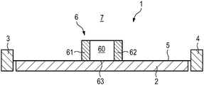
- FIG. 1 is a schematic and highly simplified sectional view in the transverse direction of a body floor structure according to a first embodiment of the invention.
- FIG. 2 is a schematic and highly simplified sectional view in the transverse direction of a body floor structure according to a second embodiment of the invention.
- a body floor structure 1 is intended for a battery electric vehicle or a hybrid vehicle having a traction battery 2 .
- the body floor structure 1 has first and second longitudinal members 3 and 4 that extend substantially parallel to one another in the vehicle longitudinal direction (that is to say into the plane of the drawing).
- the body floor structure 1 also has a floor panel 5 that extends between the two longitudinal members 3 , 4 .
- the traction battery 2 is arranged on a lower side of the floor panel 5 and also extends between the two longitudinal members 3 , 4 .
- the body floor structure 1 has a central tunnel 6 that also extends in the vehicle longitudinal direction.
- the central tunnel 6 serves, under stability aspects, for load dissipation in the event of a frontal impact of the motor vehicle and thereby improves the properties of the motor vehicle in a crash situation.
- the central tunnel 6 has a cavity 60 that is configured to be open in the direction of a vehicle interior 7 . This achieves a situation in which the cavity 60 is accessible from above, that is to say from the vehicle interior 7 . Accordingly, additional components of the motor vehicle, such as, electronic components, can be received in the cavity 60 of the central tunnel 6 .
- the accessibility of the cavity 60 of the central tunnel 6 from above and from the vehicle interior 7 enables equipment components to be mounted within the cavity 60 in a very simple manner and without, for instance, prior laborious demounting of the traction battery 2 being necessary.
- the cavity 60 that opens up and toward the vehicle interior can be used easily as an installation space for components of the vehicle, such as electronic components, even though the traction battery 2 arranged below the floor panel 5 . This results in package advantages.
- the cavity 60 of the central tunnel 6 is laterally delimited by a first and second central tunnel walls 61 and 62 that extend in the longitudinal direction of the body floor structure 1 .
- the first and second central tunnel walls 61 and 62 are flat profiles of substantially I-shaped cross section and are fastened upright on an upper side of the floor panel 5 .
- the central tunnel 6 has a bottom 63 that is formed by a portion of the floor panel 5 that extends between the two central tunnel walls 61 , 62 .
- the two central tunnel walls 61 , 62 configured as flat profiles can be fastened on the upper side of the floor panel 5 , for example, in an integrally bonded manner, such as by welding or adhesive bonding, or with the aid of suitable fasteners (e. g. screws, bolts, rivets, clips or the like).
- suitable fasteners e. g. screws, bolts, rivets, clips or the like.
- FIG. 2 illustrates a second embodiment of a body floor structure 1 for a motor vehicle having a traction battery 2 .
- the body floor structure 1 again has first and second longitudinal members 3 and 4 that extend substantially parallel to one another in the vehicle longitudinal direction, and a floor panel 5 spans between the two longitudinal members 3 , 4 .
- the traction battery 2 is arranged on a lower side of the floor panel 5 and extends between the two longitudinal members 3 , 4 .
- the body floor structure 1 further has a central tunnel 6 ′ with a cavity 60 ′ that is configured open in the direction of the vehicle interior 7 .
- the cavity 60 ′ of the central tunnel 6 ′ is accessible from above and from the vehicle interior 7 .
- This measure again achieves a situation in which additional equipment components of the motor vehicle, such as electronic equipment components, can be accommodated in the cavity 60 ′ of the central tunnel 6 ′, thereby resulting in corresponding package advantages.
- the cavity 60 ′ of the central tunnel 6 ′ is accessible from above from the vehicle interior 7 , mounting of the components in the cavity 60 ′ can occur in a very simple manner without prior demounting of the traction battery 2 being necessary. It is thus possible, in spite of the traction battery 2 arranged below the floor panel 5 , to use the upwardly open cavity 60 ′ of the central tunnel 6 ′ as an installation space for components of the motor vehicle.
- the central tunnel 6 ′ in this embodiment is a one-piece profiled body having a substantially U-shaped cross section and comprised of two central tunnel walls 61 ′, 62 ′ extending in the vehicle longitudinal direction and a bottom 63 ′ extending between the two central tunnel walls 61 ′, 62 ′.
- the central tunnel 6 ′ that is designed as a profiled body can be fastened on the upper side of the floor panel 5 , for example, in an integrally bonded manner, in particular by welding or adhesive bonding, or with the aid of suitable fasteners (e. g. screws, bolts, rivets, clips or the like).
Landscapes
- Engineering & Computer Science (AREA)
- Transportation (AREA)
- Mechanical Engineering (AREA)
- Chemical & Material Sciences (AREA)
- Combustion & Propulsion (AREA)
- Sustainable Development (AREA)
- Life Sciences & Earth Sciences (AREA)
- Sustainable Energy (AREA)
- Power Engineering (AREA)
- Chemical Kinetics & Catalysis (AREA)
- Electrochemistry (AREA)
- General Chemical & Material Sciences (AREA)
- Aviation & Aerospace Engineering (AREA)
- Body Structure For Vehicles (AREA)
- Arrangement Or Mounting Of Propulsion Units For Vehicles (AREA)
Abstract
Description
Claims (5)
Applications Claiming Priority (2)
| Application Number | Priority Date | Filing Date | Title |
|---|---|---|---|
| DE102018114097.5A DE102018114097B4 (en) | 2018-06-13 | 2018-06-13 | Body floor structure for a motor vehicle with a traction battery |
| DE102018114097.5 | 2018-06-13 |
Publications (2)
| Publication Number | Publication Date |
|---|---|
| US20190381878A1 US20190381878A1 (en) | 2019-12-19 |
| US11059363B2 true US11059363B2 (en) | 2021-07-13 |
Family
ID=68724362
Family Applications (1)
| Application Number | Title | Priority Date | Filing Date |
|---|---|---|---|
| US16/432,151 Active US11059363B2 (en) | 2018-06-13 | 2019-06-05 | Body floor structure for a motor vehicle having a traction battery |
Country Status (5)
| Country | Link |
|---|---|
| US (1) | US11059363B2 (en) |
| KR (1) | KR102283924B1 (en) |
| CN (1) | CN110588311A (en) |
| DE (1) | DE102018114097B4 (en) |
| FR (1) | FR3082462B1 (en) |
Cited By (2)
| Publication number | Priority date | Publication date | Assignee | Title |
|---|---|---|---|---|
| US20220305895A1 (en) * | 2021-03-24 | 2022-09-29 | Ford Global Technologies, Llc | Load transferring battery cell arrangement for traction battery pack |
| US20230044178A1 (en) * | 2021-08-03 | 2023-02-09 | Ford Global Technologies, Llc | Battery pack support assembly for electric vehicle |
Citations (12)
| Publication number | Priority date | Publication date | Assignee | Title |
|---|---|---|---|---|
| US5501289A (en) * | 1993-01-22 | 1996-03-26 | Nissan Motor Co., Ltd. | Floor structure of electric vehicle |
| US20090021052A1 (en) * | 2007-07-17 | 2009-01-22 | Honda Motor Co., Ltd. | Sub-frame structure |
| DE102009006990A1 (en) | 2009-01-31 | 2010-08-05 | Audi Ag | Body base structure for motor vehicle e.g. hybrid vehicle, has U-shaped channel part that together with longitudinal supports and base and mounting plate encloses battery module in vehicle channel that accommodates battery module |
| US20100213741A1 (en) * | 2009-02-24 | 2010-08-26 | Honda Motor Co., Ltd. | Vehicle body floor structure |
| KR20110081607A (en) | 2010-01-08 | 2011-07-14 | (주)브이이엔에스 | car |
| FR2955077A1 (en) | 2010-01-12 | 2011-07-15 | Peugeot Citroen Automobiles Sa | Motor vehicle i.e. car, has reinforcement element placed at side of longitudinal tunnel that is utilized for placing battery, where another side of longitudinal tunnel is equipped with access unit for accessing battery |
| US20120248822A1 (en) * | 2011-03-30 | 2012-10-04 | GM Global Technology Operations LLC | Floor structure of a motor vehicle body |
| DE102012203882A1 (en) | 2012-03-13 | 2013-09-19 | Bayerische Motoren Werke Aktiengesellschaft | Autobody for motor vehicle has floor structure in area of passenger compartment, which extends at center in vehicle longitudinal direction seen in vehicle transverse direction |
| US20130313860A1 (en) * | 2011-02-03 | 2013-11-28 | Teijin Limited | Vehicle Floor Structure |
| DE102013016824A1 (en) | 2013-10-10 | 2015-04-16 | Daimler Ag | Vehicle with at least one battery |
| KR101565980B1 (en) | 2014-05-14 | 2015-11-05 | 주식회사 신영 | Floor panel assembly for electric vehicle |
| DE102016204223A1 (en) | 2016-03-15 | 2017-09-21 | Bayerische Motoren Werke Aktiengesellschaft | motor vehicle |
Family Cites Families (7)
| Publication number | Priority date | Publication date | Assignee | Title |
|---|---|---|---|---|
| FR2896756B1 (en) * | 2006-02-01 | 2009-12-11 | Plastic Omnium Cie | FLOOR, FLOOR AND ELECTRICAL CONDUCTOR ASSEMBLY, AND MOTOR VEHICLE ASSEMBLY METHOD |
| ATE526190T1 (en) * | 2008-12-18 | 2011-10-15 | Ferrari Spa | METHOD OF MOUNTING AN ELECTRICAL BATTERY NEAR THE BOTTOM OF THE VEHICLE AND HYBRID POWER VEHICLE |
| EP2402191B1 (en) * | 2009-02-24 | 2016-09-28 | Nissan Motor Co., Ltd. | Battery installation structure |
| US8479858B2 (en) * | 2009-12-03 | 2013-07-09 | Mazda Motor Corporation | Battery arrangement structure of vehicle |
| DE102011115763A1 (en) * | 2011-10-12 | 2013-04-18 | Volkswagen Aktiengesellschaft | Body structure for an electrically driven passenger vehicle |
| DE102012203892A1 (en) * | 2012-03-13 | 2013-09-19 | Bayerische Motoren Werke Aktiengesellschaft | Motor vehicle, particularly passenger motor vehicle, has energy storage that is centrally attached to lower side of floor structure, where energy storage is supporting autobody component and comprises supporting housing |
| FR2994554B1 (en) * | 2012-08-20 | 2014-08-08 | Renault Sa | "BODY STRUCTURE ASSEMBLY OF A MOTOR VEHICLE HAVING A FLAT FRONT FLOOR" |
-
2018
- 2018-06-13 DE DE102018114097.5A patent/DE102018114097B4/en active Active
-
2019
- 2019-05-07 CN CN201910374583.7A patent/CN110588311A/en active Pending
- 2019-05-21 FR FR1905331A patent/FR3082462B1/en active Active
- 2019-06-05 US US16/432,151 patent/US11059363B2/en active Active
- 2019-06-10 KR KR1020190067710A patent/KR102283924B1/en active Active
Patent Citations (12)
| Publication number | Priority date | Publication date | Assignee | Title |
|---|---|---|---|---|
| US5501289A (en) * | 1993-01-22 | 1996-03-26 | Nissan Motor Co., Ltd. | Floor structure of electric vehicle |
| US20090021052A1 (en) * | 2007-07-17 | 2009-01-22 | Honda Motor Co., Ltd. | Sub-frame structure |
| DE102009006990A1 (en) | 2009-01-31 | 2010-08-05 | Audi Ag | Body base structure for motor vehicle e.g. hybrid vehicle, has U-shaped channel part that together with longitudinal supports and base and mounting plate encloses battery module in vehicle channel that accommodates battery module |
| US20100213741A1 (en) * | 2009-02-24 | 2010-08-26 | Honda Motor Co., Ltd. | Vehicle body floor structure |
| KR20110081607A (en) | 2010-01-08 | 2011-07-14 | (주)브이이엔에스 | car |
| FR2955077A1 (en) | 2010-01-12 | 2011-07-15 | Peugeot Citroen Automobiles Sa | Motor vehicle i.e. car, has reinforcement element placed at side of longitudinal tunnel that is utilized for placing battery, where another side of longitudinal tunnel is equipped with access unit for accessing battery |
| US20130313860A1 (en) * | 2011-02-03 | 2013-11-28 | Teijin Limited | Vehicle Floor Structure |
| US20120248822A1 (en) * | 2011-03-30 | 2012-10-04 | GM Global Technology Operations LLC | Floor structure of a motor vehicle body |
| DE102012203882A1 (en) | 2012-03-13 | 2013-09-19 | Bayerische Motoren Werke Aktiengesellschaft | Autobody for motor vehicle has floor structure in area of passenger compartment, which extends at center in vehicle longitudinal direction seen in vehicle transverse direction |
| DE102013016824A1 (en) | 2013-10-10 | 2015-04-16 | Daimler Ag | Vehicle with at least one battery |
| KR101565980B1 (en) | 2014-05-14 | 2015-11-05 | 주식회사 신영 | Floor panel assembly for electric vehicle |
| DE102016204223A1 (en) | 2016-03-15 | 2017-09-21 | Bayerische Motoren Werke Aktiengesellschaft | motor vehicle |
Non-Patent Citations (3)
| Title |
|---|
| German Search Report dated Mar. 29, 2019. |
| Korean Examination Report dated Aug. 20, 2020. |
| Korean Second Notice of Preliminary Rejection dated Apr. 8, 2021. |
Cited By (4)
| Publication number | Priority date | Publication date | Assignee | Title |
|---|---|---|---|---|
| US20220305895A1 (en) * | 2021-03-24 | 2022-09-29 | Ford Global Technologies, Llc | Load transferring battery cell arrangement for traction battery pack |
| US11993140B2 (en) * | 2021-03-24 | 2024-05-28 | Ford Global Technologies, Llc | Load transferring battery cell arrangement for traction battery pack |
| US20230044178A1 (en) * | 2021-08-03 | 2023-02-09 | Ford Global Technologies, Llc | Battery pack support assembly for electric vehicle |
| US11840135B2 (en) * | 2021-08-03 | 2023-12-12 | Ford Global Technologies, Llc | Battery pack support assembly for electric vehicle |
Also Published As
| Publication number | Publication date |
|---|---|
| DE102018114097B4 (en) | 2023-11-16 |
| CN110588311A (en) | 2019-12-20 |
| KR20190141085A (en) | 2019-12-23 |
| FR3082462A1 (en) | 2019-12-20 |
| FR3082462B1 (en) | 2023-08-18 |
| US20190381878A1 (en) | 2019-12-19 |
| KR102283924B1 (en) | 2021-08-02 |
| DE102018114097A1 (en) | 2019-12-19 |
Similar Documents
| Publication | Publication Date | Title |
|---|---|---|
| US10632827B2 (en) | Vehicle lower portion structure | |
| CN114174103B (en) | Accumulator-base assembly for a motor vehicle | |
| US11318992B2 (en) | Vehicle lower structure | |
| US9937780B2 (en) | Front-drive electric vehicle | |
| CN102729791B (en) | For the battery fastening structure of battery-driven car | |
| JP6035926B2 (en) | Fixed structure for on-board equipment | |
| US12403757B2 (en) | Battery pack support device for vehicle | |
| US8622161B2 (en) | Installation structure for electrical equipment in rear vehicle body | |
| US20110266838A1 (en) | Floor structure of a motor vehicle body | |
| EP3045335A1 (en) | Service hole cover and vehicle unit mounting structure | |
| JP2017132450A (en) | Structure for mounting battery and spare tire | |
| US10829157B2 (en) | Vehicle body structure | |
| CN111697172B (en) | Battery tray, power battery package and vehicle | |
| KR20180132801A (en) | Underbody arrangement of rechargeable hybrid vehicle | |
| US20220161680A1 (en) | Device for installing traction batteries, a system and a vehicle | |
| KR20130125815A (en) | Structure for front section of vehicle body | |
| US11059363B2 (en) | Body floor structure for a motor vehicle having a traction battery | |
| US20170210314A1 (en) | Vehicle | |
| KR102105843B1 (en) | Monuting unit of battery-pack for electirc vehicle | |
| US20130333967A1 (en) | Device for fastening a battery module to a bodyshell of a motor vehicle | |
| US12534136B2 (en) | Method for producing a body for a motor vehicle, and body for a motor vehicle | |
| US8919484B2 (en) | Drive arrangement for automobile | |
| CN204586750U (en) | The mounting structure of on-vehicle battery | |
| US12304293B2 (en) | Method for mounting an energy store on a body of a vehicle, and vehicle | |
| CN111697173B (en) | Battery tray, power battery package and vehicle |
Legal Events
| Date | Code | Title | Description |
|---|---|---|---|
| AS | Assignment |
Owner name: DR. ING. H.C. F. PORCHE AKTIENGESELLSCHAFT, GERMAN Free format text: ASSIGNMENT OF ASSIGNORS INTEREST;ASSIGNORS:KOBER, PASCAL;KIELWEIN, STEFFEN;REEL/FRAME:049379/0142 Effective date: 20190604 Owner name: DR. ING. H.C. F. PORCHE AKTIENGESELLSCHAFT, GERMANY Free format text: ASSIGNMENT OF ASSIGNORS INTEREST;ASSIGNORS:KOBER, PASCAL;KIELWEIN, STEFFEN;REEL/FRAME:049379/0142 Effective date: 20190604 |
|
| FEPP | Fee payment procedure |
Free format text: ENTITY STATUS SET TO UNDISCOUNTED (ORIGINAL EVENT CODE: BIG.); ENTITY STATUS OF PATENT OWNER: LARGE ENTITY |
|
| STPP | Information on status: patent application and granting procedure in general |
Free format text: APPLICATION DISPATCHED FROM PREEXAM, NOT YET DOCKETED |
|
| STPP | Information on status: patent application and granting procedure in general |
Free format text: NON FINAL ACTION MAILED |
|
| STPP | Information on status: patent application and granting procedure in general |
Free format text: RESPONSE AFTER FINAL ACTION FORWARDED TO EXAMINER |
|
| STPP | Information on status: patent application and granting procedure in general |
Free format text: NOTICE OF ALLOWANCE MAILED -- APPLICATION RECEIVED IN OFFICE OF PUBLICATIONS |
|
| STPP | Information on status: patent application and granting procedure in general |
Free format text: AWAITING TC RESP., ISSUE FEE NOT PAID |
|
| STPP | Information on status: patent application and granting procedure in general |
Free format text: NOTICE OF ALLOWANCE MAILED -- APPLICATION RECEIVED IN OFFICE OF PUBLICATIONS |
|
| STPP | Information on status: patent application and granting procedure in general |
Free format text: PUBLICATIONS -- ISSUE FEE PAYMENT RECEIVED |
|
| STPP | Information on status: patent application and granting procedure in general |
Free format text: PUBLICATIONS -- ISSUE FEE PAYMENT VERIFIED |
|
| STCF | Information on status: patent grant |
Free format text: PATENTED CASE |
|
| MAFP | Maintenance fee payment |
Free format text: PAYMENT OF MAINTENANCE FEE, 4TH YEAR, LARGE ENTITY (ORIGINAL EVENT CODE: M1551); ENTITY STATUS OF PATENT OWNER: LARGE ENTITY Year of fee payment: 4 |