KR20190141085A - Body floor structure for a motor vehicle having a traction battery - Google Patents
Body floor structure for a motor vehicle having a traction battery Download PDFInfo
- Publication number
- KR20190141085A KR20190141085A KR1020190067710A KR20190067710A KR20190141085A KR 20190141085 A KR20190141085 A KR 20190141085A KR 1020190067710 A KR1020190067710 A KR 1020190067710A KR 20190067710 A KR20190067710 A KR 20190067710A KR 20190141085 A KR20190141085 A KR 20190141085A
- Authority
- KR
- South Korea
- Prior art keywords
- floor structure
- central tunnel
- vehicle
- traction battery
- tunnel
- Prior art date
Links
Images

Classifications
-
- B—PERFORMING OPERATIONS; TRANSPORTING
- B60—VEHICLES IN GENERAL
- B60K—ARRANGEMENT OR MOUNTING OF PROPULSION UNITS OR OF TRANSMISSIONS IN VEHICLES; ARRANGEMENT OR MOUNTING OF PLURAL DIVERSE PRIME-MOVERS IN VEHICLES; AUXILIARY DRIVES FOR VEHICLES; INSTRUMENTATION OR DASHBOARDS FOR VEHICLES; ARRANGEMENTS IN CONNECTION WITH COOLING, AIR INTAKE, GAS EXHAUST OR FUEL SUPPLY OF PROPULSION UNITS IN VEHICLES
- B60K1/00—Arrangement or mounting of electrical propulsion units
- B60K1/04—Arrangement or mounting of electrical propulsion units of the electric storage means for propulsion
-
- B—PERFORMING OPERATIONS; TRANSPORTING
- B60—VEHICLES IN GENERAL
- B60L—PROPULSION OF ELECTRICALLY-PROPELLED VEHICLES; SUPPLYING ELECTRIC POWER FOR AUXILIARY EQUIPMENT OF ELECTRICALLY-PROPELLED VEHICLES; ELECTRODYNAMIC BRAKE SYSTEMS FOR VEHICLES IN GENERAL; MAGNETIC SUSPENSION OR LEVITATION FOR VEHICLES; MONITORING OPERATING VARIABLES OF ELECTRICALLY-PROPELLED VEHICLES; ELECTRIC SAFETY DEVICES FOR ELECTRICALLY-PROPELLED VEHICLES
- B60L50/00—Electric propulsion with power supplied within the vehicle
- B60L50/50—Electric propulsion with power supplied within the vehicle using propulsion power supplied by batteries or fuel cells
- B60L50/60—Electric propulsion with power supplied within the vehicle using propulsion power supplied by batteries or fuel cells using power supplied by batteries
- B60L50/66—Arrangements of batteries
-
- B—PERFORMING OPERATIONS; TRANSPORTING
- B62—LAND VEHICLES FOR TRAVELLING OTHERWISE THAN ON RAILS
- B62D—MOTOR VEHICLES; TRAILERS
- B62D21/00—Understructures, i.e. chassis frame on which a vehicle body may be mounted
- B62D21/02—Understructures, i.e. chassis frame on which a vehicle body may be mounted comprising longitudinally or transversely arranged frame members
-
- B—PERFORMING OPERATIONS; TRANSPORTING
- B62—LAND VEHICLES FOR TRAVELLING OTHERWISE THAN ON RAILS
- B62D—MOTOR VEHICLES; TRAILERS
- B62D25/00—Superstructure or monocoque structure sub-units; Parts or details thereof not otherwise provided for
- B62D25/20—Floors or bottom sub-units
-
- B—PERFORMING OPERATIONS; TRANSPORTING
- B62—LAND VEHICLES FOR TRAVELLING OTHERWISE THAN ON RAILS
- B62D—MOTOR VEHICLES; TRAILERS
- B62D25/00—Superstructure or monocoque structure sub-units; Parts or details thereof not otherwise provided for
- B62D25/20—Floors or bottom sub-units
- B62D25/2009—Floors or bottom sub-units in connection with other superstructure subunits
-
- H01M2/1083—
-
- H—ELECTRICITY
- H01—ELECTRIC ELEMENTS
- H01M—PROCESSES OR MEANS, e.g. BATTERIES, FOR THE DIRECT CONVERSION OF CHEMICAL ENERGY INTO ELECTRICAL ENERGY
- H01M50/00—Constructional details or processes of manufacture of the non-active parts of electrochemical cells other than fuel cells, e.g. hybrid cells
- H01M50/20—Mountings; Secondary casings or frames; Racks, modules or packs; Suspension devices; Shock absorbers; Transport or carrying devices; Holders
- H01M50/249—Mountings; Secondary casings or frames; Racks, modules or packs; Suspension devices; Shock absorbers; Transport or carrying devices; Holders specially adapted for aircraft or vehicles, e.g. cars or trains
-
- B—PERFORMING OPERATIONS; TRANSPORTING
- B60—VEHICLES IN GENERAL
- B60K—ARRANGEMENT OR MOUNTING OF PROPULSION UNITS OR OF TRANSMISSIONS IN VEHICLES; ARRANGEMENT OR MOUNTING OF PLURAL DIVERSE PRIME-MOVERS IN VEHICLES; AUXILIARY DRIVES FOR VEHICLES; INSTRUMENTATION OR DASHBOARDS FOR VEHICLES; ARRANGEMENTS IN CONNECTION WITH COOLING, AIR INTAKE, GAS EXHAUST OR FUEL SUPPLY OF PROPULSION UNITS IN VEHICLES
- B60K1/00—Arrangement or mounting of electrical propulsion units
- B60K1/04—Arrangement or mounting of electrical propulsion units of the electric storage means for propulsion
- B60K2001/0405—Arrangement or mounting of electrical propulsion units of the electric storage means for propulsion characterised by their position
- B60K2001/0438—Arrangement under the floor
-
- B—PERFORMING OPERATIONS; TRANSPORTING
- B60—VEHICLES IN GENERAL
- B60K—ARRANGEMENT OR MOUNTING OF PROPULSION UNITS OR OF TRANSMISSIONS IN VEHICLES; ARRANGEMENT OR MOUNTING OF PLURAL DIVERSE PRIME-MOVERS IN VEHICLES; AUXILIARY DRIVES FOR VEHICLES; INSTRUMENTATION OR DASHBOARDS FOR VEHICLES; ARRANGEMENTS IN CONNECTION WITH COOLING, AIR INTAKE, GAS EXHAUST OR FUEL SUPPLY OF PROPULSION UNITS IN VEHICLES
- B60K1/00—Arrangement or mounting of electrical propulsion units
- B60K1/04—Arrangement or mounting of electrical propulsion units of the electric storage means for propulsion
- B60K2001/0455—Removal or replacement of the energy storages
- B60K2001/0472—Removal or replacement of the energy storages from below
-
- B—PERFORMING OPERATIONS; TRANSPORTING
- B60—VEHICLES IN GENERAL
- B60Y—INDEXING SCHEME RELATING TO ASPECTS CROSS-CUTTING VEHICLE TECHNOLOGY
- B60Y2306/00—Other features of vehicle sub-units
- B60Y2306/01—Reducing damages in case of crash, e.g. by improving battery protection
-
- H—ELECTRICITY
- H01—ELECTRIC ELEMENTS
- H01M—PROCESSES OR MEANS, e.g. BATTERIES, FOR THE DIRECT CONVERSION OF CHEMICAL ENERGY INTO ELECTRICAL ENERGY
- H01M2220/00—Batteries for particular applications
- H01M2220/20—Batteries in motive systems, e.g. vehicle, ship, plane
-
- Y—GENERAL TAGGING OF NEW TECHNOLOGICAL DEVELOPMENTS; GENERAL TAGGING OF CROSS-SECTIONAL TECHNOLOGIES SPANNING OVER SEVERAL SECTIONS OF THE IPC; TECHNICAL SUBJECTS COVERED BY FORMER USPC CROSS-REFERENCE ART COLLECTIONS [XRACs] AND DIGESTS
- Y02—TECHNOLOGIES OR APPLICATIONS FOR MITIGATION OR ADAPTATION AGAINST CLIMATE CHANGE
- Y02E—REDUCTION OF GREENHOUSE GAS [GHG] EMISSIONS, RELATED TO ENERGY GENERATION, TRANSMISSION OR DISTRIBUTION
- Y02E60/00—Enabling technologies; Technologies with a potential or indirect contribution to GHG emissions mitigation
- Y02E60/10—Energy storage using batteries
-
- Y—GENERAL TAGGING OF NEW TECHNOLOGICAL DEVELOPMENTS; GENERAL TAGGING OF CROSS-SECTIONAL TECHNOLOGIES SPANNING OVER SEVERAL SECTIONS OF THE IPC; TECHNICAL SUBJECTS COVERED BY FORMER USPC CROSS-REFERENCE ART COLLECTIONS [XRACs] AND DIGESTS
- Y02—TECHNOLOGIES OR APPLICATIONS FOR MITIGATION OR ADAPTATION AGAINST CLIMATE CHANGE
- Y02T—CLIMATE CHANGE MITIGATION TECHNOLOGIES RELATED TO TRANSPORTATION
- Y02T10/00—Road transport of goods or passengers
- Y02T10/60—Other road transportation technologies with climate change mitigation effect
- Y02T10/70—Energy storage systems for electromobility, e.g. batteries
Abstract
Description
본 발명은, 트랙션 배터리를 구비한 자동차를 위한 차체 바닥 구조에 관한 것으로, 상기 차체 바닥 구조는, 차량 종방향으로 연장되는 제1 종방향 부재 및 제2 종방향 부재; 상기 두 종방향 부재 사이에 걸쳐 있는 바닥 패널; 및 차량 종방향으로 연장되며, 자동차의 구성 부품을 수용하도록 구성된 공동을 구비한 중앙 터널을; 포함하며, 트랙션 배터리는 차체 바닥 구조의 하측에 배치된다.The present invention relates to a vehicle body floor structure for an automobile having a traction battery, the vehicle body structure comprising: a first longitudinal member and a second longitudinal member extending in the vehicle longitudinal direction; A bottom panel spanning between the two longitudinal members; And a central tunnel extending in the vehicle longitudinal direction and having a cavity configured to receive component parts of the vehicle; The traction battery is disposed below the bodywork floor structure.
자동차의 개발에 있어서, 대안적인 구동 컨셉이 점점 더 중요한 역할을 하고 있다. 종종 배터리 전기 자동차로도 지칭되고, 구동 장치로서 적어도 하나의 전기 기계를 구비하는 순수 전기 구동식 자동차, 또는 내연 기관 외에도 적어도 하나의 전기 기계를 구비한 하이브리드 차량에는 트랙션 배터리가 장착되어 전기 기계에 전기 에너지를 공급한다. 트랙션 배터리를 위해 상이한 장착 위치들을 고려할 수 있다. 가능한 장착 위치들 중 하나는 차체 바닥 구조의 하측에 위치한다.In the development of automobiles, alternative drive concepts play an increasingly important role. Often referred to as a battery electric vehicle, a purely electric drive vehicle having at least one electric machine as a driving device, or a hybrid vehicle having at least one electric machine in addition to an internal combustion engine, is equipped with a traction battery to provide electrical power to the electric machine. Supply energy. Different mounting positions may be considered for the traction battery. One of the possible mounting positions is located under the bodywork floor structure.
구동 장치로서 내연기관을 갖는 자동차는 일반적으로 차량 종방향으로 연장되는 중앙 터널을 구비한다. 이 중앙 터널은 컨셉상, 정면 충돌 시 자동차에 작용하는 하중의 일부를 소산시킬 수 있도록 설계되기 때문에, 자동차의 충돌 안전에 기여한다. 아울러, 이와 같은 중앙 터널은 예를 들어 자동차의 배기가스 시스템 또는 변속기의 부품과 같은 자동차의 상이한 구성 부품들을 위한 설치 공간을 제공한다. 종래 자동차의 중앙 터널은 하향 개방되도록 설계된 공동을 구비한다. 예를 들어, 중앙 터널은 역전된 U자형 단면을 가짐으로써 하향 개방된 공동을 얻을 수 있다. 따라서, 중앙 터널 내에 수용될 구성 부품은 아래로부터 중앙 터널 내에 장착되며, 자동차의 외부 영역에 위치한다.An automobile having an internal combustion engine as a drive device generally has a central tunnel extending in the vehicle longitudinal direction. This central tunnel is conceptually designed to dissipate some of the load on the car during a frontal impact, contributing to the car's crash safety. In addition, such a central tunnel provides installation space for different component parts of the motor vehicle, for example parts of the motor vehicle exhaust system or transmission. The central tunnel of a conventional motor vehicle has a cavity designed to open downward. For example, the central tunnel can have a downwardly open cavity by having an inverted U-shaped cross section. Thus, the components to be accommodated in the central tunnel are mounted in the central tunnel from below and are located in the outer region of the motor vehicle.
DE 10 2009 006 990 A1에는, 트랙션 배터리를 구비한 자동차를 위한 차체 바닥 구조가 개시되어 있고, 여기서 차체 바닥 구조는 역전된 U자형 단면 및 하향 개방 공동을 갖는 중앙 터널을 구비한다. 이 공동은 트랙션 배터리를 수용하기 위해 사용된다.DE 10 2009 006 990 A1 discloses a body bottom structure for a motor vehicle with a traction battery, wherein the body bottom structure has a central tunnel with an inverted U-shaped cross section and a downward opening cavity. This cavity is used to receive the traction battery.
차량 종방향으로 연장되는 제1 종방향 부재 및 제2 종방향 부재 사이의 차체 바닥 구조의 하측에 트랙션 배터리를 배치하는 것은 많은 이점을 제공하는 것으로 나타났다. 충돌 거동을 개선하는 것 외에도, 차체 바닥 구조의 하측에 트랙션 배터리를 배치하면 차량 무게 중심이 하강하게 되는데, 이는 특히 자동차의 주행 다이내믹 특성에 긍정적인 영향을 미칠 수 있다. 그러나, 중앙 터널의 공동이 하향 개방되도록 설계되기 때문에, 이 공동은 차체 바닥 구조의 하측에 배치된 트랙션 배터리에 의해 차단되고, 그에 따라 구성 부품은 트랙션 배터리가 먼저 제거되지 않고서는 중앙 터널의 공동 내에 수용될 수 없다. 예를 들어 구성 부품 중 하나가 결함이 있는 경우, 트랙션 배터리를 복잡하게 제거한 후에만 중앙 터널의 공동에 아래로부터 접근 가능하기 때문에, 이는 자동차의 구성 부품을 수용하기 위한 중앙 터널의 유용성을 굉장히 제한한다.Placing the traction battery under the vehicle body structure between the first longitudinal member and the second longitudinal member extending in the vehicle longitudinal direction has been shown to provide many advantages. In addition to improving crash behavior, the placement of the traction battery on the underside of the vehicle floor structure also lowers the vehicle's center of gravity, which can have a particularly positive effect on the driving dynamics of the vehicle. However, since the cavity of the central tunnel is designed to open downward, this cavity is blocked by a traction battery disposed underneath the bodywork floor structure, so that the components are in the cavity of the central tunnel without first removing the traction battery. It cannot be accepted. For example, if one of the components is defective, the cavity of the central tunnel can only be accessed from below after complex removal of the traction battery, which greatly limits the usefulness of the central tunnel for accommodating the components of the vehicle. .
본 발명의 과제는, 도입부에 명시된 유형의 트랙션 배터리를 구비한 자동차를 위한 차체 바닥 구조로서, 트랙션 배터리가 차체 바닥 구조 아래에 배치될 때 중앙 터널의 공동의 유용성을 효과적으로 개선하는 차체 바닥 구조를 제공하는 데에 있다.SUMMARY OF THE INVENTION An object of the present invention is to provide a body floor structure for an automobile having a traction battery of the type specified in the introduction, which effectively improves the usefulness of the cavity of the central tunnel when the traction battery is disposed below the body floor structure. It's there.
상기 과제는 청구항 제1항의 특징부의 특징들을 갖는 해당 유형의 차체 바닥 구조에 의해 해결된다. 종속항들은 본 발명의 유리한 개선에 관한 것이다.The problem is solved by a body bottom structure of the type having the features of the features of
본 발명에 따른 차체 바닥 구조는 중앙 터널의 공동이 차량 내부의 방향으로 개방되도록 설계된다는 특징을 갖는다. 중앙 터널의 공동이 차량 내부의 방향으로 개방되도록 설계되어 차량 내부에서 위로부터 접근 가능하기 때문에, 공동 내에 구성 부품을 장착하는 작업이, 예를 들어 트랙션 배터리를 먼저 제거할 필요 없이 매우 간단한 방식으로 수행될 수 있다. 따라서, 트랙션 배터리가 차체 바닥 구조 아래에 배치되더라도 이제, 상향 개방되도록 설계된 중앙 터널의 공동을, 예를 들어 전자 구성 부품과 같은 자동차의 구성 부품을 수용하기 위한 설치 공간으로서 사용할 수 있다. 이로써 상당한 패키지 관련 이점이 얻어진다.The body floor structure according to the invention is characterized in that the cavity of the central tunnel is designed to open in the direction of the interior of the vehicle. Since the cavity of the central tunnel is designed to open in the direction of the interior of the vehicle and is accessible from above from within the vehicle, mounting the components in the cavity is carried out in a very simple manner, for example without having to remove the traction battery first. Can be. Thus, even if the traction battery is disposed under the body floor structure, the cavity of the central tunnel designed to open upwards can now be used as an installation space for accommodating the components of a vehicle, for example electronic components. This yields significant package related advantages.
중앙 터널은 바람직하게는 실질적으로 U자형 단면을 가질 수 있다.The central tunnel may preferably have a substantially U-shaped cross section.
한 유리한 구현예에서 중앙 터널은, 공동을 측방향으로 제한하기 위해 차체 바닥 구조의 종방향으로 연장되는 제1 중앙 터널 벽 및 제2 중앙 터널 벽을 포함하며, 저면을 구비할 수 있다. 제1 중앙 터널 벽 및 제2 중앙 터널 벽은 바람직하게는 바닥 패널의 상측에 직립 고정되는, 특히 실질적으로 I자형 단면을 갖는 편평한 프로파일로 설계될 수 있다. 2개의 편평한 프로파일은 예를 들어 재료 결합 방식으로, 특히 용접이나 접착 결합에 의해, 또는 적절한 고정 수단의 도움으로, 바닥 패널의 상측에 고정될 수 있다.In one advantageous embodiment the central tunnel includes a first central tunnel wall and a second central tunnel wall extending longitudinally of the bodywork floor structure to laterally confine the cavity and may have a bottom surface. The first center tunnel wall and the second center tunnel wall can preferably be designed in a flat profile, in particular having a substantially I-shaped cross section, which is fixed upright on the upper side of the floor panel. The two flat profiles can be fixed on the upper side of the floor panel, for example in a material bonding manner, in particular by welding or adhesive bonding, or with the aid of suitable fastening means.
특히 유리한 한 구현예에서, 중앙 터널의 저면은 바닥 패널에서 2개의 중앙 터널 벽 사이에 연장되는 부분에 의해 형성될 수 있다. 그러므로, 본 구현예에서는 저면이 바닥 패널에서 2개의 중앙 터널 벽 사이의 부분에 의해 형성되기 때문에, 중앙 터널은 추가 저면을 구비할 필요가 없다. 추가 저면의 생략을 통해 특히 중량 이점이 얻어진다.In one particularly advantageous embodiment, the bottom of the central tunnel may be formed by a portion extending between two central tunnel walls in the floor panel. Therefore, in this embodiment, the central tunnel does not need to have an additional bottom because the bottom is formed by the portion between the two central tunnel walls in the floor panel. The weight advantage is obtained in particular through the omission of an additional bottom.
한 대안적인 유리한 구현예에서는, 중앙 터널이 2개의 중앙 터널 벽, 및 상기 2개의 중앙 터널 벽 사이에 연장되는 저면을 포함하는, 특히 실질적으로 U자형 단면을 갖는 프로파일 몸체로 설계될 수 있다. 프로파일 몸체는 예를 들어 재료 결합 방식으로, 특히 용접이나 접착 결합에 의해, 또는 적절한 고정 수단의 도움으로, 바닥 패널의 상측에 고정될 수 있다.In an alternative advantageous embodiment, the central tunnel can be designed with a profile body, in particular having a substantially U-shaped cross section, comprising two central tunnel walls and a bottom extending between the two central tunnel walls. The profile body can for example be fixed on the upper side of the floor panel in a material bonding manner, in particular by welding or adhesive bonding, or with the aid of suitable fastening means.
중앙 터널의 제조 및 장착을 간소화하기 위해, 특히 유리한 한 구현예에서, 프로파일 몸체가 일체형으로 형성되는 구성을 제안한다.In order to simplify the manufacture and mounting of the central tunnel, in one particularly advantageous embodiment, a configuration is proposed in which the profile body is integrally formed.
한 바람직한 구현예에서, 트랙션 배터리가 바닥 패널의 하측에 부착되는 구성을 제안한다. 트랙션 배터리는 바람직하게 2개의 종방향 부재 사이에 연장될 수 있다. 트랙션 배터리의 이러한 장착 위치에 의해, 특히 충돌 상황에서 자동차의 개선된 특성이 얻어진다.In one preferred embodiment, a configuration is proposed in which the traction battery is attached to the bottom of the bottom panel. The traction battery can preferably extend between two longitudinal members. This mounting position of the traction battery results in improved characteristics of the motor vehicle, especially in a crash situation.
또 다른 한 양태에 따르면, 본 발명은 차체 바닥 구조 및 상기 차체 바닥 구조의 하측에 부착된 트랙션 배터리를 구비한 자동차에 관한 것이다. 본 발명에 따르면, 자동차는 차체 바닥 구조가 청구항 제1항 내지 제8항 중 어느 한 항에 따라 구성된다는 특징이 있다.According to another aspect, the present invention relates to an automobile having a body bottom structure and a traction battery attached to the underside of the body bottom structure. According to the invention, the motor vehicle is characterized in that the vehicle body floor structure is constructed according to any one of
본 발명의 추가 특징 및 이점은 첨부 도면을 참조한 바람직한 실시예들의 하기 설명에서 명확해질 것이다.Further features and advantages of the present invention will become apparent from the following description of the preferred embodiments with reference to the accompanying drawings.
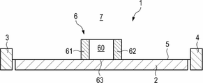
도 1은 본 발명의 제1 실시예에 따라 구현되는 차체 바닥 구조의 고도로 단순화된 개략적인 횡단면도이다.
도 2는 본 발명의 제2 실시예에 따라 구현되는 차체 바닥 구조의 고도로 단순화된 개략적인 횡단면도이다.1 is a highly simplified schematic cross-sectional view of a vehicle body floor structure implemented according to a first embodiment of the invention.
2 is a highly simplified schematic cross-sectional view of a vehicle floor structure implemented according to a second embodiment of the present invention.
도 1을 참조하면, 특히 배터리 전기 차량 또는 하이브리드 차량을 위한 트랙션 배터리(2)를 구비한 자동차를 위해 제공된, 제1 실시예에 따라 구현되는 차체 바닥 구조(1)가, 차량 종방향으로(즉, 도면의 평면 내로) 서로 실질적으로 평행하게 연장되는 제1 종방향 부재(3) 및 제2 종방향 부재(4)를 포함한다. 차체 바닥 구조(1)는 또한 2개의 종방향 부재(3, 4) 사이에 연장되는 바닥 패널(5)을 구비한다. 트랙션 배터리(2)는 바닥 패널(5)의 하측에 배치되며, 마찬가지로 2개의 종방향 부재(3, 4) 사이에 연장된다.With reference to FIG. 1, a
게다가, 차체 바닥 구조(1)는 역시 차량 종방향으로 연장되는 중앙 터널(6)을 구비한다. 이와 같은 중앙 터널(6)은, 안정성 측면에서, 특히 자동차의 정면 충돌의 발생 시 하중을 소산시키는 역할을 하여, 충돌 상황에서의 자동차의 특성을 개선한다.In addition, the
본원에서 중앙 터널(6)은 차량 내부(7)의 방향으로 개방되는 공동(60)을 구비하도록 설계된다. 이를 통해 공동(60)에 위로부터, 즉, 차량 내부(7)로부터 접근할 수 있게 된다. 그로 인해, 예를 들어 전자 구성 부품과 같은 자동차의 추가 구성 부품이 중앙 터널(6)의 공동(60) 내에 수용될 수 있는 가능성을 만든다. 차량 내부(7)에서 위로부터 중앙 터널(6)의 공동(60)에 접근 가능하기 때문에, 공동(60) 내의 구성 부품의 장착은, 예를 들어 트랙션 배터리(2)를 번거롭게 미리 제거하지 않고도 매우 간단한 방식으로 수행될 수 있다. 따라서, 트랙션 배터리(2)가 바닥 패널(5) 아래에 배치되더라도, 여기서 차량 내부(7)의 방향으로 상향 개방되는 공동(60)을, 예를 들어 전자 구성 부품과 같은 자동차의 구성 부품을 위한 설치 공간으로서 사용할 수 있다. 이로써 패키지 관련 이점이 얻어진다.The
도 1에 도시된 실시예에서, 중앙 터널(6)의 공동(60)은 차체 바닥 구조(1)의 종방향으로 연장되는 제1 중앙 터널 벽(61) 및 제2 중앙 터널 벽(62)에 의해 측방향으로 제한된다. 제1 중앙 터널 벽(61) 및 제2 중앙 터널 벽(62)은 여기서 바닥 패널(5)의 상측에 직립 고정된, 특히 실질적으로 I자형 단면을 갖는 편평한 프로파일로 설계된다. 아울러, 중앙 터널(6)은, 바닥 패널(5)에서 2개의 중앙 터널 벽(61, 62) 사이에 연장되는 부분에 의해 형성되는 저면(63)을 구비한다. 편평한 프로파일로 구성된 2개의 중앙 터널 벽(61, 62)은 예를 들어 재료 결합 방식으로, 특히 용접이나 접착 결합에 의해, 또는 적절한 고정 수단의 도움으로, 바닥 패널(5)의 상측에 고정될 수 있다.In the embodiment shown in FIG. 1, the
도 2를 참조하여, 트랙션 배터리(2)를 구비한 자동차를 위한 차체 바닥 구조(1)의 제2 실시예가 이하에 보다 상세히 설명될 것이다. 기본 구조 설계는 제1 실시예의 기본 구조 설계에 상응한다.With reference to FIG. 2, a second embodiment of a
차체 바닥 구조(1)는 다시, 차량 종방향으로 서로 실질적으로 평행하게 연장되는 제1 종방향 부재(3) 및 제2 종방향 부재(4)를 구비한다. 또한, 상기 2개의 종방향 부재(3, 4) 사이에 걸쳐 있는 바닥 패널(5)이 제공된다. 트랙션 배터리(2)는 바닥 패널(5)의 하측에 배치되며, 마찬가지로 2개의 종방향 부재(3, 4) 사이에 연장된다.The vehicle
차체 바닥 구조(1)는 역시 차량 내부(7)의 방향으로 개방되는 공동(60')을 구비하도록 설계된 중앙 터널(6')을 추가로 구비한다. 그러므로, 앞서 제1 실시예에서와 같이, 중앙 터널(6')의 공동(60')은 위로부터, 즉, 차량 내부(7)로부터 접근 가능하다. 이러한 조치를 통해서도 마찬가지로, 예를 들어 전자 구성 부품과 같은 자동차의 추가 구성 부품이 중앙 터널(6')의 공동(60') 내에 수용될 수 있음으로써, 상응하는 패키지 관련 이점을 얻을 수 있게 된다. 차량 내부(7)에서 위로부터 중앙 터널(6')의 공동(60')에 접근 가능하기 때문에, 공동(60') 내에 구성 부품을 장착하는 작업은 트랙션 배터리(2)를 먼저 제거할 필요 없이 매우 간단한 방식으로 수행될 수 있다. 따라서, 트랙션 배터리(2)가 바닥 패널(5) 아래에 배치되더라도, 상향 개방되도록 설계된 중앙 터널(6')의 공동(60')을 자동차의 구성 부품을 위한 설치 공간으로서 사용할 수 있다.The
중앙 터널(6)이 2개의 중앙 터널 벽(61, 62)과; 바닥 패널(5)에서 상기 2개의 중앙 터널 벽(61, 62) 사이에 연장되는 부분;에 의해 형성되었던 제1 실시예와 달리, 본 실시예에서는 중앙 터널(6')이, 차량 종방향으로 연장되는 2개의 중앙 터널 벽(61', 62') 및 상기 2개의 중앙 터널 벽(61', 62') 사이에 연장되는 저면(63')을 포함하는, 실질적으로 U자형 단면을 가지며 바람직하게는 일체형인 프로파일 몸체로 설계된다. 여기서, 프로파일 몸체로 설계된 중앙 터널(6')은 예를 들어 재료 결합 방식으로, 특히 용접이나 접착 결합에 의해, 또는 적절한 고정 수단의 도움으로, 바닥 패널(5)의 상측에 고정될 수 있다.The
Claims (9)
- 차량 종방향으로 연장되는 제1 종방향 부재(3) 및 제2 종방향 부재(4);
- 상기 두 종방향 부재(3, 4) 사이에 걸쳐 있는 바닥 패널(5); 및
- 차량 종방향으로 연장되며, 자동차의 구성 부품을 수용하도록 구성된 공동(60, 60')을 구비한 중앙 터널(6, 6');을 포함하되,
상기 트랙션 배터리(2)는 차체 바닥 구조(1)의 하측에 배치되는, 차체 바닥 구조(1)에 있어서,
중앙 터널(6, 6')의 공동(60, 60')이 차량 내부(7)의 방향으로 개방되도록 설계되는 것을 특징으로 하는, 차체 바닥 구조(1).As a bodywork floor structure 1 for an automobile with a traction battery 2,
A first longitudinal member 3 and a second longitudinal member 4 extending in the vehicle longitudinal direction;
A bottom panel 5 spanning between the two longitudinal members 3, 4; And
A central tunnel 6, 6 ′ extending in the vehicle longitudinal direction and having cavities 60, 60 ′ configured to receive component parts of the motor vehicle;
In the bodywork floor structure 1, the traction battery 2 is disposed below the bodywork floor structure 1,
Body floor structure (1), characterized in that the cavity (60, 60 ') of the central tunnel (6, 6') is designed to open in the direction of the vehicle interior (7).
중앙 터널(6, 6')은 실질적으로 U자형 단면을 갖는 것을 특징으로 하는, 차체 바닥 구조(1).The method of claim 1,
Body tunnel structure (1), characterized in that the central tunnel (6, 6 ') has a substantially U-shaped cross section.
중앙 터널(6, 6')은 공동(60)을 측방향으로 제한하기 위해 차체 바닥 구조(1)의 종방향으로 연장되는 제1 중앙 터널 벽(61, 61') 및 제2 중앙 터널 벽(62, 62')을 포함하며, 저면(63, 63')을 구비하는 것을 특징으로 하는, 차체 바닥 구조(1).The method according to claim 1 or 2,
The central tunnels 6, 6 ′ are provided with a first central tunnel wall 61, 61 ′ and a second central tunnel wall extending longitudinally of the body floor structure 1 to restrict the cavity 60 laterally. 62, 62 '), characterized in that it has a bottom surface (63, 63').
제1 중앙 터널 벽(61) 및 제2 중앙 터널 벽(62)은 바닥 패널(5)의 상측에 직립 고정된 편평한 프로파일로 설계되는 것을 특징으로 하는, 차체 바닥 구조(1).The method of claim 3,
The body floor structure (1), characterized in that the first center tunnel wall (61) and the second center tunnel wall (62) are designed in a flat profile upright fixed on the upper side of the bottom panel (5).
중앙 터널(6)의 저면(63)은, 바닥 패널(5)에서 2개의 중앙 터널 벽(61, 62) 사이에 연장되는 부분에 의해 형성되는 것을 특징으로 하는, 차체 바닥 구조(1).The method according to claim 3 or 4,
The bottom surface (63) of the center tunnel (6) is characterized in that it is formed by a portion extending between two center tunnel walls (61, 62) in the bottom panel (5).
중앙 터널(6')은 2개의 중앙 터널 벽(61', 62'), 및 상기 2개의 중앙 터널 벽(61', 62') 사이에 연장되는 저면(63')을 포함하는 프로파일 몸체로 설계되는 것을 특징으로 하는, 차체 바닥 구조(1).The method of claim 3,
The central tunnel 6 'is designed as a profile body comprising two central tunnel walls 61' and 62 'and a bottom surface 63' extending between the two central tunnel walls 61 'and 62'. Body structure, characterized in that the floor structure (1).
상기 프로파일 몸체는 일체형으로 형성되는 것을 특징으로 하는, 차체 바닥 구조(1).The method of claim 6,
The body bottom structure (1), characterized in that the profile body is formed in one piece.
트랙션 배터리(2)는 바닥 패널(5)의 하측에 부착되는 것을 특징으로 하는, 차체 바닥 구조(1).The method according to any one of claims 1 to 7,
The traction battery (2) is attached to the underside of the bottom panel (5), bodywork floor structure (1).
차체 바닥 구조(1)는 제1항 내지 제8항 중 어느 한 항에 따라 구성되는 것을 특징으로 하는, 자동차.In a motor vehicle having a body bottom structure (1) and a traction battery (2) attached to a lower side of the body bottom structure (1),
An automobile body, characterized in that the body floor structure (1) is constructed according to any one of the preceding claims.
Applications Claiming Priority (2)
| Application Number | Priority Date | Filing Date | Title |
|---|---|---|---|
| DE102018114097.5A DE102018114097B4 (en) | 2018-06-13 | 2018-06-13 | Body floor structure for a motor vehicle with a traction battery |
| DE102018114097.5 | 2018-06-13 |
Publications (2)
| Publication Number | Publication Date |
|---|---|
| KR20190141085A true KR20190141085A (en) | 2019-12-23 |
| KR102283924B1 KR102283924B1 (en) | 2021-08-02 |
Family
ID=68724362
Family Applications (1)
| Application Number | Title | Priority Date | Filing Date |
|---|---|---|---|
| KR1020190067710A KR102283924B1 (en) | 2018-06-13 | 2019-06-10 | Body floor structure for a motor vehicle having a traction battery |
Country Status (5)
| Country | Link |
|---|---|
| US (1) | US11059363B2 (en) |
| KR (1) | KR102283924B1 (en) |
| CN (1) | CN110588311A (en) |
| DE (1) | DE102018114097B4 (en) |
| FR (1) | FR3082462B1 (en) |
Families Citing this family (2)
| Publication number | Priority date | Publication date | Assignee | Title |
|---|---|---|---|---|
| US20220305895A1 (en) * | 2021-03-24 | 2022-09-29 | Ford Global Technologies, Llc | Load transferring battery cell arrangement for traction battery pack |
| US11840135B2 (en) * | 2021-08-03 | 2023-12-12 | Ford Global Technologies, Llc | Battery pack support assembly for electric vehicle |
Citations (4)
| Publication number | Priority date | Publication date | Assignee | Title |
|---|---|---|---|---|
| KR20110081607A (en) * | 2010-01-08 | 2011-07-14 | (주)브이이엔에스 | Automobile |
| US20120248822A1 (en) * | 2011-03-30 | 2012-10-04 | GM Global Technology Operations LLC | Floor structure of a motor vehicle body |
| DE102013016824A1 (en) * | 2013-10-10 | 2015-04-16 | Daimler Ag | Vehicle with at least one battery |
| KR101565980B1 (en) * | 2014-05-14 | 2015-11-05 | 주식회사 신영 | Floor panel assembly for electric vehicle |
Family Cites Families (15)
| Publication number | Priority date | Publication date | Assignee | Title |
|---|---|---|---|---|
| US5501289A (en) * | 1993-01-22 | 1996-03-26 | Nissan Motor Co., Ltd. | Floor structure of electric vehicle |
| FR2896756B1 (en) * | 2006-02-01 | 2009-12-11 | Plastic Omnium Cie | FLOOR, FLOOR AND ELECTRICAL CONDUCTOR ASSEMBLY, AND MOTOR VEHICLE ASSEMBLY METHOD |
| JP4308285B2 (en) * | 2007-07-17 | 2009-08-05 | 本田技研工業株式会社 | Subframe structure |
| EP2199133B1 (en) * | 2008-12-18 | 2011-09-28 | FERRARI S.p.A. | Method for arranging an electric accumulating device in proximity of a vehicle floor and hybrid propulsion vehicle |
| DE102009006990A1 (en) | 2009-01-31 | 2010-08-05 | Audi Ag | Body base structure for motor vehicle e.g. hybrid vehicle, has U-shaped channel part that together with longitudinal supports and base and mounting plate encloses battery module in vehicle channel that accommodates battery module |
| JP4856731B2 (en) * | 2009-02-24 | 2012-01-18 | 本田技研工業株式会社 | Body floor structure |
| EP2402191B1 (en) * | 2009-02-24 | 2016-09-28 | Nissan Motor Co., Ltd. | Battery installation structure |
| US8479858B2 (en) * | 2009-12-03 | 2013-07-09 | Mazda Motor Corporation | Battery arrangement structure of vehicle |
| FR2955077B1 (en) | 2010-01-12 | 2012-04-27 | Peugeot Citroen Automobiles Sa | VEHICLE HAVING A FLOOR SUITABLE FOR RECEIVING A BATTERY AND A REINFORCING BEAM |
| WO2012105389A1 (en) * | 2011-02-03 | 2012-08-09 | 帝人株式会社 | Vehicle floor structure |
| DE102011115763A1 (en) * | 2011-10-12 | 2013-04-18 | Volkswagen Aktiengesellschaft | Body structure for an electrically driven passenger vehicle |
| DE102012203882B4 (en) | 2012-03-13 | 2021-03-25 | Bayerische Motoren Werke Aktiengesellschaft | Body of a motor vehicle |
| DE102012203892A1 (en) * | 2012-03-13 | 2013-09-19 | Bayerische Motoren Werke Aktiengesellschaft | Motor vehicle, particularly passenger motor vehicle, has energy storage that is centrally attached to lower side of floor structure, where energy storage is supporting autobody component and comprises supporting housing |
| FR2994554B1 (en) * | 2012-08-20 | 2014-08-08 | Renault Sa | "BODY STRUCTURE ASSEMBLY OF A MOTOR VEHICLE HAVING A FLAT FRONT FLOOR" |
| DE102016204223A1 (en) | 2016-03-15 | 2017-09-21 | Bayerische Motoren Werke Aktiengesellschaft | motor vehicle |
-
2018
- 2018-06-13 DE DE102018114097.5A patent/DE102018114097B4/en active Active
-
2019
- 2019-05-07 CN CN201910374583.7A patent/CN110588311A/en active Pending
- 2019-05-21 FR FR1905331A patent/FR3082462B1/en active Active
- 2019-06-05 US US16/432,151 patent/US11059363B2/en active Active
- 2019-06-10 KR KR1020190067710A patent/KR102283924B1/en active IP Right Grant
Patent Citations (4)
| Publication number | Priority date | Publication date | Assignee | Title |
|---|---|---|---|---|
| KR20110081607A (en) * | 2010-01-08 | 2011-07-14 | (주)브이이엔에스 | Automobile |
| US20120248822A1 (en) * | 2011-03-30 | 2012-10-04 | GM Global Technology Operations LLC | Floor structure of a motor vehicle body |
| DE102013016824A1 (en) * | 2013-10-10 | 2015-04-16 | Daimler Ag | Vehicle with at least one battery |
| KR101565980B1 (en) * | 2014-05-14 | 2015-11-05 | 주식회사 신영 | Floor panel assembly for electric vehicle |
Also Published As
| Publication number | Publication date |
|---|---|
| KR102283924B1 (en) | 2021-08-02 |
| US11059363B2 (en) | 2021-07-13 |
| DE102018114097B4 (en) | 2023-11-16 |
| FR3082462A1 (en) | 2019-12-20 |
| DE102018114097A1 (en) | 2019-12-19 |
| FR3082462B1 (en) | 2023-08-18 |
| CN110588311A (en) | 2019-12-20 |
| US20190381878A1 (en) | 2019-12-19 |
Similar Documents
| Publication | Publication Date | Title |
|---|---|---|
| US10632827B2 (en) | Vehicle lower portion structure | |
| KR101613014B1 (en) | Supporting frame for a motor vehicle | |
| US11220298B2 (en) | Lower vehicle-body structure of electric vehicle | |
| CN109204551B (en) | Vehicle body front structure | |
| JP6118381B2 (en) | Automotive battery | |
| CN107128373B (en) | Motor vehicle with at least partial electric drive | |
| US20110266838A1 (en) | Floor structure of a motor vehicle body | |
| CN102530082B (en) | The body frame structure for automotive of automobile, rear cycle frame structure and vehicle body | |
| CN109204496B (en) | Vehicle body structure and vehicle | |
| JP6035926B2 (en) | Fixed structure for on-board equipment | |
| US20230095674A1 (en) | Vehicle-body structure with improved passenger comfort and vehicle-body stiffness | |
| JP2017132450A (en) | Structure for mounting battery and spare tire | |
| CN111465521A (en) | Motor vehicle with drive battery | |
| KR101138509B1 (en) | Vehicle body | |
| KR20180132801A (en) | Underbody arrangement of rechargeable hybrid vehicle | |
| KR102283924B1 (en) | Body floor structure for a motor vehicle having a traction battery | |
| CN110901362A (en) | Vehicle lower structure | |
| CN111697172B (en) | Battery tray, power battery package and vehicle | |
| JP2014019260A (en) | Positioning pin bracket for battery pack | |
| US20230101665A1 (en) | Vehicle-body structure with a battery cover for improved aerodynamic performance | |
| US20150075891A1 (en) | Electricity-storage device arrangement structure of vehicle | |
| KR20220063505A (en) | Structure for fastening battery to vehicle | |
| US8919484B2 (en) | Drive arrangement for automobile | |
| US20230286588A1 (en) | Method for Producing a Body for a Motor Vehicle, and Body for a Motor Vehicle | |
| CN204586750U (en) | The mounting structure of on-vehicle battery |
Legal Events
| Date | Code | Title | Description |
|---|---|---|---|
| A201 | Request for examination | ||
| E902 | Notification of reason for refusal | ||
| E902 | Notification of reason for refusal | ||
| E701 | Decision to grant or registration of patent right | ||
| GRNT | Written decision to grant |