US11057560B2 - Image pickup apparatus, image pickup method, and recording medium - Google Patents
Image pickup apparatus, image pickup method, and recording medium Download PDFInfo
- Publication number
- US11057560B2 US11057560B2 US16/786,388 US202016786388A US11057560B2 US 11057560 B2 US11057560 B2 US 11057560B2 US 202016786388 A US202016786388 A US 202016786388A US 11057560 B2 US11057560 B2 US 11057560B2
- Authority
- US
- United States
- Prior art keywords
- image
- images
- composite image
- image pick
- focus
- Prior art date
- Legal status (The legal status is an assumption and is not a legal conclusion. Google has not performed a legal analysis and makes no representation as to the accuracy of the status listed.)
- Expired - Fee Related
Links
Images


Classifications
-
- H04N5/23229—
-
- H—ELECTRICITY
- H04—ELECTRIC COMMUNICATION TECHNIQUE
- H04N—PICTORIAL COMMUNICATION, e.g. TELEVISION
- H04N23/00—Cameras or camera modules comprising electronic image sensors; Control thereof
- H04N23/60—Control of cameras or camera modules
- H04N23/64—Computer-aided capture of images, e.g. transfer from script file into camera, check of taken image quality, advice or proposal for image composition or decision on when to take image
-
- H—ELECTRICITY
- H04—ELECTRIC COMMUNICATION TECHNIQUE
- H04N—PICTORIAL COMMUNICATION, e.g. TELEVISION
- H04N23/00—Cameras or camera modules comprising electronic image sensors; Control thereof
- H04N23/60—Control of cameras or camera modules
- H04N23/63—Control of cameras or camera modules by using electronic viewfinders
- H04N23/633—Control of cameras or camera modules by using electronic viewfinders for displaying additional information relating to control or operation of the camera
-
- H—ELECTRICITY
- H04—ELECTRIC COMMUNICATION TECHNIQUE
- H04N—PICTORIAL COMMUNICATION, e.g. TELEVISION
- H04N23/00—Cameras or camera modules comprising electronic image sensors; Control thereof
- H04N23/80—Camera processing pipelines; Components thereof
-
- H—ELECTRICITY
- H04—ELECTRIC COMMUNICATION TECHNIQUE
- H04N—PICTORIAL COMMUNICATION, e.g. TELEVISION
- H04N23/00—Cameras or camera modules comprising electronic image sensors; Control thereof
- H04N23/95—Computational photography systems, e.g. light-field imaging systems
- H04N23/958—Computational photography systems, e.g. light-field imaging systems for extended depth of field imaging
- H04N23/959—Computational photography systems, e.g. light-field imaging systems for extended depth of field imaging by adjusting depth of field during image capture, e.g. maximising or setting range based on scene characteristics
-
- H04N5/23293—
Definitions
- the aspect of the embodiments relates to an image pickup apparatus that picks up a plurality of images with different in-focus positions.
- H10-290389 discusses a so-called depth composition technology in which a plurality of images with different in-focus positions is picked up, only in-focus areas are extracted from each of the images to combine the images into one image, and thereby a composite image in which all imaging areas are in focus is generated.
- an apparatus includes an image pick-up unit configured to pick up a plurality of first images and at least one second image, at least a part of angles of view of the plurality of first images overlapping each other, a combining unit configured to extract a focused part from each of the plurality of first images to generate a first composite image, and a display configured to display the first composite image, wherein the combining unit further extracts focused parts from the first composite image and the at least one second image to generate a second composite image.
- FIG. 1 is a block diagram illustrating a hardware configuration of a digital camera according to an exemplary embodiment of the disclosure.
- FIG. 2 is a flowchart for describing generation of a composite image according to the exemplary embodiment of the disclosure.
- FIG. 3 is a diagram for describing an example of presentation of additional image pick-up according to the exemplary embodiment of the disclosure.
- FIG. 4 is a flowchart for describing storage of the image pick-up information according to the exemplary embodiment of the disclosure.
- FIG. 5 is a flowchart for describing the setting of an image pick-up method for additional image pick-up according to the exemplary embodiment of the disclosure.
- FIGS. 6A to 6C are diagrams for describing image pick-up according to the exemplary embodiment of the disclosure.
- FIGS. 7A to 7C are diagrams for describing additional image pick-up according to the exemplary embodiment of the disclosure.
- FIG. 1 is a block diagram illustrating a hardware configuration of a digital camera according to the present exemplary embodiment.
- the digital camera 100 can pick up still images, record information about in-focus positions, and calculate contrast values and combine images as well.
- the digital camera 100 can enlarge or reduce picked-up and stored images, or images input from the outside.
- a control unit 101 is a signal processor, such as a central processing unit (CPU) or a micro-processing unit (MPU), and controls each part of the digital camera 100 while reading out in advance a program stored in a read-only memory (ROM) 105 , which will be described below.
- the control unit 101 issues instructions on a start and an end of image pick-up to an image pick-up unit 104 , which will be described below.
- the control unit 101 issues an instruction on image processing to an image processing unit 107 , which will be described below, on the basis of a program stored in the ROM 105 .
- An instruction from a user is input to the digital camera 100 by an operation unit 110 , which will be described below, and reaches each part of the digital camera 100 via the control unit 101 .
- a drive unit 102 includes a motor and the like and causes an optical system 103 , which will be described below, to mechanically operate under an instruction of the control unit 101 .
- the drive unit 102 moves a position of a focus lens included in the optical system 103 to adjust an in-focus position of the optical system 103 on the basis of an instruction of the control unit 101 .
- the optical system 103 includes a zoom lens, the focus lens, an aperture, and the like.
- the aperture is a mechanism that adjusts a quantity of transmitted light. An in-focus position can be changed by changing a position of the lens.
- the image pick-up unit 104 is a photoelectric conversion element that photoelectrically converts a signal of incident light into an electrical signal.
- a charge coupled device (CCD) sensor, a complementary metal-oxide semiconductor (CMOS) sensor, or the like can be applied to the image pick-up unit 104 .
- the image pick-up unit 104 has a moving image capturing mode in which a plurality of images that are consecutive in time can be picked up as frames of a moving image.
- the ROM 105 is a non-volatile memory dedicated to readout as a memory medium storing not only operation programs of each block of the digital camera 100 but also parameters for operations of each block and the like.
- a random access memory (RAM) 106 is a rewritable volatile memory used as a transitory storage area of data output in operations of each block of the digital camera 100 .
- An image processing unit 107 performs various kinds of image processing such as white balance adjustment, color interpolation, and filtering on an image output from the image pick-up unit 104 or data of image signals recorded in a built-in memory 109 , which will be described below.
- the image processing unit 107 performs compression processing on data of signals of images picked up by the image pick-up unit 104 in the standard of Joint Photographic Experts Group (JPEG), or the like.
- JPEG Joint Photographic Experts Group
- the image processing unit 107 includes an application-specific integrated circuit (ASIC) in which circuits for specific processing are gathered.
- ASIC application-specific integrated circuit
- the control unit 101 may also perform some or all of the functions of the image processing unit 107 when the control unit 101 performs processing according to a program read out from the ROM 105 . In a case where the control unit 101 performs all of the functions of the image processing unit 107 , the control unit 101 does not need to have the image processing unit 107 as hardware.
- the image processing unit 107 can perform additive combining processing, weighted additive combining processing, and the like.
- the pixel value may be set to a value of each signal of R, G1, and G2, and B of a Bayer array output after automatic white balancing (AWB) is performed, or a value of a luminance signal (luminance value) obtained from a group of signals of R, G1, G2, and B.
- ABB automatic white balancing
- a luminance value may be calculated for each pixel after signals of the Bayer array are interpolated so that the signals of R, G, and B are present in each pixel.
- Alignment processing or the like is performed on a plurality of pieces of image data if necessary and each of associated pixel values is processed according to the formulas described below.
- a display unit 108 is a liquid crystal display, an organic electro-luminescence (EL) display, or the like for displaying an image temporarily stored in the RAM 106 or an image stored in the built-in memory 109 , which will be described below, a setting screen of the digital camera 100 , or the like.
- EL organic electro-luminescence
- the built-in memory 109 is a place in which images picked up by the image pick-up unit 104 or images processed by the image processing unit 107 , information about an in-focus position at the time of image pick-up, and the like are recorded.
- a memory card or the like may be used instead of the built-in memory.
- the operation unit 110 is, for example, a button, a switch, a key, a mode dial or the like attached to the digital camera 100 , a touch panel that is also used as the display unit 108 , or the like. An instruction from a user is delivered to the control unit 101 via the operation unit 110 .
- FIG. 2 is a flowchart for describing generation of a composite image according to the present exemplary embodiment.
- step S 201 the control unit 101 makes a setting for picking up an image on the basis of an instruction from a user.
- the instruction from the user is delivered to the control unit 101 via the operation unit 110 .
- Settings for picking up an image mentioned here include, for example, an in-focus position at which a first image is picked up, an in-focus position movement interval between images when a second image and subsequent images are picked up, the number of images to be picked-up, and the like.
- An example of a user operation includes an operation performed by the user for designating an in-focus position on the touch panel and setting a plurality of in-focus positions at predetermined focus intervals from the in-focus position as a center using the control unit 101 .
- step S 202 the control unit 101 performs control such that the image pick-up unit 104 picks up images at each of the in-focus positions while changing focus of the lenses included in the optical system 103 of the digital camera 100 to each of the in-focus positions set in step S 201 .
- the settings other than the focus of the digital camera 100 are not changed while the images are picked up, the angle of view of the picked-up images slightly is changed when the in-focus positions are varied.
- step S 203 the control unit 101 stores image pick-up information of step S 201 such as the in-focus positions, the in-focus position movement interval, and the number of images to be picked up. Storage of the image pick-up information will be described below in detail.
- step S 204 the image processing unit 107 performs depth composition on the images picked up by the image pick-up unit 104 in step S 202 .
- the control unit 101 calculates an amount of a position shift of two images to be combined. An example of the calculation method will be described below.
- the control unit 101 sets a plurality of blocks in one image. In one embodiment, the control unit 101 sets sizes of the blocks to be equal.
- the control unit 101 sets wider ranges than the blocks at the same positions as each of the set blocks in the other image as search ranges.
- the control unit 101 calculates correspondence points in each of search ranges of the other image, at which the sum of absolute differences (which will be referred to as an SAD below) in luminance from the initially set blocks has a minimum value.
- the control unit 101 calculates a position shift as a vector using the center of the initially set blocks and the above-described correspondence points.
- the control unit 101 may use the sum of squared differences (which will be referred to as an SSD below), a normalized cross correlation (which will be referred to as an NCC below), or the like, in addition to the SAD in the calculation of the above-described correspondence points.
- the control unit 101 calculates a transformation coefficient from the amount of the position shift.
- the transformation coefficient the control unit 101 uses, for example, a projective transformation coefficient.
- a transformation coefficient is not limited to a projective transformation coefficient, and a simplified transformation coefficient only of an affine transformation coefficient or a horizontal/vertical shift may be used.
- the control unit 101 can perform deformation using the formula indicated in the Formula 4 as follows:
- the image processing unit 107 calculates a contrast value of each of aligned images.
- a contrast value I is calculated using a Sobel filter in a matrix L of the luminance Y of 3 ⁇ 3 pixels as indicated in the Formula 6 to the Formula 8 as follows:
- I h ( - 1 0 1 - 2 0 2 - 1 0 1 ) ⁇ L ( Formula ⁇ ⁇ 6 )
- I v ( - 1 - 2 - 1 0 0 0 1 2 1 ) ⁇ L ( Formula ⁇ ⁇ 7 )
- I I h 2 + I v 2 ( Formula ⁇ ⁇ 8 )
- contrast value calculation method is merely an example, and for example, an edge detection filter such as a Laplacian filter or a band-pass filter that allows passage in a predetermined band can also be used as a filter to be used.
- an edge detection filter such as a Laplacian filter or a band-pass filter that allows passage in a predetermined band can also be used as a filter to be used.
- the image processing unit 107 generates a composition map.
- a composition map generation method the image processing unit 107 compares the contrast values of pixels at the same position in each of images, sets a composition ratio of pixels having the highest contrast value to 100%, and sets a composition ratio of pixels at positions other than the same position to 0%. The image processing unit 107 sets such composition ratios for all positions of the images.
- the image processing unit 107 replaces pixels according to the composition map to generate a composite image. If the composition ratio of adjacent pixels calculated as described above is changed from 0% to 100% (or changed from 100% to 0%), unnaturalness stands out at the composition boundaries. For this reason, a filter with a predetermined number of pixels (the number of taps) is applied to the composition map to prevent the composition ratio of the adjacent pixels from abruptly changing.
- step S 205 the display unit 108 displays the composite image generated in step S 204 .
- step S 206 the display unit 108 presents presence or absence of additional image pick-up and methods of additional image pick-up, and prompts the user to make a selection.
- FIG. 3 is a diagram for describing an example of presentation of additional image pick-up according to the present exemplary embodiment.
- the display unit 108 prompts a user to select additional image pick-up by displaying a screen as illustrated in FIG. 3 .
- the display unit 108 displays buttons 301 to 304 together with the composite image displayed in step S 205 .
- the buttons 301 to 304 indicate “additional image pick-up on a close distance side”, “additional image pick-up on an infinite distance side”, “additional image pick-up with interpolation at an in-focus position”, and “no additional image pick-up”, respectively.
- a method for additional image pick-up or no operation of additional image pick-up is selected.
- the display unit 108 may display the buttons 301 to 304 without displaying the composite image in step S 206 .
- the display unit 108 may display buttons of “perform additional image pick-up” and “no additional image pick-up” in advance and display the buttons of “additional image pick-up on a close distance side”, “additional image pick-up on an infinite distance side”, and “additional image pick-up with interpolation at an in-focus position” after the button of “perform additional image pick-up” is selected.
- step S 207 the control unit 101 determines whether to perform additional image pick-up on the basis of an instruction from the user. In a case where no additional image pick-up is performed (NO in step S 207 ), the flow of FIG. 2 ends. In a case where additional image pick-up is performed (YES in step S 207 ), the processing proceeds to step S 208 , and the control unit 101 sets an image pick-up method for additional image pick-up. Details of the setting of the image pick-up method for additional image pick-up will be described below.
- FIG. 4 is a flowchart for describing storage of the image pick-up information according to the present exemplary embodiment.
- step S 401 the control unit 101 determines whether the previous image pick-up in step S 202 is first image pick-up or additional image pick-up. If the previous image pick-up is first image pick-up (NO in step S 401 ), the processing proceeds to step S 402 , the control unit 101 stores the focus interval at the time of the image pick-up, and in step S 403 , the control unit 101 stores the in-focus position on the closest distance side and the in-focus position on the most infinite distance side among in-focus positions of the image pick-up. The processing proceeds to step S 404 , and the control unit 101 stores the number of images to be picked up.
- step S 401 if the previous image pick-up is additional image pick-up in step S 401 (YES in step S 401 ), the processing proceeds to step S 405 .
- step S 405 and step S 406 the control unit 101 determines a method for the previous additional image pick-up.
- step S 405 the control unit 101 determines whether the method for the previous additional image pick-up is addition by interpolation. If the method is addition by interpolation (YES in step S 405 ), the processing proceeds to step S 407 , and if the method is not addition by interpolation (NO in step S 405 ), the processing proceeds to step S 406 .
- step S 406 the control unit 101 further determines whether the method for the previous additional image pick-up is addition from a close distance side.
- step S 406 If the method is addition from a close distance side (YES in step S 406 ), the processing proceeds to step S 408 , and if the method is not addition from a close distance side, that is, if the method is addition from an infinite distance side (NO in step S 406 ), the processing proceeds to step S 409 .
- step S 407 the control unit 101 updates and stores the stored focus interval.
- step S 408 the control unit 101 updates and stores the stored in-focus position on the closest distance side.
- step S 409 the control unit 101 updates and stores the stored in-focus position on the most infinite distance side.
- step S 404 the number of images to be picked up stored by the control unit 101 can be calculated using the number of in-focus positions set later, and at that time, the number of images to be picked up may not be stored in step S 404 .
- FIG. 5 is a flowchart for describing the setting of an image pick-up method for additional image pick-up according to the present exemplary embodiment.
- the control unit 101 determines whether the method for additional image pick-up is addition by interpolation. If the method is addition by interpolation (YES in step S 501 ), the processing proceeds to step S 507 , and if the method is not addition by interpolation (NO in step S 501 ), the processing proceeds to step S 502 .
- step S 507 the control unit 101 sets the focus interval stored in the previous image pick-up to be used as a focus interval of the additional image pick-up.
- step S 508 the control unit 101 determines an in-focus position for a start of the additional image pick-up and a focus moving direction. For example, the control unit 101 determines any of in-focus positions at both ends among added in-focus positions as an in-focus position for a start and determines a focus moving direction accordingly.
- step S 502 the control unit 101 determines whether a method for the additional image pick-up is addition from a close distance side. If the method is addition from a close distance side (YES in step S 502 ), the processing proceeds to step S 503 , and if the method is not addition from a close distance side, that is, if the method is addition from an infinite distance side (NO in step S 502 ), the processing proceeds to step S 505 .
- step S 503 the control unit 101 sets an in-focus position on the closest distance side among in-focus positions at which a start position of the additional image pick-up is added.
- An example of a method of determining the in-focus position on the closest distance side mentioned here will be described.
- the user observes the composite image gives an instruction of the location corresponding to the limit to which a depth of field is to be extended, sets an in-focus position on the closest distance side to the location, and sets the in-focus position as a start position of the additional image pick-up.
- step S 504 the control unit 101 sets a focus moving direction of the additional image pick-up from the close distance side to the infinite distance side.
- step S 509 the control unit 101 sets the stored focus interval as a focus interval for the additional image pick-up. That is, the control unit 101 makes the focus interval of the additional image pick-up equal to the focus interval of the previous image pick-up.
- step S 505 the control unit 101 sets an in-focus position on the most infinite distance side among in-focus positions at which a start position of the additional image pick-up is added. For example, in a similar way, the user observes the composite image, gives an instruction of the location corresponding to the limit to which a depth of field is to be extended, sets an in-focus position on the most infinite distance side to the location, and sets the in-focus position as a start position of the additional image pick-up.
- step S 506 the control unit 101 sets a focus moving direction of the additional image pick-up from the infinite distance side to the close distance side.
- step S 509 the control unit 101 sets the stored focus interval as a focus interval for the additional image pick-up.
- the control unit 101 makes the focus interval of the additional image pick-up equal to the focus interval of the previous image pick-up.
- the focus moving direction may be reversed.
- the focus interval of the additional image pick-up is set to be equal to that of the previous image pick-up here, the configuration is not limited thereto and may be appropriately changed according to a situation. For example, if an object of which perceived resolution is to be particularly improved is in a focus range of additional image pick-up, focus intervals may be set to be narrower.
- step S 208 The setting of the image pick-up method for additional image pick-up of step S 208 is as described above.
- FIGS. 6A to 6C are diagrams for describing image pick-up according to the present exemplary embodiment.
- FIG. 6A illustrates that the digital camera faces three subjects 601 , 602 , and 603 at different distances in the optical axis direction and the display unit 108 displays the subjects 601 , 602 , and 603 .
- FIG. 6B illustrates a state in which the digital camera picks up an image at a plurality of in-focus positions 604 , performs depth composition, and generates a composite image. Since the plurality of in-focus positions 604 is not placed between the subject 601 and the subject 603 , the subject 601 and the subject 603 are blurred in the composite image.
- FIG. 6C illustrates a state in which the digital camera picks up an image at a plurality of in-focus positions, performs depth composition, and generates a composite image. Since distances between the plurality of in-focus positions are longer than each depth of field, out-of-focus ranges 605 are generated. In the composite image, a part of the subject 602 is blurry.
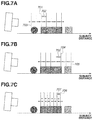
- FIGS. 7A to 7C are diagrams for describing additional image pick-up according to the present exemplary embodiment.
- FIG. 7A illustrates a state of additional image pick-up on a close distance side for obtaining a composite image in which the subject 601 is also in focus.
- the control unit 101 sets an in-focus position for additional image pick-up at a position on a closer distance side than an in-focus position 701 .
- the control unit 101 sets an in-focus position 703 on a closest distance side to the subject and then sets an in-focus position of another operation of additional image pick-up such that the focus interval between the second in-focus position and the in-focus position 701 becomes equal to the previous focus interval 702 .
- FIG. 7B illustrates a state of additional image pick-up on an infinite distance side for obtaining a composite image in which the subject 603 is also in focus.
- the control unit 101 sets an in-focus position for additional image pick-up at a position on an infinite distance side than an in-focus position 401 .
- the control unit 101 sets an in-focus position 705 on a most infinite distance side to the subject and then sets an in-focus position of another operation of additional image pick-up such that the focus interval between the second in-focus position and the in-focus position 705 becomes equal to the previous focus interval 702 .
- FIG. 7C illustrates a state in which the control unit 101 sets a new in-focus position in the middle of the in-focus positions of the previous image pick-up to prevent a blurry part from occurring in the subject 602 .
- a focus interval 707 after the additional image pick-up is half the focus interval before the additional image pick-up.
- the in-focus position of the additionally picked up image is at the center of the in-focus positions of adjacent images among the previously picked-up images.
- a composite image in which both the subject 601 and the subject 603 are in focus can be generated in one operation of additional image pick-up in, for example, the case illustrated in FIG. 6B .
- an intended composite image when an image is picked up for depth composition as described above, even if an unintended composite image is generated, for example, an intended composite image can be obtained by using an image that has already been picked up and performing additional image pick-up, without picking up images again from the beginning.
- image pick-up may be processed by the image pick-up apparatus and the like, and composite processing may be performed using other processing apparatuses such as a personal computer and a server.
- implementation of the exemplary embodiment is not limited to a digital camera.
- the exemplary embodiment may be implemented in a mobile device or the like in which an image sensor is built in or a network camera or the like that can pick up images.
- the aspect of the embodiments can be realized in processing in which a program for realizing one or more functions of the exemplary embodiment described above is supplied to a system or an apparatus via a network or a storage medium and one or more processors of a computer of the system or the apparatus read out and operate the program.
- the aspect of the embodiments can be realized by a circuit that realizes one or more of the functions (e.g., an ASIC).
- an image pick-up apparatus that generates an intended composite image even if an unexpected composite image is generated when depth composition is performed, without picking up images again from the beginning can be provided.
- Embodiment(s) of the disclosure can also be realized by a computer of a system or apparatus that reads out and executes computer executable instructions (e.g., one or more programs) recorded on a storage medium (which may also be referred to more fully as a ‘non-transitory computer-readable storage medium’) to perform the functions of one or more of the above-described embodiment(s) and/or that includes one or more circuits (e.g., application specific integrated circuit (ASIC)) for performing the functions of one or more of the above-described embodiment(s), and by a method performed by the computer of the system or apparatus by, for example, reading out and executing the computer executable instructions from the storage medium to perform the functions of one or more of the above-described embodiment(s) and/or controlling the one or more circuits to perform the functions of one or more of the above-described embodiment(s).
- computer executable instructions e.g., one or more programs
- a storage medium which may also be referred to more fully as a ‘
- the computer may comprise one or more processors (e.g., central processing unit (CPU), micro processing unit (MPU)) and may include a network of separate computers or separate processors to read out and execute the computer executable instructions.
- the computer executable instructions may be provided to the computer, for example, from a network or the storage medium.
- the storage medium may include, for example, one or more of a hard disk, a random-access memory (RAM), a read only memory (ROM), a storage of distributed computing systems, an optical disk (such as a compact disc (CD), digital versatile disc (DVD), or Blu-ray Disc (BD)TM), a flash memory device, a memory card, and the like.
Landscapes
- Engineering & Computer Science (AREA)
- Multimedia (AREA)
- Signal Processing (AREA)
- Computing Systems (AREA)
- Theoretical Computer Science (AREA)
- Studio Devices (AREA)
- Automatic Focus Adjustment (AREA)
Applications Claiming Priority (3)
| Application Number | Priority Date | Filing Date | Title |
|---|---|---|---|
| JP2019026720A JP6828069B2 (ja) | 2019-02-18 | 2019-02-18 | 撮像装置、撮像方法およびプログラム |
| JPJP2019-026720 | 2019-02-18 | ||
| JP2019-026720 | 2019-02-18 |
Publications (2)
| Publication Number | Publication Date |
|---|---|
| US20200267316A1 US20200267316A1 (en) | 2020-08-20 |
| US11057560B2 true US11057560B2 (en) | 2021-07-06 |
Family
ID=72042562
Family Applications (1)
| Application Number | Title | Priority Date | Filing Date |
|---|---|---|---|
| US16/786,388 Expired - Fee Related US11057560B2 (en) | 2019-02-18 | 2020-02-10 | Image pickup apparatus, image pickup method, and recording medium |
Country Status (2)
| Country | Link |
|---|---|
| US (1) | US11057560B2 (ja) |
| JP (1) | JP6828069B2 (ja) |
Families Citing this family (1)
| Publication number | Priority date | Publication date | Assignee | Title |
|---|---|---|---|---|
| EP4138384A3 (en) * | 2021-08-16 | 2023-04-19 | Canon Kabushiki Kaisha | Imaging apparatus, imaging method, and storage medium |
Citations (9)
| Publication number | Priority date | Publication date | Assignee | Title |
|---|---|---|---|---|
| JPH10290389A (ja) | 1997-04-16 | 1998-10-27 | Toyota Motor Corp | マルチフォーカス画像作成方法及び画像作成装置 |
| US20100271498A1 (en) * | 2009-04-22 | 2010-10-28 | Qualcomm Incorporated | System and method to selectively combine video frame image data |
| US20140267833A1 (en) * | 2013-03-12 | 2014-09-18 | Futurewei Technologies, Inc. | Image registration and focus stacking on mobile platforms |
| JP2015127772A (ja) | 2013-12-27 | 2015-07-09 | 株式会社キーエンス | 拡大観察装置、拡大画像観察方法、拡大画像観察プログラム及びコンピュータで読み取り可能な記録媒体 |
| US20160028948A1 (en) * | 2013-04-10 | 2016-01-28 | Sharp Kabushiki Kaisha | Image capturing apparatus |
| US20160191784A1 (en) * | 2013-08-07 | 2016-06-30 | Sharp Kabushiki Kaisha | Imaging device |
| JP2018046543A (ja) | 2016-09-13 | 2018-03-22 | パナソニックIpマネジメント株式会社 | 画像処理装置及び撮像装置 |
| US20180252894A1 (en) * | 2015-09-11 | 2018-09-06 | Heptagon Micro Optics Pte. Ltd. | Imaging devices having autofocus control |
| US10282825B2 (en) * | 2016-09-13 | 2019-05-07 | Panasonic Intellectual Property Management Co., Ltd. | Image processing apparatus and imaging apparatus |
-
2019
- 2019-02-18 JP JP2019026720A patent/JP6828069B2/ja not_active Expired - Fee Related
-
2020
- 2020-02-10 US US16/786,388 patent/US11057560B2/en not_active Expired - Fee Related
Patent Citations (9)
| Publication number | Priority date | Publication date | Assignee | Title |
|---|---|---|---|---|
| JPH10290389A (ja) | 1997-04-16 | 1998-10-27 | Toyota Motor Corp | マルチフォーカス画像作成方法及び画像作成装置 |
| US20100271498A1 (en) * | 2009-04-22 | 2010-10-28 | Qualcomm Incorporated | System and method to selectively combine video frame image data |
| US20140267833A1 (en) * | 2013-03-12 | 2014-09-18 | Futurewei Technologies, Inc. | Image registration and focus stacking on mobile platforms |
| US20160028948A1 (en) * | 2013-04-10 | 2016-01-28 | Sharp Kabushiki Kaisha | Image capturing apparatus |
| US20160191784A1 (en) * | 2013-08-07 | 2016-06-30 | Sharp Kabushiki Kaisha | Imaging device |
| JP2015127772A (ja) | 2013-12-27 | 2015-07-09 | 株式会社キーエンス | 拡大観察装置、拡大画像観察方法、拡大画像観察プログラム及びコンピュータで読み取り可能な記録媒体 |
| US20180252894A1 (en) * | 2015-09-11 | 2018-09-06 | Heptagon Micro Optics Pte. Ltd. | Imaging devices having autofocus control |
| JP2018046543A (ja) | 2016-09-13 | 2018-03-22 | パナソニックIpマネジメント株式会社 | 画像処理装置及び撮像装置 |
| US10282825B2 (en) * | 2016-09-13 | 2019-05-07 | Panasonic Intellectual Property Management Co., Ltd. | Image processing apparatus and imaging apparatus |
Also Published As
| Publication number | Publication date |
|---|---|
| JP2020136866A (ja) | 2020-08-31 |
| JP6828069B2 (ja) | 2021-02-10 |
| US20200267316A1 (en) | 2020-08-20 |
Similar Documents
| Publication | Publication Date | Title |
|---|---|---|
| JP5421829B2 (ja) | 撮像装置 | |
| US8593509B2 (en) | Three-dimensional imaging device and viewpoint image restoration method | |
| CN103098457B (zh) | 立体成像装置和立体成像方法 | |
| US9319599B2 (en) | Image processing apparatus, image processing method, and non-transitory storage medium storing an image processing program | |
| US10652453B2 (en) | Electronic apparatus and control method thereof | |
| US11206348B2 (en) | Image apparatus to generate a combined image, control method for controlling an apparatus to generate a combined image, and storage medium | |
| US11653107B2 (en) | Image pick up apparatus, image pick up method, and storage medium | |
| US11778321B2 (en) | Image capturing apparatus capable of performing omnifocal photographing, method of controlling same, and storage medium | |
| US10419686B2 (en) | Image pickup apparatus and method for controlling the display of through image data based on shutter state | |
| US20190387172A1 (en) | Image capturing apparatus, method of controlling same, and storage medium | |
| US11375110B2 (en) | Image processing apparatus, image pickup apparatus, image processing method, and non-transitory computer-readable storage medium | |
| US11057560B2 (en) | Image pickup apparatus, image pickup method, and recording medium | |
| US11044396B2 (en) | Image processing apparatus for calculating a composite ratio of each area based on a contrast value of images, control method of image processing apparatus, and computer-readable storage medium | |
| JP6476064B2 (ja) | 撮像装置、及び撮像制御方法 | |
| US20230066494A1 (en) | Apparatus to perform alignment to images, image processing method to perform alignment to images, and computer readable non-transitory memory to perform alignment to images | |
| US11206350B2 (en) | Image processing apparatus, image pickup apparatus, image processing method, and storage medium | |
| US12382171B2 (en) | Image capturing apparatus for capturing and compositing images different in in-focus position, control method, and storage medium | |
| US12444031B2 (en) | Image processing apparatus, imaging apparatus, image processing method, and recording medium background | |
| US20250238896A1 (en) | Image processing apparatus, image capturing apparatus, image processing method, and storage medium | |
| JP2014063190A (ja) | 撮像装置 |
Legal Events
| Date | Code | Title | Description |
|---|---|---|---|
| FEPP | Fee payment procedure |
Free format text: ENTITY STATUS SET TO UNDISCOUNTED (ORIGINAL EVENT CODE: BIG.); ENTITY STATUS OF PATENT OWNER: LARGE ENTITY |
|
| AS | Assignment |
Owner name: CANON KABUSHIKI KAISHA, JAPAN Free format text: ASSIGNMENT OF ASSIGNORS INTEREST;ASSIGNOR:TAKECHI, KOKI;REEL/FRAME:053064/0916 Effective date: 20200123 |
|
| STPP | Information on status: patent application and granting procedure in general |
Free format text: DOCKETED NEW CASE - READY FOR EXAMINATION |
|
| STPP | Information on status: patent application and granting procedure in general |
Free format text: NOTICE OF ALLOWANCE MAILED -- APPLICATION RECEIVED IN OFFICE OF PUBLICATIONS |
|
| STPP | Information on status: patent application and granting procedure in general |
Free format text: PUBLICATIONS -- ISSUE FEE PAYMENT RECEIVED |
|
| STPP | Information on status: patent application and granting procedure in general |
Free format text: PUBLICATIONS -- ISSUE FEE PAYMENT VERIFIED Free format text: AWAITING TC RESP, ISSUE FEE PAYMENT VERIFIED |
|
| STPP | Information on status: patent application and granting procedure in general |
Free format text: PUBLICATIONS -- ISSUE FEE PAYMENT VERIFIED |
|
| STCF | Information on status: patent grant |
Free format text: PATENTED CASE |
|
| FEPP | Fee payment procedure |
Free format text: MAINTENANCE FEE REMINDER MAILED (ORIGINAL EVENT CODE: REM.); ENTITY STATUS OF PATENT OWNER: LARGE ENTITY |
|
| LAPS | Lapse for failure to pay maintenance fees |
Free format text: PATENT EXPIRED FOR FAILURE TO PAY MAINTENANCE FEES (ORIGINAL EVENT CODE: EXP.); ENTITY STATUS OF PATENT OWNER: LARGE ENTITY |
|
| STCH | Information on status: patent discontinuation |
Free format text: PATENT EXPIRED DUE TO NONPAYMENT OF MAINTENANCE FEES UNDER 37 CFR 1.362 |
|
| FP | Lapsed due to failure to pay maintenance fee |
Effective date: 20250706 |