US11054865B2 - Hinge module and electronic device - Google Patents
Hinge module and electronic device Download PDFInfo
- Publication number
- US11054865B2 US11054865B2 US16/177,438 US201816177438A US11054865B2 US 11054865 B2 US11054865 B2 US 11054865B2 US 201816177438 A US201816177438 A US 201816177438A US 11054865 B2 US11054865 B2 US 11054865B2
- Authority
- US
- United States
- Prior art keywords
- sliding
- tabs
- brackets
- torque
- pair
- Prior art date
- Legal status (The legal status is an assumption and is not a legal conclusion. Google has not performed a legal analysis and makes no representation as to the accuracy of the status listed.)
- Active
Links
Images


Classifications
-
- G—PHYSICS
- G06—COMPUTING OR CALCULATING; COUNTING
- G06F—ELECTRIC DIGITAL DATA PROCESSING
- G06F1/00—Details not covered by groups G06F3/00 - G06F13/00 and G06F21/00
- G06F1/16—Constructional details or arrangements
- G06F1/1613—Constructional details or arrangements for portable computers
- G06F1/1633—Constructional details or arrangements of portable computers not specific to the type of enclosures covered by groups G06F1/1615 - G06F1/1626
- G06F1/1675—Miscellaneous details related to the relative movement between the different enclosures or enclosure parts
- G06F1/1681—Details related solely to hinges
-
- G—PHYSICS
- G06—COMPUTING OR CALCULATING; COUNTING
- G06F—ELECTRIC DIGITAL DATA PROCESSING
- G06F1/00—Details not covered by groups G06F3/00 - G06F13/00 and G06F21/00
- G06F1/16—Constructional details or arrangements
- G06F1/1613—Constructional details or arrangements for portable computers
- G06F1/1615—Constructional details or arrangements for portable computers with several enclosures having relative motions, each enclosure supporting at least one I/O or computing function
- G06F1/1616—Constructional details or arrangements for portable computers with several enclosures having relative motions, each enclosure supporting at least one I/O or computing function with folding flat displays, e.g. laptop computers or notebooks having a clamshell configuration, with body parts pivoting to an open position around an axis parallel to the plane they define in closed position
- G06F1/1618—Constructional details or arrangements for portable computers with several enclosures having relative motions, each enclosure supporting at least one I/O or computing function with folding flat displays, e.g. laptop computers or notebooks having a clamshell configuration, with body parts pivoting to an open position around an axis parallel to the plane they define in closed position the display being foldable up to the back of the other housing with a single degree of freedom, e.g. by 360° rotation over the axis defined by the rear edge of the base enclosure
-
- G—PHYSICS
- G06—COMPUTING OR CALCULATING; COUNTING
- G06F—ELECTRIC DIGITAL DATA PROCESSING
- G06F1/00—Details not covered by groups G06F3/00 - G06F13/00 and G06F21/00
- G06F1/16—Constructional details or arrangements
- G06F1/1613—Constructional details or arrangements for portable computers
- G06F1/1633—Constructional details or arrangements of portable computers not specific to the type of enclosures covered by groups G06F1/1615 - G06F1/1626
- G06F1/1675—Miscellaneous details related to the relative movement between the different enclosures or enclosure parts
- G06F1/1679—Miscellaneous details related to the relative movement between the different enclosures or enclosure parts for locking or maintaining the movable parts of the enclosure in a fixed position, e.g. latching mechanism at the edge of the display in a laptop or for the screen protective cover of a PDA
-
- H—ELECTRICITY
- H05—ELECTRIC TECHNIQUES NOT OTHERWISE PROVIDED FOR
- H05K—PRINTED CIRCUITS; CASINGS OR CONSTRUCTIONAL DETAILS OF ELECTRIC APPARATUS; MANUFACTURE OF ASSEMBLAGES OF ELECTRICAL COMPONENTS
- H05K5/00—Casings, cabinets or drawers for electric apparatus
- H05K5/0017—Casings, cabinets or drawers for electric apparatus with operator interface units
-
- H—ELECTRICITY
- H05—ELECTRIC TECHNIQUES NOT OTHERWISE PROVIDED FOR
- H05K—PRINTED CIRCUITS; CASINGS OR CONSTRUCTIONAL DETAILS OF ELECTRIC APPARATUS; MANUFACTURE OF ASSEMBLAGES OF ELECTRICAL COMPONENTS
- H05K5/00—Casings, cabinets or drawers for electric apparatus
- H05K5/02—Details
- H05K5/0217—Mechanical details of casings
- H05K5/0226—Hinges
Definitions
- the invention relates to a hinge module, and more particularly to a hinge module and an electronic device applying the hinge module.
- a torque module may be composed of a plurality of shrapnel, pads, screw caps, which are applied additionally. If the structural design is wished not to be unobtrusive or even concealed, it is necessary to preset enough accommodating space for adding or accommodating the torque module. However, this may also enlarge the overall size, which is not only disadvantageous to the overall design, but is not compliant with the market needs that the overall design tends to be light and thin.
- Another method is to generate a second by a valve.
- the flaw of this method is that the torque generated by the valve may not be adjusted.
- the invention provides a hinge module having a new configuration.
- the invention provides an electronic device which it's buttons may be lifted and lowered along with the opening and closing of the casing.
- the invention provides a hinge module, including a pair of brackets, a plurality of tabs, a torque providing assembly, and a plurality of torque adjustment members.
- Each of the brackets has at least one first sliding slot extending along a first direction and a first through hole extending along a second direction, wherein the first direction and the second direction are perpendicular to each other.
- the tabs pass through the corresponding first sliding slots, and each of the tabs has a second sliding slot extending along the second direction.
- the torque providing assembly has a first end and a second end, wherein one of the brackets and one of the tabs are connected to the first end, and the other one of the brackets and the other one of the tabs are connected the second end.
- the torque adjusting member inserts into the corresponding first through holes of the brackets and the corresponding second sliding slots of the tabs.
- An electronic device of the invention includes a first casing, a second casing, the aforementioned hinge modules, a sliding sheet, and a pair of sliding rods, wherein the hinge module is connected between the first casing and the second casing.
- the sliding sheet is disposed corresponding to a keyboard module of the second casing, and is connected to a plurality of buttons of the keyboard module.
- one end of the sliding rod is connected to two of the tabs of the hinge module, and the other end of the sliding rod is connected to opposite two sides of the sliding sheet.
- the torque of the tabs relative to the brackets may be easily adjusted.
- the tabs move on a linear direction, and the sliding rod connected correspondingly between the tabs and the sliding sheet moves along with the tabs and the buttons are thus lifted and lowered during the moving process.
- FIG. 1 is a schematic view of an electronic device of the invention.
- FIG. 2 is a schematic view of a hinge module of FIG. 1 connected to a keyboard module by a sliding assembly.
- FIG. 3 is an exploded schematic view of a hinge module, a sliding assembly, and a keyboard module.
- FIG. 4 is a partial schematic view of another angle of FIG. 2 .
- FIG. 5 is an exploded schematic view of a hinge module illustrated in FIG. 1 .
- FIG. 5A is an enlarged schematic view of a fourth through hole illustrated in FIG. 5 .
- FIG. 6 is a schematic view of a sliding rod.
- FIG. 7 is a schematic view of a sliding sheet.
- FIG. 8 is a schematic view of a hinge module when a first casing is closed relative to a second casing.
- FIG. 9 is a schematic view of a hinge module when a first casing is opened relative to a second casing.
- FIG. 10 is a schematic view of a hinge module when a first casing is fully opened to 180 degrees relative to a second casing.
- FIG. 11 is a schematic view of a hinge module, a sliding assembly, and a keyboard module of FIG. 9 .
- FIG. 12 is a schematic view of a hinge module, a sliding assembly, and a keyboard module of FIG. 8 .
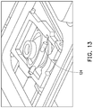
- FIG. 13 is a schematic view of a linkage component disposed on the keyboard to be connected to a sliding sheet.
- FIG. 14 is a schematic view of a hinge module of the second embodiment of the invention.
- FIG. 15 is an exploded schematic view of FIG. 14 .
- FIG. 1 is a schematic view of an electronic device of the invention.
- FIG. 2 is a schematic view of a hinge module of FIG. 1 connected to a keyboard module by a sliding assembly.
- FIG. 3 is an exploded schematic view of a hinge module, a sliding assembly, and a keyboard module, and
- FIG. 4 is a partial schematic view of another angle of FIG. 2 .
- an electronic device 100 is a laptop, including a first casing 110 having a display portion 112 , a second casing 120 having a keyboard module 122 , a hinge module 130 connected between the first casing 110 and the second casing 120 , and a sliding assembly 140 connected between the hinge module 130 and the keyboard module 122 .
- the hinge module 130 connected between the first casing 110 and the second casing 120 may enable the first casing 110 and the second casing 120 to be relatively opened and closed.
- the sliding assembly 140 is disposed corresponding to the keyboard module 122 of the second casing 120 , and is connected to a plurality of buttons 123 of the keyboard module 122 .
- the hinge module 130 provides a torque that the first casing 110 is fixed at a certain angle relative to the second casing 120 , and at the same time, the buttons 123 of the keyboard module 122 are lifted by being driven by the sliding assembly 140 .
- the buttons 123 of the keyboard module 122 are lowered by being driven by the hinge module 130 .
- FIG. 5 is an exploded schematic view of a hinge module illustrated in FIG. 1 .
- the hinge module 130 of this embodiment includes a pair of brackets 131 , 132 , a plurality of tabs 133 , a torque providing assembly, and a plurality of torque adjustment member 134 .
- the torque providing assembly is connected between the two brackets 131 , 132 to provide a first torque to the two brackets 131 , 132 .
- the tabs 133 are connected to two ends of the torque providing assembly, and are disposed by passing through the two brackets 131 , 132 .
- the torque adjustment member 134 is disposed to limit the movement of the plurality of tabs 133 relative to the two brackets 131 , 132 , and adjust a second torque between the plurality of tabs 133 and the two brackets 131 , 132 .
- each of the brackets 131 , 132 has at least one first sliding slot S 1 extending along a first direction X, and a first through hole h 1 extending along a second direction Z, wherein the first direction X and the second direction Z are perpendicular to each other, and the tabs 133 are disposed passing corresponding through the first sliding slot S 1 .
- each of the brackets 131 , 132 may include a bracket body 131 a and a pair of first fixing blocks 131 b .
- the aforementioned first sliding slot S 1 and the first through hole h 1 are disposed in the bracket body 131 a , and the bracket body 131 a may further have a pair of first fixing slots 135 on the opposite sides of the first sliding slot S 1 , wherein the first fixing slots 135 is disposed to accommodate a first fixing block 131 b .
- the bracket body 131 a may have a plurality of locking holes F, and the locking hole F may also be disposed on the first fixing block 131 b . Therefore, by inserting a fixing member 136 , for example, a screw or a screw bolt, into the corresponding locking hole F to combine the bracket body 131 a with the first fixing block 131 b.
- the fixing member 136 may also pass through the rest of locking holes F on the bracket body 131 a , and insert into the first casing 110 or the second casing 120 correspondingly, so that the hinge module 130 is fixed onto the first casing 110 and the second casing 120 .
- the tabs 133 disposed to pass through the corresponding first sliding slot S 1 has the second sliding slots S 2 extending along a second direction Z, wherein an orthographic projection of the first through hole h 1 of the brackets 131 , 132 overlaps with the scope of the second sliding slots S 2 of the tabs 133 .
- the torque adjustment member 134 inserts into the first through hole h 1 of the bracket body 131 a and the second sliding slots S 2 of the tabs 133 correspondingly, so that the tabs 133 may be able to perform linear movement in the first sliding slot S 1 along the first direction X.
- the torque adjustment member 134 may be the same as the fixing member 136 , the screw may be selected, and the insertion degree of the screw may change the second torque of the first sliding slot S 1 relative to the tabs 133 .
- a plurality of storing slots S 3 may be disposed on a surface of a slot wall of the first sliding slot S 1 contacted with the tabs 133 .
- the storing slots S 3 are disposed to accommodate lubricating liquid.
- the lubricating liquid may reduce the friction between the tabs 133 and the slot wall of the first sliding slot S 1 .
- applying the lubricating liquid may be a method of adjusting the second torque.
- the torque providing assembly has a first end and a second end, wherein the bracket 131 and one of the tabs 133 are connected to the first end and the bracket 132 and another one of the tabs 133 are connected to the second end. Therefore, when the two brackets 131 , 132 are opened to each other, a certain angle is fixed by the torque provided by the torque providing assembly. In addition, with the changes of the angle between the two brackets 131 , 132 , the length of the tabs 133 protruding from the first sliding slot S 1 changes accordingly.
- the torque providing assembly includes a plurality of linkage arms 211 , a plurality of fixing shafts 212 , a plurality of sliding axis 213 , and a plurality of shared shafts 214 .
- the linkage arms 211 are mostly in shapes of boomerangs, and each of the linkage arms 211 has a second through hole h 2 , a third through hole h 3 , and a fourth through hole h 4 , wherein the third through hole h 3 is located between the second through hole h 2 disposed between the two ends of the linkage arms 211 and the fourth through hole h 4 , mostly located in the middle of the linkage arms 211 .
- the fixing shaft 212 passes through the second through hole h 2 correspondingly, wherein the second through hole h 2 is a C-axis hole, and two ends of the fixing shaft 212 inserts to the corresponding brackets 131 , 132 , so that the linkage arms 211 are initially rotatably connected to the brackets 131 , 132 .
- each of the first fixing blocks 131 b has a fixing shaft hole 131 c , and the two ends of the fixing shaft 212 inserts into the corresponding fixing shaft hole 131 c , so that the torque providing assembly may be connected to the brackets 131 , 132 in a manner of rotating relative to the bracket body 131 a.
- the sliding axis 213 passes corresponding through the fourth through hole h 4 and a through hole (not illustrated) of the tabs 133 , wherein the fourth through hole h 4 is a scoop-shaped shaft hole (as illustrated in FIG. 5A , FIG. 5A being an enlarged schematic view of a fourth through hole illustrated in FIG. 5 ), and two ends of the sliding axis 213 inserts into the corresponding brackets 131 , 132 , so that the tabs 133 may be fixed to the bracket body 131 a in a manner of linear moving along the first direction X in the first sliding slot S 1 .
- the shared shaft 214 passes through the third through hole h 3 correspondingly, so that all the linkage arms 211 are connected together.
- the scoop-shaped shaft hole (as illustrated in FIG. 5A ) and the sliding axis 213 inserted therein generate the first torque by mutual interference with each other, wherein since the shape of the scoop-shaped shaft hole (as shown in FIG. 5A ) provides a space for deformation, the first torque would not be too big to bring about inconveniences.
- the scoop-shaped shaft hole here indicates a shaft hole having a round hole for the sliding axis 213 to insert, and an opening from one side of the round hole to a long-oval hole connected to the round hole.
- the shape of the opening may not be limited to the shapes illustrated in this embodiment. People skilled in the art in the art may change the shape of the opening based on actual needs.
- the shape of the linkage arms 211 are the same. However, the linkage arms 211 are not symmetrical structures centered on the third through hole h 3 . To achieve force balance, the quantity of the linkage arms 211 may thus be plural.
- the linkage arms 211 are staggered with the shared shaft 214 as a symmetrical centerline. The staggered disposition here is, for example, that the second through hole h 2 of a singular quantity of the linkage arm 211 is disposed on the left side of the shared shaft 214 , and the second through hole h 2 of a plural quantity of the plurality of linkage arms 211 is disposed on the right side of the shared shaft 214 .
- each of the first fixing blocks 131 b has a third sliding slot S 4 .
- the third sliding slot S 4 extends along a third direction Y, and the third direction Y are perpendicular to the second direction Z as well as the first direction X, wherein the two ends of the sliding axis 213 insert into the third sliding slot S 4 correspondingly.
- the third sliding slot S 4 is roughly flat, and the two ends of the sliding axis 213 both have parallel columns 213 a conformed to the third sliding slot S 4 .
- the ends of the sliding axis 213 may only perform linear movement in the third sliding slot S 4 to avoid the occurrence of self-rotation of the sliding axis 213 .
- the end of the sliding axis 213 is circular, while the end of the sliding axis 213 is moving in the third sliding slot S 4 , the self-rotation of the sliding axis 213 may occur.
- the hinge module 130 further includes a torque adjustment ring 137 disposed in the first through hole h 1 , wherein the torque adjustment member 134 passes through the torque adjustment ring 137 correspondingly to insert into the first through hole h 1 of the bracket body 131 a and the second sliding slots S 2 of the tabs 133 to generate the second torque. By the insertion degree of the torque adjustment member 134 , the second torque is adjusted.
- FIG. 6 is a schematic view of a sliding rod
- FIG. 7 is a schematic view of a sliding sheet. Please refer to FIG. 4 , FIG. 6 , and FIG. 7 at the same time.
- the sliding assembly 140 includes a sliding sheet 142 and a pair of sliding rods 144 . One end of the sliding rods 144 is connected to the tabs 133 of the hinge module 130 , and the other end of the sliding rods 144 is connected to the two sides of the sliding sheet 142 .
- the sliding sheet 142 has sliding slots S 5 disposed on two sides.
- the sliding rods 144 have a sliding column 145 , and the sliding column 145 inserts corresponding into the sliding slot S 5 .
- Each of the sliding slots S 5 has two parallel portions ss 1 , ss 3 parallel to the first direction X and staggered from each other on the third direction Y, and a connecting portion ss 2 obliquely connected between the parallel portions ss 1 , ss 3 .
- FIG. 8 is a schematic view of a hinge module when a first casing is closed relative to a second casing.
- FIG. 9 is a schematic view of a hinge module when a first casing is opened relative to a second casing
- FIG. 10 is a schematic view of a hinge module when a first casing is fully opened to 180 degrees relative to a second casing.
- FIG. 11 is a schematic view of a hinge module, a sliding assembly, and a keyboard module of FIG. 9 .
- FIG. 12 is a schematic view of a hinge module, a sliding assembly, and a keyboard module of FIG. 8 .
- FIG. 13 is a schematic view of a linkage component disposed on the keyboard to be connected to a sliding sheet.
- the counterweight of the second casing 120 is heavier than the weight of the first casing 110 . Therefore, when the first casing 110 of the electronic device 100 (as illustrated in FIG. 1 ) is slowly opened from a closed state relative to the second casing 120 (as illustrated in FIG. 1 ), the bracket 132 connected to the second casing 120 (as illustrated in FIG. 1 ) rotates relatively to the brackets 131 connected to the first casing 110 with the shared shaft 214 as a rotation axis.
- the two brackets 131 , 132 and the tabs 133 are connected together by the torque providing assembly.
- the shared shaft 214 is relatively opened as a rotating shaft.
- one end of the linkage arms 211 passes through the second through hole h 2 of the linkage arms 211 by the fixing shaft 212 , and inserts into a fixing shaft hole 131 c of the first fixing block 131 b .
- the other end of the linkage arms 211 passes through the fourth through hole h 4 of the linkage arms 211 and an insertion hole (not illustrated) of the tabs 133 and inserts into the third sliding slot S 4 by the sliding axis 213 .
- the linkage arms 211 rotate with one end connected to the brackets 131 , 132 and the other end rotates with the rotation of the brackets 131 , 132 .
- the sliding shaft 213 moves linearly of the first fixing block 131 b in the third sliding slot S 4 , and the tabs 133 are driven by the linking arm 211 so as to perform linear movement in the first sliding slot S 1 .
- the bracket 131 when the bracket 131 is opened relative to the bracket 132 , the cooperation of the sliding shaft 213 and the fourth through hole h 4 provides enough of the first torque, so that the two brackets 131 , 132 may be fixed at a certain angle. Additionally, by adjusting the degree to which the torque adjustment member 134 is locked into the first through hole h 1 of the brackets 131 , 132 and the second sliding slots S 2 of the tabs 133 by the torque adjustment ring 137 , the second torque generated by the tabs 133 and the first sliding slot S 1 may be adjusted. The first torque and the second torque are provided, so that the first casing 110 (as illustrated in FIG. 1 ) may be fixed relative to the second casing 120 (as illustrated in FIG. 1 ) at an angle desired by the user.
- the length of the tabs 133 protruding from the first sliding slot S 1 lengthens as the relative angle between the brackets 131 , 132 increases.
- the sliding rods 144 connected to the tabs 133 are driven by the tab 133 to move along the first direction X, and the sliding column 145 located in the sliding slot S 5 of the sliding sheet 142 enters into the connecting portion ss 2 from the parallel portion ss 1 of the sliding slot S 5 , and the sliding sheet 142 is further driven to move along the second direction Z.
- the sliding sheet 142 interferes with the structure of the linkage component 124 disposed on the buttons 123 . Therefore, when the sliding sheet 142 moves along the second direction Z, the linkage component 124 is driven at the same time, and the buttons 123 of the keyboard module 122 are thus lifted.
- FIG. 9 and FIG. 10 The greater the angle between the two brackets 131 , 132 opened to each other is, the longer the length of the tabs 133 protruding from the first sliding slot S 1 is.
- the sliding column 145 enters into the next parallel portion ss 3 from the parallel portion ss 1 as illustrated in FIG. 4 by the connecting portion ss 2 , and the buttons 123 of the keyboard module 122 maintains lifted.
- FIG. 10 illustrates an exaggerated angle of the two brackets 131 , 132 .
- the angle of the first casing 110 (as illustrated in FIG. 1 ) relative to the second casing 120 (shown in FIG. 1 ) is generally between 60 and 135 degrees.
- the degrees, which is greater than 135 degree or smaller than 60 degrees, are not convenient for the user to use.
- the two brackets 131 , 132 may be close to each other according to the order of FIG. 9 and FIG. 8 .
- the sliding column 145 returns from the next parallel portion ss 3 to the previous parallel portion ss 1 by the connecting portion ss 2 , and simultaneously drives the sliding sheet 142 and the linkage component 124 disposed on the buttons 123 to return to the original state, and the buttons 123 are lowered.
- the electronic device 100 of this embodiment may lift the buttons by the cooperation of the hinge module 130 and the sliding assembly 140 when the first casing 110 having the display portion 112 is opened by the user relative to the second housing 120 having the keyboard module 122 .
- a mechanical activating mechanism such as button activation
- an electronic activating mechanism such as software activation
- FIG. 14 is a schematic view of a hinge module of the second embodiment of the invention
- FIG. 15 is an exploded schematic view of FIG. 14 , wherein, to be concise, a plurality of screws and screw caps of FIG. 14 are omitted in FIG. 15 .
- FIG. 14 and FIG. 15 Please refer to FIG. 14 and FIG. 15 at the same time.
- This embodiment is mostly the same as the previous embodiment, and the difference between this embodiment and the aforementioned first embodiment is that the deposition quantity of the at least one first sliding slot S 1 is greater than or equal to 2, and a second fixing slot S 6 is disposed between any two of the first sliding slots S 1 adjacent to each other, and each of the brackets 131 ′, 132 ′ further comprises a second fixing block 131 d , disposed on the second fixing slot S 6 .
- the second fixing slot 131 d may have a wire receiving slot S 7 . Therefore, a cable or a ribbon cable of the electronic device 100 (as illustrated in FIG. 1 ) may be accommodated into the wire receiving slot S 7 .
- a hinge module 130 ′ of this embodiment has four or more sets of the torque providing assemblies, wherein the shapes of the linkage arms 211 of the first embodiment are the same.
- the linkage arms 211 are staggered to each other. That is, one of the linkage arms 211 disposed in the opposite direction is disposed between two of the linkage arms 211 disposed in the same direction.
- two of the torque providing assemblies located at the same side of the first fixing block 131 b ′ are staggered in the opposite direction to each other.
- two sets of the torque providing assemblies are disposed between the first fixing block 131 b ′ and the second fixing block 131 d , wherein the second through hole h 2 of the linkage arm 211 of one set of the torque providing assemblies is located at left side of the shared shaft 214 , and the second through hole h 2 of the linkage arm 211 of the other set of the torque providing assemblies is located at right side of the shared shaft 214 .
- each set of the torque providing assembly may further include an auxiliary arm 215 , and the shared axis 214 passes through the auxiliary arm 215 .
- the auxiliary arm 215 may be located between the two sets of the torque providing assemblies. However, in other embodiments, the disposition manner of the two sets of the torque providing assemblies may be changed. Therefore, the location of the auxiliary arm 215 may change based on needs.
- the fixing shafts 212 and the shared axis 214 is supported to each other by the deposition of the auxiliary arm 215 to increase the strength of the torque providing assembly.
- the screw column 1341 After the screw column 1341 passes through the first through hole h 1 ′ and the second sliding slots S 2 of the tabs 133 ′, the screw column 1341 is located in the first through hole h 1 ′ in the shape of an elongated hole correspondingly.
- the screw cap 1342 fixes the screw column 1341 from two ends of the screw column 1341 to increase the pressing friction so as to generate the second torque.
- the cooperation of the screw column 1341 and the screw cap 1342 may prevent the screw from loosening due to the linear movement of the tabs 133 ′.
- the mutual cooperation of shapes of the non-circular first through hole h 1 ′ and the screw column 1341 may limit the screw column 1341 , and prevent the screw column 1341 from being affected by rotating relative to the first through hole h 1 ′.
- the structure of the hinge module of the present invention is different from the structure of the conventional hinge module.
- the hinge module forms interference with the keyboard module through the sliding assembly.
- the buttons may be lifted or lowered by being driven by the hinge module, and is convenient for the user to use.
Landscapes
- Engineering & Computer Science (AREA)
- Computer Hardware Design (AREA)
- Theoretical Computer Science (AREA)
- Physics & Mathematics (AREA)
- Human Computer Interaction (AREA)
- General Engineering & Computer Science (AREA)
- General Physics & Mathematics (AREA)
- Microelectronics & Electronic Packaging (AREA)
- Mathematical Physics (AREA)
- Pivots And Pivotal Connections (AREA)
- Telephone Set Structure (AREA)
Abstract
Description
Claims (19)
Priority Applications (1)
| Application Number | Priority Date | Filing Date | Title |
|---|---|---|---|
| US16/177,438 US11054865B2 (en) | 2017-11-03 | 2018-11-01 | Hinge module and electronic device |
Applications Claiming Priority (3)
| Application Number | Priority Date | Filing Date | Title |
|---|---|---|---|
| US201762581040P | 2017-11-03 | 2017-11-03 | |
| US201762584891P | 2017-11-12 | 2017-11-12 | |
| US16/177,438 US11054865B2 (en) | 2017-11-03 | 2018-11-01 | Hinge module and electronic device |
Publications (2)
| Publication Number | Publication Date |
|---|---|
| US20190146560A1 US20190146560A1 (en) | 2019-05-16 |
| US11054865B2 true US11054865B2 (en) | 2021-07-06 |
Family
ID=66402470
Family Applications (1)
| Application Number | Title | Priority Date | Filing Date |
|---|---|---|---|
| US16/177,438 Active US11054865B2 (en) | 2017-11-03 | 2018-11-01 | Hinge module and electronic device |
Country Status (3)
| Country | Link |
|---|---|
| US (1) | US11054865B2 (en) |
| CN (1) | CN109751326B (en) |
| TW (1) | TWI713432B (en) |
Cited By (3)
| Publication number | Priority date | Publication date | Assignee | Title |
|---|---|---|---|---|
| US20210382527A1 (en) * | 2019-02-22 | 2021-12-09 | Vivo Mobile Communication Co.,Ltd. | Connection component and mobile terminal |
| US20220026960A1 (en) * | 2020-07-22 | 2022-01-27 | Lenovo (Singapore) Pte. Ltd. | Electronic apparatus and hinge device |
| US11543862B2 (en) * | 2020-06-30 | 2023-01-03 | Lenovo (Beijing) Co., Ltd. | Hinge mechanism and electronic device |
Families Citing this family (7)
| Publication number | Priority date | Publication date | Assignee | Title |
|---|---|---|---|---|
| USD982574S1 (en) * | 2018-10-05 | 2023-04-04 | Samsung Display Co., Ltd. | Notebook computer |
| USD983194S1 (en) * | 2018-10-05 | 2023-04-11 | Samsung Display Co., Ltd. | Notebook computer |
| USD927482S1 (en) * | 2019-05-08 | 2021-08-10 | Dynabook Inc. | Electronic computer |
| TWI773563B (en) * | 2020-12-08 | 2022-08-01 | 仁寶電腦工業股份有限公司 | Dual shaft hinge structure |
| TWI748917B (en) * | 2021-04-21 | 2021-12-01 | 富世達股份有限公司 | Two-axis synchronous hinge |
| TWI763516B (en) * | 2021-06-02 | 2022-05-01 | 富世達股份有限公司 | Double-axis multi-section switch hinge |
| TWI769106B (en) * | 2021-10-28 | 2022-06-21 | 富世達股份有限公司 | Hinge |
Citations (18)
| Publication number | Priority date | Publication date | Assignee | Title |
|---|---|---|---|---|
| US882721A (en) * | 1907-04-08 | 1908-03-24 | Joseph Soss | Door-check. |
| US2040279A (en) * | 1935-06-08 | 1936-05-12 | Soss Joseph | Concealed hinge |
| US2608713A (en) * | 1949-07-30 | 1952-09-02 | Soss Mfg Company | Friction-catch hinge |
| US3881221A (en) * | 1974-01-14 | 1975-05-06 | Sos Consolidated | Invisible hinge |
| US4875252A (en) | 1988-07-05 | 1989-10-24 | Universal Industrial Products., A Division Of Core Industries, Inc. | Self-closing invisible hinge with selectively variable closing force |
| US5491874A (en) * | 1993-06-02 | 1996-02-20 | Cema Technologies, Inc. | Hinge assembly |
| CN201206595Y (en) | 2008-05-09 | 2009-03-11 | 关建国 | Buffer type multi-stage torsion rotating shaft structure for reducing abrasion |
| US20120090135A1 (en) * | 2009-05-08 | 2012-04-19 | Universal Industrial Products, Inc. | Invisible hinge with internal electrical wiring |
| US8246014B2 (en) * | 2010-01-20 | 2012-08-21 | Quinn Marine Hardware Co., Ltd | Water gate rail hinge and latch |
| US20150121654A1 (en) * | 2013-11-04 | 2015-05-07 | Southco, Inc. | Variable friction hinge |
| US20150275557A1 (en) * | 2014-03-28 | 2015-10-01 | Hurco Companies, Inc. | Rotatable hinge |
| US20170138103A1 (en) * | 2015-11-17 | 2017-05-18 | Acer Incorporated | Pivoting mechanism |
| TWM545173U (en) | 2017-03-31 | 2017-07-11 | 兆利科技工業股份有限公司 | A folio type hinge with hidden torque structure |
| US20180230726A1 (en) * | 2017-02-08 | 2018-08-16 | Compal Electronics, Inc. | Electronic device and hinge assembly thereof |
| US20180239400A1 (en) * | 2017-02-08 | 2018-08-23 | Compal Electronics, Inc. | Electronic device and hinge assembly thereof |
| US10100970B1 (en) * | 2017-08-10 | 2018-10-16 | Acer Incorporated | Electronic device and hinge structure |
| US20180341295A1 (en) * | 2017-05-23 | 2018-11-29 | Compal Electronics, Inc. | Hinge structure and electronic device |
| US10435933B2 (en) * | 2017-12-28 | 2019-10-08 | Compal Electronics, Inc. | Pivoting mechanism and electronic device |
Family Cites Families (7)
| Publication number | Priority date | Publication date | Assignee | Title |
|---|---|---|---|---|
| CN201212521Y (en) * | 2008-06-18 | 2009-03-25 | 联想(北京)有限公司 | Sliding rotating shaft and folding terminal device with the sliding rotating shaft |
| CN101727138A (en) * | 2008-10-29 | 2010-06-09 | 鸿富锦精密工业(深圳)有限公司 | Electronic equipment |
| TWM378992U (en) * | 2009-11-25 | 2010-04-21 | Sinher Technology Inc | Rotary hinge |
| US9632530B2 (en) * | 2013-08-26 | 2017-04-25 | Hewlett-Packard Development Company, L.P. | Display panel responsive key retraction |
| JP6590135B2 (en) * | 2014-10-14 | 2019-10-16 | 株式会社ナチュラレーザ・ワン | Biaxial hinge and electronic device using the biaxial hinge |
| CN204784144U (en) * | 2015-02-15 | 2015-11-18 | 杭州安费诺飞凤通信部品有限公司 | Multistage formula order friction of motion pivot hinge and mobile electron product terminal |
| CN205780260U (en) * | 2016-06-02 | 2016-12-07 | 兆利科技工业股份有限公司 | Hinge with linkage function |
-
2018
- 2018-10-26 TW TW107137939A patent/TWI713432B/en active
- 2018-11-01 US US16/177,438 patent/US11054865B2/en active Active
- 2018-11-02 CN CN201811301172.7A patent/CN109751326B/en active Active
Patent Citations (18)
| Publication number | Priority date | Publication date | Assignee | Title |
|---|---|---|---|---|
| US882721A (en) * | 1907-04-08 | 1908-03-24 | Joseph Soss | Door-check. |
| US2040279A (en) * | 1935-06-08 | 1936-05-12 | Soss Joseph | Concealed hinge |
| US2608713A (en) * | 1949-07-30 | 1952-09-02 | Soss Mfg Company | Friction-catch hinge |
| US3881221A (en) * | 1974-01-14 | 1975-05-06 | Sos Consolidated | Invisible hinge |
| US4875252A (en) | 1988-07-05 | 1989-10-24 | Universal Industrial Products., A Division Of Core Industries, Inc. | Self-closing invisible hinge with selectively variable closing force |
| US5491874A (en) * | 1993-06-02 | 1996-02-20 | Cema Technologies, Inc. | Hinge assembly |
| CN201206595Y (en) | 2008-05-09 | 2009-03-11 | 关建国 | Buffer type multi-stage torsion rotating shaft structure for reducing abrasion |
| US20120090135A1 (en) * | 2009-05-08 | 2012-04-19 | Universal Industrial Products, Inc. | Invisible hinge with internal electrical wiring |
| US8246014B2 (en) * | 2010-01-20 | 2012-08-21 | Quinn Marine Hardware Co., Ltd | Water gate rail hinge and latch |
| US20150121654A1 (en) * | 2013-11-04 | 2015-05-07 | Southco, Inc. | Variable friction hinge |
| US20150275557A1 (en) * | 2014-03-28 | 2015-10-01 | Hurco Companies, Inc. | Rotatable hinge |
| US20170138103A1 (en) * | 2015-11-17 | 2017-05-18 | Acer Incorporated | Pivoting mechanism |
| US20180230726A1 (en) * | 2017-02-08 | 2018-08-16 | Compal Electronics, Inc. | Electronic device and hinge assembly thereof |
| US20180239400A1 (en) * | 2017-02-08 | 2018-08-23 | Compal Electronics, Inc. | Electronic device and hinge assembly thereof |
| TWM545173U (en) | 2017-03-31 | 2017-07-11 | 兆利科技工業股份有限公司 | A folio type hinge with hidden torque structure |
| US20180341295A1 (en) * | 2017-05-23 | 2018-11-29 | Compal Electronics, Inc. | Hinge structure and electronic device |
| US10100970B1 (en) * | 2017-08-10 | 2018-10-16 | Acer Incorporated | Electronic device and hinge structure |
| US10435933B2 (en) * | 2017-12-28 | 2019-10-08 | Compal Electronics, Inc. | Pivoting mechanism and electronic device |
Non-Patent Citations (1)
| Title |
|---|
| "Office Action of Taiwan Counterpart Application", dated Mar. 24, 2020, p. 1-p. 8. |
Cited By (5)
| Publication number | Priority date | Publication date | Assignee | Title |
|---|---|---|---|---|
| US20210382527A1 (en) * | 2019-02-22 | 2021-12-09 | Vivo Mobile Communication Co.,Ltd. | Connection component and mobile terminal |
| US12411529B2 (en) * | 2019-02-22 | 2025-09-09 | Vivo Mobile Communication Co., Ltd. | Connection component and mobile terminal |
| US11543862B2 (en) * | 2020-06-30 | 2023-01-03 | Lenovo (Beijing) Co., Ltd. | Hinge mechanism and electronic device |
| US20220026960A1 (en) * | 2020-07-22 | 2022-01-27 | Lenovo (Singapore) Pte. Ltd. | Electronic apparatus and hinge device |
| US11635789B2 (en) * | 2020-07-22 | 2023-04-25 | Lenovo (Singapore) Pte. Ltd. | Electronic apparatus and hinge device |
Also Published As
| Publication number | Publication date |
|---|---|
| CN109751326A (en) | 2019-05-14 |
| TW201919461A (en) | 2019-05-16 |
| CN109751326B (en) | 2021-06-01 |
| TWI713432B (en) | 2020-12-11 |
| US20190146560A1 (en) | 2019-05-16 |
Similar Documents
| Publication | Publication Date | Title |
|---|---|---|
| US11054865B2 (en) | Hinge module and electronic device | |
| US12282363B2 (en) | Synchronized dual axis pivot hinge | |
| US20220035422A1 (en) | Gear synchronized dual axis pivot hinge | |
| KR102282009B1 (en) | Hinge of inner flexible screen mobile terminal and inner flexible screen mobile terminal | |
| TWI668556B (en) | Electronic device and hinge assembly thereof | |
| TWI620879B (en) | Opening and closing device and terminal machine using the same | |
| KR100722240B1 (en) | hinge device and electronic apparatus using the device | |
| CN103026313B (en) | Electronic device with pivoting display assembly | |
| CN101660650B (en) | Support mechanism and electronic device adopting the support mechanism | |
| CN101625009B (en) | Hinge structure | |
| US20150286255A1 (en) | Variable friction clutch for a portable computer | |
| US20180044958A1 (en) | Cam lock hinge for determinant movement | |
| WO2019035833A1 (en) | Dual-axis hinge assembly for electronic devices | |
| WO2020136887A1 (en) | Hinge device and electronic device | |
| US12477049B2 (en) | Hinge supporting device and electronic equipment using the same | |
| US8084689B2 (en) | Hinge assembly and electronic device using the same | |
| US10915150B2 (en) | Linkage mechanism and electronic device | |
| US20090070962A1 (en) | Open-slot hinge fixing assembly | |
| RU2339163C2 (en) | Hinged joint and mobile terminal with hinged joint | |
| JP6719427B2 (en) | Hinge and electronic equipment | |
| CN217784006U (en) | Rotating pivot and electronic equipment | |
| CN215521602U (en) | Pivot device and electronic equipment | |
| CN113357257B (en) | Shaft structure | |
| US20220107672A1 (en) | Electronic devices with hinge assemblies | |
| CN106886250B (en) | Connecting component and electronic equipment |
Legal Events
| Date | Code | Title | Description |
|---|---|---|---|
| AS | Assignment |
Owner name: COMPAL ELECTRONICS, INC., TAIWAN Free format text: ASSIGNMENT OF ASSIGNORS INTEREST;ASSIGNORS:JAN, CHENG-SHIUE;LAN, WEI-HAO;REEL/FRAME:047375/0702 Effective date: 20181031 |
|
| FEPP | Fee payment procedure |
Free format text: ENTITY STATUS SET TO UNDISCOUNTED (ORIGINAL EVENT CODE: BIG.); ENTITY STATUS OF PATENT OWNER: LARGE ENTITY |
|
| STPP | Information on status: patent application and granting procedure in general |
Free format text: DOCKETED NEW CASE - READY FOR EXAMINATION |
|
| STPP | Information on status: patent application and granting procedure in general |
Free format text: NON FINAL ACTION MAILED |
|
| STPP | Information on status: patent application and granting procedure in general |
Free format text: RESPONSE TO NON-FINAL OFFICE ACTION ENTERED AND FORWARDED TO EXAMINER |
|
| STPP | Information on status: patent application and granting procedure in general |
Free format text: FINAL REJECTION MAILED |
|
| STPP | Information on status: patent application and granting procedure in general |
Free format text: DOCKETED NEW CASE - READY FOR EXAMINATION |
|
| STPP | Information on status: patent application and granting procedure in general |
Free format text: NOTICE OF ALLOWANCE MAILED -- APPLICATION RECEIVED IN OFFICE OF PUBLICATIONS |
|
| STPP | Information on status: patent application and granting procedure in general |
Free format text: PUBLICATIONS -- ISSUE FEE PAYMENT RECEIVED |
|
| STPP | Information on status: patent application and granting procedure in general |
Free format text: PUBLICATIONS -- ISSUE FEE PAYMENT VERIFIED |
|
| STCF | Information on status: patent grant |
Free format text: PATENTED CASE |
|
| MAFP | Maintenance fee payment |
Free format text: PAYMENT OF MAINTENANCE FEE, 4TH YEAR, LARGE ENTITY (ORIGINAL EVENT CODE: M1551); ENTITY STATUS OF PATENT OWNER: LARGE ENTITY Year of fee payment: 4 |