US11052902B2 - Method for determining the maximum force to be transmitted to the driving wheels of a vehicle provided with a hybrid power train - Google Patents
Method for determining the maximum force to be transmitted to the driving wheels of a vehicle provided with a hybrid power train Download PDFInfo
- Publication number
- US11052902B2 US11052902B2 US16/086,932 US201716086932A US11052902B2 US 11052902 B2 US11052902 B2 US 11052902B2 US 201716086932 A US201716086932 A US 201716086932A US 11052902 B2 US11052902 B2 US 11052902B2
- Authority
- US
- United States
- Prior art keywords
- force
- drivability
- vehicle
- power train
- wheels
- Prior art date
- Legal status (The legal status is an assumption and is not a legal conclusion. Google has not performed a legal analysis and makes no representation as to the accuracy of the status listed.)
- Active, expires
Links
Images


Classifications
-
- B—PERFORMING OPERATIONS; TRANSPORTING
- B60—VEHICLES IN GENERAL
- B60W—CONJOINT CONTROL OF VEHICLE SUB-UNITS OF DIFFERENT TYPE OR DIFFERENT FUNCTION; CONTROL SYSTEMS SPECIALLY ADAPTED FOR HYBRID VEHICLES; ROAD VEHICLE DRIVE CONTROL SYSTEMS FOR PURPOSES NOT RELATED TO THE CONTROL OF A PARTICULAR SUB-UNIT
- B60W20/00—Control systems specially adapted for hybrid vehicles
- B60W20/30—Control strategies involving selection of transmission gear ratio
-
- B—PERFORMING OPERATIONS; TRANSPORTING
- B60—VEHICLES IN GENERAL
- B60W—CONJOINT CONTROL OF VEHICLE SUB-UNITS OF DIFFERENT TYPE OR DIFFERENT FUNCTION; CONTROL SYSTEMS SPECIALLY ADAPTED FOR HYBRID VEHICLES; ROAD VEHICLE DRIVE CONTROL SYSTEMS FOR PURPOSES NOT RELATED TO THE CONTROL OF A PARTICULAR SUB-UNIT
- B60W10/00—Conjoint control of vehicle sub-units of different type or different function
- B60W10/24—Conjoint control of vehicle sub-units of different type or different function including control of energy storage means
- B60W10/26—Conjoint control of vehicle sub-units of different type or different function including control of energy storage means for electrical energy, e.g. batteries or capacitors
-
- B—PERFORMING OPERATIONS; TRANSPORTING
- B60—VEHICLES IN GENERAL
- B60W—CONJOINT CONTROL OF VEHICLE SUB-UNITS OF DIFFERENT TYPE OR DIFFERENT FUNCTION; CONTROL SYSTEMS SPECIALLY ADAPTED FOR HYBRID VEHICLES; ROAD VEHICLE DRIVE CONTROL SYSTEMS FOR PURPOSES NOT RELATED TO THE CONTROL OF A PARTICULAR SUB-UNIT
- B60W20/00—Control systems specially adapted for hybrid vehicles
- B60W20/10—Controlling the power contribution of each of the prime movers to meet required power demand
- B60W20/15—Control strategies specially adapted for achieving a particular effect
-
- B—PERFORMING OPERATIONS; TRANSPORTING
- B60—VEHICLES IN GENERAL
- B60W—CONJOINT CONTROL OF VEHICLE SUB-UNITS OF DIFFERENT TYPE OR DIFFERENT FUNCTION; CONTROL SYSTEMS SPECIALLY ADAPTED FOR HYBRID VEHICLES; ROAD VEHICLE DRIVE CONTROL SYSTEMS FOR PURPOSES NOT RELATED TO THE CONTROL OF A PARTICULAR SUB-UNIT
- B60W30/00—Purposes of road vehicle drive control systems not related to the control of a particular sub-unit, e.g. of systems using conjoint control of vehicle sub-units
- B60W30/18—Propelling the vehicle
- B60W30/188—Controlling power parameters of the driveline, e.g. determining the required power
- B60W30/1882—Controlling power parameters of the driveline, e.g. determining the required power characterised by the working point of the engine, e.g. by using engine output chart
-
- B—PERFORMING OPERATIONS; TRANSPORTING
- B60—VEHICLES IN GENERAL
- B60W—CONJOINT CONTROL OF VEHICLE SUB-UNITS OF DIFFERENT TYPE OR DIFFERENT FUNCTION; CONTROL SYSTEMS SPECIALLY ADAPTED FOR HYBRID VEHICLES; ROAD VEHICLE DRIVE CONTROL SYSTEMS FOR PURPOSES NOT RELATED TO THE CONTROL OF A PARTICULAR SUB-UNIT
- B60W30/00—Purposes of road vehicle drive control systems not related to the control of a particular sub-unit, e.g. of systems using conjoint control of vehicle sub-units
- B60W30/18—Propelling the vehicle
- B60W30/19—Improvement of gear change, e.g. by synchronisation or smoothing gear shift
-
- B—PERFORMING OPERATIONS; TRANSPORTING
- B60—VEHICLES IN GENERAL
- B60W—CONJOINT CONTROL OF VEHICLE SUB-UNITS OF DIFFERENT TYPE OR DIFFERENT FUNCTION; CONTROL SYSTEMS SPECIALLY ADAPTED FOR HYBRID VEHICLES; ROAD VEHICLE DRIVE CONTROL SYSTEMS FOR PURPOSES NOT RELATED TO THE CONTROL OF A PARTICULAR SUB-UNIT
- B60W40/00—Estimation or calculation of non-directly measurable driving parameters for road vehicle drive control systems not related to the control of a particular sub unit, e.g. by using mathematical models
- B60W40/10—Estimation or calculation of non-directly measurable driving parameters for road vehicle drive control systems not related to the control of a particular sub unit, e.g. by using mathematical models related to vehicle motion
- B60W40/105—Speed
-
- B—PERFORMING OPERATIONS; TRANSPORTING
- B60—VEHICLES IN GENERAL
- B60W—CONJOINT CONTROL OF VEHICLE SUB-UNITS OF DIFFERENT TYPE OR DIFFERENT FUNCTION; CONTROL SYSTEMS SPECIALLY ADAPTED FOR HYBRID VEHICLES; ROAD VEHICLE DRIVE CONTROL SYSTEMS FOR PURPOSES NOT RELATED TO THE CONTROL OF A PARTICULAR SUB-UNIT
- B60W2510/00—Input parameters relating to a particular sub-units
- B60W2510/24—Energy storage means
- B60W2510/242—Energy storage means for electrical energy
- B60W2510/244—Charge state
-
- B—PERFORMING OPERATIONS; TRANSPORTING
- B60—VEHICLES IN GENERAL
- B60W—CONJOINT CONTROL OF VEHICLE SUB-UNITS OF DIFFERENT TYPE OR DIFFERENT FUNCTION; CONTROL SYSTEMS SPECIALLY ADAPTED FOR HYBRID VEHICLES; ROAD VEHICLE DRIVE CONTROL SYSTEMS FOR PURPOSES NOT RELATED TO THE CONTROL OF A PARTICULAR SUB-UNIT
- B60W2510/00—Input parameters relating to a particular sub-units
- B60W2510/24—Energy storage means
- B60W2510/242—Energy storage means for electrical energy
- B60W2510/248—Age of storage means
-
- B—PERFORMING OPERATIONS; TRANSPORTING
- B60—VEHICLES IN GENERAL
- B60W—CONJOINT CONTROL OF VEHICLE SUB-UNITS OF DIFFERENT TYPE OR DIFFERENT FUNCTION; CONTROL SYSTEMS SPECIALLY ADAPTED FOR HYBRID VEHICLES; ROAD VEHICLE DRIVE CONTROL SYSTEMS FOR PURPOSES NOT RELATED TO THE CONTROL OF A PARTICULAR SUB-UNIT
- B60W2520/00—Input parameters relating to overall vehicle dynamics
- B60W2520/10—Longitudinal speed
-
- B—PERFORMING OPERATIONS; TRANSPORTING
- B60—VEHICLES IN GENERAL
- B60W—CONJOINT CONTROL OF VEHICLE SUB-UNITS OF DIFFERENT TYPE OR DIFFERENT FUNCTION; CONTROL SYSTEMS SPECIALLY ADAPTED FOR HYBRID VEHICLES; ROAD VEHICLE DRIVE CONTROL SYSTEMS FOR PURPOSES NOT RELATED TO THE CONTROL OF A PARTICULAR SUB-UNIT
- B60W2555/00—Input parameters relating to exterior conditions, not covered by groups B60W2552/00, B60W2554/00
- B60W2555/20—Ambient conditions, e.g. wind or rain
-
- B—PERFORMING OPERATIONS; TRANSPORTING
- B60—VEHICLES IN GENERAL
- B60W—CONJOINT CONTROL OF VEHICLE SUB-UNITS OF DIFFERENT TYPE OR DIFFERENT FUNCTION; CONTROL SYSTEMS SPECIALLY ADAPTED FOR HYBRID VEHICLES; ROAD VEHICLE DRIVE CONTROL SYSTEMS FOR PURPOSES NOT RELATED TO THE CONTROL OF A PARTICULAR SUB-UNIT
- B60W2710/00—Output or target parameters relating to a particular sub-units
- B60W2710/06—Combustion engines, Gas turbines
- B60W2710/0666—Engine torque
-
- B—PERFORMING OPERATIONS; TRANSPORTING
- B60—VEHICLES IN GENERAL
- B60W—CONJOINT CONTROL OF VEHICLE SUB-UNITS OF DIFFERENT TYPE OR DIFFERENT FUNCTION; CONTROL SYSTEMS SPECIALLY ADAPTED FOR HYBRID VEHICLES; ROAD VEHICLE DRIVE CONTROL SYSTEMS FOR PURPOSES NOT RELATED TO THE CONTROL OF A PARTICULAR SUB-UNIT
- B60W2710/00—Output or target parameters relating to a particular sub-units
- B60W2710/10—Change speed gearings
- B60W2710/1005—Transmission ratio engaged
-
- B—PERFORMING OPERATIONS; TRANSPORTING
- B60—VEHICLES IN GENERAL
- B60W—CONJOINT CONTROL OF VEHICLE SUB-UNITS OF DIFFERENT TYPE OR DIFFERENT FUNCTION; CONTROL SYSTEMS SPECIALLY ADAPTED FOR HYBRID VEHICLES; ROAD VEHICLE DRIVE CONTROL SYSTEMS FOR PURPOSES NOT RELATED TO THE CONTROL OF A PARTICULAR SUB-UNIT
- B60W2720/00—Output or target parameters relating to overall vehicle dynamics
- B60W2720/10—Longitudinal speed
- B60W2720/106—Longitudinal acceleration
-
- B—PERFORMING OPERATIONS; TRANSPORTING
- B60—VEHICLES IN GENERAL
- B60W—CONJOINT CONTROL OF VEHICLE SUB-UNITS OF DIFFERENT TYPE OR DIFFERENT FUNCTION; CONTROL SYSTEMS SPECIALLY ADAPTED FOR HYBRID VEHICLES; ROAD VEHICLE DRIVE CONTROL SYSTEMS FOR PURPOSES NOT RELATED TO THE CONTROL OF A PARTICULAR SUB-UNIT
- B60W2720/00—Output or target parameters relating to overall vehicle dynamics
- B60W2720/30—Wheel torque
-
- B—PERFORMING OPERATIONS; TRANSPORTING
- B60—VEHICLES IN GENERAL
- B60Y—INDEXING SCHEME RELATING TO ASPECTS CROSS-CUTTING VEHICLE TECHNOLOGY
- B60Y2200/00—Type of vehicle
- B60Y2200/90—Vehicles comprising electric prime movers
- B60Y2200/92—Hybrid vehicles
-
- Y—GENERAL TAGGING OF NEW TECHNOLOGICAL DEVELOPMENTS; GENERAL TAGGING OF CROSS-SECTIONAL TECHNOLOGIES SPANNING OVER SEVERAL SECTIONS OF THE IPC; TECHNICAL SUBJECTS COVERED BY FORMER USPC CROSS-REFERENCE ART COLLECTIONS [XRACs] AND DIGESTS
- Y02—TECHNOLOGIES OR APPLICATIONS FOR MITIGATION OR ADAPTATION AGAINST CLIMATE CHANGE
- Y02T—CLIMATE CHANGE MITIGATION TECHNOLOGIES RELATED TO TRANSPORTATION
- Y02T10/00—Road transport of goods or passengers
- Y02T10/10—Internal combustion engine [ICE] based vehicles
- Y02T10/40—Engine management systems
-
- Y—GENERAL TAGGING OF NEW TECHNOLOGICAL DEVELOPMENTS; GENERAL TAGGING OF CROSS-SECTIONAL TECHNOLOGIES SPANNING OVER SEVERAL SECTIONS OF THE IPC; TECHNICAL SUBJECTS COVERED BY FORMER USPC CROSS-REFERENCE ART COLLECTIONS [XRACs] AND DIGESTS
- Y02—TECHNOLOGIES OR APPLICATIONS FOR MITIGATION OR ADAPTATION AGAINST CLIMATE CHANGE
- Y02T—CLIMATE CHANGE MITIGATION TECHNOLOGIES RELATED TO TRANSPORTATION
- Y02T10/00—Road transport of goods or passengers
- Y02T10/80—Technologies aiming to reduce greenhouse gasses emissions common to all road transportation technologies
- Y02T10/84—Data processing systems or methods, management, administration
Definitions
- the present invention relates to a method for determining the maximum force to be transmitted to the driving wheels of a vehicle provided with a hybrid power train. It applies quite particularly to hybrid vehicles.
- the electric vehicles (“EV”) and the thermal-electric hybrid vehicles (“HEV”) from the acronym “Hybrid Electric Vehicle”) are these days considered to be the most promising solution for reducing CO 2 emissions.
- Li-ion cell batteries are those likely to provide the best trade-off between power density, which favors the performance levels in terms of acceleration in particular, and energy density, which favors range.
- the main factor slowing down the growth of these vehicles remains the still limited range of the Li-ion batteries.
- this limited range is reflected by the fact that the vehicle is capable of running in “pure electric” or quite simply “electric” mode, that is to say without assistance from the heat engine, only over very short distances, as long as the state of charge of the traction battery remains above a predetermined upper threshold. Below this upper threshold of state of charge, the heat engine comes to the assistance of the electric machine, the vehicle then running in “hybrid” mode and therefore emitting a little more CO 2 . Also, below a predetermined lower threshold, the heat engine purely and simply replaces the electric machine, which is no longer used, the vehicle then running in “pure thermal” or quite simply “thermal” mode, and therefore emitting even a little more CO 2 .
- the state of charge of the traction battery is driven between the upper threshold and the lower threshold by an energy management law, implemented in the central computer of the HEV, which can in particular recharge the battery in regenerative braking phases.
- an energy management law implemented in the central computer of the HEV, which can in particular recharge the battery in regenerative braking phases.
- Such operation according to the level of charge of the battery can also have a negative impact on the services provided to the driver. This is a problem that the present invention sets out to resolve.
- drivability which is these days a critical criterion in the general assessment of a vehicle. Drivability can for example be judged on different criteria, such as the maximum acceleration or the maximum speed that the power train can achieve.
- HEVs which are provided with an automatic gearbox
- the electric machine of an HEV is available to transmit torque to the wheels, or it is not, without the possibility of anticipating this. This is reflected by discontinuity in the torque transmitted to the wheels, and therefore in the acceleration, to the detriment of the drivability.
- the performance levels of the heat engine are reduced for reasons that cannot a priori as yet be predicted, such as the altitude or the temperature for example. There again, this is reflected by discontinuities in the torque transmitted to the wheels throughout the automatic gear changes, still to the detriment of drivability. This too is a problem that the present invention sets out to resolve.
- the aim of the invention is in particular to overcome the abovementioned drawbacks, in particular those linked to the inflections of the curve of the torque transmitted to the wheels at the gear changes.
- the invention proposes intelligently limiting the maximum force transmitted to the wheels.
- the subject of the invention is a method for determining the force to be transmitted to the driving wheels of a vehicle provided with a hybrid power train with several gear ratios and a traction battery.
- the method includes a step of determination, over all the speed range that the vehicle is capable of achieving, of the maximum force that the power train is theoretically capable of transmitting to the wheels in predetermined nominal conditions of charge of the traction battery and/or of outside temperature and/or of atmospheric pressure.
- the method also includes a step of determination, over all the speed range that the vehicle is capable of achieving, of a drivability force that the power train is capable of transmitting to the wheels.
- the drivability force confirms on the one hand that, whatever the value of the speed of the vehicle, the drivability force is less than or equal to the maximum force. On the other hand, the drivability force evolves within the speed range without exhibiting an inflection point at the values of the speed requiring a gear change.
- the method in case of a request for maximum acceleration from the driver at a given speed, can also include a step of computation of a degradation coefficient that can be equal to the ratio between the maximum force that the power train is really capable of transmitting to the wheels at the given speed, given the real conditions of charge of the traction battery and/or of outside temperature and/or of atmospheric pressure, and the maximum force that the power train is theoretically capable of transmitting to the wheels at the given speed in the predetermined nominal conditions, as well as a step of computation of a corrected drivability force to be actually transmitted to the wheels that can be equal to the product of the degradation coefficient by the theoretical maximum force at the given speed.
- the step of determination of the maximum force can include determining the upper envelope of the curves representing, for each of the gear ratios, the trend of the force transmitted to the wheels as a function of the speed of the vehicle.
- the step of determination of the drivability force can include determining an upwardly concave curve passing through at least one inflection point of the upper envelope.
- Another subject of the present invention is a computer comprising hardware and software means implementing such a method.
- a final subject of the present invention is a hybrid vehicle comprising such a computer.
- FIGS. 1 to 7 which illustrate the following:
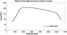
- FIG. 1 illustrates the maximum engine torque as a function of speed
- FIG. 2 illustrates the maximum force on a vehicle as a function of speed
- FIG. 3 illustrates the envelope of the maximum force on a vehicle as a function of speed
- FIG. 4 illustrates a curve of maximum force achievable for drivability
- FIG. 5 illustrates a curve of the current maximum force
- FIG. 6 illustrates a method for determining a degradation coefficient
- FIG. 7 illustrates various vehicle limitations as a function of speed.
- FIG. 1 illustrates, for a given power train, the trend of the maximum engine torque that the latter can produce in newton-meters (Nm) represented on the y axis, as a function of the engine speed in revolutions per minute (rpm), represented on the x axis.
- Nm newton-meters
- rpm revolutions per minute
- FIG. 2 shows that that is true whatever the gear, which can vary from 1 to 6 in the example of this figure, each of the 6 gears corresponding to a curve in FIG. 2 , even if the amplitude of variation of this force transmitted to the vehicle decreases very strongly from one gear to a higher gear. It should be noted that that is also true in the case of a thermal or electrical power train.
- this curve of force transmitted to the vehicle comprises numerous fairly abrupt inflection points, which are reflected in the form of discontinuities or jerks in the acceleration of the vehicle. It should be noted that these discontinuities or these jerks are perceived more by the driver if the vehicle has a transmission of DCT or IVT type, commonly used on HEVs.
- one of the principles of the invention is to define a curve of maximum force achievable for drivability, called “drivability force” in the figure, this curve being always slightly below the curve of theoretical force that the vehicle can provide, called “theoretical max force” in the figure.
- the “drivability force” curve is the upwardly concave parabolic curve, which is lower than the “theoretical max force” curve at all points, and which passes through numerous inflection points of the “theoretical max force” curve, at least one in all cases.
- the performance levels of the vehicle in terms of pure acceleration may indeed be reduced, but, equally, all the discontinuities or jerks are eliminated: the acceleration is “smoothed” over all the range of the gears.
- This curve can be determined and memorized by the central computer of the vehicle, in the form of a discretized mapping for example.
- This first principle according to the invention namely using a “drivability force” curve for the maneuvers of “verve”, therefore offers the advantage of preventing the discontinuities or the jerks in the nominal cases of operation of the vehicle, that is to say when the battery is far from its minimum state of charge and when the temperature and pressure conditions are normal.
- a hybrid power train is not even capable of ensuring the maximum torque illustrated by the “drivability force” curve.
- the electric vehicle may not be capable of supplying the maximum electric torque necessary to follow the “theoretical max force” curve.
- the heat engine may not be capable of supplying the maximum thermal torque necessary to follow the “theoretical max force” curve.
- the performance levels of the power train can greatly decrease and, if nothing is done, the real limitation of the power train may become lower than the drivability limitation defined by the “drivability force” curve, as illustrated in FIG. 5 by a “current max force” curve.
- the use, in the creation of the will of the driver, of a drivability limitation according to the invention therefore becomes insufficient, because the curve of real limitation comprises numerous inflection points that are felt by the driver.
- the invention proposes determining a coefficient representing the current value of the performance degradation relative to the drivability force. In this way, it is possible to adapt or correct in real time the curve of drivability limitation, in order to transmit a corrected force during a verve maneuver.
- a degradation coefficient Coef_degr can be computed as illustrated by FIG. 6 .
- the first step is to compute, in a software block 71 , the degradation coefficient by comparing the maximum force available at the current instant t, called Force_max_current, which is conventionally made available by the central computer of the vehicle, with the nominal drivability force, called Force_nom_driv, supplied by the curve of drivability limitation according to the invention and stored in the memory of the central computer.
- the block 71 supplies as output the degradation coefficient, which is memorized in a variable Coef_degr by a software block 72 .
- Coef_degr lies between 0 and 1, where 0 represents the maximum degradation and 1 the absence of degradation.
- Coef_degr is then compared to the previously computed last value of the degradation coefficient, which is memorized in a variable Coef_degr_mem. It can be noted that, for the first iteration, Coef_degr_mem is initialized at 1, which is the nominal value of the degradation coefficient.
- Coef_degr_mem is incremented by a software block 75 by an offset “Inc” dependent on the current instant t supplied by a software block 76 , so as to go back up little by little to the nominal value of the degradation coefficient, namely 1.
- FIG. 7 illustrates, on the one hand, a curve of nominal drivability limitation according to the invention, a curve of “real” current limitation with numerous force discontinuities, the trend of the degradation coefficient which results from the comparison of the two preceding curves according to the method illustrated by FIG. 6 , and finally the curve of corrected drivability which results from the application of the degradation coefficient to the curve of nominal drivability limitation, according to the method illustrated by FIG. 6 .
- the corrected drivability limitation is modulated to be always located below what can actually be produced by the vehicle, that is to say below the curve of “real” current limitation.
- the driver in a “verve” maneuver, the driver can have access only to the corrected drivability limitation and thus is no longer affected by the real current limitation, which includes force discontinuities. These force discontinuities are therefore not felt by the driver.
- the driver could first of all choose an energy mode of the vehicle out of:
- Another advantage of the present invention is that the torque limitation is transparent to the driver: there is very little chance that he or she will perceive it from one “verve” maneuver to another.
- the invention makes it possible to always maintain the level of charge of the battery at an acceptable level, such that the system is never destabilized (particularly by maintaining the state of charge of the traction battery within an operational range), and even if the driver strings together “verve” maneuvers.
Landscapes
- Engineering & Computer Science (AREA)
- Transportation (AREA)
- Mechanical Engineering (AREA)
- Automation & Control Theory (AREA)
- Physics & Mathematics (AREA)
- Mathematical Physics (AREA)
- Chemical & Material Sciences (AREA)
- Combustion & Propulsion (AREA)
- Electric Propulsion And Braking For Vehicles (AREA)
- Hybrid Electric Vehicles (AREA)
Abstract
Description
-
- “auto hybrid”: the energy management law would be free to choose the operation without constraint from the driver;
- “forced ZEV”: the driver could prioritize the use of running in pure electric mode, via battery discharge, because he or she is driving in a town for example;
- “range saver”: the driver could prioritize maintaining the battery charge via the increased use of the heat engine, for example because he or she knows that he or she will finish his or her journey in town and that he or she will then switch to “forced ZEV” mode. A curve of drivability limitation and therefore a drivability force could then be deduced as a function of the energy mode chosen.
Claims (5)
Applications Claiming Priority (3)
| Application Number | Priority Date | Filing Date | Title |
|---|---|---|---|
| FR1652411 | 2016-03-21 | ||
| FR1652411A FR3048937B1 (en) | 2016-03-21 | 2016-03-21 | METHOD FOR DETERMINING THE MAXIMUM FORCE TO BE TRANSMITTED TO THE DRIVING WHEELS OF A VEHICLE EQUIPPED WITH A HYBRID DRIVE UNIT |
| PCT/FR2017/050613 WO2017162959A1 (en) | 2016-03-21 | 2017-03-16 | Method for determining the maximum force to be transmitted to the driving wheels of a vehicle provided with a hybrid power train |
Publications (2)
| Publication Number | Publication Date |
|---|---|
| US20190193718A1 US20190193718A1 (en) | 2019-06-27 |
| US11052902B2 true US11052902B2 (en) | 2021-07-06 |
Family
ID=55953281
Family Applications (1)
| Application Number | Title | Priority Date | Filing Date |
|---|---|---|---|
| US16/086,932 Active 2038-03-20 US11052902B2 (en) | 2016-03-21 | 2017-03-16 | Method for determining the maximum force to be transmitted to the driving wheels of a vehicle provided with a hybrid power train |
Country Status (6)
| Country | Link |
|---|---|
| US (1) | US11052902B2 (en) |
| EP (1) | EP3433149B1 (en) |
| KR (1) | KR102331243B1 (en) |
| CN (1) | CN109070875B (en) |
| FR (1) | FR3048937B1 (en) |
| WO (1) | WO2017162959A1 (en) |
Families Citing this family (3)
| Publication number | Priority date | Publication date | Assignee | Title |
|---|---|---|---|---|
| CN112660102B (en) * | 2020-12-31 | 2022-05-17 | 吉林大学 | A control method of planetary multi-speed hybrid power system based on energy consumption analysis theory |
| FR3123866B1 (en) * | 2021-06-14 | 2023-05-26 | Renault Sas | Method for controlling an automatic transmission in the event of a drop in powertrain performance |
| CN115914235A (en) * | 2022-11-29 | 2023-04-04 | 中国银行股份有限公司 | Load balancing method and device |
Citations (8)
| Publication number | Priority date | Publication date | Assignee | Title |
|---|---|---|---|---|
| DE19945449A1 (en) | 1998-09-22 | 2000-03-30 | Nissan Motor | Open/closed loop control device for output power of hybrid vehicle has device to increase or decrease output speed of engine, sensor for output power and microprocessor to control device |
| US6076032A (en) * | 1996-04-26 | 2000-06-13 | Honda Giken Kogyo Kabushiki Kaisha | Control system for vehicle for controlling the driving force depending on operating conditions of the vehicle |
| DE10249689A1 (en) | 2002-10-25 | 2004-05-13 | Bayerische Motoren Werke Ag | Controlling motor vehicle drive involves determining desired engine torque, gear from stored curves depending on speed and selecting desired traction force depending on power demand, other parameters |
| DE102004051004B3 (en) | 2004-10-20 | 2006-06-01 | Bayerische Motoren Werke Ag | Longitudinal dynamics control system in motor vehicles |
| US20130261862A1 (en) * | 2012-03-30 | 2013-10-03 | Honda Motor Co., Ltd. | Vehicle and method for controlling vehicle |
| FR3004231A1 (en) | 2013-04-05 | 2014-10-10 | Renault Sa | METHOD FOR CONTROLLING THE STATE OF A CINEMATIC CHAIN OF A MOTORPOWER GROUP OF A HYBRID OR THERMAL ELECTRIC VEHICLE |
| US20170057494A1 (en) * | 2015-08-27 | 2017-03-02 | Fuji Jukogyo Kabushiki Kaisha | Apparatus and method for controlling vehicle |
| US20170137023A1 (en) * | 2014-04-02 | 2017-05-18 | Levant Power Corporation | Active safety suspension system |
Family Cites Families (22)
| Publication number | Priority date | Publication date | Assignee | Title |
|---|---|---|---|---|
| US6453222B1 (en) * | 2000-10-31 | 2002-09-17 | Volvo Car Corporation | Method and arrangement in a hybrid vehicle for matching engine and generator torques at times of engagement and disengagement |
| US6819997B2 (en) * | 2003-02-21 | 2004-11-16 | Borgwarner, Inc. | Method of controlling a dual clutch transmission |
| JP4365354B2 (en) * | 2005-07-14 | 2009-11-18 | トヨタ自動車株式会社 | Power output apparatus, automobile equipped with the same, and control method of power output apparatus |
| US8050856B2 (en) * | 2007-04-18 | 2011-11-01 | Chrysler Group Llc | Methods and systems for powertrain optimization and improved fuel economy |
| US7873452B2 (en) * | 2007-08-03 | 2011-01-18 | Detroit Diesel Corporation | Method and system for controlling a vehicle powertrain based upon actual vehicle load |
| US8010247B2 (en) * | 2007-11-03 | 2011-08-30 | GM Global Technology Operations LLC | Method for operating an engine in a hybrid powertrain system |
| JP5017450B2 (en) * | 2008-03-31 | 2012-09-05 | アイシン・エーアイ株式会社 | Hybrid power unit |
| AU2010347249B2 (en) * | 2010-03-02 | 2014-05-08 | International Truck Intellectual Property Company, Llc | Regenerative brake system reset feature and adaptive calibration for hybrid and electric vehicles |
| WO2011114425A1 (en) * | 2010-03-15 | 2011-09-22 | トヨタ自動車株式会社 | Vehicle control device |
| FR2958588B1 (en) * | 2010-04-08 | 2012-04-20 | Renault Sa | METHOD FOR CONTROLLING THE OPERATION OF A MECHANICAL COUPLING MEANS OF THE FIRST AND SECOND AXLES OF A MOTOR VEHICLE |
| DE102010028069A1 (en) * | 2010-04-22 | 2011-10-27 | Zf Friedrichshafen Ag | Method for switching control of a motor vehicle |
| WO2012105015A1 (en) * | 2011-02-02 | 2012-08-09 | トヨタ自動車株式会社 | Control device for vehicle driving apparatus |
| DE102012007621B4 (en) * | 2012-04-18 | 2017-11-02 | Voith Patent Gmbh | Method for building or reducing torque |
| DE102012024843A1 (en) * | 2012-12-19 | 2014-06-26 | Daimler Ag | Method for checking internal combustion engine of motor vehicle,involves operating electric machine of motor vehicle in checking mode, in which predetermined operating point of internal combustion engine is adjusted by electric machine |
| JP2014159238A (en) * | 2013-02-20 | 2014-09-04 | Toyota Motor Corp | Control unit of hybrid vehicle |
| EP2969683A4 (en) * | 2013-03-15 | 2017-01-25 | Allison Transmission, Inc. | System and method for energy rate balancing in hybrid automatic transmissions |
| WO2014174909A1 (en) * | 2013-04-23 | 2014-10-30 | 日産自動車株式会社 | Device for controlling hybrid vehicle |
| ITBO20130484A1 (en) | 2013-09-12 | 2015-03-13 | Magneti Marelli Spa | METHOD OF CONTROL OF A HYBRID VEHICLE DURING A GEAR SHIFT PHASE |
| KR101481335B1 (en) * | 2013-11-20 | 2015-01-09 | 현대자동차주식회사 | Shifting control method for hybrid vehicle |
| US10011282B2 (en) * | 2013-12-20 | 2018-07-03 | Volvo Truck Corporation | Prime mover arrangement and method for controlling speed and torque output of a prime mover arrangement |
| JP6070534B2 (en) * | 2013-12-24 | 2017-02-01 | 株式会社デンソー | Hybrid vehicle drive control device |
| CN104828093B (en) * | 2014-06-06 | 2017-09-12 | 北汽福田汽车股份有限公司 | Modification method, system and the vehicle with it of the shift sensor of vehicle |
-
2016
- 2016-03-21 FR FR1652411A patent/FR3048937B1/en not_active Expired - Fee Related
-
2017
- 2017-03-16 US US16/086,932 patent/US11052902B2/en active Active
- 2017-03-16 CN CN201780023686.8A patent/CN109070875B/en active Active
- 2017-03-16 EP EP17716566.9A patent/EP3433149B1/en active Active
- 2017-03-16 KR KR1020187030322A patent/KR102331243B1/en active Active
- 2017-03-16 WO PCT/FR2017/050613 patent/WO2017162959A1/en not_active Ceased
Patent Citations (11)
| Publication number | Priority date | Publication date | Assignee | Title |
|---|---|---|---|---|
| US6076032A (en) * | 1996-04-26 | 2000-06-13 | Honda Giken Kogyo Kabushiki Kaisha | Control system for vehicle for controlling the driving force depending on operating conditions of the vehicle |
| DE19945449A1 (en) | 1998-09-22 | 2000-03-30 | Nissan Motor | Open/closed loop control device for output power of hybrid vehicle has device to increase or decrease output speed of engine, sensor for output power and microprocessor to control device |
| US6155954A (en) * | 1998-09-22 | 2000-12-05 | Nissan Motor Co., Ltd. | Engine output control device for hybrid vehicle |
| DE10249689A1 (en) | 2002-10-25 | 2004-05-13 | Bayerische Motoren Werke Ag | Controlling motor vehicle drive involves determining desired engine torque, gear from stored curves depending on speed and selecting desired traction force depending on power demand, other parameters |
| DE102004051004B3 (en) | 2004-10-20 | 2006-06-01 | Bayerische Motoren Werke Ag | Longitudinal dynamics control system in motor vehicles |
| US20070198161A1 (en) * | 2004-10-20 | 2007-08-23 | Bayerische Motoren Werke Aktiengesellschaft | Longitudinal dynamics control system in motor vehicles |
| US20130261862A1 (en) * | 2012-03-30 | 2013-10-03 | Honda Motor Co., Ltd. | Vehicle and method for controlling vehicle |
| FR3004231A1 (en) | 2013-04-05 | 2014-10-10 | Renault Sa | METHOD FOR CONTROLLING THE STATE OF A CINEMATIC CHAIN OF A MOTORPOWER GROUP OF A HYBRID OR THERMAL ELECTRIC VEHICLE |
| US20160075323A1 (en) * | 2013-04-05 | 2016-03-17 | Renault S.A.S | Method for controlling the state of a drive train of a power train of an electric, hybrid or combustion engine vehicle |
| US20170137023A1 (en) * | 2014-04-02 | 2017-05-18 | Levant Power Corporation | Active safety suspension system |
| US20170057494A1 (en) * | 2015-08-27 | 2017-03-02 | Fuji Jukogyo Kabushiki Kaisha | Apparatus and method for controlling vehicle |
Non-Patent Citations (2)
| Title |
|---|
| French Preliminary Search Report dated Nov. 16, 2016 in Patent Application No. 1652411 filed Mar. 21, 2016. |
| International Search Report dated Jun. 8, 2017 in PCT/FR2017/050613 filed Mar. 16, 2017. |
Also Published As
| Publication number | Publication date |
|---|---|
| CN109070875B (en) | 2022-06-03 |
| FR3048937A1 (en) | 2017-09-22 |
| KR20180123128A (en) | 2018-11-14 |
| EP3433149A1 (en) | 2019-01-30 |
| US20190193718A1 (en) | 2019-06-27 |
| KR102331243B1 (en) | 2021-11-25 |
| CN109070875A (en) | 2018-12-21 |
| EP3433149B1 (en) | 2022-07-06 |
| FR3048937B1 (en) | 2018-03-09 |
| WO2017162959A1 (en) | 2017-09-28 |
Similar Documents
| Publication | Publication Date | Title |
|---|---|---|
| US10768635B2 (en) | Hybrid electric vehicle and platooning control method therefor | |
| KR101684542B1 (en) | System and method for engine stop control of hybrid vehicle | |
| US7976581B2 (en) | Electric power generation control method during idle charge in hybrid electric vehicle | |
| US10363918B2 (en) | Method for controlling torque reduction of hybrid vehicle | |
| US11433877B2 (en) | Hybrid vehicle and driving control method therefor | |
| CN106256627B (en) | Method and apparatus for controlling engine start time in hybrid vehicle | |
| US11225245B2 (en) | Vehicle and method for controlling the same | |
| CN101478172A (en) | Method for determining optimal operation point with respect to state of charge in hybrid electric vehicle | |
| CN109895778B (en) | Hybrid vehicle and shift control method for the hybrid vehicle | |
| US11110790B2 (en) | Control apparatus and control method for vehicle | |
| CN106256631B (en) | Apparatus and method for controlling torque reduction of hybrid electric vehicle | |
| CN104704737A (en) | Power generation control device | |
| KR102726807B1 (en) | Method for controlling connection of engine clutch in hybrid electric vehicle | |
| US11167746B2 (en) | Control apparatus and control method for vehicle | |
| US11052902B2 (en) | Method for determining the maximum force to be transmitted to the driving wheels of a vehicle provided with a hybrid power train | |
| US7328096B2 (en) | Driving force switching control apparatus | |
| US8228035B2 (en) | Regeneration capacity control method for a battery | |
| US11926310B2 (en) | Hybrid electric vehicle and method for controlling speed limit for the same | |
| US11479231B2 (en) | Device and method for controlling driving of electric four-wheel drive vehicle | |
| US10399426B2 (en) | Control device for hybrid vehicle and control method | |
| US11440419B2 (en) | Method of controlling gear shifting in electric vehicle | |
| KR20230143264A (en) | Hybrid electric vehicle and method of driving control for the same | |
| US10737683B2 (en) | Hybrid vehicle and method for controlling the same | |
| KR102785161B1 (en) | Hybrid vehicle and method of controlling speed limit for the same | |
| US12485770B2 (en) | Vehicle system and traction control method for the vehicle system |
Legal Events
| Date | Code | Title | Description |
|---|---|---|---|
| FEPP | Fee payment procedure |
Free format text: ENTITY STATUS SET TO UNDISCOUNTED (ORIGINAL EVENT CODE: BIG.); ENTITY STATUS OF PATENT OWNER: LARGE ENTITY |
|
| AS | Assignment |
Owner name: RENAULT S.A.S., FRANCE Free format text: ASSIGNMENT OF ASSIGNORS INTEREST;ASSIGNORS:LE-ROY, LOIC;RUEL, JEAN-MARTIN;SIGNING DATES FROM 20180921 TO 20181001;REEL/FRAME:047081/0133 |
|
| STPP | Information on status: patent application and granting procedure in general |
Free format text: DOCKETED NEW CASE - READY FOR EXAMINATION |
|
| STPP | Information on status: patent application and granting procedure in general |
Free format text: RESPONSE TO NON-FINAL OFFICE ACTION ENTERED AND FORWARDED TO EXAMINER |
|
| STPP | Information on status: patent application and granting procedure in general |
Free format text: NOTICE OF ALLOWANCE MAILED -- APPLICATION RECEIVED IN OFFICE OF PUBLICATIONS |
|
| STPP | Information on status: patent application and granting procedure in general |
Free format text: PUBLICATIONS -- ISSUE FEE PAYMENT VERIFIED |
|
| STCF | Information on status: patent grant |
Free format text: PATENTED CASE |
|
| AS | Assignment |
Owner name: RENAULT S.A.S., FRANCE Free format text: CHANGE OF NAME AND ADDRESS;ASSIGNOR:RENAULT S.A.S.;REEL/FRAME:066700/0545 Effective date: 20231127 |
|
| AS | Assignment |
Owner name: RENAULT S.A.S., FRANCE Free format text: CHANGE OF ADDRESS;ASSIGNOR:RENAULT S.A.S.;REEL/FRAME:066761/0907 Effective date: 20231127 |
|
| AS | Assignment |
Owner name: NEW H POWERTRAIN HOLDING, S.L.U., SPAIN Free format text: ASSIGNMENT OF ASSIGNORS INTEREST;ASSIGNOR:RENAULT S.A.S.;REEL/FRAME:067099/0560 Effective date: 20230831 |
|
| MAFP | Maintenance fee payment |
Free format text: PAYMENT OF MAINTENANCE FEE, 4TH YEAR, LARGE ENTITY (ORIGINAL EVENT CODE: M1551); ENTITY STATUS OF PATENT OWNER: LARGE ENTITY Year of fee payment: 4 |