US11051365B2 - Heating rod - Google Patents
Heating rod Download PDFInfo
- Publication number
- US11051365B2 US11051365B2 US15/487,014 US201715487014A US11051365B2 US 11051365 B2 US11051365 B2 US 11051365B2 US 201715487014 A US201715487014 A US 201715487014A US 11051365 B2 US11051365 B2 US 11051365B2
- Authority
- US
- United States
- Prior art keywords
- heating elements
- contact sheet
- heating
- section
- contact
- Prior art date
- Legal status (The legal status is an assumption and is not a legal conclusion. Google has not performed a legal analysis and makes no representation as to the accuracy of the status listed.)
- Active, expires
Links
- 238000010438 heat treatment Methods 0.000 title claims abstract description 128
- 239000000919 ceramic Substances 0.000 claims abstract description 9
- 238000002955 isolation Methods 0.000 claims description 11
- JRPBQTZRNDNNOP-UHFFFAOYSA-N barium titanate Chemical compound [Ba+2].[Ba+2].[O-][Ti]([O-])([O-])[O-] JRPBQTZRNDNNOP-UHFFFAOYSA-N 0.000 description 2
- 229910002113 barium titanate Inorganic materials 0.000 description 2
- 230000006978 adaptation Effects 0.000 description 1
- 229910052782 aluminium Inorganic materials 0.000 description 1
- XAGFODPZIPBFFR-UHFFFAOYSA-N aluminium Chemical compound [Al] XAGFODPZIPBFFR-UHFFFAOYSA-N 0.000 description 1
- 238000009413 insulation Methods 0.000 description 1
- 229910052751 metal Inorganic materials 0.000 description 1
- 239000002184 metal Substances 0.000 description 1
- 229920000642 polymer Polymers 0.000 description 1
Images


Classifications
-
- H—ELECTRICITY
- H05—ELECTRIC TECHNIQUES NOT OTHERWISE PROVIDED FOR
- H05B—ELECTRIC HEATING; ELECTRIC LIGHT SOURCES NOT OTHERWISE PROVIDED FOR; CIRCUIT ARRANGEMENTS FOR ELECTRIC LIGHT SOURCES, IN GENERAL
- H05B3/00—Ohmic-resistance heating
- H05B3/10—Heating elements characterised by the composition or nature of the materials or by the arrangement of the conductor
- H05B3/12—Heating elements characterised by the composition or nature of the materials or by the arrangement of the conductor characterised by the composition or nature of the conductive material
- H05B3/14—Heating elements characterised by the composition or nature of the materials or by the arrangement of the conductor characterised by the composition or nature of the conductive material the material being non-metallic
- H05B3/141—Conductive ceramics, e.g. metal oxides, metal carbides, barium titanate, ferrites, zirconia, vitrous compounds
-
- H—ELECTRICITY
- H05—ELECTRIC TECHNIQUES NOT OTHERWISE PROVIDED FOR
- H05B—ELECTRIC HEATING; ELECTRIC LIGHT SOURCES NOT OTHERWISE PROVIDED FOR; CIRCUIT ARRANGEMENTS FOR ELECTRIC LIGHT SOURCES, IN GENERAL
- H05B3/00—Ohmic-resistance heating
- H05B3/40—Heating elements having the shape of rods or tubes
- H05B3/42—Heating elements having the shape of rods or tubes non-flexible
-
- B—PERFORMING OPERATIONS; TRANSPORTING
- B60—VEHICLES IN GENERAL
- B60H—ARRANGEMENTS OF HEATING, COOLING, VENTILATING OR OTHER AIR-TREATING DEVICES SPECIALLY ADAPTED FOR PASSENGER OR GOODS SPACES OF VEHICLES
- B60H1/00—Heating, cooling or ventilating [HVAC] devices
- B60H1/22—Heating, cooling or ventilating [HVAC] devices the heat being derived otherwise than from the propulsion plant
- B60H1/2215—Heating, cooling or ventilating [HVAC] devices the heat being derived otherwise than from the propulsion plant the heat being derived from electric heaters
- B60H1/2218—Heating, cooling or ventilating [HVAC] devices the heat being derived otherwise than from the propulsion plant the heat being derived from electric heaters controlling the operation of electric heaters
-
- B—PERFORMING OPERATIONS; TRANSPORTING
- B60—VEHICLES IN GENERAL
- B60H—ARRANGEMENTS OF HEATING, COOLING, VENTILATING OR OTHER AIR-TREATING DEVICES SPECIALLY ADAPTED FOR PASSENGER OR GOODS SPACES OF VEHICLES
- B60H1/00—Heating, cooling or ventilating [HVAC] devices
- B60H1/22—Heating, cooling or ventilating [HVAC] devices the heat being derived otherwise than from the propulsion plant
- B60H1/2215—Heating, cooling or ventilating [HVAC] devices the heat being derived otherwise than from the propulsion plant the heat being derived from electric heaters
- B60H1/2225—Heating, cooling or ventilating [HVAC] devices the heat being derived otherwise than from the propulsion plant the heat being derived from electric heaters arrangements of electric heaters for heating air
-
- H—ELECTRICITY
- H05—ELECTRIC TECHNIQUES NOT OTHERWISE PROVIDED FOR
- H05B—ELECTRIC HEATING; ELECTRIC LIGHT SOURCES NOT OTHERWISE PROVIDED FOR; CIRCUIT ARRANGEMENTS FOR ELECTRIC LIGHT SOURCES, IN GENERAL
- H05B3/00—Ohmic-resistance heating
- H05B3/20—Heating elements having extended surface area substantially in a two-dimensional plane, e.g. plate-heater
- H05B3/22—Heating elements having extended surface area substantially in a two-dimensional plane, e.g. plate-heater non-flexible
- H05B3/24—Heating elements having extended surface area substantially in a two-dimensional plane, e.g. plate-heater non-flexible heating conductor being self-supporting
-
- H—ELECTRICITY
- H05—ELECTRIC TECHNIQUES NOT OTHERWISE PROVIDED FOR
- H05B—ELECTRIC HEATING; ELECTRIC LIGHT SOURCES NOT OTHERWISE PROVIDED FOR; CIRCUIT ARRANGEMENTS FOR ELECTRIC LIGHT SOURCES, IN GENERAL
- H05B3/00—Ohmic-resistance heating
- H05B3/40—Heating elements having the shape of rods or tubes
- H05B3/42—Heating elements having the shape of rods or tubes non-flexible
- H05B3/46—Heating elements having the shape of rods or tubes non-flexible heating conductor mounted on insulating base
-
- H—ELECTRICITY
- H05—ELECTRIC TECHNIQUES NOT OTHERWISE PROVIDED FOR
- H05B—ELECTRIC HEATING; ELECTRIC LIGHT SOURCES NOT OTHERWISE PROVIDED FOR; CIRCUIT ARRANGEMENTS FOR ELECTRIC LIGHT SOURCES, IN GENERAL
- H05B2203/00—Aspects relating to Ohmic resistive heating covered by group H05B3/00
- H05B2203/02—Heaters using heating elements having a positive temperature coefficient
Definitions
- the present invention relates to a heating rod of the type disclosed in DE 10 2012 107 113 A1.
- Such heating rods can be used for heating the interior of vehicles, for example.
- the heating power of such heating rods can be adjusted by pulse width modulation of the voltage applied to the heating rod. This involves a rather complicated controller.
- This disclosure shows how the heating power of a heating rod can be adjusted with less control effort.
- a first contact sheet electrically contacts only a first part of the plurality of the heating elements of the heating rod, whereas a second contact sheet contacts a second part of the plurality of heating rods.
- a heating rod according to this disclosure has three terminals, namely for applying a voltage to the first contact sheet, for applying a voltage to the second contact sheet and for a connection to ground.
- Prior art heating rods have only two terminals as voltage is either applied to all heating elements or to none.
- the second contact sheet electrically contacts only the second part of the plurality of heating elements and is electrically isolated from the first part of the plurality of heating elements. Then it is possible to activate either the first part or the second part of the plurality of heating elements or to activate all heating elements.
- the first part of the plurality of the heating elements and the second part of the plurality of the heating elements together can be all the heating elements of the heating rod. It is also possible that there is an additional contact sheet contacting another part of the plurality of heating elements.
- the first contact sheet and the second contact sheet are arranged on top of each other with an insulation layer between them.
- the first contact sheet is shorter than the second contact sheet so that the first contact sheet covers and electrically contacts only a first part of the plurality of the heating elements arranged in the housing.
- the second contact sheet covers the first contact sheet and extends beyond it so that it covers and electrically contacts the second part of the plurality of the heating elements arranged in the housing.
- the second contact sheet does not electrically contact the first part of the plurality of the heating elements arranged in the housing because of the isolation layer arranged between the first contact sheet and the second contact sheet.
- the second contact sheet may form a step between a first section of the second contact sheet covering the first contact sheet and a second section of the second contact sheet contacting the second part of the plurality of heating elements.
- the first contact sheet and the second contact sheet are arranged side by side.
- the second contact sheet may have a narrow section, which is arranged alongside the shorter first contact sheet, and a broad section contacting the second part of the plurality of heating elements.
- an isolation layer can be arranged between the narrow section and the first part of the plurality of heating elements so that the second contact sheet does not electrically contact the first part of the plurality of heating elements.
- the heating elements may be PTC heating elements, preferably on the basis of barium titanate.
- FIG. 1 shows an exploded view of a first illustrative embodiment of a heating rod
- FIG. 2 shows an exploded view of a second illustrative embodiment of a heating rod
- FIG. 3 shows the heating rod of FIG. 2 in a perspective view
- FIG. 4 shows a third illustrative embodiment shown without the housing
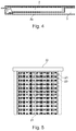
- FIG. 5 shows schematically a heating device comprising several heating rods.
- the heating rod shown in FIG. 1 comprises a plurality of resistive heating elements 1 , e.g., ceramic PTC heating elements on the basis of barium titanate.
- a first part of the plurality of heating elements namely the first two heating elements from the left in FIG. 1 , are electrically contacted by a first strip-shaped contact sheet 2 .
- a second part of the plurality of heating elements namely the third to fifth heating elements 1 from the left in FIG. 1 , are contacted by a second strip-shaped contact sheet 3 .
- the second contact sheet 3 is arranged on top of the first contact sheet 2 .
- the first contact sheet 2 and the second contact sheet 3 are electrically isolated from each other by an isolating layer 4 arranged between them.
- the second contact sheet 3 has a step 5 between a first section that is arranged above the first contact sheet 2 and a second section contacting the second part of the plurality of heating elements 1 .
- the heating elements 1 are held in a plastic frame 6 .
- the plastic frame 6 has on a front side two cut outs for a terminal section of the first contact sheet 2 and of the second contact sheet 3 .
- the ceramic heating elements 1 can be connected to ground via a housing 9 , in which the heating elements 1 , the contact sheets 2 , 3 and the frame 6 are arranged. In the embodiment shown in FIG. 1 , the heating elements 1 are connected to ground via a third contact sheet 8 . A first side of the ceramic heating elements 1 is in electrical contact with the third contact sheet 8 . The opposite side of the heating elements 1 is contacted by the first electrical sheet 2 or the second electrical contact sheet 3 , respectively.
- the plastic frame 6 has another cut out for a terminal section of the third contact sheet 8 .
- the contact sheets 2 , 3 , 8 are electrically isolated from the housing 9 , which may by a profile tube, e.g., of aluminum.
- the contact sheets 2 , 3 , 8 are electrically isolated from the housing 9 by means of isolating layers, e.g., polymer strips 10 and/or ceramic strips 11 .
- FIG. 2 shows an exploded view of a second illustrative embodiment of a heating rod.
- the second illustrative embodiment differs from the first illustrative embodiment mainly in the first contact sheet 2 and the second contact sheet 3 .
- the second contact sheet 3 is not arranged on top of the first contact sheet 2 . Instead, the second contact sheet 3 has a narrow section 3 a which is arranged alongside the first contact sheet 2 .
- the first contact sheet 2 is shorter than the second contact sheet 3 so that only the second contact sheet 3 can reach the second part of the plurality of heating elements 1 .
- An isolation layer 7 can be arranged between the narrow section 3 a of the second contact sheet 3 and the heating elements 1 , which are electrically contacted by the first contact sheet 2 only.
- the narrow section 3 a of the second contact sheet 3 is electrically isolated from the first part of the plurality of heating elements 1 .
- the first part of the plurality of heating elements are the first two heating elements 1 from the left.
- FIG. 3 shows the heating rod of FIG. 2 is a perspective view. As explained above, this heating rod has three terminals corresponding to the three contact sheets 2 , 3 , 8 .
- FIG. 4 shows schematically another illustrative embodiment of a heating rod.
- the heating rod is shown in FIG. 3 without the housing tube.
- This embodiment is similar to the embodiment of FIG. 2 and differs from it mainly in that the terminal end of the contact sheets 2 , 3 , 8 are not flush with each other, but at different positions with respect to the longitudinal direction of the housing.
- FIG. 5 shows schematically a heating device comprising several heating rods 20 .
- the heating rods 20 are connected to fins 21 , e.g., made of corrugated metal sheets.
- the fins 21 and the heating rods 20 are held in a frame 22 .
- Such a heating device can be used to heat air in vehicles.
Landscapes
- Engineering & Computer Science (AREA)
- Physics & Mathematics (AREA)
- Thermal Sciences (AREA)
- Mechanical Engineering (AREA)
- Chemical & Material Sciences (AREA)
- Ceramic Engineering (AREA)
- Air-Conditioning For Vehicles (AREA)
- Resistance Heating (AREA)
Abstract
Description
- 1 heating element
- 2 contact sheet
- 3 contact sheet
- 3 a narrow section of
sheet 3 - 4 isolating layer
- 5 step
- 6 frame
- 7 isolation layer
- 8 contact sheet
- 9 housing
- 10 isolation
- 11 isolation
- 20 heating rod
- 21 fins
- 22 frame
Claims (15)
Applications Claiming Priority (2)
| Application Number | Priority Date | Filing Date | Title |
|---|---|---|---|
| DE102016107035.1 | 2016-04-15 | ||
| DE102016107035.1A DE102016107035B4 (en) | 2016-04-15 | 2016-04-15 | heater |
Publications (2)
| Publication Number | Publication Date |
|---|---|
| US20170303341A1 US20170303341A1 (en) | 2017-10-19 |
| US11051365B2 true US11051365B2 (en) | 2021-06-29 |
Family
ID=59980408
Family Applications (1)
| Application Number | Title | Priority Date | Filing Date |
|---|---|---|---|
| US15/487,014 Active 2038-08-24 US11051365B2 (en) | 2016-04-15 | 2017-04-13 | Heating rod |
Country Status (3)
| Country | Link |
|---|---|
| US (1) | US11051365B2 (en) |
| CN (2) | CN107371282A (en) |
| DE (1) | DE102016107035B4 (en) |
Families Citing this family (1)
| Publication number | Priority date | Publication date | Assignee | Title |
|---|---|---|---|---|
| DE102021109618A1 (en) * | 2021-04-16 | 2022-10-20 | Eberspächer Catem Gmbh & Co. Kg | PTC heating device |
Citations (6)
| Publication number | Priority date | Publication date | Assignee | Title |
|---|---|---|---|---|
| US5471034A (en) * | 1993-03-17 | 1995-11-28 | Texas Instruments Incorporated | Heater apparatus and process for heating a fluid stream with PTC heating elements electrically connected in series |
| US20030132222A1 (en) * | 2001-12-06 | 2003-07-17 | Catem Gmbh & Co. Kg | Electric heating device |
| US20040169027A1 (en) * | 2003-02-28 | 2004-09-02 | Catem Gmbh & Co. Kg | Electric heating device with heating zones |
| US20090314764A1 (en) * | 2006-09-13 | 2009-12-24 | Calsonic Kansei Corporation | Electric heating device and manufacturing method thereof |
| DE102012107113A1 (en) | 2012-08-02 | 2014-02-06 | Borgwarner Beru Systems Gmbh | heater |
| KR101913121B1 (en) * | 2016-01-28 | 2018-10-31 | 자화전자(주) | Ptc heater and apparatus for heater using the same |
Family Cites Families (5)
| Publication number | Priority date | Publication date | Assignee | Title |
|---|---|---|---|---|
| DE10316908A1 (en) | 2003-04-12 | 2004-10-21 | Eichenauer Heizelemente Gmbh & Co. Kg | heater |
| DE102004050237A1 (en) | 2004-10-15 | 2006-04-27 | Daimlerchrysler Ag | Electric heater for automobiles has heat guidance element with two self regulating heating elements whereby heating elements are arranged in first row of contacting element and are directly connected to it |
| CN104203612B (en) * | 2012-02-28 | 2016-08-24 | 汉拿伟世通空调有限公司 | Vehicle heater |
| CN104053257A (en) * | 2014-06-10 | 2014-09-17 | 孝感华工高理电子有限公司 | PTC heating rod and manufacturing method thereof |
| JP5989044B2 (en) | 2014-08-12 | 2016-09-07 | 三菱電機株式会社 | Positive temperature coefficient thermistor device |
-
2016
- 2016-04-15 DE DE102016107035.1A patent/DE102016107035B4/en active Active
-
2017
- 2017-04-07 CN CN201710224547.3A patent/CN107371282A/en active Pending
- 2017-04-07 CN CN202211362512.3A patent/CN115707155A/en active Pending
- 2017-04-13 US US15/487,014 patent/US11051365B2/en active Active
Patent Citations (8)
| Publication number | Priority date | Publication date | Assignee | Title |
|---|---|---|---|---|
| US5471034A (en) * | 1993-03-17 | 1995-11-28 | Texas Instruments Incorporated | Heater apparatus and process for heating a fluid stream with PTC heating elements electrically connected in series |
| US20030132222A1 (en) * | 2001-12-06 | 2003-07-17 | Catem Gmbh & Co. Kg | Electric heating device |
| US20040169027A1 (en) * | 2003-02-28 | 2004-09-02 | Catem Gmbh & Co. Kg | Electric heating device with heating zones |
| US20090314764A1 (en) * | 2006-09-13 | 2009-12-24 | Calsonic Kansei Corporation | Electric heating device and manufacturing method thereof |
| DE102012107113A1 (en) | 2012-08-02 | 2014-02-06 | Borgwarner Beru Systems Gmbh | heater |
| US20140034634A1 (en) | 2012-08-02 | 2014-02-06 | BorgWarner BERY Systems GmbH | Heating rod |
| KR101913121B1 (en) * | 2016-01-28 | 2018-10-31 | 자화전자(주) | Ptc heater and apparatus for heater using the same |
| US20190084374A1 (en) * | 2016-01-28 | 2019-03-21 | Jahwa Electronics Co., Ltd. | Independently-controlled ptc heater and device |
Non-Patent Citations (1)
| Title |
|---|
| Machine translation of KR101913121B1 (Year: 2016). * |
Also Published As
| Publication number | Publication date |
|---|---|
| CN107371282A (en) | 2017-11-21 |
| DE102016107035A1 (en) | 2017-10-19 |
| DE102016107035B4 (en) | 2022-07-14 |
| CN115707155A (en) | 2023-02-17 |
| US20170303341A1 (en) | 2017-10-19 |
Similar Documents
| Publication | Publication Date | Title |
|---|---|---|
| CN106162955B (en) | Electric heating device | |
| US9297551B2 (en) | Heat generating element | |
| JP6763306B2 (en) | Electrical connection member and laminated board using it | |
| WO2012025111A3 (en) | Electrical vehicle heating device | |
| US20170303343A1 (en) | Heating rod with slotted contact sheet | |
| US11051365B2 (en) | Heating rod | |
| EP3579669A3 (en) | Deformed layer for short electric connection between structures of electric device | |
| JP2021010014A (en) | Electronic device for inrush current limiting and electronic device application | |
| EP1650770A4 (en) | Ptc thermistor and method for protecting circuit | |
| US20160001744A1 (en) | Window assembly | |
| US7974070B2 (en) | Multilayer ceramic device and mounting structure therefor | |
| US20170303339A1 (en) | Heating rod having a nickel plated contact sheet | |
| US9555690B2 (en) | Heating device composed of heating modules, and heating module for same | |
| US20210144811A1 (en) | PTC Heating Cell | |
| EP3470367B1 (en) | Ozone generation device | |
| CN104210329B (en) | Auto heater | |
| KR101430581B1 (en) | Impact sensing apparatus using fpcb and insulation sheet | |
| US9982911B2 (en) | Electrical heating device | |
| US20180366635A1 (en) | Multilayer actuator | |
| US20240057222A1 (en) | PTC Heating Device | |
| EP2991110B1 (en) | Circuit protection device | |
| EP2296432A1 (en) | Heat exchanger | |
| US20190225054A1 (en) | Heating device and method for producing a heating rod | |
| DE102005050500B4 (en) | Device and method for voltage detection on a fuel cell stack | |
| JP2019020398A5 (en) |
Legal Events
| Date | Code | Title | Description |
|---|---|---|---|
| STPP | Information on status: patent application and granting procedure in general |
Free format text: DOCKETED NEW CASE - READY FOR EXAMINATION |
|
| AS | Assignment |
Owner name: BORGWARNER LUDWIGSBURG GMBH, GERMANY Free format text: ASSIGNMENT OF ASSIGNORS INTEREST;ASSIGNORS:MAHER, ANTHONY;O'CARROLL, THOMAS;DUKES, KEVIN;AND OTHERS;SIGNING DATES FROM 20170714 TO 20171114;REEL/FRAME:044287/0574 |
|
| STPP | Information on status: patent application and granting procedure in general |
Free format text: NON FINAL ACTION MAILED |
|
| STPP | Information on status: patent application and granting procedure in general |
Free format text: NON FINAL ACTION MAILED |
|
| STPP | Information on status: patent application and granting procedure in general |
Free format text: RESPONSE TO NON-FINAL OFFICE ACTION ENTERED AND FORWARDED TO EXAMINER |
|
| STPP | Information on status: patent application and granting procedure in general |
Free format text: FINAL REJECTION MAILED |
|
| STPP | Information on status: patent application and granting procedure in general |
Free format text: DOCKETED NEW CASE - READY FOR EXAMINATION |
|
| STPP | Information on status: patent application and granting procedure in general |
Free format text: RESPONSE TO EX PARTE QUAYLE ACTION ENTERED AND FORWARDED TO EXAMINER |
|
| STPP | Information on status: patent application and granting procedure in general |
Free format text: NOTICE OF ALLOWANCE MAILED -- APPLICATION RECEIVED IN OFFICE OF PUBLICATIONS |
|
| STPP | Information on status: patent application and granting procedure in general |
Free format text: PUBLICATIONS -- ISSUE FEE PAYMENT VERIFIED |
|
| STCF | Information on status: patent grant |
Free format text: PATENTED CASE |