US11051103B2 - Sound output apparatus, display apparatus and method for controlling the same - Google Patents
Sound output apparatus, display apparatus and method for controlling the same Download PDFInfo
- Publication number
- US11051103B2 US11051103B2 US16/102,150 US201816102150A US11051103B2 US 11051103 B2 US11051103 B2 US 11051103B2 US 201816102150 A US201816102150 A US 201816102150A US 11051103 B2 US11051103 B2 US 11051103B2
- Authority
- US
- United States
- Prior art keywords
- sound
- housing
- guide tube
- speaker
- outputter
- Prior art date
- Legal status (The legal status is an assumption and is not a legal conclusion. Google has not performed a legal analysis and makes no representation as to the accuracy of the status listed.)
- Active, expires
Links
- 238000000034 method Methods 0.000 title claims abstract description 34
- 230000004308 accommodation Effects 0.000 claims abstract description 157
- 230000005855 radiation Effects 0.000 claims abstract description 106
- 238000003780 insertion Methods 0.000 claims abstract description 31
- 230000037431 insertion Effects 0.000 claims abstract description 31
- 238000012545 processing Methods 0.000 claims description 27
- 230000005236 sound signal Effects 0.000 claims description 22
- 238000005192 partition Methods 0.000 description 69
- 230000000694 effects Effects 0.000 description 36
- 238000004891 communication Methods 0.000 description 14
- 238000005452 bending Methods 0.000 description 10
- 238000013461 design Methods 0.000 description 10
- 238000010586 diagram Methods 0.000 description 10
- 102100033126 Phosphatidate cytidylyltransferase 2 Human genes 0.000 description 8
- 101710178746 Phosphatidate cytidylyltransferase 2 Proteins 0.000 description 8
- 101000980996 Arabidopsis thaliana Phosphatidate cytidylyltransferase 3 Proteins 0.000 description 7
- 101000623713 Homo sapiens Motile sperm domain-containing protein 3 Proteins 0.000 description 7
- 102100023091 Motile sperm domain-containing protein 3 Human genes 0.000 description 7
- 238000005516 engineering process Methods 0.000 description 6
- 230000007423 decrease Effects 0.000 description 5
- 238000010295 mobile communication Methods 0.000 description 5
- 102100033118 Phosphatidate cytidylyltransferase 1 Human genes 0.000 description 4
- 101710178747 Phosphatidate cytidylyltransferase 1 Proteins 0.000 description 4
- 230000005540 biological transmission Effects 0.000 description 4
- 230000008859 change Effects 0.000 description 4
- 238000009434 installation Methods 0.000 description 4
- 238000013507 mapping Methods 0.000 description 4
- 239000004065 semiconductor Substances 0.000 description 4
- 230000014509 gene expression Effects 0.000 description 3
- 230000008569 process Effects 0.000 description 3
- 230000002787 reinforcement Effects 0.000 description 3
- 230000004044 response Effects 0.000 description 3
- 230000008033 biological extinction Effects 0.000 description 2
- 230000005669 field effect Effects 0.000 description 2
- 239000004973 liquid crystal related substance Substances 0.000 description 2
- 238000012986 modification Methods 0.000 description 2
- 230000004048 modification Effects 0.000 description 2
- 230000003287 optical effect Effects 0.000 description 2
- 230000000007 visual effect Effects 0.000 description 2
- 229920001621 AMOLED Polymers 0.000 description 1
- 239000011358 absorbing material Substances 0.000 description 1
- 230000001154 acute effect Effects 0.000 description 1
- 230000003321 amplification Effects 0.000 description 1
- 238000004364 calculation method Methods 0.000 description 1
- 230000001413 cellular effect Effects 0.000 description 1
- 230000003247 decreasing effect Effects 0.000 description 1
- 230000006870 function Effects 0.000 description 1
- 238000003199 nucleic acid amplification method Methods 0.000 description 1
- 239000013307 optical fiber Substances 0.000 description 1
- APTZNLHMIGJTEW-UHFFFAOYSA-N pyraflufen-ethyl Chemical compound C1=C(Cl)C(OCC(=O)OCC)=CC(C=2C(=C(OC(F)F)N(C)N=2)Cl)=C1F APTZNLHMIGJTEW-UHFFFAOYSA-N 0.000 description 1
- 230000009467 reduction Effects 0.000 description 1
- 239000007787 solid Substances 0.000 description 1
- 239000000758 substrate Substances 0.000 description 1
- 230000002194 synthesizing effect Effects 0.000 description 1
Images


Classifications
-
- H—ELECTRICITY
- H04—ELECTRIC COMMUNICATION TECHNIQUE
- H04R—LOUDSPEAKERS, MICROPHONES, GRAMOPHONE PICK-UPS OR LIKE ACOUSTIC ELECTROMECHANICAL TRANSDUCERS; DEAF-AID SETS; PUBLIC ADDRESS SYSTEMS
- H04R5/00—Stereophonic arrangements
- H04R5/02—Spatial or constructional arrangements of loudspeakers
-
- G—PHYSICS
- G06—COMPUTING; CALCULATING OR COUNTING
- G06F—ELECTRIC DIGITAL DATA PROCESSING
- G06F1/00—Details not covered by groups G06F3/00 - G06F13/00 and G06F21/00
- G06F1/16—Constructional details or arrangements
- G06F1/1601—Constructional details related to the housing of computer displays, e.g. of CRT monitors, of flat displays
- G06F1/1605—Multimedia displays, e.g. with integrated or attached speakers, cameras, microphones
-
- H—ELECTRICITY
- H04—ELECTRIC COMMUNICATION TECHNIQUE
- H04R—LOUDSPEAKERS, MICROPHONES, GRAMOPHONE PICK-UPS OR LIKE ACOUSTIC ELECTROMECHANICAL TRANSDUCERS; DEAF-AID SETS; PUBLIC ADDRESS SYSTEMS
- H04R1/00—Details of transducers, loudspeakers or microphones
- H04R1/20—Arrangements for obtaining desired frequency or directional characteristics
- H04R1/22—Arrangements for obtaining desired frequency or directional characteristics for obtaining desired frequency characteristic only
- H04R1/30—Combinations of transducers with horns, e.g. with mechanical matching means, i.e. front-loaded horns
-
- G—PHYSICS
- G10—MUSICAL INSTRUMENTS; ACOUSTICS
- G10K—SOUND-PRODUCING DEVICES; METHODS OR DEVICES FOR PROTECTING AGAINST, OR FOR DAMPING, NOISE OR OTHER ACOUSTIC WAVES IN GENERAL; ACOUSTICS NOT OTHERWISE PROVIDED FOR
- G10K11/00—Methods or devices for transmitting, conducting or directing sound in general; Methods or devices for protecting against, or for damping, noise or other acoustic waves in general
- G10K11/18—Methods or devices for transmitting, conducting or directing sound
- G10K11/22—Methods or devices for transmitting, conducting or directing sound for conducting sound through hollow pipes, e.g. speaking tubes
-
- H—ELECTRICITY
- H04—ELECTRIC COMMUNICATION TECHNIQUE
- H04N—PICTORIAL COMMUNICATION, e.g. TELEVISION
- H04N21/00—Selective content distribution, e.g. interactive television or video on demand [VOD]
- H04N21/40—Client devices specifically adapted for the reception of or interaction with content, e.g. set-top-box [STB]; Operations thereof
- H04N21/43—Processing of content or additional data, e.g. demultiplexing additional data from a digital video stream; Elementary client operations, e.g. monitoring of home network or synchronising decoder's clock; Client middleware
- H04N21/439—Processing of audio elementary streams
-
- H—ELECTRICITY
- H04—ELECTRIC COMMUNICATION TECHNIQUE
- H04N—PICTORIAL COMMUNICATION, e.g. TELEVISION
- H04N5/00—Details of television systems
- H04N5/64—Constructional details of receivers, e.g. cabinets or dust covers
-
- H—ELECTRICITY
- H04—ELECTRIC COMMUNICATION TECHNIQUE
- H04R—LOUDSPEAKERS, MICROPHONES, GRAMOPHONE PICK-UPS OR LIKE ACOUSTIC ELECTROMECHANICAL TRANSDUCERS; DEAF-AID SETS; PUBLIC ADDRESS SYSTEMS
- H04R1/00—Details of transducers, loudspeakers or microphones
- H04R1/02—Casings; Cabinets ; Supports therefor; Mountings therein
- H04R1/025—Arrangements for fixing loudspeaker transducers, e.g. in a box, furniture
-
- H—ELECTRICITY
- H04—ELECTRIC COMMUNICATION TECHNIQUE
- H04R—LOUDSPEAKERS, MICROPHONES, GRAMOPHONE PICK-UPS OR LIKE ACOUSTIC ELECTROMECHANICAL TRANSDUCERS; DEAF-AID SETS; PUBLIC ADDRESS SYSTEMS
- H04R1/00—Details of transducers, loudspeakers or microphones
- H04R1/20—Arrangements for obtaining desired frequency or directional characteristics
- H04R1/32—Arrangements for obtaining desired frequency or directional characteristics for obtaining desired directional characteristic only
- H04R1/34—Arrangements for obtaining desired frequency or directional characteristics for obtaining desired directional characteristic only by using a single transducer with sound reflecting, diffracting, directing or guiding means
- H04R1/345—Arrangements for obtaining desired frequency or directional characteristics for obtaining desired directional characteristic only by using a single transducer with sound reflecting, diffracting, directing or guiding means for loudspeakers
-
- H—ELECTRICITY
- H04—ELECTRIC COMMUNICATION TECHNIQUE
- H04R—LOUDSPEAKERS, MICROPHONES, GRAMOPHONE PICK-UPS OR LIKE ACOUSTIC ELECTROMECHANICAL TRANSDUCERS; DEAF-AID SETS; PUBLIC ADDRESS SYSTEMS
- H04R3/00—Circuits for transducers, loudspeakers or microphones
-
- H—ELECTRICITY
- H04—ELECTRIC COMMUNICATION TECHNIQUE
- H04R—LOUDSPEAKERS, MICROPHONES, GRAMOPHONE PICK-UPS OR LIKE ACOUSTIC ELECTROMECHANICAL TRANSDUCERS; DEAF-AID SETS; PUBLIC ADDRESS SYSTEMS
- H04R3/00—Circuits for transducers, loudspeakers or microphones
- H04R3/12—Circuits for transducers, loudspeakers or microphones for distributing signals to two or more loudspeakers
-
- H—ELECTRICITY
- H04—ELECTRIC COMMUNICATION TECHNIQUE
- H04N—PICTORIAL COMMUNICATION, e.g. TELEVISION
- H04N5/00—Details of television systems
- H04N5/64—Constructional details of receivers, e.g. cabinets or dust covers
- H04N5/642—Disposition of sound reproducers
-
- H—ELECTRICITY
- H04—ELECTRIC COMMUNICATION TECHNIQUE
- H04R—LOUDSPEAKERS, MICROPHONES, GRAMOPHONE PICK-UPS OR LIKE ACOUSTIC ELECTROMECHANICAL TRANSDUCERS; DEAF-AID SETS; PUBLIC ADDRESS SYSTEMS
- H04R2499/00—Aspects covered by H04R or H04S not otherwise provided for in their subgroups
- H04R2499/10—General applications
- H04R2499/15—Transducers incorporated in visual displaying devices, e.g. televisions, computer displays, laptops
Definitions
- the disclosure relates to a sound output apparatus, a display apparatus and a method for controlling the same.
- a sound output apparatus is an apparatus capable of outputting a sound.
- a sound output apparatus may include a speaker device or an earphone device for generating sound waves.
- a sound output apparatus generates an acoustic wave by applying an electrical signal to a diaphragm provided in a speaker device or the like to vibrate it, such that a wavelength corresponding to the vibration of the diaphragm is generated in the air.
- An example of a sound output apparatus includes a digital television.
- a digital television is a type of display apparatus, and represents an apparatus capable of providing at least one of image data and audio data to a user.
- a digital television converts multimedia data received from an external source (e.g., a broadcast transmission device) via a communication network and/or multimedia data stored in the form of an electric record stored in an embedded recording medium into visual information and auditory information so as to output the visual information and auditory information to a user.
- An external source e.g., a broadcast transmission device
- multimedia data stored in the form of an electric record stored in an embedded recording medium so as to output the visual information and auditory information to a user.
- a digital television may be used in various fields such as home and business.
- a thickness of digital televisions has become relatively thin, and in many cases, the screen is curved concavely to have a curved surface shape.
- a sound output apparatus capable of implementing the high immersive effect and wide sound field.
- a sound output apparatus includes: a housing; and at least one speaker provided on a surface of the housing, wherein the housing includes an accommodation portion provided with an insertion groove to which the at least one speaker is inserted and mounted, wherein the at least one speaker includes: a sound generator configured to generate a sound; and a guide tube that has a cross sectional area that changes from a first end of the guide tube to a second end of the guide tube, and wherein the guide tube receives the generated sound via the first end, and the guide tube includes an outer surface having a plurality of radiation apertures arranged in at least one row.
- the at least one speaker may be provided on the surface of the housing such that the outer surface of the guide tube having the plurality of radiation apertures extends in a direction in parallel to the surface of the housing, a direction inclined with respect to the surface of the housing or a direction toward a normal of the surface of the housing.
- the at least one speaker may be provided on at least one of an upper portion of the surface of the housing, a middle portion of the surface of the housing, and a lower portion of the surface of the housing.
- the guide tube may extend in a direction parallel to an upper portion boundary or a side portion boundary of the surface of the housing.
- the accommodation portion provided with the insertion groove may include at least one of: a first accommodation portion provided with a first insertion groove to which the at least one speaker may be inserted and mounted, wherein the first insertion groove may protrude from the surface of the housing; a second accommodation portion provided with a second insertion groove to which the at least one speaker may be inserted and mounted, wherein the second insertion groove may be recessed in the surface of the housing, formed to be in parallel to the surface of the housing, or formed to be inclined with respect to the surface of the housing; and a third accommodation portion provided with a third insertion groove to which the at least one speaker may be inserted and mounted, wherein the third insertion groove may be formed to be inserted into the surface of the housing.
- the first insertion groove may face an upper end of the housing, a side end of the housing, or a lower end of the housing.
- the second insertion groove may face in a direction inclined with respect to the surface of the housing, a direction of the normal of the surface of the housing or a tangential direction of the surface of the housing.
- the sound output apparatus may further include a processor configured to distribute an audio signal including of a signal of at least one channel, to the at least one speaker.
- the processor may be further configured to perform at least one of up-mixing and down-mixing on the audio signal.
- the at least one speaker may include at least two speakers provided on the housing.
- the processor may be further configured to distribute the audio signal to the sound generator of the two speakers.
- the sound output apparatus may further include a display panel provided on another surface opposite to the surface of the housing.
- the surface of the housing may be an upper surface of the housing or a side surface of the housing.
- the display panel may include a rigid display panel or a flexible display panel.
- the plurality of radiation apertures may face in a direction toward an upper end of the housing, a direction opposite to a direction to which the display panel is directed, a side surface direction of the housing, a direction toward of a lower end of the housing, or a direction in a range between the direction toward the upper end of the housing and the direction opposite to the direction to which the display panel is directed.
- a control method of a sound output apparatus includes: obtaining an audio signal composed of a signal of at least one channel; distributing the audio signal to at least one speaker, wherein the at least one speaker is provided on a surface of a housing of the sound output apparatus; and radiating a sound from the at least one speaker, wherein the at least one speaker includes: a sound generator configured to generate the sound; and a guide tube that has a cross sectional area that changes from a first end of the guide tube to a second end of the guide tube, and wherein the guide tube receives the generated sound via the first end, and the guide tube includes an outer surface having a plurality of radiation apertures arranged in at least one row.
- the control method may further include performing at least one of up-mixing and down-mixing on the audio signal.
- the control method may further include performing sound processing by applying a predetermined algorithm to the audio signal.
- a display apparatus includes: an exterior housing; a display panel installed on a first surface of the exterior housing; and at least one speaker provided on at least one of a second surface opposite to the first surface of the exterior housing and a side surface of the exterior housing, wherein the exterior housing includes an accommodation portion provided with an insertion groove to which the at least one speaker is inserted and mounted, wherein the at least one speaker includes: a sound generator configured to generate a sound; and a guide tube that has a cross sectional area that changes from a first end of the guide tube to a second end of the guide tube, and wherein the guide tube receives the generated sound via the first end, and the guide tube includes an outer surface having a plurality of radiation apertures is arranged in at least one row.
- FIG. 1 is a block diagram illustrating a sound output apparatus according to an embodiment
- FIG. 2 is a perspective view of a first sound outputter according to a first embodiment
- FIG. 3 is an exploded perspective view of the first sound outputter according to the first embodiment
- FIG. 4 is a cross-sectional view of the first sound outputter according to the first embodiment
- FIG. 5 is an enlarged view of an example of a region A in FIG. 4 ;
- FIG. 6 is an enlarged view of an example of a region B in FIG. 4 ;
- FIG. 7 is a perspective view of a first sound outputter according to a second embodiment
- FIG. 8 is a cross-sectional view of the first sound outputter according to the second embodiment.
- FIG. 9 is a perspective view of a first sound outputter according to a third embodiment.
- FIG. 10 is a cross-sectional view of a first sound outputter according to a fourth embodiment
- FIG. 11 is a cross-sectional view of a first sound outputter according to a fifth embodiment
- FIG. 12 is a cross-sectional view of a first sound outputter according to a sixth embodiment
- FIG. 13 is a cross-sectional view of a first sound outputter according to a seventh embodiment
- FIG. 14 is a cross-sectional view of a sound generator and a throat tube according to an eighth embodiment
- FIG. 15 is a front view illustrating a first embodiment of a display apparatus provided with the first sound outputter
- FIG. 16 is a rear view illustrating the first embodiment of the display apparatus provided with the first sound outputter
- FIG. 17 is a plan view illustrating the first embodiment of the display apparatus provided with the first sound outputter
- FIG. 18 is a cross-sectional view of a first accommodation portion
- FIG. 19 is a first view illustrating the radiation characteristics when a sound reflector is provided on a rear surface of the display apparatus
- FIG. 20 is a view illustrating the radiation characteristics when the sound reflector is solely provided
- FIG. 21 is a second view illustrating the radiation characteristics when the sound reflector is provided on the rear surface of the display apparatus
- FIGS. 22A and 22B are third views illustrating the radiation characteristics when the sound reflector is provided on the rear surface of the display apparatus
- FIG. 23 is a view illustrating an example of a sound radiation direction when the display apparatus is installed in a room
- FIGS. 24A to 24C are diagrams illustrating changes in intensity of sound received at one position in a room
- FIG. 24D is a diagram illustrating frequency characteristics with respect to time at one position in a room
- FIG. 25 is a view illustrating an example of a rear surface of the display apparatus provided with a second accommodation portion
- FIG. 26A is another view illustrating an example of the rear surface of the display apparatus provided with the second accommodation portion
- FIG. 26B is a sectional view of the second accommodation portion
- FIGS. 27A and 27B are diagrams illustrating the difference in the reflection characteristic of sound between the first sound outputter provided in the first accommodation portion and the first sound outputter provided in the second accommodation portion;
- FIG. 28 is a rear view illustrating a second embodiment of the display apparatus provided with the first sound outputter
- FIG. 29 is a cross-sectional view illustrating an embodiment of a third accommodation portion
- FIG. 30 is a cross-sectional view illustrating an embodiment of a fourth accommodation portion
- FIG. 31 is a view illustrating the radiation characteristics when the sound reflector is provided on the rear surface of the display apparatus according to the second embodiment
- FIG. 32 is a rear view illustrating a third embodiment of the display apparatus provided with the first sound outputter
- FIG. 33 is a cross-sectional view illustrating an embodiment of a fifth accommodation portion
- FIG. 34 is a view illustrating the radiation characteristics when the sound reflector is provided on the rear surface of the display apparatus according to the third embodiment
- FIG. 35 is a rear view illustrating a fourth embodiment of the display apparatus provided with the first sound outputter
- FIG. 36 is a view illustrating the radiation characteristics when the sound reflector is provided on the rear surface of the display apparatus according to the fourth embodiment
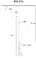
- FIG. 38 is a view illustrating an example of a curved surface display apparatus and a first sound outputter installed thereon according to a sixth embodiment of the display apparatus;
- FIG. 39 is a control block diagram according to an embodiment of the display apparatus.
- FIG. 40 is a flowchart illustrating an embodiment of a method for controlling the second sound outputter.
- part when a part “includes” or “comprises” an element, unless there is a particular description contrary thereto, the part may further include other elements, not excluding the other elements.
- the expression, “at least one of a, b, and c,” should be understood as including only a, only b, only c, both a and b, both a and c, both b and c, or all of a, b, and c.
- a sound output apparatus and a first sound outputter installed in the sound output apparatus will be described with reference to FIGS. 1 to 14 .
- FIG. 1 is a block diagram illustrating a sound output apparatus according to an embodiment.
- a sound output apparatus 10 may include a first sound outputter (or first speaker) 1 outputting a sound and a processor 30 controlling the first sound outputter 1 to output a sound.
- the sound may include voice, music, sound effects or various other sounds that can be transmitted in the form of waves.
- the sound output apparatus 10 represents an apparatus capable of outputting a sound to the outside.
- the sound output apparatus 10 may include a digital television apparatus, a radio apparatus, an audio apparatus, a phonograph, a voice recognition speaker apparatus, a compact disc player equipped with a speaker, a monitor apparatus provided with a speaker, a laptop computer, a tablet PC, a portable game machine, a navigation device, a personal digital assistant (PDA), a car audio device, an indoor or outdoor billboard, home appliance in which a speaker is installed, or a variety of devices capable of outputting a sound.
- PDA personal digital assistant
- the sound output apparatus 10 may include a single first sound outputter 1 - 1 or a plurality of first sound outputters 1 - 1 , 1 - 2 , . . . , 1 -N, (N is a natural number of 1 or more).
- the first sound outputters 1 - 1 , 1 - 2 , . . . , 1 -N may radiate different sounds from each other or radiate the same sound under the control of the processor 30 .
- the processor 30 may receive sound source data from at least one of a storage 41 , a wireless communicator 43 , a wired communicator 45 , and an input interface 47 , through a wire or a circuit.
- the sound source data may include audio data of at least one channel, and may further include metadata including information on audio data, as needed.
- the audio data of at least one channel may include two-channel audio data, three-channel audio data, four-channel audio data, or five-channel audio data.
- the at least one channel audio data may further include audio data reproduced by the woofer, such as 2.1 channel, or 5.1 channel.
- the at least one channel audio data may further include an upper speaker channel for a height (sound) effect, such as a 5.1.2 channel or a 7.1.4 channel.
- the sound source data may include audio data defined in various forms based on design considerations and requirements.
- the processor 30 may transmit sound source data without change or channel-mapped sound source data and/or additionally processed-sound source data to the first sound outputter 1 in the form of an electrical signal.
- the transmission of the sound source data can be implemented through a wire or a circuit.
- the storage 41 , the wireless communicator 43 , the wired communicator 45 and/or the input interface 47 are operated together with each other or operated independently of each other so as to provide the sound data to the processor 30 .
- the storage 41 may temporarily or non-temporarily store the sound source data and may transmit the sound source data to the processor 30 in response to a request from the processor 30 .
- the storage 41 may store various types of information required for calculation, processing or control operations of the processor 30 in an electronic form.
- the storage 41 may store all or a part of various data, an application, a filter, or an algorithm, that are required for the operation of the processor 30 .
- the application may be obtained through an electronic software distribution network that is accessible via the wireless communicator 43 or the wired communicator 45 .
- the storage 41 may include at least one of a main memory and an auxiliary memory.
- the main memory may be implemented using a semiconductor storage medium such as ROM and/or RAM.
- the ROM may include a conventional ROM, EPROM, EEPROM, and/or MASK-ROM.
- the RAM may include DRAM and/or SRAM.
- the auxiliary memory may be implemented by using at least one storage medium capable of permanently or semi-permanently storing data.
- the wireless communicator 43 may be configured to communicate with at least one of other external terminal apparatus and a server apparatus through a wireless communication network.
- the wireless communicator 43 may receive the sound source data from the other terminal apparatus or the server apparatus and transmit the received sound source data to the processor 30 .
- the external terminal device may include a smart phone, a cellular phone, a tablet PC, a laptop computer, a desktop computer, a wearable device, or other various communication devices.
- the wireless communicator 43 may be configured to perform communication with at least one of an external terminal device and a server device using a short range communication technology or configured to perform communication with at least one of a terminal device and a server device at a remote location using a mobile communication technology.
- the short range communication technology may include Bluetooth, Bluetooth Low Energy, CAN communication, Wi-Fi, Wi-Fi Direct, WiMAX, ultra-wide band (UWB), zigbee, infrared data association (IrDA), near field communication (NFC), or the like.
- the mobile communication technology may include a technology based on a mobile communication standard such as 3GPP, 3GPP2 or WiMAX series, wherein the mobile communication standard technology may include Global System for Mobile Communication (GSM), Enhanced Data GSM Environment (EDGE), Code Division Multiple Access (WCDMA), Code Division Multiple Access (CDMA), or (Time Division Multiple Access (TDMA).
- GSM Global System for Mobile Communication
- EDGE Enhanced Data GSM Environment
- WCDMA Code Division Multiple Access
- CDMA Code Division Multiple Access
- TDMA Time Division Multiple Access
- the input interface 47 may be connectable with other devices provided separately from the sound output apparatus 10 such as an external storage device.
- the input interface 47 may receive the sound source data from other devices and transmit the received sound source data to the processor 30 .
- FIG. 2 is a perspective view of a first sound outputter according to a first embodiment
- FIG. 3 is an exploded perspective view of the first sound outputter according to the first embodiment
- FIG. 4 is a cross-sectional view of the first sound outputter according to the first embodiment
- FIG. 5 is an enlarged view of an example of a region A in FIG. 4
- FIG. 6 is an enlarged view of an example of a region B in FIG. 4 .
- the first sound outputter 1 may include a sound generator (or driver) 11 configured to generate a sound, a guide tube 12 having a hollow tube shape and configured to guide the sound transmitted from the side of the sound generator 11 , to output the sound to the outside, a throat tube 13 disposed between the sound generator 11 and the guide tube 12 in such a manner that the sound generator 11 is installed at one side of the throat tube 13 and one end of the guide tube 12 is connected to the other side of the throat tube 13 , and a cap 14 configured to cover the other open end of the guide tube 12 .
- a sound generator (or driver) 11 configured to generate a sound
- a guide tube 12 having a hollow tube shape and configured to guide the sound transmitted from the side of the sound generator 11 , to output the sound to the outside
- a throat tube 13 disposed between the sound generator 11 and the guide tube 12 in such a manner that the sound generator 11 is installed at one side of the throat tube 13 and one end of the guide tube 12 is connected to the other side of the throat tube 13
- the sound generator 11 includes an electromagnet 11 a generating a magnetic force according to a received electric signal and a diaphragm 11 b is caused to vibrate by the electromagnet 11 a to generate sound as shown in FIG. 4 .
- the throat tube 13 has a hollow tube shape, and the inside of the throat tube 13 has a width or cross section that gradually increases (e.g., toward the guide tube 12 ). Therefore, the throat tube 13 guides the sound generated by the sound generator 11 to the guide tube 12 , while also reducing the noise that can be generated due to a sudden pressure change.
- the guide tube 12 may include a plurality of radiation apertures 12 a (i.e., sound radiation apertures) provided in a row along at least one side surface of the guide tube 12 in a longitudinal direction, to allow the sound to be radiated to the outside.
- the plurality of radiation apertures 12 a may be formed in at least one side surface of the guide tube 12 at equal intervals.
- Each of the radiation apertures 12 a may be formed as a circular hole, an elliptical hole, a polygonal hole (e.g., a square or a pentagon or other polygons) or a variety of hole shapes that may be designed.
- the radiation apertures 12 a may have sizes that gradually increase from a first end of the guide tube 12 on the side of the sound generator 11 to a second end on the opposite side. This allows a large amount of sound to be radiated through the radiation aperture 12 a at the second end of the guide tube 12 so that the directivity of the sound generated in the direction corresponding to the longitudinal direction of the guide tube 12 may be further increased.
- the plurality of radiation apertures 12 a may be arranged in a row on one side of the guide tube 12 .
- the plurality of radiation apertures 12 a may be arranged in a plurality of rows on one side of the guide tube 12 .
- the plurality of radiation apertures 12 a may be arranged in a single row or a plurality of rows on a plurality of sides of the guide tube 12 .
- the hollow guide tube 12 may be formed to have a substantially rectangular cross-section. However, it is merely an example and depending on embodiments, the guide tube 12 may be formed to have cross-sections corresponding to other shapes such as a circle or a triangle.
- the hollow guide tube 12 is configured such that a surface, on which the radiation apertures 12 a are disposed, forms a radiation surface 12 b from which the sound is radiated.
- the radiation apertures 12 a are arranged in a row on the radiation surface 12 b of the guide tube 12 , a portion of the sound transmitted through the throat tube 13 may be radiated to the outside through each of radiation apertures 12 a as the sound passes through the guide tube 12 .
- the sounds which are radiated through the radiation apertures 12 a provided in a row in the guide tube 12 with the time difference, perform extinction interference and constructive interference with each other. While the sounds interfere with each other, the sounds have a directivity in a direction corresponding to the longitudinal direction of the guide tube 12 . Accordingly, the first sound outputter 1 may operate as a directional speaker due to the structure of the guide tube 12 provided with the above-described radiation apertures 12 a.
- the inside of the guide tube 12 having a hollow tube shape, may have the same cross-sectional area or have a cross-sectional area gradually changes from the first end connected to the throat tube 13 to the second end on the opposite side (i.e., at the end where the cap 14 is located).
- the gradual change in the cross-sectional area may be a gradual decrease in the cross-sectional area or a gradual increase in the cross-sectional area. Depending on embodiments, this may include repeating the reduction and increase of the cross-sectional area.
- the sound transmitted to the guide tube 12 is sequentially radiated through the radiation apertures 12 a in the process of passing through the guide tube 12 . Accordingly, although the sound pressure gradually decreases in the process of passing through the guide tube 12 when an inner cross-sectional area of the guide tube 12 is gradually reduced, the radiation apertures 12 a adjacent to the other end of the guide tube 12 may radiate the sound at the same level as that of the other radiation apertures 12 a.
- the inner cross-sectional area of the guide tube 12 When the inner cross-sectional area of the guide tube 12 is gradually reduced from the first end of the guide tube 12 to the second end thereof, most of the sound passing through the guide tube 12 may be radiated to the outside by passing through the radiation apertures 12 a and thus the sound generated in the sound generator 11 is more efficiently radiated to the outside. In addition, as the sound radiated to the outside through the radiation apertures 12 a increases, the sound transmitted to the cap 14 placed at the second end of the guide tube 12 may decrease. In other words, by reducing the inner cross-sectional area of the guide tube 12 , it may be possible to reduce the noise generated when the sound arriving at the cap 14 is reflected back to the sound generator 11 side.
- the radiation surface 12 b may extend to form an acute angle relative to the longitudinal direction of the guide tube 12 as shown. Since the radiation apertures 12 a are provided on the radiation surface 12 b as described above, the sound is guided and radiated by the radiation surface 12 b.
- the radiation surface 12 b of the first sound outputter 1 may have a predetermined angle ⁇ with respect to the longitudinal direction of the guide tube 12 .
- the sound is guided and radiated by the radiation surface 12 b and thus the directivity of the first sound outputter 1 changes based on the angle ⁇ between the longitudinal direction of the guide tube 12 and the radiation surface 12 b .
- the directivity of the first sound outputter 1 increases corresponding with the increase of the angle ⁇ .
- the throat tube 13 is formed or provided in a hollow tube shape.
- a throat portion 13 a having a uniform cross-section that is smaller than other portions of the throat tube 13 may be formed in the portion adjacent to the sound generator, before the cross-section of the of the throat tube 13 gradually increases (e.g., toward the guide tube 12 ).
- the cap 14 is installed at the second end of the open guide tube 12 to close the second end of the guide tube 12 .
- An inner surface of the cap 14 opposite to the second end of the guide tube 12 is has a width that is gradually decreased to zero (0) in an upper and lower side so as to form a groove 14 a in a substantially V shape. Accordingly, the sound reaching the cap 14 may perform the extinction interference by being reflected by the inner surface of the cap 14 , and it may be possible to further reduce the noise that is generated when the sound reaching the second end of the guide tube 12 is reflected toward the sound generator 11 side (i.e., toward the first end of the guide tube 12 ). Furthermore, a sound absorbing material, such as a sponge, may be disposed at the inner surface of the cap 14 to further reduce noise.
- FIG. 7 is a perspective view of a first sound outputter according to a second embodiment
- FIG. 8 is a cross-sectional view of a first sound outputter according to the second embodiment
- FIG. 9 is a perspective view of a first sound outputter according to a third embodiment.
- a first sound outputter 1 - 1 includes a guide tube 12 - 1 having radiation apertures 12 a - 1 having the same size.
- the directivity of the sound generated in the first sound outputter 1 - 1 is relatively reduced compared with the first sound outputter 1 of the first embodiment.
- the intervals between the radiation apertures 12 a - 1 in a radiation surface 12 b - 1 may be equal to each other, as shown in FIG. 8 .
- a first sound outputter 1 - 2 includes a guide tube 12 - 2 having radiation apertures 12 a - 2 having a size that is gradually reduced from the first end of the guide tube 12 - 2 on the side of the sound generator 11 to the second end of the guide tube 12 - 2 on the opposite side.
- the size of the radiation aperture 12 a - 2 is gradually reduced from the first end of the guide tube 12 - 2 toward the second end of the guide tube 12 - 2 , the directivity of the sound generated by the first sound outputter 10 - 2 may be further reduced.
- the degree of directivity of the sound generated in the directional speaker can be determined and designed.
- FIG. 10 is a cross-sectional view of a first sound outputter according to a fourth embodiment
- FIG. 11 is a cross-sectional view of a first sound outputter according to a fifth embodiment.
- a first sound outputter 1 - 3 includes a guide tube 12 - 3 in which the interval between a plurality of radiation apertures 12 a - 3 in a radiation surface 12 - b 3 is set such that the intervals between the radiation apertures 12 a - 3 decrease from the first end at the side of the sound generator 11 to the second end.
- the interval between the radiation apertures 12 a - 3 formed in the vicinity the first end at the side of the sound generator 11 may be larger than the interval between the radiation apertures 12 a - 3 formed in the vicinity of the second end at the side of the cap 14 .
- the sizes of the plurality of radiation apertures 12 a - 3 may be different from each other, or may be substantially the same with each other.
- the number of radiation apertures 12 a - 3 provided on the second end side of the guide tube 12 - 3 is greater than the number of radiation apertures 12 a - 3 on the first end side of the guide tube 12 - 3 . Therefore, a larger amount of sound is radiated through the second end side of the guide tube 12 - 3 and thus the directivity of the sound formed in the direction corresponding to the longitudinal direction of the guide tube 12 - 3 may be further increased.
- a first sound outputter 1 - 4 includes a guide tube 12 - 4 in which the intervals between a plurality of radiation apertures 12 a - 4 in a radiation surface 12 b - 4 increase from a first end at the side of the sound generator 11 to the second end, as illustrated in FIG. 11 .
- the interval between the radiation apertures 12 a - 4 formed in the vicinity of the sound generator 11 may be less than the interval between the radiation apertures 12 a - 4 formed in the vicinity of the cap 14 .
- the sizes of the plurality of radiation apertures 12 a - 4 may be the same, or substantially the same as each other.
- the directivity of the first sound outputter is relatively reduced when the intervals are increased as mentioned above.
- the degree of directivity of the sound generated by the first sound outputter 1 can be selectively set by adjusting the intervals between the radiation apertures 12 a.
- FIG. 12 is a cross-sectional view of a first sound outputter according to a sixth embodiment
- FIG. 13 is a cross-sectional view of a first sound outputter according to a seventh embodiment.
- a first sound outputter 1 - 5 includes a guide tube 12 - 5 having a radiation surface 12 b - 5 that has a plurality of radiation apertures 12 a - 5 and extends in a direction parallel to the longitudinal direction of the guide tube 12 - 5 .
- the directivity of the first outputter 1 - 5 is relatively low because the angle ⁇ between the longitudinal direction of the guide tube 12 and the radiation surface 12 b shown in FIG. 4 is 0 (zero).
- a first sound outputter 1 - 6 includes a guide tube 12 - 6 having a radiation surface 12 b - 6 that has a plurality of radiation apertures 12 a - 6 extends in a direction having a relatively small angle ⁇ ′ with respect to the longitudinal direction of the guide tube 12 - 6 .
- ⁇ ′ the relatively small angle
- the degree of the directivity of the sound generated by the first sound outputter 1 can be selectively set.
- FIG. 14 is a cross-sectional view of a sound generator and a throat tube according to an eighth embodiment.
- a throat portion 13 a having a relatively smaller width than both adjacent portions may be formed in a portion adjacent to the sound generator 11 .
- the first sound outputter 1 applied to the display apparatus 2 may be configured to variably adjust the directivity of the sound transmitted from the first sound outputter 1 by adjusting the size of the radiation apertures 12 a provided in the guide tube 12 , the interval between the radiation apertures 12 a and the angle ⁇ of the radiation surface 12 b.
- FIGS. 15 to 38B various embodiments of a display apparatus ( 100 ) will be described with reference to FIGS. 15 to 38B as an example of a sound output apparatus in which a first sound outputter ( 101 ) is installed.
- the sound output apparatus 1 is not limited to being installing in a display apparatus.
- the first sound outputter is applicable to other devices that output sound, as well as the display apparatus.
- FIG. 15 is a front view illustrating a first embodiment of a display apparatus provided with the first sound outputter
- FIG. 16 is a rear view illustrating the first embodiment of the display apparatus provided with the first sound outputter
- FIG. 17 is a plan view illustrating the first embodiment of the display apparatus provided with the first sound outputter.
- a portion contacting the bottom surface is defined as a downward direction.
- a direction opposite to the downward direction is defined as an upward direction.
- a direction in which a display panel 191 is installed is defined as a forward direction
- a direction opposite to the forward direction is defined as a backward direction.
- any one of directions orthogonal to the upward direction, the downward direction, the backward direction, and the forward direction is defined as a right direction, and a direction opposite to the right direction is defined as a left direction.
- the display apparatus 100 refers to an apparatus capable of displaying an image externally.
- the display apparatus 100 may include a digital television apparatus, a monitor apparatus, a laptop computer, a smart phone, a tablet PC, a portable game machine, a navigation device or an indoor/outdoor billboard, but is not limited thereto.
- the display apparatus 100 may include the display panel 191 and a housing 190 in which the display panel 191 and various components related to operation of the display apparatus 10 are installed.
- the display panel 191 displays an image and provides the image to a user.
- the display panel 191 may include a liquid crystal display (LCD) using a liquid crystal, a display panel using a light emitting diode (LED) that emit light itself, a display panel using an organic light emitting diode (OLED) or an active-matrix organic light-emitting diode (OLED).
- LCD liquid crystal display
- LED light emitting diode
- OLED organic light emitting diode
- OLED active-matrix organic light-emitting diode
- the display apparatus 100 may further include a backlight unit (BLU) supplying light to the display panel 191 , as needed.
- BLU backlight unit
- the backlight unit may be installed in the housing 190 .
- the display panel 191 may be a rigid display panel or a flexible display panel.
- the display panel 191 may be exposed to the front side, and at least one first sound outputter 101 - 1 and 101 - 2 , may be installed on a rear surface 190 h , as illustrated in FIGS. 16 and 17 .
- the housing 190 may be implemented by a combination of a front frame, configured to allow the display panel 191 to be exposed to the outside and a rear frame configured to allow various components to be mounted.
- the housing 190 may be formed by integrating the front frame and the rear frame.
- the housing 190 may further include a stand 199 supporting the display apparatus 100 .
- the stand 199 may be provided at an appropriate position such as the bottom surface or the rear surface 190 h of the display apparatus 100 .
- the stand 199 may be omitted when the display apparatus 100 is mounted on the wall.
- a rear surface 100 e of the display apparatus 100 may further include parts needed for wall mounting.
- the first sound outputter 101 may be installed at a position on the rear surface 190 h of the housing 190 .
- the first sound outputter 101 - 1 may include a sound generator 111 , a guide tube 112 , a throat tube 113 , and a cap 114 .
- the rear surface 190 h of the housing 190 may be virtually or practically divided into an upper portion H 1 , a middle portion H 2 and a lower portion H 3 .
- the first sound outputter 101 may be installed in at least one of the upper portion H 1 , the middle portion H 2 , and the lower portion H 3 .
- the upper portion H 1 is defined to include a region from an upper end boundary e- 3 to one third (1 ⁇ 3) point of the entire length H, wherein the entire length H is from the upper end boundary e- 3 of the rear surface 190 h of the housing 190 to a lower end boundary e- 4 .
- the middle portion H 2 is defined to include a region from one third (1 ⁇ 3) point of the entire length H, wherein the entire length H is from the upper end boundary e- 3 of the rear surface 190 h of the housing 190 to the lower end boundary e- 4 , to two third (2 ⁇ 3) point of the entire length H, wherein the entire length H is in the direction from the upper end boundary e- 3 of the rear surface 190 h of the housing 190 to the lower end boundary e- 4 .
- the lower portion H 3 is defined to include a region from two third (2 ⁇ 3) point of the entire length H, wherein the entire length H is from the upper end boundary e- 3 of the rear surface 190 h of the housing 190 to the lower end boundary e- 4 , to the lower end boundary e- 4 .
- a definition may be arbitrarily changed depending on the design. Details of the installation position and operation of the first sound outputter 101 will be described later.
- the display apparatus 100 may further include second sound outputters 3 - 1 and 3 - 2 .
- the second sound outputters 3 - 1 and 3 - 2 may be implemented using a conventional speaker apparatus.
- the display apparatus 100 may include a single second sound outputter 3 - 1 or 3 - 2 , or as shown in FIGS. 15 and 16 , the display apparatus 100 may include two second sound output outputters 3 - 1 and 3 - 2 .
- the display apparatus 100 may include three or more second sound outputters 3 - 1 and 3 - 2 according to the design.
- the second sound outputters 3 - 1 and 3 - 2 may be installed in the housing 190 .
- the second sound outputters 3 - 1 and 3 - 2 may be installed inside the housing 190 to output the sound to the outside through holes provided in the housing 190 or may be installed directly on the outer surface of the housing 190 to output the sound to the outside.
- the second sound outputters 3 - 1 and 3 - 2 may be installed at the lower portion H 3 of the housing 190 .
- the installation positions of the second sound outputters 3 - 1 and 3 - 2 are not limited thereto.
- the second sound outputters 3 - 1 and 3 - 2 may be provided adjacent to the left and/or right boundaries of the housing 190 , wherein the second sound outputters 3 - 1 and 3 - 2 may be provided in substantially parallel to the left and/or right boundaries of the housing 190 .
- at least one second sound outputter 3 - 1 and 3 - 2 may be installed in at least one position that may be selected for a particular design.
- the first sound outputters 101 - 1 and 101 - 2 are symmetrically disposed at the rear surface 190 h of the housing 190 .
- the first sound outputters 101 - 1 and 101 - 2 may be disposed at the upper portion H 1 of the rear surface 190 h , as shown in FIG. 16 .
- the first sound outputters 101 - 1 and 101 - 2 may be disposed in contact with or adjacent to the upper end of the upper portion H 1 , that is, the upper end boundary e- 3 , or the first sound outputters 101 - 1 and 101 - 2 may be disposed in contact with or adjacent to the lower end of the upper portion H 1 .
- the first sound outputters 101 - 1 and 101 - 2 may be disposed in a middle line of the upper portion H 1 .
- the first sound outputters 101 - 1 and 101 - 2 may be installed in such a manner that the sound generator 111 faces the center line c and the cap 114 faces the left or right boundary e- 1 or e- 2 .
- the center line c indicates an imaginary line extending in the vertical direction and passing through the center of the rear surface 190 h of the housing 190 .
- the first sound outputters 101 - 1 and 101 - 2 may be installed on the rear surface 190 h parallel to or substantially parallel to the upper end boundary e- 3 .
- the first sound outputters 101 - 1 and 101 - 2 may be installed on the rear surface 190 h at a predetermined angle with respect to the upper end boundary e- 3 .
- the first sound outputters 101 - 1 and 101 - 2 may be installed in such a manner that one end thereof corresponding to the one end to which the cap 114 is mounted, is in contact with or adjacent to the left or right boundary e- 1 or e- 2 .
- the first sound outputters 101 - 1 and 101 - 2 may be installed in such a manner that the other end of the first sound outputters 101 - 1 and 101 - 2 corresponding to the end to which the sound generator 111 is mounted, is in contact with the center line c, adjacent to the center line c or spaced apart from the center line c by a predetermined distance.
- the predetermined distance may include an approximately half of the length of the first sound outputters 101 - 1 and 101 - 2 .
- the first sound outputters 101 - 1 and 101 - 2 may be installed in such a manner that the sound generator 111 faces the left or right boundary e- 1 or e- 2 and the cap 114 faces the center line c.
- One first sound outputter 101 - 1 may be installed in such a manner that the sound generator 111 faces the left or right boundary e- 1 or e- 2 and the cap 114 faces the center line c
- the other first sound outputter 101 - 2 may be installed in such a manner that the sound generator 111 faces the center line c and the cap 114 faces the left or right boundary e- 1 or e- 2 .
- the first sound outputters 101 - 1 and 101 - 2 may be installed in reverse to the method described above.
- the first sound outputters 101 - 1 and 101 - 2 may be installed in first accommodation portions 140 - 1 and 140 - 2 provided on the rear surface 190 h , and then installed on the rear surface 190 h of the housing 190 .
- a single first accommodation portion 140 - 1 or 140 - 2 may be installed on the rear surface 190 h of the housing 190
- two or more first accommodation portions 140 - 1 and 140 - 2 may be installed on the rear surface 190 h of the housing 190 .
- the number of the first accommodation portion 140 - 1 and 140 - 2 may correspond to the number of first sound outputters 101 - 1 and 101 - 2 to be installed.
- FIG. 18 is a cross-sectional view of a first accommodation portion. Particularly, FIG. 18 is a cross-sectional view of the first accommodation portion 140 - 1 , to which the first sound outputter 101 - 1 is mounted, taken along a line A-B.
- the first accommodation portion 140 - 1 may protrude backward and then installed on the rear surface 190 h .
- the first accommodation portion 140 - 1 may be exposed to the outside of the rear surface 190 h .
- the first accommodation portion 140 - 1 may be installed in such a manner that one end thereof faces the center line c and the other end thereof face the left or right boundary e- 1 or e- 2 , by corresponding to a structure in which the first sound outputter 101 - 1 is installed.
- the first accommodation portion 140 - 1 may be installed in such a manner that one end thereof is in contact with or adjacent to the left or right boundary e- 1 or e- 2 and the other thereof is in contact with or adjacent to the center line c, or spaced apart from the center line c with a predetermined distance.
- the first accommodation portion 140 - 1 may be installed on the rear surface 190 h parallel to or substantially parallel to the upper end boundary e- 3 , or the first accommodation portion 140 - 1 may be installed on the rear surface 190 h at a predetermined angle with respect to the upper end boundary e- 3
- an opening 141 radiating the sound generated by the first sound outputter 101 - 1 upward is formed.
- the opening 141 is formed between the first partition 140 a and the third partition 140 c .
- a fourth partition 140 d protruding toward the rear surface 190 h may be further provided at the end of the third partition 140 c , wherein the opening 141 may be disposed between the first partition 140 a and the fourth partition 140 d.
- the first to fourth partition 140 a to 140 d may be integrally formed or separately formed.
- the opening 141 may extend in the longitudinal direction in the upward direction of the first accommodation portion 140 - 1 in correspondence with radiation apertures 112 a formed along the outer surface of a guide tube 112 .
- the first sound outputter 101 - 1 may be inserted into the first accommodation portion 140 - 1 so that the radiation apertures 112 a , which are provided in the outer surface of the guide tube 112 of the first sound outputter 101 - 1 , corresponds to the opening 141 .
- the first sound outputter 101 - 1 may be installed in the first accommodation portion 140 - 1 so that the radiation apertures 112 a are exposed to the upward direction through the opening 141 .
- first accommodation groove of the first accommodation portion 140 - 1 is in the upward direction, but it may be possible to install the first accommodation groove of the first accommodation portion 140 - 1 to face the downward direction opposite to the above configuration discussed above.
- the first accommodation portion 140 - 1 may be installed to allow the first accommodation groove to face the backward direction, wherein the first accommodation portion 140 - 1 may be installed at the rear surface 190 h at about 90 degrees.
- FIG. 19 is a first view illustrating the radiation characteristics when a sound reflector is provided on a rear surface of the display apparatus
- FIG. 20 is a view illustrating the radiation characteristics when the sound reflector is solely provided
- FIG. 21 is a second view illustrating the radiation characteristics when the sound reflector is provided on the rear surface of the display apparatus.
- a relatively darker portion refers to a portion to which the sound is mainly or strongly transmitted (i.e., the superior portion)
- a relatively lighter portion refers to a portion to which the sound is relatively weakly transmitted (i.e., the inferior portion).
- the first sound outputter 101 e.g., 101 - 1
- a part s 11 and s 12 of the sound which is radiated from the first sound outputter 101 to the outside, may be radiated directly to the backward direction of the display apparatus 100 .
- Other part s 21 and s 22 of the sound which is radiated to the rear surface 190 h of the display apparatus 100 , may be reflected from the rear surface 190 h , and then directed to the backward direction.
- the sounds s 21 and s 22 directed in the forward direction may be transmitted to the backward direction together with the sounds s 11 and s 12 .
- the sound output from the first sound outputter 101 may be relatively more focused to the upper right end or the lower right end, according to the reflection, while relatively less sound is radiated and distributed in other areas than the certain direction (i.e., the upper right direction or lower right direction in FIG. 20 ), as illustrated in FIG. 21 .
- the first sound outputter 101 when the first sound outputter 101 is installed on one side of the display apparatus 100 such as the rear surface 190 h , it may be possible to further enhance the directivity of the first sound outputter 101 .
- the first sound outputters 101 - 1 and 101 - 2 are installed in the first accommodation portions 140 - 1 and 140 - 2 in the vicinity of the boundaries e- 1 and e- 2 of the upper portion H 1 of the rear surface 190 h so that the radiation apertures 112 a are exposed upwardly. Accordingly, the sound radiated from the first sound outputters 101 - 1 and 101 - 2 may be distributed in a range z 1 including the upward direction, the lateral direction and the backward direction around the upper corner of the display apparatus 100 , as illustrated in FIGS. 22A and 22B . In this case, as shown in FIG.
- the sound radiation patterns of the first sound outputters 101 - 1 and 101 - 2 are directed in a certain direction (the upper right direction and lower left direction), the sound having a relatively low frequency f 1 is radiated in the upward direction and the sound having a relatively high frequency f 2 is radiated in the lateral direction.
- FIG. 23 is a view illustrating an example of a sound radiation direction when the display apparatus is installed in a room
- FIGS. 24A to 24C are diagrams illustrating changes in intensity of sound received at one position in a room.
- FIG. 24D is a diagram illustrating frequency characteristics with respect to time at one position in a room.
- the x-axis represents time and the y-axis represents the intensity of the wave.
- the x-axis represents frequency and the y-axis represents time.
- the sound S 31 , S 321 , S 322 , S 331 , and S 332 radiated from the first sound outputters 101 - 1 and 101 - 2 may be transmitted to at least one of a ceiling R 1 , a side wall R 2 , and a rear wall R 3 .
- the sound S 31 transmitted to the ceiling R 1 is reflected on the ceiling R 1 and then transmitted to a position P (e.g., a position of the viewer).
- the sound may be directly or reflectively transmitted to one position P according to the sound output of the second sound outputters 3 - 1 and 3 - 2 .
- a first direct sound DS 1 , a first reflection sound RS 11 , a second reflection sound RS 12 and a third reflection sound RS 13 may be sequentially transmitted to the one position P.
- the first direct sound DS 1 represents a sound directly transmitted
- the first to third reflection sounds RS 11 to RS 13 each represents a sound reflected by the adjacent reflector.
- the sound when the first sound outputters 101 - 1 and 101 - 2 output a sound, the sound may be directly or reflectively transmitted to one position P according to the sound output of the first sound outputters 101 - 1 and 101 - 2 .
- a second direct sound DS 2 , a fourth reflection sound RS 21 , a fifth reflection sound RS 22 and a sixth reflection sound RS 23 may be sequentially transmitted to the one position P.
- the second direct sound DS 2 represents a sound directly transmitted
- the fourth to sixth reflection sounds RS 21 to RS 23 each represents a sound reflected by the surrounding reflector.
- the sound output from the first sound outputters 101 - 1 and 101 - 2 and the second sound outputters 3 - 1 and 3 - 2 are combined and then transmitted to the one position P as shown in FIGS. 24C and 24D .
- a first combination sound CDS in which the first direct sound DS 1 and the second direct sound DS 2 are combined, a second combination sound CDS 1 in which the first reflection sound RS 11 and the fourth reflection sound RS 21 are combined, a third combination sound CDS 2 in which the second reflection sound RS 12 and the fifth reflection sound RS 22 are combined, and a fourth combination sound CDS 3 the third reflection sound RS 13 and the sixth reflection sound RS 23 are combined may be sequentially transmitted to the one position P.
- the second combination sound CDS 1 may be a combination of sounds reflected from the rear wall R 3 , and as shown in FIG. 24D , the second combination sound CDS 1 may be a combination of a sound wave at a relatively low frequency band and a sound wave at a relatively high frequency band.
- the third combination sound CDS 2 may be a combination of sounds reflected from the ceiling R 1 .
- the third combination sound CDS 2 may be a combination of sound waves at the relatively low frequency band.
- the third combination sound CDS 2 may be transmitted to the one point P after a long time delay since the transmission path of the sound is longer than the other combination sounds CDS, CDS 1 , and CDS 3 .
- the fourth combination sound CDS 3 may be a combination of sound reflected from the side wall R 2 and may include a sound wave at a frequency band relatively higher than the third combination sound CDS 2 .
- the fourth combination sound CDS 3 may include sound waves in the intermediate frequency band.
- the second sound outputters 3 - 1 and 3 - 2 output sound it may be possible to transmit relatively strong reflection sounds CDS 2 and CDS 3 to the one position P with a more varied frequency for more varied period of times. Accordingly, when the enhanced sound CDS 2 and CDS 3 is transmitted to the user, the user can feel a wider sound field, and the user can view more vivid and realistic images. In other words, the immersive effect can be emphasized and improved. In addition, the surround sound effect may also be obtained since the enhanced sound CDS 2 and CDS 3 is reflected and transmitted at various positions R 1 , R 2 and R 3 .
- FIG. 25 is a view illustrating an example of a rear surface of the display apparatus provided with a second accommodation portion
- FIG. 26A is another view illustrating an example of the rear surface of the display apparatus provided with the second accommodation portion
- FIG. 26B is a cross-sectional view of the second accommodation portion.
- FIGS. 27A and 27B are diagrams illustrating the difference in the reflection characteristic of sound between the first sound outputter provided in the first accommodation portion and the first sound outputter provided in the second accommodation portion.
- the first sound outputters 101 - 1 and 101 - 2 are respectively mounted on the second accommodation portions 143 - 1 and 143 - 2 provided on the rear surface 190 h and then installed on the rear surface 190 h of the housing 190 .
- a single second accommodation portion 143 - 1 or 143 - 2 may be provided on the rear surface 190 h of the housing 190 or two or more second accommodation portions 143 - 1 and 143 - 2 may be provided on the rear surface 190 h of the housing 190 .
- the number of the second accommodation portions 143 - 1 and 143 - 2 may correspond to the number of the first sound outputters 101 - 1 and 101 - 2 .
- the second accommodation portions 143 - 1 and 143 - 2 may be formed to be recessed in the inward direction (e.g., the forward direction, the downward direction, and the direction between the forward direction and the downward direction), on the rear surface 190 h of the display apparatus 100 .
- the second accommodation portions 143 - 1 and 143 - 2 may be installed in such a manner that one end thereof faces the center line c and the other end thereof faces the left or right boundaries e- 1 or e- 2 .
- the second accommodation portions 143 - 1 and 143 - 2 may be installed in parallel to or in substantially parallel to the upper end boundary e- 3 .
- the second accommodation portions 143 - 1 and 143 - 2 may be installed at a predetermined angle with respect to the upper end boundary e- 3 .
- the second accommodation portions 143 - 1 and 143 - 2 may include a second insertion groove formed to extend from one end to the other end by corresponding to the shape of the first sound outputter 101 - 1 .
- a portion 190 d of the rear surface 190 h of the display apparatus 100 is connected to a fifth partition 143 a of the second accommodation portions 143 - 1 and 143 - 2 .
- a bending point 190 e may be disposed between the portion 190 d of the rear surface 190 h and the fifth partition 143 a .
- One end of the fifth partition 143 a is connected to the portion 190 d of the rear surface 190 h , and the other end is bent and connected to a sixth partition 143 b .
- the fifth partition 143 a is placed inward relative to the other partition 143 b and 143 c . In this case, as shown in FIG.
- the fifth partition 143 a may be inclined with respect to the rear surface 190 h so that the openings 144 of the second accommodation portions 143 - 1 and 143 - 2 are inclined at a predetermined angle ⁇ with respect to the rear surface 190 h .
- the fifth partition 143 a may be formed in parallel to the rear surface 190 h so that the fifth partition 143 a is horizontal with the rear surface 190 h (i.e., the predetermined angle ⁇ is 0 (zero) or a value close to 0 (zero)).
- the sixth partition 143 b extends in the backward direction or the downward direction in such a manner that one end thereof is connected to the fifth partition 143 a and the other thereof is connected to the seventh partition 143 c disposed in the outside.
- the seventh partition 143 c may be extended in such a manner that a portion of the seventh partition 143 c is directed to the upward direction or the upper-backward direction and the other portion of the seventh partition 143 c is directed to the downward direction or the lower-forward direction.
- the seventh partition 143 c may be formed inclined with respect to the rear surface 190 h so that the opening 144 is inclined at a predetermined angle ⁇ With respect to the rear surface 190 h .
- the opening 144 may be installed in parallel to or in substantially parallel to the rear surface 190 h .
- a space corresponding to the second insertion groove is formed on the inner side by the fifth partition 143 a , the sixth partition 143 b and the seventh partition 143 c .
- the opening 144 may be provided between one end of the portion of the seventh partition 143 c and the portion 190 d of the rear surface 190 h , or between one end of the portion of the seventh partition 143 c and the fifth partition 143 a .
- the opening 144 may extend in the longitudinal direction in the upward direction of the second accommodation portions 143 - 1 and 143 - 2 by corresponding to the radiation apertures 112 a formed along the outer surface of the guide tube 112 .
- other portion of the seventh partition 143 c is connected to other portion 190 g of the rear surface 190 h .
- a bending point (not shown) may be provided between one end of other portion of the seventh partition 143 c and the other portion 190 g of the rear surface 190 h.
- the first sound outputters 101 - 1 and 101 - 2 may be mounted to the second accommodation portions 143 - 1 and 143 - 2 at the predetermined angle ⁇ with respect to the rear surface 190 h .
- the radiation apertures 112 a of the first sound outputters 101 - 1 and 101 - 2 are inserted and installed to be exposed to the outside through the opening 144 , the radiation apertures 112 a is inclined at the predetermined angle ⁇ with respect to the rear surface 190 h and the radiation direction of the sound is inclined with respect to the rear surface 190 h.
- the first sound outputters 101 - 1 and 101 - 2 may be mounted in perpendicular to the normal of the rear surface 190 h .
- the angle between the sound output directions of the first sound outputters 101 - 1 and 101 - 2 with respect to the rear surface 190 h is set to 0 (zero) or a value close thereto.
- the radiation aperture 112 a may be directed substantially upward.
- the sound output from the first sound outputters 101 - 1 and 101 - 2 mounted to the second accommodation portions 143 - 1 and 143 - 2 may be reflected more strongly on the ceiling R 1 and then directed to the forward direction, in comparison with the first sound outputters 101 - 1 and 101 - 2 mounted to the first accommodation portions 140 - 1 and 140 - 2 .
- sounds S 41 to S 43 radiated from the sound outputters 101 - 1 and 101 - 2 mounted on the first accommodation portions 140 - 1 and 140 - 2 may be directed to the upward direction with being reflected by the display apparatus 100 or without being reflected. Accordingly, some sounds S 43 may be reflected from the ceiling R 1 and directed in the direction of the rear wall R 3 . Therefore, the reflected sound transmitted from the ceiling R 1 may be relatively weakened and thus a sufficient reflected sound may not be transmitted to the user.
- the sounds S 44 and S 45 radiated from the sound outputters 101 - 1 and 101 - 2 mounted on the second accommodation portions 143 - 1 and 143 - 2 may be transmitted to the upward direction or the upper-backward direction.
- some sound may be reflected on the display apparatus 100 , but are reflected less than a case in which the sound outputters 101 - 1 and 101 - 2 are installed in the first accommodation portions 140 - 1 and 140 - 2 .
- the sound S 45 and some sounds S 44 transmitted in the upper-backward direction may be sequentially reflected on the rear wall R 3 and the ceiling R 1 and then directed to the forward direction.
- a relatively many reflection sound S 44 and S 45 may be transmitted to a user from the ceiling R 2 . Accordingly, when the sound outputters 101 - 1 and 101 - 2 are mounted in the second accommodation portions 143 - 1 and 143 - 2 , the height effect (of the sound) can be further emphasized.
- the height effect may vary according to the angle ⁇ at which the first sound outputters 101 - 1 and 101 - 2 are inclined with respect to the rear surface 190 h .
- the angle is between 0 and 45 degrees, the height effect may be emphasized.
- the angle is 45 degrees or more, the reflection sound reflected from the ceiling R 1 may decrease and thus the height effect may be relatively reduced.
- FIG. 28 is a rear view illustrating a second embodiment of the display apparatus provided with the first sound outputter.
- the first sound outputters 101 - 1 and 101 - 2 are provided on the rear surface 190 h of the housing 190 , particularly, the first sound outputters 101 - 1 and 101 - 2 are disposed in the middle portion H 2 of the rear surface 190 h , as illustrated in FIG. 28 .
- the first sound outputters 101 - 1 and 101 - 2 may be disposed in contact with or adjacent to the upper end of the middle portion H 2 .
- the first sound outputters 101 - 1 and 101 - 2 may be disposed at the lower end of the middle portion H 2 or the first sound outputters 101 - 1 and 101 - 2 may be disposed at the middle or adjacent to the middle of the middle portion H 2 .
- the first sound outputters 101 - 1 and 101 - 2 may be installed in such a manner that the sound generator 111 faces the center line c and the cap 114 faces the left or right boundary e- 1 or e- 2 .
- the first sound outputters 101 - 1 and 101 - 2 may be installed on the rear surface 190 h parallel to or substantially parallel to the upper end boundary e- 3 .
- the first sound outputters 101 - 1 and 101 - 2 may be installed on the rear surface 190 h at a predetermined angle with respect to the upper end boundary e- 3 .
- the first sound outputters 101 - 1 and 101 - 2 may be installed in such a manner that one end, to which the cap 114 is mounted, is in contact with and/or adjacent to the left or right boundary e- 1 or e- 2 and one end, to which the sound generator 111 , is mounted is in contact with or adjacent to the center line c, or spaced apart from the center line c with a predetermined distance.
- the first sound outputters 101 - 1 and 101 - 2 may be installed in such a manner that the sound generator 111 faces the left or right boundary e- 1 or e- 2 and the cap 114 faces the center line c.
- one first sound outputter 101 - 1 may be installed in such a manner that the cap 114 faces the center line c
- the other first sound outputter 101 - 2 may be installed in such a manner that the cap 114 faces the left or right boundary e- 1 or e- 2 .
- the first sound outputters 101 - 1 and 101 - 2 may output a sound in at least one of the upward direction, the backward direction, the lateral direction, and the downward direction.
- third accommodation portions 150 - 1 and 150 - 2 and/or fourth accommodation portions 153 - 1 and 153 - 2 may be formed on the rear surface 190 h of the housing 190 .
- the first sound outputters 101 - 1 and 101 - 2 may be mounted on the third accommodation portions 150 - 1 and 150 - 2 and/or the fourth accommodation portions 153 - 1 and 153 - 2 , and then installed on the rear surface 190 h of the housing 190 .
- a single third accommodation portion 150 - 1 or 150 - 2 may be installed, a plurality of third accommodation portions 150 - 1 and 150 - 2 may be installed, a single fourth accommodation portions 153 - 1 or 153 - 2 may be installed, and/or a plurality of fourth accommodation portions 153 - 1 and 153 - 2 may be installed.
- the number of the third accommodation portions 150 - 1 and 150 - 2 and/or the fourth accommodation portions 153 - 1 and 153 - 2 correspond to the number of the first sound outputters 101 - 1 and 101 - 2 to be installed.
- Each of the third accommodation portions 150 - 1 and 150 - 2 and/or the fourth accommodation portions 153 - 1 and 153 - 2 may be formed in a hollow tube shape that extends from the left or right boundary e- 1 or e- 2 to the center line c by corresponding to the structure of the first sound outputters 101 - 1 and 101 - 2 . Therefore, the third accommodation portions 150 - 1 and 150 - 2 and/or the fourth accommodation portions 153 - 1 and 153 - 2 may be installed in such a manner that one end thereof is in contact with and/or adjacent to the left or right boundary e- 1 or e- 2 and the other end thereof is in contact with or adjacent to the center line c or spaced apart from the center line c with a predetermined distance.
- the third accommodation portions 150 - 1 and 150 - 2 and/or the fourth accommodation portions 153 - 1 and 153 - 2 may be installed on the rear surface 190 h parallel to or substantially parallel to the upper end boundary e- 3 .
- the third accommodation portions 150 - 1 and 150 - 2 and/or the fourth accommodation portions 153 - 1 and 153 - 2 may be installed on the rear surface 190 h at a predetermined angle with respect to the upper end boundary e- 3 .
- the third accommodation portions 150 - 1 and 150 - 2 and/or the fourth accommodation portions 153 - 1 and 153 - 2 may be installed in the middle portion H 2 of the rear surface 190 h .
- the third accommodation portions 150 - 1 and 150 - 2 and/or the fourth accommodation portions 153 - 1 and 153 - 2 may be installed in a variety of position of the middle portion H 2 such as an upper end of the middle portion H 2 , a lower end of the middle portion H 2 , a middle of the middle portion H 2 , or a vicinity thereof.
- FIG. 29 is a cross-sectional view illustrating an embodiment of a third accommodation portion.
- the third accommodation portions 150 - 1 and 150 - 2 may be embedded in the rear surface 190 h of the housing 190 .
- the third accommodation portions 150 - 1 and 150 - 2 are inserted into the rear surface 190 h of the housing 190 to form a space in which the first sound outputter 101 - 1 is mounted.
- the third accommodation portions 150 - 1 and 150 - 2 may include an upper end portion 150 a formed at an end of an upper end 190 h - 1 of the rear surface 190 h of the housing 190 , and a lower portion end 150 b formed at a lower end of a lower end 190 h - 2 of the rear surface 190 h of the housing 190 .
- the upper end portion 150 a and the lower end portion 150 b may form a third insertion groove in which the first sound outputters 101 - 1 and 101 - 2 are mounted.
- the upper end portion 150 a and the lower end portion 150 b may be formed to be substantially perpendicular to the rear surface 190 h of the housing 190 .
- the third accommodation portions 150 - 1 and 150 - 2 may include fixers 150 c and 150 d fixing the first sound outputters 101 - 1 and 101 - 2 .
- the fixers 150 c and 150 d may be mounted and fixed to the first sound outputters 101 - 1 and 101 - 2 respectively in the up and down directions of the first sound outputters 101 - 1 and 101 - 2 .
- the fixers 150 c and 150 d may be fixed to the upper end 190 h - 1 and the lower end 190 h - 2 of the rear surface 190 h of the housing 190 , thereby preventing the first sound outputters 101 - 1 and 101 - 2 from being detached from the rear surface 190 h of the housing 190 .
- a low frequency sound may be in substantially parallel to the ground surface and thus the height effect may be relatively reduced, and the surround effect may be emphasized relatively.
- the sound since a high frequency sound is transmitted to the lateral side, the sound may be transmitted to the one position P by being reflected by the side wall R 2 and thus it may be possible to obtain the surround effect.
- FIG. 30 is a cross-sectional view illustrating an embodiment of a fourth accommodation portion
- FIG. 31 is a view illustrating the radiation characteristics when the sound reflector is provided on the rear surface of the display apparatus according to the second embodiment.
- the fourth accommodation portions 153 - 1 and 153 - 2 may be formed to be recessed in the inward direction (e.g., the forward direction, the downward direction, and the direction between the forward direction and the downward direction), on the rear surface 190 h of the display apparatus 100 , in the same manner as the second accommodation portions 143 - 1 and 143 - 2 .
- the fourth accommodation portions 153 - 1 and 153 - 2 may include a fourth insertion groove formed to extend from one end to the other end by corresponding to the shape of the first sound outputter 101 - 1 .
- the fourth accommodation portions 153 - 1 and 153 - 2 may include an eighth partition 153 a provided in such a manner that one end thereof is connected to a portion 190 i of the rear surface 190 h of the display apparatus 100 and the other end thereof is provided with a bending portion, wherein the eight partition is placed relatively inner side with respect other partitions 153 b and 153 c , a ninth partition 153 b provided in such a manner that one end thereof is connected to the bending portion of the eighth partition 153 a and the other end thereof is provided with a bending portion, and a tenth partition 153 c connected to the bending portion of the ninth partition 153 b and disposed in the outside.
- a bending point 190 j may be disposed between the portion 190 i of the rear surface 190 h and the eighth partition 153 a .
- the eighth partition 153 a , the ninth partition 153 b , and the tenth partition 153 c may be inclined in an appropriate direction with respect to the rear surface 190 h so that an opening 154 of the fourth accommodation portions 153 - 1 and 153 - 2 is inclined at a predetermined angle ⁇ with respect to the rear surface 190 h .
- the tenth partition 153 c may be extended in such a manner that a portion of the tenth partition 153 c is directed to the upward direction or the upper-backward direction and the other portion of the tenth partition 153 c is directed to the downward direction or the lower-forward direction.
- the other portion of the tenth partition 153 c may be connected to other portion 190 l of the rear surface 190 h .
- a bending portion 190 k may be provided between the other portion of the tenth partition 153 c and the other portion 190 l of the rear surface 190 h.
- a fourth insertion groove may be formed by a portion of the tenth partition 153 c and the eighth partition 153 a and the ninth partition 153 b .
- the opening 154 may be provided between one end of the portion of the tenth partition 153 c and a portion 190 d of the rear surface 190 h , or between one end of the portion of the tenth partition 153 c and the eighth partition 153 a .
- the opening 154 may extend in the longitudinal direction in the upward direction of the fourth accommodation portions 153 - 1 and 153 - 2 by corresponding to the radiation apertures 112 a formed along the outer surface of the guide tube 112 .
- the first sound outputters 101 - 1 and 101 - 2 may be also inclined and mounted.
- the radiation apertures 112 a is exposed to the outside through the opening 154 , the radiation direction of the sound of the first sound outputters 101 - 1 and 101 - 2 is inclined at the predetermined angle with respect to the rear surface 190 h.
- a high frequency sound f 3 is radiated in the lateral direction
- a low frequency sound f 4 may be radiated in the upward direction.
- the sound may be substantially radiated to a range z 2 in which the lateral direction (e.g., the sidewall direction) is dominant.
- FIG. 32 is a rear view illustrating a third embodiment of the display apparatus provided with the first sound outputter.
- the first sound outputters 101 - 1 and 101 - 2 are provided on the rear surface 190 h of the housing 190 , particularly, the first sound outputters 101 - 1 and 101 - 2 are disposed in the lower portion H 3 of the rear surface 190 h , as illustrated in FIG. 32 .
- the first sound outputters 101 - 1 and 101 - 2 may be disposed in contact with or adjacent to the upper end of the lower portion H 3 .
- the first sound outputters 101 - 1 and 101 - 2 may be disposed in contact with or adjacent to a lower end of the lower portion H 3 that is the lower end boundary e- 4 .
- the first sound outputters 101 - 1 and 101 - 2 may be disposed at the middle or adjacent to the middle of the lower portion H 3 .
- the first sound outputters 101 - 1 and 101 - 2 may substantially output a sound in at least one of the upward direction, the backward direction, the lateral direction, and the downward direction.
- the first sound outputters 101 - 1 and 101 - 2 may output the sound in the downward direction in the same manner as the second sound outputters 3 - 1 and 3 - 2 .
- the first sound outputters 101 - 1 and 101 - 2 may be installed in such a manner that the sound generator 111 faces the center line c and the cap 114 faces the left or right boundary e- 1 or e- 2 , in the same manner as the first and second embodiments.
- the first sound outputters 101 - 1 and 101 - 2 may be installed on the rear surface 190 h parallel to or substantially parallel to the upper end boundary e- 3 .
- the first sound outputters 101 - 1 and 101 - 2 may be installed on the rear surface 190 h at a predetermined angle with respect to the upper end boundary e- 3 .
- the first sound outputters 101 - 1 and 101 - 2 may be installed in such a manner that one end to which the cap 114 is mounted is in contact with and/or adjacent to the left or right boundary e- 1 or e- 2 and one end to which the sound generator 111 is mounted is in contact with or adjacent to the center line c, or spaced apart from the center line c with a predetermined distance.
- the first sound outputters 101 - 1 and 101 - 2 may be installed in such a manner that the sound generator 111 faces the left or right boundary e- 1 or e- 2 and the cap 114 faces the center line c.
- one first sound outputter 101 - 1 may be installed in such a manner that the cap 114 faces the center line c
- the other first sound outputter 101 - 2 may be installed in such a manner that the cap 114 faces the left or right boundary e- 1 or e- 2 .
- FIG. 33 is a cross-sectional view illustrating an embodiment of a fifth accommodation portion
- FIG. 34 is a view illustrating the radiation characteristics when the sound reflector is provided on the rear surface of the display apparatus according to the third embodiment.
- Fifth accommodation portions 160 - 1 and 160 - 2 may be formed on the rear surface 190 H of the housing 190 .
- the fifth accommodation portions 160 - 1 and 160 - 2 are configured to accommodate the first sound outputters 101 - 1 and 101 - 2 .
- One or more the fifth accommodation portions 160 - 1 and 160 - 2 may be installed on the rear surface 190 H of the housing 190 .
- the number of the fifth accommodation portions 160 - 1 and 160 - 2 may correspond to the number of the first sound outputters 101 - 1 and 101 - 2 to be installed.
- the fifth accommodation portions 160 - 1 and 160 - 2 may include an eleventh partition 160 a formed in such a manner that one end thereof is in contact with a position, which is adjacent to a lower end of the rear surface of 190 H, at a right angle and the other end thereof is provided with a bending portion, and a twelfth partition 160 b configured to be in contact with the bending portion of the eleventh partition 160 a and extended to the downward direction.
- the eleventh partition 160 a , the twelfth partition 160 b and the vicinity of the lower end of the rear surface 190 h may form a fifth accommodation groove.
- an opening 161 may be disposed to face the downward direction.
- the opening 161 are formed to extend in the longitudinal direction at the lower ends of the fifth accommodation portions 160 - 1 and 160 - 2 by corresponding to the radiation apertures 112 a formed along the outer surface of the guide tube 112 .
- the first sound outputters 101 - 1 and 101 - 2 are mounted to the fifth accommodation groove of the fifth accommodation portions 160 - 1 and 160 - 2 in such a manner that the radiation apertures 112 a are directed downward by corresponding to the direction in which the opening 161 of the fifth accommodation portions 160 - 1 and 160 - 2 are formed.
- the first sound outputters 101 - 1 and 101 - 2 mounted on the fifth accommodation portions 160 - 1 and 160 - 2 generally output sounds in the downward direction. Accordingly, the sound may be radiated in the range z 3 including the downward direction, the lateral direction and the backward direction in the vicinity of the lower corner of both sides. In this case, a high frequency sound f 5 is directed to the lateral direction and a low frequency sound f 6 is directed to the downward direction.
- the ambient sound may be more emphasized. However, the height effect may become relatively weak.
- FIG. 35 is a rear view illustrating a fourth embodiment of the display apparatus provided with the first sound outputter
- FIG. 36 is a view illustrating the radiation characteristics when the sound reflector is provided on the rear surface of the display apparatus according to the fourth embodiment.
- the first sound outputters 101 - 1 and 101 - 2 may be installed in contact with or adjacent to opposite boundaries e- 1 and e- 2 of the rear surface 190 h of the display apparatus 100 .
- the first sound outputters 101 - 1 and 101 - 2 are installed in parallel to or in substantially parallel to the opposite boundaries e- 1 and e- 2 of the rear surface 190 h .
- the first sound outputters 101 - 1 and 101 - 2 are installed adjacent to the opposite boundaries e- 1 and e- 2 of the rear surface 190 h at a predetermined angle.
- the longitudinal direction of the first sound outputters 101 - 1 and 101 - 2 may be installed along the up and down direction (e.g., a vertical direction with respect to the ground).
- the first sound outputters 101 - 1 and 101 - 2 are installed on any one of the upper portion H 1 , the middle portion H 2 , and the lower portion H 3 .
- the first sound outputters 101 - 1 and 101 - 2 are installed on at least two of the upper portion H 1 , the middle portion H 2 , and the lower portion H 3 .
- the first sound outputters 101 - 1 and 101 - 2 may be vertically installed on the center line c, the vicinity of the center line c, or a position that may be designed.
- the first sound outputters 101 - 1 and 101 - 2 may be installed in such a manner that one end thereof to which the cap 114 is mounted, is in contact with or adjacent to the upper end boundary e- 3 .
- the first sound outputters 101 - 1 and 101 - 2 may be installed in such a manner that one end thereof to which the cap 114 is mounted, is in contact with or adjacent to the lower end boundary e- 4 .
- sixth accommodation portions 170 - 1 and 170 - 2 may be further installed on the opposite boundaries e- 1 and e- 2 of a rear surface 190 h of the display apparatus 100 or on the vicinity of the opposite boundaries e- 1 and e- 2 along the opposite boundaries e- 1 and e- 2 .
- the sixth accommodation portions 170 - 1 and 170 - 2 may be implemented in such a manner that the first accommodation portions 140 - 1 and 140 - 2 , the second accommodation portions 143 - 1 and 143 - 2 , the third accommodation portions 150 - 1 and 150 - 2 , the fourth accommodation portions 153 - 1 and 153 - 2 and/or the fifth accommodation portions 160 - 1 and 160 - 2 are installed in the up and down direction.
- the first sound outputters 101 - 1 and 101 - 2 are installed on the rear surface 190 h of the display apparatus 100 in such a manner that one end thereof to which the cap 114 is mounted, is in contact with or adjacent to the upper end boundary e- 3 , the sound is substantially radiated to a range z 4 including the upper left direction or the upper right direction, as shown in FIG. 36 .
- a high frequency sound f 7 is transmitted substantially in the upward direction
- a low frequency sound f 8 is transmitted substantially in the lateral direction. Accordingly, when the first sound outputters 101 - 1 and 101 - 2 output a sound, the user can listen to a sound in which the surround effect is relatively strong but the height effect is not relatively weak.
- FIG. 37 is a perspective view illustrating a fifth embodiment of the display apparatus provided with the first sound outputter.
- the housing 190 of the display apparatus 100 may include a left side 190 a , a right side 190 b , and an upper side 190 c .
- At least one of first sound outputters 101 - 1 and 101 - 2 may be mounted on at least one of the left side 190 a , the right side 190 b and the upper side 190 c.
- At least one first sound outputter 101 - 1 and 101 - 2 may be installed in such a manner that the radiation apertures 112 a are positioned toward the upward direction on the upper side 190 c .
- At least one sixth accommodation portion 180 - 1 and 180 - 2 may be provided on the upper side 190 c so that at least one first sound outputter 101 - 1 and 101 - 2 may be stably mounted.
- the number of the sixth accommodation portions 180 - 1 and 180 - 2 corresponds to the number of the first sound outputters 101 - 1 and 101 - 2 to be mounted.
- a sound output from the at least one first sound outputter 101 - 1 and 101 - 2 may be transmitted to the ceiling R 1 , the side wall R 2 and the rear wall R 3 without the reflection caused by the display apparatus 100 , and thus it may be possible to provide a user with a sound having the immersive effect, the height effect and/or the surround effect.
- At least one first sound outputter 201 - 1 and 201 - 2 may be mounted on a rear surface 290 h of the curved housing 290 .
- At least one seventh accommodation portion 210 - 1 and 210 - 2 may be installed on the rear surface 290 h of the curved housing 290 for the stable installation of the at least one first accommodation portions 201 - 1 and 201 - 2 .
- At least one of the first accommodation portions 140 - 1 and 140 - 2 , the second accommodation portions 143 - 1 and 143 - 2 , the third accommodation portions 150 - 1 and 150 - 2 , the fourth accommodation portions 153 - 1 and 153 - 2 , the fifth accommodation portions 160 - 1 and 160 - 2 , and the sixth accommodation portions 180 - 1 and 180 - 2 may be applied to the curved display apparatus 200 .
- the at least one first sound outputter 201 - 1 and 201 - 2 is mounted on the curved display apparatus 200 , it may be possible to obtain the immersive effect, the height effect, the surround effect or the ambient effect, which is similar with or the same as the flat display apparatus 100 .
- the display apparatuses 100 and 200 may include a first sound outputter 101 and a processor 90 .
- the display apparatuses 100 and 200 may further include a second sound outputter 3 , a storage 80 , a wireless communicator 82 , a wired communicator 84 , and an input interface 86 , as needed.
- At least one of the second sound outputter 3 , the storage 80 , the wireless communicator 82 , the wired communicator 84 , and the input interface 86 may be omitted.
- the first sound outputter 101 , the processor 90 , the second sound outputter 3 , the storage 80 , the wireless communicator 82 , the wired communicator 84 , and the input interface 86 may be mounted inside or outside the display apparatus 100 , 200 according to the design.
- the processor 90 may receive sound sources 81 , 83 , 85 and 87 (including audio data of at least one channel) from at least one of the storage 80 , the wireless communicator 82 , the wired communicator 84 , and the input interface 86 .
- the channel processor 91 may increase the number of the channels of the received sound sources 81 , 83 , 85 and 87 , that is, the up-mixing, by duplicating and/or dividing the audio data into a plurality of channels.
- the channel processor 91 may not perform the up-mixing or down-mixing.
- the channel processor 91 may perform channel mapping. Particularly, the channel processor 91 may select audio data to be output through the first sound outputter 101 and the second sound outputter 3 , by distributing each channel to the sound output apparatuses, that is, the first sound outputter 101 and the second sound outputter 3 , wherein the audio data to be output through the first sound outputter 101 and the second sound outputter 3 corresponds to a channel distributed to the first sound outputter 101 and the second sound outputter 3 . In this case, the channel processor 91 may distribute each channel to the first sound outputter 101 and the second sound outputter 3 based on metadata provided separately.
- audio data to be output through the plurality of the first sound outputters 101 - 1 , 101 - 2 , . . . , and 101 -N, and audio data to be output through the plurality of the second sound outputters 3 - 1 , 3 - 2 , . . . , and 3 -N may be selected.
- a sound processor 93 may apply a signal processing algorithm, which is to improve the immersive effect and the sound field, to sound sources 81 , 83 , 85 , and 87 by considering the characteristics of the sound output apparatus, that is, at least one of the first sound outputter 101 and the second sound outputter 3 .
- the signal processing algorithm may include applying a reinforcement signal to the audio data of each channel included in the sound sources 81 , 83 , 85 , and 87 , selectively delaying the output time of audio data of each channel, or amplifying audio data of each channel.
- the signal processing algorithm may further include at least one filter algorithm such as a filter configured to remove a signal having a certain frequency.
- the sound processor 93 may not apply the signal processing algorithm to the received sound sources 81 , 83 , 85 , and 87 .
- a sound having a natural sound effect may be output by at least one of the first sound outputter 101 and the second sound outputter 3 .
- the channel processor 91 and the sound processor 93 may be physically separable or logically separable.
- the channel processor 91 and the sound processor 93 may be implemented using separate circuits or semiconductor chips, respectively. At least one of the channel processor 91 and the sound processor 93 may be omitted.
- the first sound outputter 1 may be provided at various positions in various ways according to the design.
- the above-described display apparatuses 100 and 200 may be applied to other sound output apparatuses, such as a smart phone, a laptop computer, or an audio device without changes or with modifications.
- FIG. 40 is a flowchart illustrating an embodiment of a method for controlling the sound output apparatus.
- the number of channels of the audio signal contained in the sound source may be compared with the number of apparatuses configured to output a sound, that is, the number of the at least one first sound outputter and the number of the at least one second sound outputter ( 301 and 303 ).
- the performing of the down-mixing and up-mixing is omitted.
- the signal processing algorithm is applied to the audio data needing the signal processing algorithm among the audio data of each channel ( 311 ).
- an electrical signal corresponding to the audio signal according to the processing result may be transmitted to the apparatus configured to output a sound, that is, the at least one first sound outputter and/or the at least one second sound outputter, respectively ( 320 ).
- an electrical signal may not be transmitted to at least one of the first sound outputter and the at least one second sound outputter.
- control method of the sound output apparatus can be applied to the control method of the display apparatus provided with the first sound outputter without changes or with modifications.
- the sound output apparatus, the display apparatus and the control method thereof may allow an apparatus, in which a conventional speaker cannot be installed or a number of speakers is limited due to a small size or a thin thickness, to implement the high immersive effect and the sound field effect.
- the sound output apparatus, the display apparatus and the control method thereof may allow a sound having the directivity to be radiated to a variety of reflectors in the indoor space so that the reflected sound can be appropriately provided to the user.
- the sound output apparatus, the display apparatus and the control method thereof may allow a slip display apparatus or a curved display apparatus to implement the sound having the high immersive effect and the wide sound field effect, wherein the slip display apparatus or the curved display apparatus is provided with a main speaker device, which is installed at the lower end of the display apparatus to allow the output direction of the sound to face the lower end direction due to the structure or the design thereof.
- the control method of the sound output apparatus and the control method of the display apparatus may be implemented in the form of a program executed by a variety of computer means.
- the program may include program instructions, data files, and data structures as itself or a combination therewith.
- the program may be designed or manufactured by using higher level code executed by the computer by using an interpreter, as well as by using a machine code that is produced by a compiler.
- the program may be particularly designed to implement the control method of the above mentioned image acquisition apparatus or may be implemented by using various functions or definition that are well-known and available to a group of ordinary skill in the computer software field.
- Programs for implementing the control method of the above-mentioned sound output apparatus may be recorded on a recording medium readable by a computer.
- the recording medium readable by a computer may include various types of hardware devices capable of storing a particular program executed in response to a call from a computer, e.g. magnetic disk storage media such as a hard disk or a floppy disk, optical media such as a magnetic tape, a compact disc (CD) or a DVD, magneto-optical media such as a floptical disk, and semiconductor memory devices such as ROM, RAM, or flash memory.
- the above-mentioned techniques is executed in a different order from the above-mentioned method, and/or the above-mentioned components such as system, structure, device and circuit is coupled or combined in a manner different from the above-mentioned method or is replaced or substituted by other components or equivalents
- the same or the similar result as the above-mentioned sound output apparatus, display apparatus and control method of the sound output apparatus may be achieved and those may correspond to an example of the above-mentioned sound output apparatus, display apparatus and control method of the sound output apparatus.
Abstract
Description
Claims (18)
Applications Claiming Priority (2)
| Application Number | Priority Date | Filing Date | Title |
|---|---|---|---|
| KR10-2017-0106534 | 2017-08-23 | ||
| KR1020170106534A KR102343468B1 (en) | 2017-08-23 | 2017-08-23 | Sound outputting apparatus, display apparatus and method for controlling the same |
Publications (2)
| Publication Number | Publication Date |
|---|---|
| US20190069089A1 US20190069089A1 (en) | 2019-02-28 |
| US11051103B2 true US11051103B2 (en) | 2021-06-29 |
Family
ID=63168253
Family Applications (1)
| Application Number | Title | Priority Date | Filing Date |
|---|---|---|---|
| US16/102,150 Active 2039-01-26 US11051103B2 (en) | 2017-08-23 | 2018-08-13 | Sound output apparatus, display apparatus and method for controlling the same |
Country Status (5)
| Country | Link |
|---|---|
| US (1) | US11051103B2 (en) |
| EP (1) | EP3448058B1 (en) |
| KR (1) | KR102343468B1 (en) |
| CN (1) | CN109429027B (en) |
| WO (1) | WO2019039776A1 (en) |
Cited By (1)
| Publication number | Priority date | Publication date | Assignee | Title |
|---|---|---|---|---|
| US11259114B2 (en) | 2019-11-06 | 2022-02-22 | Samsung Electronics Co., Ltd. | Loudspeaker and sound outputting apparatus having the same |
Families Citing this family (3)
| Publication number | Priority date | Publication date | Assignee | Title |
|---|---|---|---|---|
| KR102593275B1 (en) | 2018-11-15 | 2023-10-25 | 삼성전자주식회사 | Display apparatus |
| KR20210086124A (en) | 2019-12-31 | 2021-07-08 | 삼성전자주식회사 | Display apparatus and sound outputting method thereof |
| US20230124441A1 (en) * | 2020-03-10 | 2023-04-20 | Sonos, Inc. | Audio device transducer array and associated systems and methods |
Citations (25)
| Publication number | Priority date | Publication date | Assignee | Title |
|---|---|---|---|---|
| US2789651A (en) | 1950-09-05 | 1957-04-23 | Fred B Daniels | Acoustic device |
| US4369857A (en) * | 1981-01-22 | 1983-01-25 | The Kind Horn Company | Loudspeaker and horn combination |
| US5111509A (en) | 1987-12-25 | 1992-05-05 | Yamaha Corporation | Electric acoustic converter |
| JPH0573068A (en) | 1991-06-26 | 1993-03-26 | Misawa Homes Co Ltd | Speaker device |
| EP0725540A2 (en) | 1995-02-06 | 1996-08-07 | Kabushiki Kaisha Toshiba | Speaker system for television set |
| US5552569A (en) * | 1995-03-08 | 1996-09-03 | Sapkowski; Mechislao | Exponential multi-ported acoustic enclosure |
| US20070223744A1 (en) | 2006-03-23 | 2007-09-27 | Epson Imaging Devices Corporation | Electro-optic device and electronic apparatus |
| US20090274329A1 (en) * | 2008-05-02 | 2009-11-05 | Ickler Christopher B | Passive Directional Acoustical Radiating |
| JP2009296153A (en) | 2008-06-03 | 2009-12-17 | Mitsubishi Electric Engineering Co Ltd | Directional speaker |
| KR20100044628A (en) | 2008-10-22 | 2010-04-30 | 한솔엘씨디 주식회사 | Drive device for dual faces lighting display device |
| US20100260369A1 (en) | 2009-04-09 | 2010-10-14 | Shingo Suzuki | Narrow Directional Microphone |
| US20110305359A1 (en) | 2010-06-11 | 2011-12-15 | Tatsuya Ikeda | Highly directional microphone |
| US20110311086A1 (en) | 2010-06-18 | 2011-12-22 | Kabushiki Kaisha Toshiba | Television apparatus and electronic device |
| US20120183162A1 (en) | 2010-03-23 | 2012-07-19 | Dolby Laboratories Licensing Corporation | Techniques for Localized Perceptual Audio |
| US20120263333A1 (en) | 2011-04-15 | 2012-10-18 | Kabushiki Kaisha Audio-Technica | Narrow-angle directional microphone |
| US20130265226A1 (en) | 2010-12-27 | 2013-10-10 | Lg Electronics Inc. | Display device and method of providing feedback for gestures thereof |
| US20140321689A1 (en) | 2013-04-29 | 2014-10-30 | Wistron Corporation | Electronic device having multi-directional adjustable speaker |
| EP2604045B1 (en) | 2010-08-12 | 2015-07-08 | Bose Corporation | Active and passive directional acoustic radiating |
| US20150341738A1 (en) | 2012-09-18 | 2015-11-26 | Polk Audio, Inc. | Acoustic surround immersion control system and method |
| US20150382103A1 (en) | 2013-04-01 | 2015-12-31 | Colorado Energy Research Technologies, LLC | Phi-Based Enclosure for Speaker Systems |
| KR101612791B1 (en) | 2010-02-04 | 2016-04-18 | 엘지전자 주식회사 | Speaker module and portable terminal having the same |
| US20160170707A1 (en) | 2013-07-09 | 2016-06-16 | Nokia Technologies Oy | Method and apparatus for controlling audio output |
| US20160219364A1 (en) | 2015-01-27 | 2016-07-28 | Dolby Laboratories Licensing Corporation | Sound reflections for portable assemblies |
| US20170026726A1 (en) | 2015-07-24 | 2017-01-26 | Samsung Electronics Co., Ltd. | Speaker apparatus and electronic apparatus including same |
| EP3334182A1 (en) | 2016-12-09 | 2018-06-13 | Samsung Electronics Co., Ltd. | Directional speaker and display apparatus having the same |
Family Cites Families (1)
| Publication number | Priority date | Publication date | Assignee | Title |
|---|---|---|---|---|
| CN2651883Y (en) * | 2003-10-15 | 2004-10-27 | 仁宝电脑工业股份有限公司 | Planar displaying device with tubular loundspeaker |
-
2017
- 2017-08-23 KR KR1020170106534A patent/KR102343468B1/en active IP Right Grant
-
2018
- 2018-07-20 EP EP18184821.9A patent/EP3448058B1/en active Active
- 2018-08-08 WO PCT/KR2018/009052 patent/WO2019039776A1/en active Application Filing
- 2018-08-13 US US16/102,150 patent/US11051103B2/en active Active
- 2018-08-15 CN CN201810929817.5A patent/CN109429027B/en active Active
Patent Citations (29)
| Publication number | Priority date | Publication date | Assignee | Title |
|---|---|---|---|---|
| US2789651A (en) | 1950-09-05 | 1957-04-23 | Fred B Daniels | Acoustic device |
| US4369857A (en) * | 1981-01-22 | 1983-01-25 | The Kind Horn Company | Loudspeaker and horn combination |
| US5111509A (en) | 1987-12-25 | 1992-05-05 | Yamaha Corporation | Electric acoustic converter |
| JPH0573068A (en) | 1991-06-26 | 1993-03-26 | Misawa Homes Co Ltd | Speaker device |
| EP0725540A2 (en) | 1995-02-06 | 1996-08-07 | Kabushiki Kaisha Toshiba | Speaker system for television set |
| US5552569A (en) * | 1995-03-08 | 1996-09-03 | Sapkowski; Mechislao | Exponential multi-ported acoustic enclosure |
| US20070223744A1 (en) | 2006-03-23 | 2007-09-27 | Epson Imaging Devices Corporation | Electro-optic device and electronic apparatus |
| WO2009134591A1 (en) | 2008-05-02 | 2009-11-05 | Bose Corporation | Passive directional acoustic radiating |
| US20110026744A1 (en) | 2008-05-02 | 2011-02-03 | Joseph Jankovsky | Passive Directional Acoustic Radiating |
| US20090274329A1 (en) * | 2008-05-02 | 2009-11-05 | Ickler Christopher B | Passive Directional Acoustical Radiating |
| US20120237070A1 (en) | 2008-05-02 | 2012-09-20 | Ickler Christopher B | Passive Directional Acoustic Radiating |
| JP2009296153A (en) | 2008-06-03 | 2009-12-17 | Mitsubishi Electric Engineering Co Ltd | Directional speaker |
| KR20100044628A (en) | 2008-10-22 | 2010-04-30 | 한솔엘씨디 주식회사 | Drive device for dual faces lighting display device |
| US20100260369A1 (en) | 2009-04-09 | 2010-10-14 | Shingo Suzuki | Narrow Directional Microphone |
| KR101612791B1 (en) | 2010-02-04 | 2016-04-18 | 엘지전자 주식회사 | Speaker module and portable terminal having the same |
| US20120183162A1 (en) | 2010-03-23 | 2012-07-19 | Dolby Laboratories Licensing Corporation | Techniques for Localized Perceptual Audio |
| US20110305359A1 (en) | 2010-06-11 | 2011-12-15 | Tatsuya Ikeda | Highly directional microphone |
| US20110311086A1 (en) | 2010-06-18 | 2011-12-22 | Kabushiki Kaisha Toshiba | Television apparatus and electronic device |
| EP2604045B1 (en) | 2010-08-12 | 2015-07-08 | Bose Corporation | Active and passive directional acoustic radiating |
| US20130265226A1 (en) | 2010-12-27 | 2013-10-10 | Lg Electronics Inc. | Display device and method of providing feedback for gestures thereof |
| US20120263333A1 (en) | 2011-04-15 | 2012-10-18 | Kabushiki Kaisha Audio-Technica | Narrow-angle directional microphone |
| US20150341738A1 (en) | 2012-09-18 | 2015-11-26 | Polk Audio, Inc. | Acoustic surround immersion control system and method |
| US20150382103A1 (en) | 2013-04-01 | 2015-12-31 | Colorado Energy Research Technologies, LLC | Phi-Based Enclosure for Speaker Systems |
| US20140321689A1 (en) | 2013-04-29 | 2014-10-30 | Wistron Corporation | Electronic device having multi-directional adjustable speaker |
| US20160170707A1 (en) | 2013-07-09 | 2016-06-16 | Nokia Technologies Oy | Method and apparatus for controlling audio output |
| US20160219364A1 (en) | 2015-01-27 | 2016-07-28 | Dolby Laboratories Licensing Corporation | Sound reflections for portable assemblies |
| US20170026726A1 (en) | 2015-07-24 | 2017-01-26 | Samsung Electronics Co., Ltd. | Speaker apparatus and electronic apparatus including same |
| KR20170011795A (en) | 2015-07-24 | 2017-02-02 | 삼성전자주식회사 | Speaker apparatus and electronic apparatus including the same |
| EP3334182A1 (en) | 2016-12-09 | 2018-06-13 | Samsung Electronics Co., Ltd. | Directional speaker and display apparatus having the same |
Non-Patent Citations (11)
| Title |
|---|
| Communication dated Aug. 31, 2020, issued by the State Intellectual Property Office of P.R. China in Chinese Application No. 201810929817.5. |
| Communication dated Feb. 21, 2018 issued by the European Patent Office in European Patent Application No. 17204749.0. |
| Communication dated Jan. 28, 2021 by Intellectual Property India in Indian Patent Application No. 201917052653. |
| Communication dated Jun. 19, 2019, issued by the European Patent Office in counterpart European Application No. 18 184 821.9. |
| Communication dated Nov. 21, 2018 issued by the European Patent Office in counterpart European Patent Application No. 18184821.9. |
| International Search Report dated Dec. 14, 2018 issued by the International Searching Authority in counterpart International Patent Application No. PCT/KR2018/009052. (PCT/ISA/210). |
| International Search Report dated Mar. 20, 2018 issued by the International Searching Authority in counterpart International Patent Application No. PCT/KR2017/013904 (PCT/ISA/210). |
| K. R. Holland et al., "A Low-Cost End-Fire Acoustic Radiator*", Institute of Sound and Vibration Research, University of Southampton, Southampton, J. Audio Eng. Soc., vol. 39, No. 7/8, Jul./Aug. 1991, 11 pages total. |
| Office Action dated Apr. 24, 2018, issued by the United States Patent and Trademark Office in U.S. Appl. No. 15/827,627. |
| Office Action dated Sep. 13, 2018, issued by the United States Patent and Trademark Office in U.S. Appl. No. 15/827,627. |
| Written Opinion dated Dec. 14, 2018 issued by the International Searching Authority in counterpart International Patent Application No. PCT/KR2018/009052. (PCT/ISA/237). |
Cited By (1)
| Publication number | Priority date | Publication date | Assignee | Title |
|---|---|---|---|---|
| US11259114B2 (en) | 2019-11-06 | 2022-02-22 | Samsung Electronics Co., Ltd. | Loudspeaker and sound outputting apparatus having the same |
Also Published As
| Publication number | Publication date |
|---|---|
| KR102343468B1 (en) | 2021-12-28 |
| CN109429027A (en) | 2019-03-05 |
| WO2019039776A1 (en) | 2019-02-28 |
| US20190069089A1 (en) | 2019-02-28 |
| EP3448058B1 (en) | 2020-10-14 |
| EP3448058A1 (en) | 2019-02-27 |
| KR20190021602A (en) | 2019-03-06 |
| CN109429027B (en) | 2021-04-30 |
Similar Documents
| Publication | Publication Date | Title |
|---|---|---|
| US11051103B2 (en) | Sound output apparatus, display apparatus and method for controlling the same | |
| KR102418168B1 (en) | Device and method for outputting audio signal, and display device using the same | |
| US20130324031A1 (en) | Dynamic allocation of audio channel for surround sound systems | |
| US9736577B2 (en) | Speaker array apparatus | |
| US10524053B1 (en) | Dynamically adapting sound based on background sound | |
| US20110216925A1 (en) | Virtual surround for loudspeakers with increased consant directivity | |
| US10038947B2 (en) | Method and apparatus for outputting sound through speaker | |
| US10708691B2 (en) | Dynamic equalization in a directional speaker array | |
| CN108370482B (en) | Dual directional speaker for presenting immersive audio content | |
| US20190391783A1 (en) | Sound Adaptation Based on Content and Context | |
| US20190394602A1 (en) | Active Room Shaping and Noise Control | |
| US20190394603A1 (en) | Dynamic Cross-Talk Cancellation | |
| US20190394598A1 (en) | Self-Configuring Speakers | |
| KR20170035882A (en) | Wearable bluetooth speaker | |
| JP7340013B2 (en) | Directivity compensation for binaural speakers | |
| US9313600B2 (en) | Method and apparatus of adjusting distribution of spatial sound energy | |
| CN116546372A (en) | Earphone sounding method, device and equipment | |
| US10440473B1 (en) | Automatic de-baffling | |
| US11589180B2 (en) | Electronic apparatus, control method thereof, and recording medium | |
| CN212278462U (en) | Audio module and terminal | |
| US10939196B2 (en) | Loudspeaker and electronic apparatus including the same | |
| KR102571518B1 (en) | Electronic device including a plurality of speaker | |
| US10484809B1 (en) | Closed-loop adaptation of 3D sound | |
| CN107959906B (en) | Sound effect enhancing method and sound effect enhancing system | |
| KR20140101112A (en) | Portable communication device performing automatic sound control |
Legal Events
| Date | Code | Title | Description |
|---|---|---|---|
| AS | Assignment |
Owner name: SAMSUNG ELECTRONICS CO., LTD., KOREA, REPUBLIC OF Free format text: ASSIGNMENT OF ASSIGNORS INTEREST;ASSIGNORS:JUNG, DONG HYUN;KO, SANG CHUL;PARK, DONG-KYU;AND OTHERS;REEL/FRAME:046629/0921 Effective date: 20180705 |
|
| FEPP | Fee payment procedure |
Free format text: ENTITY STATUS SET TO UNDISCOUNTED (ORIGINAL EVENT CODE: BIG.); ENTITY STATUS OF PATENT OWNER: LARGE ENTITY |
|
| STPP | Information on status: patent application and granting procedure in general |
Free format text: DOCKETED NEW CASE - READY FOR EXAMINATION |
|
| STPP | Information on status: patent application and granting procedure in general |
Free format text: NON FINAL ACTION MAILED |
|
| STPP | Information on status: patent application and granting procedure in general |
Free format text: RESPONSE TO NON-FINAL OFFICE ACTION ENTERED AND FORWARDED TO EXAMINER |
|
| FEPP | Fee payment procedure |
Free format text: ENTITY STATUS SET TO MICRO (ORIGINAL EVENT CODE: MICR); ENTITY STATUS OF PATENT OWNER: LARGE ENTITY |
|
| STPP | Information on status: patent application and granting procedure in general |
Free format text: FINAL REJECTION MAILED |
|
| STPP | Information on status: patent application and granting procedure in general |
Free format text: RESPONSE AFTER FINAL ACTION FORWARDED TO EXAMINER |
|
| STPP | Information on status: patent application and granting procedure in general |
Free format text: NOTICE OF ALLOWANCE MAILED -- APPLICATION RECEIVED IN OFFICE OF PUBLICATIONS |
|
| STPP | Information on status: patent application and granting procedure in general |
Free format text: NOTICE OF ALLOWANCE MAILED -- APPLICATION RECEIVED IN OFFICE OF PUBLICATIONS |
|
| FEPP | Fee payment procedure |
Free format text: ENTITY STATUS SET TO UNDISCOUNTED (ORIGINAL EVENT CODE: BIG.); ENTITY STATUS OF PATENT OWNER: LARGE ENTITY |
|
| STPP | Information on status: patent application and granting procedure in general |
Free format text: PUBLICATIONS -- ISSUE FEE PAYMENT RECEIVED |
|
| STPP | Information on status: patent application and granting procedure in general |
Free format text: PUBLICATIONS -- ISSUE FEE PAYMENT VERIFIED |
|
| STCF | Information on status: patent grant |
Free format text: PATENTED CASE |