US11049638B2 - Inductor having high current coil with low direct current resistance - Google Patents
Inductor having high current coil with low direct current resistance Download PDFInfo
- Publication number
- US11049638B2 US11049638B2 US16/289,109 US201916289109A US11049638B2 US 11049638 B2 US11049638 B2 US 11049638B2 US 201916289109 A US201916289109 A US 201916289109A US 11049638 B2 US11049638 B2 US 11049638B2
- Authority
- US
- United States
- Prior art keywords
- coil
- lead
- inductor
- height
- electronic device
- Prior art date
- Legal status (The legal status is an assumption and is not a legal conclusion. Google has not performed a legal analysis and makes no representation as to the accuracy of the status listed.)
- Active
Links
Images


Classifications
-
- H—ELECTRICITY
- H01—ELECTRIC ELEMENTS
- H01F—MAGNETS; INDUCTANCES; TRANSFORMERS; SELECTION OF MATERIALS FOR THEIR MAGNETIC PROPERTIES
- H01F17/00—Fixed inductances of the signal type
- H01F17/04—Fixed inductances of the signal type with magnetic core
-
- H—ELECTRICITY
- H01—ELECTRIC ELEMENTS
- H01F—MAGNETS; INDUCTANCES; TRANSFORMERS; SELECTION OF MATERIALS FOR THEIR MAGNETIC PROPERTIES
- H01F27/00—Details of transformers or inductances, in general
- H01F27/28—Coils; Windings; Conductive connections
- H01F27/2823—Wires
- H01F27/2828—Construction of conductive connections, of leads
-
- H—ELECTRICITY
- H01—ELECTRIC ELEMENTS
- H01F—MAGNETS; INDUCTANCES; TRANSFORMERS; SELECTION OF MATERIALS FOR THEIR MAGNETIC PROPERTIES
- H01F17/00—Fixed inductances of the signal type
-
- H—ELECTRICITY
- H01—ELECTRIC ELEMENTS
- H01F—MAGNETS; INDUCTANCES; TRANSFORMERS; SELECTION OF MATERIALS FOR THEIR MAGNETIC PROPERTIES
- H01F17/00—Fixed inductances of the signal type
- H01F17/0006—Printed inductances
- H01F17/0013—Printed inductances with stacked layers
-
- H—ELECTRICITY
- H01—ELECTRIC ELEMENTS
- H01F—MAGNETS; INDUCTANCES; TRANSFORMERS; SELECTION OF MATERIALS FOR THEIR MAGNETIC PROPERTIES
- H01F27/00—Details of transformers or inductances, in general
- H01F27/24—Magnetic cores
-
- H—ELECTRICITY
- H01—ELECTRIC ELEMENTS
- H01F—MAGNETS; INDUCTANCES; TRANSFORMERS; SELECTION OF MATERIALS FOR THEIR MAGNETIC PROPERTIES
- H01F27/00—Details of transformers or inductances, in general
- H01F27/24—Magnetic cores
- H01F27/255—Magnetic cores made from particles
-
- H—ELECTRICITY
- H01—ELECTRIC ELEMENTS
- H01F—MAGNETS; INDUCTANCES; TRANSFORMERS; SELECTION OF MATERIALS FOR THEIR MAGNETIC PROPERTIES
- H01F27/00—Details of transformers or inductances, in general
- H01F27/28—Coils; Windings; Conductive connections
-
- H—ELECTRICITY
- H01—ELECTRIC ELEMENTS
- H01F—MAGNETS; INDUCTANCES; TRANSFORMERS; SELECTION OF MATERIALS FOR THEIR MAGNETIC PROPERTIES
- H01F27/00—Details of transformers or inductances, in general
- H01F27/28—Coils; Windings; Conductive connections
- H01F27/2804—Printed windings
-
- H—ELECTRICITY
- H01—ELECTRIC ELEMENTS
- H01F—MAGNETS; INDUCTANCES; TRANSFORMERS; SELECTION OF MATERIALS FOR THEIR MAGNETIC PROPERTIES
- H01F27/00—Details of transformers or inductances, in general
- H01F27/28—Coils; Windings; Conductive connections
- H01F27/2847—Sheets; Strips
- H01F27/2852—Construction of conductive connections, of leads
-
- H—ELECTRICITY
- H01—ELECTRIC ELEMENTS
- H01F—MAGNETS; INDUCTANCES; TRANSFORMERS; SELECTION OF MATERIALS FOR THEIR MAGNETIC PROPERTIES
- H01F27/00—Details of transformers or inductances, in general
- H01F27/28—Coils; Windings; Conductive connections
- H01F27/29—Terminals; Tapping arrangements for signal inductances
- H01F27/292—Surface mounted devices
-
- H—ELECTRICITY
- H01—ELECTRIC ELEMENTS
- H01F—MAGNETS; INDUCTANCES; TRANSFORMERS; SELECTION OF MATERIALS FOR THEIR MAGNETIC PROPERTIES
- H01F27/00—Details of transformers or inductances, in general
- H01F27/28—Coils; Windings; Conductive connections
- H01F27/30—Fastening or clamping coils, windings, or parts thereof together; Fastening or mounting coils or windings on core, casing, or other support
- H01F27/306—Fastening or mounting coils or windings on core, casing or other support
-
- H—ELECTRICITY
- H01—ELECTRIC ELEMENTS
- H01F—MAGNETS; INDUCTANCES; TRANSFORMERS; SELECTION OF MATERIALS FOR THEIR MAGNETIC PROPERTIES
- H01F41/00—Apparatus or processes specially adapted for manufacturing or assembling magnets, inductances or transformers; Apparatus or processes specially adapted for manufacturing materials characterised by their magnetic properties
- H01F41/02—Apparatus or processes specially adapted for manufacturing or assembling magnets, inductances or transformers; Apparatus or processes specially adapted for manufacturing materials characterised by their magnetic properties for manufacturing cores, coils, or magnets
- H01F41/0206—Manufacturing of magnetic cores by mechanical means
- H01F41/0246—Manufacturing of magnetic circuits by moulding or by pressing powder
-
- H—ELECTRICITY
- H01—ELECTRIC ELEMENTS
- H01F—MAGNETS; INDUCTANCES; TRANSFORMERS; SELECTION OF MATERIALS FOR THEIR MAGNETIC PROPERTIES
- H01F41/00—Apparatus or processes specially adapted for manufacturing or assembling magnets, inductances or transformers; Apparatus or processes specially adapted for manufacturing materials characterised by their magnetic properties
- H01F41/02—Apparatus or processes specially adapted for manufacturing or assembling magnets, inductances or transformers; Apparatus or processes specially adapted for manufacturing materials characterised by their magnetic properties for manufacturing cores, coils, or magnets
- H01F41/04—Apparatus or processes specially adapted for manufacturing or assembling magnets, inductances or transformers; Apparatus or processes specially adapted for manufacturing materials characterised by their magnetic properties for manufacturing cores, coils, or magnets for manufacturing coils
- H01F41/041—Printed circuit coils
-
- H—ELECTRICITY
- H01—ELECTRIC ELEMENTS
- H01F—MAGNETS; INDUCTANCES; TRANSFORMERS; SELECTION OF MATERIALS FOR THEIR MAGNETIC PROPERTIES
- H01F17/00—Fixed inductances of the signal type
- H01F17/0006—Printed inductances
- H01F2017/0073—Printed inductances with a special conductive pattern, e.g. flat spiral
-
- H—ELECTRICITY
- H01—ELECTRIC ELEMENTS
- H01F—MAGNETS; INDUCTANCES; TRANSFORMERS; SELECTION OF MATERIALS FOR THEIR MAGNETIC PROPERTIES
- H01F27/00—Details of transformers or inductances, in general
- H01F27/28—Coils; Windings; Conductive connections
- H01F27/2847—Sheets; Strips
- H01F2027/2857—Coil formed from wound foil conductor
Definitions
- This application relates to the field of electronic components, and more specifically, inductors and methods for making inductors.
- Inductors are, generally, passive two-terminal electrical components which resist changes in electric current passing through them.
- An inductor includes a conductor, such as a wire, wound into a coil. When a current flows through the coil, energy is stored temporarily in a magnetic field in the coil. When the current flowing through an inductor changes, the time-varying magnetic field induces a voltage in the conductor, according to Faraday's law of electromagnetic induction.
- inductors are capable of producing electric and magnetic fields which may interfere with, disturb and/or decrease the performance of other electronic components.
- other electric fields, magnetic fields or electrostatic charges from electrical components on a circuit board can interfere with, disturb and/or decrease the performance of the inductor.
- Some known inductors are generally formed having a core body of magnetic material, with a conductor positioned internally, at times with the conductor formed as a wound coil.
- Examples of known inductors include U.S. Pat. No. 6,198,375 (“Inductor coil structure”) and U.S. Pat. No. 6,204,744 (“High current, low profile inductor”), the entire contents of which are incorporated by reference herein. Attempts to improve designs and improve the economy of building inductors are commonplace. Thus, a need exists for a simple and cost effective way to produce consistent inductors, including those with inductance lower than 1 uH, while improving direct current resistance.
- An inductor and method for making the same is disclosed herein.
- An inductor may comprise a coil formed from a conductor.
- the coil may have two leads extending from opposite ends of the coil.
- a body surrounds the coil and portions of the first lead and the second lead.
- the leads may be wrapped around the body to create contact points, such as surface mount terminals, on an exterior surface of the inductor.
- a conductor such as a metal plate or strip or wire, may be formed in the shape of a coil and two leads coming from opposite ends of the coil.
- the coil may be formed into a specific shape, such as a serpentine or meandering shape, and may preferably be formed having an “S” shape.
- the conductor may be stamped to form the shape of the coil and two leads.
- a body of the inductor surrounds the coil, and may be pressed around the coil, leaving the leads sticking out from the body. The leads may then be bent to wrap around the body to form contact points at one external surface of the body.
- the present invention provides for a flat inductor coil having a shape with leads formed as a unitary piece by stamping a sheet of metal, such as copper. It is appreciated that other conductive materials as are known in the art, such as other materials used for coils in inductors, may also be used without departing from the teachings of the present invention. Insulation may also be used around or between parts of the coil and/or leads if needed for particular applications.
- the lead portions are aligned along a generally straight path and may have a certain width.
- the coil may include portions that extend outside of the width of the leads, preferably curved or positioned away from a center of the coil, with the portions connected by a connection portion that runs at an angle across the center of the coil.
- the coil and leads may initially lie in a plane during manufacturing, such as when formed from a flat piece of metal.
- the leads may ultimately be bent around and under an inductor body that surrounds the coil. All parts of the coil preferably may lie in a plane in an embodiment of a finished inductor.
- An inductor body is pressed around and houses the coil.
- the coil extending between and connecting the leads has a shape.
- the coil joins the opposite leads (or lead portions), and generally comprises a first curved portion and a second curved portion.
- the curved portions preferably curve away from and/or around the center of the coil, and thus may be considered “outwardly” curving.
- Each curved portion of the coil may extend along a part of the circumference of a circular path curving around the center of the central portion.
- Each curved portion has a first end extending from one of the leads, and a second end opposite the first end.
- a central portion, or connection portion extends at an angle between each second end of the first and second curved portions, traversing the center of the central portion. This creates a serpentine coil which may have an “S” shape when viewed from above or below.
- a coil according to the invention may be formed as a flat, rounded, or oblong shaped piece of metal.
- the coil and leads of the present invention are preferably formed, such as by stamping, as a flat, complete unitary piece. That is, no interruptions or breaks are formed in the coil from one lead to the opposite lead.
- the leads and coil are formed at the same time during the manufacturing process by stamping. The coil does not have to be joined, such as by welding, to the leads.
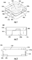
- FIG. 1 illustrates an isometric view of an inductor in partial transparency according to the invention
- FIG. 2 illustrates an end view of the inductor of FIG. 1 shown from a lead end
- FIG. 3 illustrates an end view of the inductor of FIG. 1 shown from a non-lead end
- FIG. 4A illustrates a view of the inductor of FIG. 1 shown from the top in partial transparency
- FIG. 4B illustrates a side view of inductor of FIG. 1 viewed from the lead edge
- FIG. 4C illustrates a side view of inductor of FIG. 1 viewed from the non-lead edge
- FIG. 5 illustrates schematically a method of making an inductor according to an embodiment of the present invention
- FIG. 6 illustrates a leadframe formed at the stamping step in the method of FIG. 5 ;
- FIG. 7 illustrates a top down perspective leadframe formed at the stamping step in the method of FIG. 5
- FIG. 8 illustrates a part formed at the pressing step in the method of FIG. 5 ;
- FIG. 9 illustrates a top down perspective of a part formed at the pressing step in the method of FIG. 5 ;
- FIG. 10 illustrates a part formed at the pressing step in the method of FIG. 5 ;
- FIG. 11A illustrates a top down perspective of a part formed at the pressing step in the method of FIG. 5 ;
- FIG. 11B illustrates a side perspective of a part formed at the pressing step in the method of FIG. 5 ;
- FIG. 12 illustrates a leadframe with embodiments of an inductor coil according to the invention
- FIG. 13 illustrates a top view of the leadframe and inductor coils of FIG. 12 ;
- FIG. 14 illustrates a leadframe with embodiments of an inductor coil according to the invention
- FIG. 15 illustrates a top view of a leadframe with embodiments of an inductor coil according to the invention
- FIG. 16 illustrates another embodiment of a leadframe and coil according to the present invention
- FIG. 17 illustrates a perspective view of an assembled inductor according to an embodiment of the present invention
- FIGS. 18A and B illustrate an assembled inductor according to the present invention
- FIG. 19 illustrates inductor shown with second body in see-through and core and body removed
- FIG. 20 illustrates a top view of a coil from an assembled inductor with other parts of the inductor 3100 removed;
- FIG. 21 illustrates a bottom view of a coil from an assembled inductor with other parts of the inductor 3100 removed;
- FIGS. 22A-B illustrates a body from an assembled inductor with other parts of the inductor removed
- FIG. 23 illustrates connections of insulated coils via welding and/or soldering.
- FIG. 1 shows an example of an inductor 3100 according to an embodiment described herein, including a shaped coil 3150 formed from a conductor, such as a metal plate, sheet or strip.
- a shaped coil 3150 may be shaped in a unique configuration that provides for increased efficiency and performance in a small volume and that is simple to manufacture.
- the coil 3150 and leads 3140 a and 3140 b are preferably initially formed by stamping a conductive sheet, such as a copper sheet, which may be flat and will produce a flat coil, as shown for example in FIG. 6 . It is appreciated that the surfaces of the coil 3150 may be somewhat or slightly rounded, bowed or curved based on the process used to form the coil 3150 , and the side edges may be rounded or curved.
- Acceptable metals used for forming the coil and leads may be copper, aluminum, platinum, or other metals for use as inductor coils as are known in the art.
- “flat” means “generally flat,” i.e., within normal manufacturing tolerances. It is appreciated that the flat surfaces of the coil 3150 may be somewhat or slightly rounded, bowed, curved or wavy based on the process used to form the coil 3150 , and the side edges may be somewhat or slightly rounded, bowed, curved or wavy, while still being considered to be “flat.”
- the stamped copper coil, leads and frame portions may be referred to collectively as a “leadframe.” Examples are shown in FIGS. 6-11 . Initially, such as during manufacturing, the shaped coil and leads may lie in the same plane. Each lead 3140 a and 3140 b will ultimately be bent around the inductor body, with a lead contact portion 3130 bent underneath the bottom of the inductor body.
- the leads 3140 a and 3140 b and coil 3150 are preferably formed as a unitary piece, without a weld.
- the coil 3150 comprises a serpentine or meandering coil provided as an “S” shaped coil or “S-coil,” when viewed from the top as oriented in the relevant Figures.
- the coil 3150 has a central portion 3151 crossing diagonally through the middle of the coil.
- a first curved portion C 1 has a first end 3152 extending from one of the leads 3140 b , and a second end 3153 curving around the center of the coil 3150 .
- a second curved portion C 2 has a first end 3155 extending from the other of the leads 3140 a , and a second end 3154 curving around the center of the coil 3150 in an opposite direction from the first curved portion C 1 .
- Each curved portion forms an arc encircling part of the center of the coil 3150 .
- the curved portions may each run along a circumferential path about the center.
- the coil 3150 may have a central portion 3151 that may be formed as a flat, straight strip, running from the second end 3153 of the first curved portion C 1 and across the center of the coil 3150 to the second end 3154 of the second curved portion C 2 .
- This central portion 3151 completes the “S” shape.
- This S-coil or “S” shape is illustrative of a preferred embodiment.
- Other configurations are also contemplated, as will be discussed in part below, including arc, Z-coil or N-coil configurations.
- a coil configuration that extends along a meandering path between leads, with a portion of the coil crossing the mid-line or central portion of the coil or an inductor body, would be considered to be a “serpentine” coil.
- an S-coil, Z-coil, N-coil, and other shaped coils having meandering paths traced from one lead to the other lead are considered to be “serpentine” coils.
- a serpentine coil may be distinguished from a “winding” coil formed from a wire that encircles a central portion of an inductor core, but does not have a portion crossing or traversing the central portion or a central line of an inductor core.
- a serpentine coil 3150 of the invention may have a first path P 1 extending toward a first direction from one side of the inductor toward the opposite side, such as extending from a side of the inductor including the lead 3140 b toward an opposite side of the inductor including the lead 3140 a .
- the first path P 1 is a curved or arced path curving away from a central portion of the coil.
- a second path P 2 continues from the first path P 1 and extends toward a second direction, crossing a central line L A of the coil.
- the second path P 2 slopes diagonally across the center and central line L A of the coil from the side where the first path P 1 ends back toward the side where the first path P 1 began, such as extending from a side of the inductor including the lead 3140 a back toward an opposite side of the inductor including the lead 3140 b .
- the second path P 2 may be a generally straight path along most of its length.
- a third path P 3 continues from the second path P 2 and extends in a third direction from one side of the inductor toward the opposite side, such as extending from a side of the inductor including the lead 3140 b toward an opposite side of the inductor including the lead 3140 a .
- the third path P 3 is a curved or arced path curving away from a central portion of the coil.
- the first and third directions are generally the same, while curving in opposite directions, and also both differ from the second direction.
- the combination of path P 1 , P 2 and P 3 is a preferably contiguous serpentine path, uninterrupted and formed from the same conductor.
- the first and third path P 1 and P 3 may trace curved paths, straight paths or combinations of curved and straight paths.
- an “N”-shaped coil may trace a first path P 1 that is generally straight from a first side of the inductor to an opposite side, a second path P 2 running diagonally across a center line L A back toward the first side, and a third path P 3 that is generally straight from a first side of the inductor to an opposite side along most of the lengths of those paths.
- the spaces or gaps are provided between the various portions of the coil, such as between the curved portion C 1 and the central portion 3151 , and between the curved portion C 2 and central portion 3151 .
- the spaces or gaps have a generally semi-circular shape, as shown in FIGS. 4A, 7 and 25 and 39 .
- the spaces or gaps In the “N”-shaped embodiment as shown in FIG. 16 , the spaces or gaps have a generally triangular shape. In a “Z”-shaped coil, the spaces or gaps would also have a generally triangular shape.
- the shape of the coil 3150 is designed to optimize the path length to fit the space available within the inductor while minimizing resistance and maximizing inductance.
- the shape may be designed to increase the ratio of the space used compared to the space available in the inductor body.
- coil 3150 is preferably flat and oriented essentially in a plane.
- the “S” shape optimizes the inductance and resistance values compared to other non-coil conductor configurations.
- a 1212 package size (approximately 0.12′′ ⁇ 0.12′′ ⁇ 0.04′′) with the S-coil may produce inductance values in the range of 0.05 uH at 2.2 m ⁇ .
- a 4040 package size (approximately 0.4′′ ⁇ 0.4′′ ⁇ 0.158′′) with the S-coil may produce inductance values in the range of 0.15 uH at 0.55 m ⁇ .
- the 1616 package size with the S-coil may produce inductance values of 0.075 uH and the 6767 package size with the S-coil may produce inductance values of 0.22 uH.
- a finished inductor 3100 includes an inductor body shown in partial transparency formed about, pressed over or otherwise housing the coils and at least parts of the leads, including a first body portion 3110 and a second body portion 3120 .
- a first body portion 3110 and a second body portion 3120 sandwich, are pressed around or otherwise house the shaped coil 3150 and parts of the leads 3140 a and 3140 b to form the finished inductor 3100 .
- inductor 3100 may be seen with the first body portion 3110 on the bottom and the second body portion 3120 on the top.
- first body portion 3110 and second body portion 3120 are shown as separate or discrete portions used to form the finished inductor 3100 , although a single, unitary overall body may be used. In alternative implementations, any number of body portions may be used.
- the body may be formed of a ferrous material.
- the body may comprise, for example, iron, metal alloys, or ferrite, combinations of those, or other materials known in the art of inductors and used to form such bodies.
- First body 3110 and second body portion 3120 may comprise a powdered iron or similar materials, as will be further discussed. Other acceptable materials as are known in the art of inductors may be used to form the body or body portions, such as known magnetic materials.
- a magnetic molding material may be used for the body, comprised of a powdered iron, a filler, a resin, and a lubricant, such as described in U.S. Pat. No. 6,198,375 (“Inductor coil structure”) and U.S. Pat. No. 6,204,744 (“High current, low profile inductor”). While it is contemplated that first body portion 3110 and second body portion 3120 are formed in similar fashion and of the same materials, first body portion 3110 and second body portion 3120 may be formed using different processes and from distinct materials, as are known in the art.
- the first body portion 3110 and second body portion 3120 surround the coil and parts of the leads, and may be pressed or over-molded around the coil 3150 , initially leaving exposed parts of the leads 3140 a and 3140 b until they are folded underneath first body portion 3110 as shown in their final state in the partially transparent examples of FIG. 4A-C .
- each lead 3140 a and 3140 b may run along sides of the first body portion 3110 as shown in FIG. 4B .
- Each lead 3140 a and 3140 b terminates with a contact portion 3130 bent underneath the first body portion 3110 as visible in FIG. 1 .
- a shelf 3160 may be formed by the portion of lead 3140 a that bends along an outer side of the inductor body 3110 .
- the shelf 3160 is formed adjacent where the lead meets the coil 3150 , which can also be seen in FIG. 3 .
- the shelf 3160 may transition to a diameter less than the other portions of the lead 3140 .
- This shelf 3160 allows for the lead thickness exiting the body to be smaller to improve the ability to form the part.
- This shelf 3160 allows additional room for the coil inside the body. It is appreciated that this shelf 3160 is not required in all circumstances, and an inductor or coil or leads according to the invention could be formed without such a shelf.
- the configuration of coil 3150 may include a coil cutout 3170 adjacent an inner side of the coil where the shelf 3160 transitions to the curved portions C 1 , C 2 .
- Coil cutout 3170 allows separation (space) between the lead and coil.
- FIG. 2 shows that the body of the inductor may include a first cutout 3180 or groove in the first body portion 3110 to provide access for placing the lead contact portion 3130 under and against the bottom 3111 of the outer surface of the first body portion 3110 .
- FIG. 3 shows that a second cutout 3190 or groove may also be provided in the first body portion 3110 to provide further access for placing the lead contact portion 3130 under and against the bottom 3111 of the outer surface of the first body portion 3110 .
- FIGS. 4A-C illustrate additional views of inductor 3100 .
- FIG. 4A illustrates a partially transparent view of the inductor 3100 , with the coil 3150 visible through the transparency.
- FIG. 4B illustrates a side view of inductor 3100 viewed from the lead 3140 a edge.
- FIG. 4C illustrates a side view of inductor 3100 viewed from the non-lead edge.
- coil 3150 may be shaped as an “S” or “Z,” depending on orientation.
- the “S” or “Z” shaped may also comprise the mirror-image of such shapes when viewed from the top as shown in the Figures.
- the orientation of coil 3150 may be rotated 180 degrees to form the other of an “S” or “Z” configuration.
- FIG. 5 depicts a method 3500 for making inductor 3100 .
- the inductor is produced by stamping to produce features that become leads and a coil between the leads in a desired shape.
- the stamping may be performed on flat sheets of copper to produce features which make up electrical leads, one on one side of the part and one on the other side of the part, and a coil joining the two leads formed in an “S” shape.
- the stamped S-coil inductor is a simple and cost effective way to produce consistent inductors with inductance lower than 1 uH.
- the stamped S-coil inductor is a simple and cost effective way to produce consistent inductors with a direct current resistance up to 80% lower than current high current, lower profile production methods in some instances.
- the sheets of copper may have leftover copper strips with progressive holes for alignment into manufacturing equipment, which are referred to as carrier strips or frame portions.
- the stamped copper sheets may be referred to as “leadframe.”
- pressed powder such as powdered iron
- a body is pressed into a body about the coil with the leads extending therefrom.
- the body may be pressed to form a desired shape with a body similar to an IHLP inductor.
- the iron core and leadframe may now be referred to as a “part.”
- the part is cured in an oven. This curing process binds the core together.
- the carrier strip is trimmed away from the leads on the leadframe.
- the leads are folded around the body of the inductor to form the lead contact portions at step 3550 .
- stamped coil and leads could also be assembled using other known core materials known to the art.
- FIGS. 6-7 collectively illustrate a leadframe 3600 formed at the stamping step (step 510 ) in method 3500 .
- FIG. 6 illustrates an isometric view of leadframe 3600 and
- FIG. 7 illustrates an overview of leadframe 3600 .
- FIGS. 6-7 illustrate leadframe 3600 including a two coil 3150 structure as part of the leadframe. It is appreciated that any number of coils may be formed in the manufacturing process along a leadframe, and two coils are shown for ease of illustration and understanding only.
- Leadframe 3600 includes a first frame portion 3620 and a second frame portion 3630 (also referred to as “carrier strips”) at the ends of the leads, and with the coil positioned centrally between the first frame portion 3620 and a second frame portion 3630 .
- the inductor assembly includes leads 3140 , and coil 3150 . Adjacent to lead 3140 a is a shelf 3160 .
- the coil 3150 includes a coil cutout 3170 .
- First frame portion 3620 includes an alignment hole pattern 3610 . This pattern 3610 enables alignment as part of the manufacturing process. For example, during pressing.
- FIGS. 8-11 illustrate a part 3800 of an inductor formed at the pressing step (step 3520 ) in the method discussed in FIG. 5 .
- FIG. 8 illustrates an isometric view of part 3800 formed at the pressing step depicting only the inner core 3115 surrounding the coil.
- FIG. 9 illustrates an overview of part 3800 shown in FIG. 8 .
- FIG. 10 illustrates an isometric view of part 3800 formed at the pressing step depicting one of the inductors with body 3110 , 3120 included and another where the body 3110 , 3120 is shown in partially transparent visual allowing the inner core 3115 and coil 3150 to be viewed.
- FIG. 11A illustrates part 3800 in an overview of part 3800 with the outer body 3125 in partial transparency to show positioning of inner core 3115 and coil 3150 .
- FIG. 11B illustrates provides a partially transparent side view of part 3800 from FIG. 10 .
- Part 3800 includes leadframe 3600 , which includes first frame portion 3620 and second frame portion 3630 on opposite ends of the leads 3140 a and 3140 b and coil 3150 .
- Adjacent to lead 3140 a is a shelf 3160 , indentation or step.
- On coil 3150 is a coil cutout 3170 .
- First frame portion 3620 includes an alignment hole pattern 3610 . This pattern 3610 enables alignment within the manufacturing process.
- part 3800 includes body 3125 pressed over the coil 3150 and a portion of leads 3140 , leaving exposed portions of the leads 3140 a and 3140 b and the first frame portion 3620 and second frame portion 3630 .
- Body 3125 may include first body portion 3110 and second body portion 3120 as described.
- Body 3125 may be formed from pressing a ferrite material around the coil 3150 .
- Body 3125 may be separate from an inner core 3115 or they may be formed together, such as a unitary part.
- the inner core can be formed in different ways: the material can be formed separately, typically from ferrite, and then laid on top of the coil and then the body can be pressed around it, or the inner core can be pressed around the coil separately, typically using some type of iron, and then the outer core can be pressed around the inner core using the same or different materials.
- the inner core could be used as the sole source of permeable material, or as the sole body of the device, without the outer core.
- the body 3125 may encase the inner core 3115 .
- a body 3125 could be formed as a unitary piece or combination with an inner core 3115 .
- the body may only be an inner core.
- FIGS. 10 and 11A and B show the inductor body 3125 , illustrating the body 3125 and inner core 3115 , with the body 3125 shown in transparency.
- the inner core 3115 may or may not be a separate part of the body 3125 , and is shown isolated for illustrative purposes in FIGS. 8 and 9 .
- the inner core 3115 is generally cylindrical, and includes a channel shaped to receive the central portion 3151 of the coil 3150 .
- the curved portions C 1 , C 2 of the coil 3150 surround the inner core 3115 , as shown ion FIG. 10 .
- the first body portion 3110 and second body portion 3120 When brought together, they may form or otherwise contain the inner core 3115 .
- an inductor may have multiple stacked coils, as shown in the examples of FIGS. 12-14 .
- FIG. 12 illustrates an isometric view of inductor 3100 with two coils. As depicted in FIG. 12 where coils are attached to a leadframe, a second coil 3150 b is aligned and adhered to, such as laminated to, a first coil 3150 a . In adhering the coils 3150 a , 3150 b together, solder may be used. This solder in addition to adhering and maintaining alignment provides an electrical connection between the first coil 3150 a and the second coil 3150 b .
- the leadframe for the second coil 3150 b may be removed for subsequent processing steps exposing a singular lead 3140 .
- FIG. 13 illustrates a top view of the multi-coil, multi-layered embodiment of FIG. 12 . From this view, only the second coil 3150 b may be seen.
- the leadframe associated with the second coil 3150 b has been removed exposing the lead 3140 a from the first coil 3150 a leadframe. If formed by aligning two leadframes, a boundary 3145 b or edge may be formed where the leadframe of the second coil 3150 b is removed.
- the coils may also be separated from each other within the body using insulation between each coil layer. This insulation may provide improved performance of the inductor in certain situations.
- the insulation may comprise KaptonTM, NylonTM, or TeflonTM, or other insulative materials as are known in the art.
- the coils may be connected on the ends using a method such as welding and/or soldering.
- FIG. 14 illustrates an inductor 3100 with a plurality of coils, showing a three-coil design.
- a first coil 3150 a is included in the leadframe and a second coil 3150 b is aligned and adhered to a top of the first coil 3150 a and a third coil 3150 c is aligned and adhered to a bottom of the first coil 3150 a .
- a solder 3232 may be used as shown in FIG. 23 . This solder in addition to adhering and maintaining alignment provides an electrical connection between the first coil 3150 a and the second coil 3150 b .
- the leadframe for the second coil 3150 b and the third coil 3150 c may each be removed for subsequent processing steps exposing a singular lead 3140 .
- the leadframe associated with the second coil 3150 b has been removed exposing the lead 3140 a from the first coil 3150 a leadframe.
- a boundary 3145 b is formed from the removal of the leadframe of the second coil 3150 b .
- the leadframe associated with the third coil 3150 c has been removed exposing the lead 3140 a from the first coil 3150 a leadframe.
- a boundary 3145 c is formed from the removal of the leadframe of the third coil 3150 c .
- the first coil 3150 a , second coil 3150 b and third coil 3150 c may or may not be separated by insulation 3231 as shown in FIG. 23 .
- FIG. 15 illustrates a formation of the coil with a reduced leadframe having only one carrier strip 3621 .
- a stamped “S” shaped coil 3150 may have the same elements as described in FIG. 1 .
- the “S” shaped coil 3150 includes a first lead 3140 a connected to the carrier strip 3621 , and a second lead 3140 b extending from an opposite side of the coil 3150 .
- FIG. 16 illustrates an alternate shape for an inductor coil.
- an “N” shaped coil 3159 (where the “N” is standing up relative to the length of the carrier strip 3561 ), is provided.
- the “N” shaped coil 3159 includes a first portion N 1 that connects with a second lead 3140 b , and a second portion N 1 that connects to a first lead 3140 a that connects to the carrier strip 3621 .
- the two portions N 1 and N 2 are connected by a central portion N 3 of the coil 3159 .
- the two portions N 1 and N 2 of FIG. 16 are generally straight compared to the curved portions C 1 and C 2 of FIG. 1 .
- the outer corners of the portions N 1 and N 2 where the portions bend of meet the leads 3140 a , 3140 b , curved away from the central portion N 3 of the coil.
- FIG. 17 illustrates a depiction of an assembled inductor 3100 according to the present invention.
- Inductor 3100 includes a first body 3110 and second body 3120 . Also shown is lead 3140 , including a step adjacent where the lead exits the body.
- FIGS. 18A and B illustrate an assembled inductor 3100 according to the present invention.
- FIG. 19 illustrates an inductor shown with the second body 3120 in partial transparency, and cut-away from the top.
- Coil 3150 is shown connecting leads 3140 a and 3140 b .
- Coil 3150 includes regions C 1 , C 2 with a cross-member 3151 .
- FIG. 20-21 illustrate coil 3150 from an assembled inductor 3100 (e.g., with the leads bent) with other parts of the inductor 3100 removed.
- FIG. 20 depicts an isometric view of coil 3150 from above and
- FIG. 21 depicts an isometric view of coil 3150 from below.
- Coil 3150 is shown connecting leads 3140 .
- Coil 3150 includes curved or arced regions or portions C 1 and C 2 with a cross-member or central portion 3151 .
- FIGS. 22A and B illustrate, in transparency, embodiments of a first body 3110 ( FIG. 22B ) and a second body 3120 ( FIG. 22A ) from an assembled inductor 3100 with other parts of the inductor 3100 removed.
- First body 3110 and second body 3120 includes an inner core recess 3221 and a channel recess 3222 for receiving or accommodating a separate inner core and a channel for the coil as described above.
- First body 3110 and second body 3120 could also form the inner core and include a channel for the coil as described above.
- the top of first body 3110 meets the bottom of second body 3120 to create the inner core 3221 recess and the channel recess 3222 .
- An inductor according to any of the embodiments discussed herein may be utilized in electronics applications, such as DC/DC converters, to achieve one or more of the following: low direct current resistance; tight tolerances on inductance and or direct current resistance; inductance below 1 uH; low profiles and high current; efficiency in circuits and/or in situations where similar products cannot meet electric current requirements.
- an inductor may be useful in DC/DC converters operating at 1 Mhz and above.
- the present invention provides for an inductor provided with a high current serpentine coil, such as an “S” shaped coil, with low direct current resistance.
- a high current serpentine coil such as an “S” shaped coil
- the design simplifies manufacturing by eliminating a welding process.
- the design reduces direct current resistance by eliminating a high resistance weld between the coil and the leads. This allows for inductors with inductance ratings below 1 uH to be produced consistently.
- the “S” shape for the coil optimizes inductance and resistance values compared to a similar stamped coil configuration and other non-coil configurations.
- the formed serpentine coil inductor such as a coil in the S-shape described herein, provides a simple and cost-effective way to produce consistent inductors and to produce inductors with direct current resistance up to 80% lower than comparable known inductors such as IHLP inductors.
Landscapes
- Engineering & Computer Science (AREA)
- Power Engineering (AREA)
- Manufacturing & Machinery (AREA)
- Microelectronics & Electronic Packaging (AREA)
- Coils Or Transformers For Communication (AREA)
- Coils Of Transformers For General Uses (AREA)
- Manufacturing Cores, Coils, And Magnets (AREA)
Abstract
Description
Claims (21)
Priority Applications (1)
| Application Number | Priority Date | Filing Date | Title |
|---|---|---|---|
| US16/289,109 US11049638B2 (en) | 2016-08-31 | 2019-02-28 | Inductor having high current coil with low direct current resistance |
Applications Claiming Priority (3)
| Application Number | Priority Date | Filing Date | Title |
|---|---|---|---|
| US201662382182P | 2016-08-31 | 2016-08-31 | |
| PCT/US2017/049332 WO2018045007A1 (en) | 2016-08-31 | 2017-08-30 | Inductor having high current coil with low direct current resistance |
| US16/289,109 US11049638B2 (en) | 2016-08-31 | 2019-02-28 | Inductor having high current coil with low direct current resistance |
Related Parent Applications (1)
| Application Number | Title | Priority Date | Filing Date |
|---|---|---|---|
| PCT/US2017/049332 Continuation WO2018045007A1 (en) | 2016-08-31 | 2017-08-30 | Inductor having high current coil with low direct current resistance |
Publications (2)
| Publication Number | Publication Date |
|---|---|
| US20200035413A1 US20200035413A1 (en) | 2020-01-30 |
| US11049638B2 true US11049638B2 (en) | 2021-06-29 |
Family
ID=61243190
Family Applications (4)
| Application Number | Title | Priority Date | Filing Date |
|---|---|---|---|
| US15/692,134 Active US10854367B2 (en) | 2016-08-31 | 2017-08-31 | Inductor having high current coil with low direct current resistance |
| US16/289,109 Active US11049638B2 (en) | 2016-08-31 | 2019-02-28 | Inductor having high current coil with low direct current resistance |
| US17/106,718 Active 2037-10-24 US11875926B2 (en) | 2016-08-31 | 2020-11-30 | Inductor having high current coil with low direct current resistance |
| US18/411,206 Pending US20240347254A1 (en) | 2016-08-31 | 2024-01-12 | Inductor having high current coil with low direct current resistance |
Family Applications Before (1)
| Application Number | Title | Priority Date | Filing Date |
|---|---|---|---|
| US15/692,134 Active US10854367B2 (en) | 2016-08-31 | 2017-08-31 | Inductor having high current coil with low direct current resistance |
Family Applications After (2)
| Application Number | Title | Priority Date | Filing Date |
|---|---|---|---|
| US17/106,718 Active 2037-10-24 US11875926B2 (en) | 2016-08-31 | 2020-11-30 | Inductor having high current coil with low direct current resistance |
| US18/411,206 Pending US20240347254A1 (en) | 2016-08-31 | 2024-01-12 | Inductor having high current coil with low direct current resistance |
Country Status (9)
| Country | Link |
|---|---|
| US (4) | US10854367B2 (en) |
| EP (1) | EP3507816A4 (en) |
| JP (2) | JP7160438B2 (en) |
| KR (2) | KR102571361B1 (en) |
| CN (2) | CN109891530B (en) |
| CA (1) | CA3035547A1 (en) |
| MX (1) | MX2019002447A (en) |
| TW (2) | TWI757330B (en) |
| WO (1) | WO2018045007A1 (en) |
Cited By (3)
| Publication number | Priority date | Publication date | Assignee | Title |
|---|---|---|---|---|
| US11744021B2 (en) | 2022-01-21 | 2023-08-29 | Analog Devices, Inc. | Electronic assembly |
| US11875926B2 (en) | 2016-08-31 | 2024-01-16 | Vishay Dale Electronics, Llc | Inductor having high current coil with low direct current resistance |
| USD1077746S1 (en) | 2021-03-01 | 2025-06-03 | Vishay Dale Electronics, Llc | Inductor package |
Families Citing this family (23)
| Publication number | Priority date | Publication date | Assignee | Title |
|---|---|---|---|---|
| JP6561953B2 (en) * | 2016-09-21 | 2019-08-21 | 株式会社オートネットワーク技術研究所 | Magnetic core and reactor |
| JP7471770B2 (en) * | 2017-12-28 | 2024-04-22 | 新光電気工業株式会社 | Inductor and method for manufacturing the inductor |
| JP7229706B2 (en) * | 2018-09-05 | 2023-02-28 | 新光電気工業株式会社 | Inductor and its manufacturing method |
| JP7628390B2 (en) * | 2019-07-18 | 2025-02-10 | 株式会社トーキン | Inductors |
| US20210035730A1 (en) * | 2019-07-31 | 2021-02-04 | Murata Manufacturing Co., Ltd. | Inductor |
| JP2021027203A (en) * | 2019-08-06 | 2021-02-22 | 株式会社村田製作所 | Inductor |
| JP7354715B2 (en) * | 2019-09-19 | 2023-10-03 | Tdk株式会社 | inductor element |
| JP7287216B2 (en) * | 2019-09-24 | 2023-06-06 | Tdk株式会社 | coil structure |
| JP7111086B2 (en) | 2019-11-01 | 2022-08-02 | 株式会社村田製作所 | inductor |
| CN110911145A (en) * | 2019-12-02 | 2020-03-24 | 旺诠科技(昆山)有限公司 | Method for manufacturing inductive elements in batches |
| JP7472490B2 (en) * | 2019-12-24 | 2024-04-23 | Tdk株式会社 | Coil device |
| US20210280361A1 (en) * | 2020-03-03 | 2021-09-09 | Vishay Dale Electronics, Llc | Inductor with preformed termination and method and assembly for making the same |
| WO2021205817A1 (en) * | 2020-04-07 | 2021-10-14 | 株式会社村田製作所 | Coil structure and inductor element |
| CN112509783B (en) * | 2020-08-09 | 2022-04-12 | 华为数字能源技术有限公司 | Power inductor and preparation method thereof, and system-in-package module |
| KR102871143B1 (en) * | 2020-11-20 | 2025-10-16 | 현대모비스 주식회사 | EMC filter for electromagnetic regulation of converter and method for fabricating thereof |
| JP2023552401A (en) * | 2020-12-04 | 2023-12-15 | 横店集団東磁股▲ふん▼有限公司 | Integrated co-firing inductor and its manufacturing method |
| JP7585785B2 (en) * | 2020-12-29 | 2024-11-19 | セイコーエプソン株式会社 | Liquid ejection device |
| JP2022104713A (en) * | 2020-12-29 | 2022-07-11 | セイコーエプソン株式会社 | Liquid discharge device |
| US11948724B2 (en) * | 2021-06-18 | 2024-04-02 | Vishay Dale Electronics, Llc | Method for making a multi-thickness electro-magnetic device |
| FR3130082A1 (en) * | 2021-12-07 | 2023-06-09 | Valeo Systemes De Controle Moteur | Electric component for electric machine |
| US12542356B2 (en) * | 2022-03-25 | 2026-02-03 | Intel Corporation | Low radiation high symmetry inductor |
| TWI832230B (en) * | 2022-05-05 | 2024-02-11 | 聯寶電子股份有限公司 | Tlvr transformer |
| WO2025182251A1 (en) * | 2024-02-29 | 2025-09-04 | 株式会社村田製作所 | Coil component and metal plate |
Citations (226)
| Publication number | Priority date | Publication date | Assignee | Title |
|---|---|---|---|---|
| US1085437A (en) | 1912-02-06 | 1914-01-27 | Friedrich August Volkmar Klopfer | Manufacture of milled soap. |
| US2497516A (en) | 1944-04-22 | 1950-02-14 | Metropolitan Eng Co | Electrical winding |
| US2889525A (en) | 1954-12-13 | 1959-06-02 | Central Transformer Corp | Three-phase core for transformers |
| US3169234A (en) | 1959-08-17 | 1965-02-09 | Coileraft Inc | Coil form, and coils and transformers mounted thereto |
| GB1071469A (en) | 1964-01-10 | 1967-06-07 | Comp Generale Electricite | High voltage winding |
| US3958328A (en) | 1975-06-02 | 1976-05-25 | Essex International, Inc. | Method of making a transformer coil assembly |
| US4180450A (en) | 1978-08-21 | 1979-12-25 | Vac-Tec Systems, Inc. | Planar magnetron sputtering device |
| US4223360A (en) | 1973-04-13 | 1980-09-16 | Data Recording Instrument Company, Ltd. | Magnetic recording transducers |
| US4413161A (en) | 1980-02-09 | 1983-11-01 | Nippon Gakki Seizo Kabushiki Kaisha | Electro-acoustic transducer |
| US4901048A (en) | 1985-06-10 | 1990-02-13 | Williamson Windings Inc. | Magnetic core multiple tap or windings devices |
| US5010314A (en) | 1990-03-30 | 1991-04-23 | Multisource Technology Corp. | Low-profile planar transformer for use in off-line switching power supplies |
| JPH03171703A (en) | 1989-11-30 | 1991-07-25 | Tokin Corp | Transformer |
| JPH0459396A (en) | 1990-06-29 | 1992-02-26 | Yoshikazu Kimura | Production of information communication body and material thereof |
| JPH04129206A (en) | 1990-09-19 | 1992-04-30 | Toshiba Corp | Thin type transformer |
| US5126715A (en) | 1990-07-02 | 1992-06-30 | General Electric Company | Low-profile multi-pole conductive film transformer |
| US5245307A (en) * | 1989-04-18 | 1993-09-14 | Institut Dr. Friedrich Forster Pruferatebau Gmbh & Co. Kg | Search coil assembly for electrically conductive object detection |
| JPH05258959A (en) | 1992-03-10 | 1993-10-08 | Mitsubishi Electric Corp | Signal discriminator |
| EP0606973A1 (en) | 1993-01-15 | 1994-07-20 | General Electric Company | Electromagnetic pump stator coil |
| JPH0655211U (en) | 1993-01-09 | 1994-07-26 | 東光株式会社 | Noise filter |
| JPH06283338A (en) | 1993-03-26 | 1994-10-07 | Matsushita Electric Ind Co Ltd | Inductance parts and their manufacture |
| JPH07245217A (en) | 1994-03-03 | 1995-09-19 | Tdk Corp | Inductance element and coil for it |
| US5451914A (en) | 1994-07-05 | 1995-09-19 | Motorola, Inc. | Multi-layer radio frequency transformer |
| US5481238A (en) | 1994-04-19 | 1996-01-02 | Argus Technologies Ltd. | Compound inductors for use in switching regulators |
| JPH09306757A (en) | 1996-05-14 | 1997-11-28 | Sumitomo Special Metals Co Ltd | Low profile coil and magnetic product |
| EP0662699B1 (en) | 1994-01-10 | 1998-05-06 | Hughes Aircraft Company | Charging system, and method of making a charging system |
| US5773886A (en) | 1993-07-15 | 1998-06-30 | Lsi Logic Corporation | System having stackable heat sink structures |
| US5801432A (en) | 1992-06-04 | 1998-09-01 | Lsi Logic Corporation | Electronic system using multi-layer tab tape semiconductor device having distinct signal, power and ground planes |
| US5821624A (en) | 1989-08-28 | 1998-10-13 | Lsi Logic Corporation | Semiconductor device assembly techniques using preformed planar structures |
| US5844451A (en) * | 1994-02-25 | 1998-12-01 | Murphy; Michael T. | Circuit element having at least two physically separated coil-layers |
| US5888848A (en) | 1995-04-27 | 1999-03-30 | Imphy S.A. (Societe Anonyme) | Connection leads for an electronic component |
| US5912609A (en) | 1996-07-01 | 1999-06-15 | Tdk Corporation | Pot-core components for planar mounting |
| US5913551A (en) | 1994-07-20 | 1999-06-22 | Matsushita Electric Industrial Co., Ltd. | Method of producing an inductor |
| US5917396A (en) | 1997-08-04 | 1999-06-29 | Halser, Iii; Joseph G. | Wideband audio output transformer with high frequency balanced winding |
| US5949321A (en) | 1996-08-05 | 1999-09-07 | International Power Devices, Inc. | Planar transformer |
| JPH11340060A (en) | 1998-05-22 | 1999-12-10 | Toko Inc | Inverter transformer |
| JP2000021656A (en) | 1998-06-26 | 2000-01-21 | Toko Inc | Inverter transformer |
| US6026311A (en) | 1993-05-28 | 2000-02-15 | Superconductor Technologies, Inc. | High temperature superconducting structures and methods for high Q, reduced intermodulation resonators and filters |
| JP2000091133A (en) | 1998-09-10 | 2000-03-31 | Oki Electric Ind Co Ltd | Terminal structure of transformer and forming method of terminal |
| US6060976A (en) | 1996-01-30 | 2000-05-09 | Alps Electric Co., Ltd. | Plane transformer |
| US6078502A (en) | 1996-04-01 | 2000-06-20 | Lsi Logic Corporation | System having heat dissipating leadframes |
| US6081416A (en) | 1998-05-28 | 2000-06-27 | Trinh; Hung | Lead frames for mounting ceramic electronic parts, particularly ceramic capacitors, where the coefficient of thermal expansion of the lead frame is less than that of the ceramic |
| US6087922A (en) | 1998-03-04 | 2000-07-11 | Astec International Limited | Folded foil transformer construction |
| US6204744B1 (en) | 1995-07-18 | 2001-03-20 | Vishay Dale Electronics, Inc. | High current, low profile inductor |
| EP1091369A2 (en) | 1999-10-07 | 2001-04-11 | Lucent Technologies Inc. | Low profile transformer and method for making a low profile transformer |
| US6222437B1 (en) | 1998-05-11 | 2001-04-24 | Nidec America Corporation | Surface mounted magnetic components having sheet material windings and a power supply including such components |
| US6236297B1 (en) | 1998-07-08 | 2001-05-22 | Winbond Electronics Corp. | Combinational inductor |
| US6255725B1 (en) | 1998-05-28 | 2001-07-03 | Shinko Electric Industries Co., Ltd. | IC card and plane coil for IC card |
| US6317965B1 (en) | 1997-06-10 | 2001-11-20 | Fuji Electric Co., Ltd. | Noise-cut filter for power converter |
| US20020011914A1 (en) | 2000-05-22 | 2002-01-31 | Takeyoshi Ikeura | Transformer |
| US6351033B1 (en) | 1999-10-06 | 2002-02-26 | Agere Systems Guardian Corp. | Multifunction lead frame and integrated circuit package incorporating the same |
| US20020040077A1 (en) | 1998-11-23 | 2002-04-04 | Hoeganaes Corporation | Methods of making and using annealable insulated metal-based powder particles |
| US6392525B1 (en) | 1998-12-28 | 2002-05-21 | Matsushita Electric Industrial Co., Ltd. | Magnetic element and method of manufacturing the same |
| US6409859B1 (en) | 1998-06-30 | 2002-06-25 | Amerasia International Technology, Inc. | Method of making a laminated adhesive lid, as for an Electronic device |
| US6438000B1 (en) | 1999-04-27 | 2002-08-20 | Fuji Electric Co., Ltd. | Noise-cut filter |
| US20020130752A1 (en) | 1998-02-27 | 2002-09-19 | Tdk Corporation | Pot-core components for planar mounting |
| US6476689B1 (en) | 1999-09-21 | 2002-11-05 | Murata Manufacturing Co., Ltd. | LC filter with capacitor electrode plate not interfering with flux of two coils |
| US20030016112A1 (en) | 2001-06-21 | 2003-01-23 | Davide Brocchi | Inductive component made with circular development planar windings |
| US6546184B2 (en) | 1997-08-29 | 2003-04-08 | Matsushita Electric Industrial Co., Ltd | Still picture player |
| US20030141952A1 (en) * | 2002-01-31 | 2003-07-31 | Tdk Corporation | Coil-embedded dust core and method for manufacturing the same, and coil and method for manufacturing the same |
| US20030178694A1 (en) | 2000-08-04 | 2003-09-25 | Frederic Lemaire | Integrated inductor |
| JP2003309024A (en) | 2002-04-16 | 2003-10-31 | Tdk Corp | Coil encapsulating magnetic component and method of manufacturing the same |
| JP2004022814A (en) | 2002-06-17 | 2004-01-22 | Alps Electric Co Ltd | Magnetic element, inductor and transformer |
| US20040017276A1 (en) | 2002-07-25 | 2004-01-29 | Meng-Feng Chen | Inductor module including plural inductor winding sections connected to a common contact and wound on a common inductor core |
| US6713162B2 (en) | 2000-05-31 | 2004-03-30 | Tdk Corporation | Electronic parts |
| US20040061584A1 (en) | 2000-03-21 | 2004-04-01 | Darmann Francis Anthony | Superconductiing transformer |
| US6723775B2 (en) | 2000-09-14 | 2004-04-20 | Rohm And Haas Company | Method for preparing graft copolymers and compositions produced therefrom |
| US6734074B2 (en) | 2002-01-24 | 2004-05-11 | Industrial Technology Research Institute | Micro fabrication with vortex shaped spirally topographically tapered spirally patterned conductor layer and method for fabrication thereof |
| US6765284B2 (en) | 2002-02-25 | 2004-07-20 | Rf Micro Devices, Inc. | Leadframe inductors |
| US6774757B2 (en) | 2002-05-27 | 2004-08-10 | Sansha Electric Manufacturing Company, Limited | Coil |
| JP2004266120A (en) | 2003-03-03 | 2004-09-24 | Matsushita Electric Ind Co Ltd | Choke coil and electronic device using the same |
| US20040232982A1 (en) | 2002-07-19 | 2004-11-25 | Ikuroh Ichitsubo | RF front-end module for wireless communication devices |
| US20040245232A1 (en) | 2003-06-04 | 2004-12-09 | Ihde Jeffrey R. | Wire feeder operable with lower mininum input voltage requirement |
| US20050012581A1 (en) * | 2003-06-12 | 2005-01-20 | Nec Tokin Corporation | Coil component and fabricaiton method of the same |
| US20050030141A1 (en) | 1996-07-29 | 2005-02-10 | Iap Research, Inc. | Apparatus and method for making an electrical component |
| US6869238B2 (en) | 2002-11-26 | 2005-03-22 | Fuji Xerox Co., Ltd. | Printing control program, printing control system, and printing control method |
| US6879238B2 (en) | 2003-05-28 | 2005-04-12 | Cyntec Company | Configuration and method for manufacturing compact high current inductor coil |
| US6879235B2 (en) | 2002-04-30 | 2005-04-12 | Koito Manufacturing Co., Ltd. | Transformer |
| US6888435B2 (en) | 2000-04-28 | 2005-05-03 | Matsushita Electric Industrial Co., Ltd. | Composite magnetic body, and magnetic element and method of manufacturing the same |
| US6933895B2 (en) | 2003-02-14 | 2005-08-23 | E-Tenna Corporation | Narrow reactive edge treatments and method for fabrication |
| US6940154B2 (en) | 2002-06-24 | 2005-09-06 | Asat Limited | Integrated circuit package and method of manufacturing the integrated circuit package |
| CN1677581A (en) | 2004-04-01 | 2005-10-05 | 乾坤科技股份有限公司 | Novel coil and method of manufacturing the same |
| US6965517B2 (en) | 2002-07-22 | 2005-11-15 | C&D/Charter Holdings, Inc. | Component substrate for a printed circuit board and method of assembyling the substrate and the circuit board |
| US20050273938A1 (en) | 2004-06-09 | 2005-12-15 | The Coleman Company, Inc. | Airbed utilizing extruded coils |
| US20060001517A1 (en) | 2004-07-02 | 2006-01-05 | Cheng Chang M | High current inductor and the manufacturing method |
| JP2006505142A (en) | 2002-11-01 | 2006-02-09 | メトグラス・インコーポレーテッド | Inductive device made of bulk amorphous metal |
| US6998952B2 (en) | 2003-12-05 | 2006-02-14 | Freescale Semiconductor, Inc. | Inductive device including bond wires |
| US7023313B2 (en) | 2003-07-16 | 2006-04-04 | Marvell World Trade Ltd. | Power inductor with reduced DC current saturation |
| US7034645B2 (en) | 1999-03-16 | 2006-04-25 | Vishay Dale Electronics, Inc. | Inductor coil and method for making same |
| US7046492B2 (en) | 1997-02-03 | 2006-05-16 | Abb Ab | Power transformer/inductor |
| US20060113645A1 (en) | 2001-08-28 | 2006-06-01 | Tessera, Inc. | Microelectronic assemblies incorporating inductors |
| US20060132272A1 (en) | 2004-11-30 | 2006-06-22 | Tdk Corporation | Transformer |
| US7126443B2 (en) | 2003-03-28 | 2006-10-24 | M/A-Com, Eurotec, B.V. | Increasing performance of planar inductors used in broadband applications |
| US7176506B2 (en) | 2001-08-28 | 2007-02-13 | Tessera, Inc. | High frequency chip packages with connecting elements |
| US20070052510A1 (en) | 2005-09-07 | 2007-03-08 | Yonezawa Electric Wire Co., Ltd. | Inductance device and manufacturing method thereof |
| US7192809B2 (en) | 2005-02-18 | 2007-03-20 | Texas Instruments Incorporated | Low cost method to produce high volume lead frames |
| US7218197B2 (en) | 2003-07-16 | 2007-05-15 | Marvell World Trade Ltd. | Power inductor with reduced DC current saturation |
| US7221251B2 (en) | 2005-03-22 | 2007-05-22 | Acutechnology Semiconductor | Air core inductive element on printed circuit board for use in switching power conversion circuitries |
| US20070166554A1 (en) | 2006-01-18 | 2007-07-19 | Ruchert Brian D | Thermal interconnect and interface systems, methods of production and uses thereof |
| US20070186407A1 (en) | 1995-07-18 | 2007-08-16 | Vishay Dale Electronics, Inc. | Method for making a high current low profile inductor |
| US20070247268A1 (en) | 2006-03-17 | 2007-10-25 | Yoichi Oya | Inductor element and method for production thereof, and semiconductor module with inductor element |
| US7289329B2 (en) | 2004-06-04 | 2007-10-30 | Siemens Vdo Automotive Corporation | Integration of planar transformer and/or planar inductor with power switches in power converter |
| US20070252669A1 (en) * | 2006-04-26 | 2007-11-01 | Vishay Dale Electronics, Inc. | Flux channeled, high current inductor |
| US7292128B2 (en) | 2002-12-19 | 2007-11-06 | Cooper Technologies Company | Gapped core structure for magnetic components |
| US20070257759A1 (en) | 2005-11-04 | 2007-11-08 | Delta Electronics, Inc. | Noise filter and manufacturing method thereof |
| US7295448B2 (en) | 2004-06-04 | 2007-11-13 | Siemens Vdo Automotive Corporation | Interleaved power converter |
| US7294587B2 (en) | 2001-10-18 | 2007-11-13 | Matsushita Electric Industrial Co., Ltd. | Component built-in module and method for producing the same |
| US7317373B2 (en) | 2005-08-18 | 2008-01-08 | Delta Electronics, Inc. | Inductor |
| US20080029879A1 (en) | 2006-03-01 | 2008-02-07 | Tessera, Inc. | Structure and method of making lidded chips |
| US7339451B2 (en) | 2004-09-08 | 2008-03-04 | Cyntec Co., Ltd. | Inductor |
| EP1933340A1 (en) | 2005-09-08 | 2008-06-18 | Sumida Corporation | Coil device, composite coil device and transformer device |
| US20080150670A1 (en) | 2006-12-20 | 2008-06-26 | Samsung Electronics Co., Ltd. | Multi-layered symmetric helical inductor |
| US7392581B2 (en) | 2004-11-16 | 2008-07-01 | Sumida Corporation | Method for manufacturing a magnetic element |
| TWI299504B (en) | 2003-03-25 | 2008-08-01 | Cyntec Co Ltd | |
| US7456722B1 (en) | 2006-12-15 | 2008-11-25 | The United States Of America As Represented By The Secretary Of The Navy | Programmable microtransformer |
| US7460002B2 (en) | 2005-06-09 | 2008-12-02 | Alexander Estrov | Terminal system for planar magnetics assembly |
| US20080303606A1 (en) | 2007-06-08 | 2008-12-11 | Stats Chippac, Ltd. | Miniaturized Wide-Band Baluns for RF Applications |
| US7469469B2 (en) | 2002-09-13 | 2008-12-30 | Panasonic Corporation | Coil component and method of producing the same |
| US7489219B2 (en) | 2003-07-16 | 2009-02-10 | Marvell World Trade Ltd. | Power inductor with reduced DC current saturation |
| US20090057822A1 (en) | 2007-09-05 | 2009-03-05 | Yenting Wen | Semiconductor component and method of manufacture |
| US20090115562A1 (en) | 2007-11-06 | 2009-05-07 | Via Technologies, Inc. | Spiral inductor |
| US7540747B2 (en) | 2005-04-29 | 2009-06-02 | Finisar Corporation | Molded lead frame connector with one or more passive components |
| US7545026B2 (en) | 2004-07-13 | 2009-06-09 | Nxp B.V. | Electronic device comprising an integrated circuit |
| US7567163B2 (en) | 2004-08-31 | 2009-07-28 | Pulse Engineering, Inc. | Precision inductive devices and methods |
| JP2009224815A (en) | 2009-07-07 | 2009-10-01 | Sumida Corporation | Anti-magnetic type thin transformer |
| CN101578671A (en) | 2007-11-21 | 2009-11-11 | 松下电器产业株式会社 | Coil component |
| US20100007453A1 (en) | 2008-07-11 | 2010-01-14 | Yipeng Yan | Surface mount magnetic components and methods of manufacturing the same |
| US20100007452A1 (en) | 2006-08-28 | 2010-01-14 | Abb Technology Ltd. | High voltage transformer with a shield ring. a shield ring and a method of manufacture same |
| US7667565B2 (en) | 2004-09-08 | 2010-02-23 | Cyntec Co., Ltd. | Current measurement using inductor coil with compact configuration and low TCR alloys |
| US7675396B2 (en) | 2007-09-28 | 2010-03-09 | Cyntec Co., Ltd. | Inductor and manufacture method thereof |
| US20100060401A1 (en) | 2008-09-09 | 2010-03-11 | Hon Hai Precision Industry Co., Ltd. | Inductor and inductor coil |
| US7705508B2 (en) | 2006-05-10 | 2010-04-27 | Pratt & Whitney Canada Crop. | Cooled conductor coil for an electric machine and method |
| US20100123541A1 (en) | 2008-11-14 | 2010-05-20 | Denso Corporation | Reactor and method of producing the reactor |
| US7736951B2 (en) | 2007-03-15 | 2010-06-15 | Semiconductor Components Industries, L.L.C. | Circuit component and method of manufacture |
| US20100171579A1 (en) | 2008-07-29 | 2010-07-08 | Cooper Technologies Company | Magnetic electrical device |
| US7786834B2 (en) | 2007-11-15 | 2010-08-31 | Taiyo Yuden Co., Ltd. | Inductor and its manufacturing method |
| US7791445B2 (en) | 2006-09-12 | 2010-09-07 | Cooper Technologies Company | Low profile layered coil and cores for magnetic components |
| US20100271161A1 (en) | 2008-07-11 | 2010-10-28 | Yipeng Yan | Magnetic components and methods of manufacturing the same |
| US7825502B2 (en) | 2008-01-09 | 2010-11-02 | Fairchild Semiconductor Corporation | Semiconductor die packages having overlapping dice, system using the same, and methods of making the same |
| WO2010129352A1 (en) | 2009-05-04 | 2010-11-11 | Cooper Technologies Company | Magnetic component assembly |
| US20100314728A1 (en) | 2009-06-16 | 2010-12-16 | Tung Lok Li | Ic package having an inductor etched into a leadframe thereof |
| US7872350B2 (en) | 2007-04-10 | 2011-01-18 | Qimonda Ag | Multi-chip module |
| JP2011054811A (en) | 2009-09-03 | 2011-03-17 | Panasonic Corp | Coil component and manufacturing method thereof |
| US7915993B2 (en) | 2004-09-08 | 2011-03-29 | Cyntec Co., Ltd. | Inductor |
| US7920043B2 (en) | 2005-10-27 | 2011-04-05 | Kabushiki Kaisha Toshiba | Planar magnetic device and power supply IC package using same |
| CN102044327A (en) | 2009-10-19 | 2011-05-04 | 富士电子工业株式会社 | Thin type transformer for high-frequency induction heating |
| US7999650B2 (en) | 2005-11-30 | 2011-08-16 | Ryutaro Mori | Coil device |
| JP4768383B2 (en) * | 2004-10-19 | 2011-09-07 | 三星モバイルディスプレイ株式會社 | Driving method of stereoscopic image display device |
| US20110227690A1 (en) | 2009-06-30 | 2011-09-22 | Sumitomo Electric Industries, Ltd. | Soft magnetic material, compact, dust core, electromagnetic component, method of producing soft magnetic material, and method of producing dust core |
| US20110260825A1 (en) | 2006-09-12 | 2011-10-27 | Frank Anthony Doljack | Laminated magnetic component and manufacture with soft magnetic powder polymer composite sheets |
| US20110273257A1 (en) | 2010-01-14 | 2011-11-10 | Tdk-Lambda Corporation | Edgewise coil and inductor |
| US8080865B2 (en) | 2007-05-11 | 2011-12-20 | Intersil Americas, Inc. | RF-coupled digital isolator |
| US8097934B1 (en) | 2007-09-27 | 2012-01-17 | National Semiconductor Corporation | Delamination resistant device package having low moisture sensitivity |
| US20120049334A1 (en) | 2010-08-27 | 2012-03-01 | Stats Chippac, Ltd. | Semiconductor Device and Method of Forming Leadframe as Vertical Interconnect Structure Between Stacked Semiconductor Die |
| CN102376438A (en) | 2010-07-02 | 2012-03-14 | 三星电机株式会社 | Transformer |
| US8164408B2 (en) | 2009-09-02 | 2012-04-24 | Samsung Electro-Mechanics Co., Ltd. | Planar transformer |
| JP2012104724A (en) | 2010-11-12 | 2012-05-31 | Panasonic Corp | Inductor component |
| US20120176214A1 (en) | 2011-01-07 | 2012-07-12 | Wurth Electronics Midcom Inc. | Flatwire planar transformer |
| US20120216392A1 (en) | 2011-02-26 | 2012-08-30 | Fan Tso-Ho | Method for making a shielded inductor involving an injection-molding technique |
| US8279037B2 (en) | 2008-07-11 | 2012-10-02 | Cooper Technologies Company | Magnetic components and methods of manufacturing the same |
| EP2518740A1 (en) | 2009-12-25 | 2012-10-31 | Tamura Corporation | Reactor and method for producing same |
| US20120273932A1 (en) | 2011-04-29 | 2012-11-01 | Huawei Technologies Co., Ltd. | Power supply module and packaging and integrating method thereof |
| US8310332B2 (en) | 2008-10-08 | 2012-11-13 | Cooper Technologies Company | High current amorphous powder core inductor |
| CN102822913A (en) | 2010-03-26 | 2012-12-12 | 日立粉末冶金株式会社 | Dust core and method for producing same |
| US8350659B2 (en) | 2009-10-16 | 2013-01-08 | Crane Electronics, Inc. | Transformer with concentric windings and method of manufacture of same |
| US8466764B2 (en) | 2006-09-12 | 2013-06-18 | Cooper Technologies Company | Low profile layered coil and cores for magnetic components |
| US20130181803A1 (en) | 2012-01-16 | 2013-07-18 | Telefonaktiebolaget Lm Ericsson (Publ) | Wideband multilayer transmission line transformer |
| US20130249546A1 (en) | 2012-03-20 | 2013-09-26 | Allegro Microsystems, Llc | Integrated circuit package having a split lead frame |
| US20130273692A1 (en) | 2009-03-06 | 2013-10-17 | Utac Hong Kong Limited | Leadless array plastic package with various ic packaging configurations |
| US20130278571A1 (en) | 2012-04-18 | 2013-10-24 | Lg Display Co., Ltd. | Flat panel display device |
| US20130307117A1 (en) | 2012-05-18 | 2013-11-21 | Texas Instruments Incorporated | Structure and Method for Inductors Integrated into Semiconductor Device Packages |
| US20140008974A1 (en) | 2011-03-29 | 2014-01-09 | Sony Corporation | Electric power feed apparatus, electric power feed system, and electronic apparatus |
| US8659379B2 (en) | 2008-07-11 | 2014-02-25 | Cooper Technologies Company | Magnetic components and methods of manufacturing the same |
| CN103680861A (en) | 2013-11-27 | 2014-03-26 | 东莞普思电子有限公司 | Flat coil inductor, flat coil and manufacture method of flat coil |
| US8695209B2 (en) | 2009-04-10 | 2014-04-15 | Toko, Inc. | Method of producing a surface-mount inductor |
| US8707547B2 (en) | 2012-07-12 | 2014-04-29 | Inpaq Technology Co., Ltd. | Method for fabricating a lead-frameless power inductor |
| US20140125441A1 (en) | 2011-04-15 | 2014-05-08 | An Hui Qian En Intelligent Technology Company Limited | Large-current transformer for electronic round power meter and method of making |
| US20140210062A1 (en) | 2013-01-28 | 2014-07-31 | Texas Instruments Incorporated | Leadframe-Based Semiconductor Package Having Terminals on Top and Bottom Surfaces |
| US20140210584A1 (en) | 2013-01-25 | 2014-07-31 | Vishay Dale Electronics, Inc. | Low profile high current composite transformer |
| US20140302718A1 (en) | 2010-05-21 | 2014-10-09 | Amphenol Corporation | Electrical connector incorporating circuit elements |
| US20140320124A1 (en) | 2013-04-26 | 2014-10-30 | Allegro Microsystems, Llc | Integrated circuit package having a split lead frame and a magnet |
| US20140361423A1 (en) | 2011-06-03 | 2014-12-11 | Stats Chippac, Ltd. | Semiconductor Device and Method of Using Leadframe Bodies to Form Openings Through Encapsulant for Vertical Interconnect of Semiconductor Die |
| US8910369B2 (en) | 2011-09-28 | 2014-12-16 | Texas Instruments Incorporated | Fabricating a power supply converter with load inductor structured as heat sink |
| US8916408B2 (en) | 2009-12-31 | 2014-12-23 | Texas Instruments Incorporated | Leadframe-based premolded package having air channel for microelectromechanical system (MEMS) device |
| US8916421B2 (en) | 2011-08-31 | 2014-12-23 | Freescale Semiconductor, Inc. | Semiconductor device packaging having pre-encapsulation through via formation using lead frames with attached signal conduits |
| CN104247220A (en) | 2012-04-07 | 2014-12-24 | 特劳戈特·韦勒 | Method for manufacturing rotating electrical machines |
| US8927342B2 (en) | 2008-10-13 | 2015-01-06 | Tyco Electronics Amp Gmbh | Leadframe for electronic components |
| US8941457B2 (en) | 2006-09-12 | 2015-01-27 | Cooper Technologies Company | Miniature power inductor and methods of manufacture |
| US8998454B2 (en) | 2013-03-15 | 2015-04-07 | Sumitomo Electric Printed Circuits, Inc. | Flexible electronic assembly and method of manufacturing the same |
| US9001524B1 (en) | 2011-08-01 | 2015-04-07 | Maxim Integrated Products, Inc. | Switch-mode power conversion IC package with wrap-around magnetic structure |
| US9029741B2 (en) | 2005-03-28 | 2015-05-12 | Tyco Electronics Corporation | Surface mount multi-layer electrical circuit protection device with active element between PPTC layers |
| CN104685587A (en) | 2012-12-21 | 2015-06-03 | 丰田自动车株式会社 | Reactor and manufacturing method of the same |
| US20150214198A1 (en) | 2014-01-29 | 2015-07-30 | Texas Instruments Incorporated | Stacked semiconductor system having interposer of half-etched and molded sheet metal |
| US9141157B2 (en) | 2011-10-13 | 2015-09-22 | Texas Instruments Incorporated | Molded power supply system having a thermally insulated component |
| US9142345B2 (en) | 2014-01-17 | 2015-09-22 | Delta Electronics, Inc. | Bent conduction sheet member, covering member and conductive winding assembly combining same |
| US20150270860A1 (en) | 2003-10-13 | 2015-09-24 | Joseph H. McCain | Microelectronic Device with Integrated Energy Source |
| US9177945B2 (en) | 2012-03-23 | 2015-11-03 | Texas Instruments Incorporated | Packaged semiconductor device having multilevel leadframes configured as modules |
| US9190389B2 (en) | 2013-07-26 | 2015-11-17 | Infineon Technologies Ag | Chip package with passives |
| US9276339B2 (en) | 2009-06-02 | 2016-03-01 | Hsio Technologies, Llc | Electrical interconnect IC device socket |
| US20160069545A1 (en) | 2012-01-12 | 2016-03-10 | Longwide Technology Inc. | Led 3d curved lead frame of illumination device |
| US20160073509A1 (en) | 2014-09-05 | 2016-03-10 | Sumida Electric (H.K.) Company Limited | Power supply module and its manufacturing method |
| US20160099189A1 (en) | 2014-10-06 | 2016-04-07 | Infineon Technologies Ag | Semiconductor Packages and Modules with Integrated Ferrite Material |
| US9318251B2 (en) | 2006-08-09 | 2016-04-19 | Coilcraft, Incorporated | Method of manufacturing an electronic component |
| US20160133373A1 (en) | 2014-11-07 | 2016-05-12 | Solantro Semiconductor Corp. | Non-planar inductive electrical elements in semiconductor package lead frame |
| US9368423B2 (en) | 2013-06-28 | 2016-06-14 | STATS ChipPAC Pte. Ltd. | Semiconductor device and method of using substrate with conductive posts and protective layers to form embedded sensor die package |
| US9373567B2 (en) | 2013-08-14 | 2016-06-21 | Silergy Semiconductor Technology (Hangzhou) Ltd | Lead frame, manufacture method and package structure thereof |
| US20160181001A1 (en) | 2014-10-10 | 2016-06-23 | Cooper Technologies Company | Optimized electromagnetic inductor component design and methods including improved conductivity composite conductor material |
| US20160190918A1 (en) | 2014-12-31 | 2016-06-30 | Dominique Ho | Isolator with reduced susceptibility to parasitic coupling |
| US20160217914A1 (en) | 2015-01-27 | 2016-07-28 | Samsung Electro-Mechanics Co., Ltd. | Wire-wound inductor and method for manufacturing the same |
| US20160217922A1 (en) | 2009-11-23 | 2016-07-28 | Nuvotronics, Inc | Multilayer build processes and devices thereof |
| JP2017220573A (en) | 2016-06-08 | 2017-12-14 | Tdk株式会社 | Coil part and coil device |
| US20180137969A1 (en) * | 2016-11-16 | 2018-05-17 | Tdk Corporation | Inductance element for magnetic sensor and current sensor including the same |
| US9978506B2 (en) | 2014-07-07 | 2018-05-22 | Panasonic Intellectual Property Management Co., Ltd. | Coil component and method for manufacturing same |
| US10002706B2 (en) | 2012-12-14 | 2018-06-19 | Ghing-Hsin Dien | Coil and manufacturing method thereof |
| JP2018098312A (en) | 2016-12-12 | 2018-06-21 | パナソニックIpマネジメント株式会社 | Inductor |
| KR20180071644A (en) | 2016-12-20 | 2018-06-28 | 삼성전기주식회사 | Inductor |
| CN207558566U (en) | 2017-09-15 | 2018-06-29 | 珠海群创新材料技术有限公司 | A kind of hot pressing integrally-formed inductor |
| US10109409B2 (en) | 2014-05-21 | 2018-10-23 | Samsung Electro-Mechanics Co., Ltd. | Chip electronic component and board for mounting thereof |
| CN208596597U (en) | 2018-07-18 | 2019-03-12 | 周希骏 | A kind of the copper sheet winding and inductor of inductor |
| CN208706396U (en) | 2018-07-18 | 2019-04-05 | 遂宁普思电子有限公司 | The inductor of low D.C. resistance, high saturation current |
| CN109754986A (en) | 2019-01-28 | 2019-05-14 | 深圳顺络电子股份有限公司 | A kind of ejection formation inductance and its manufacturing method |
| US10332667B2 (en) | 2014-12-12 | 2019-06-25 | Samsung Electro-Mechanics Co., Ltd. | Electronic component having lead part including regions having different thicknesses and method of manufacturing the same |
| US20190244745A1 (en) | 2016-11-08 | 2019-08-08 | Alps Alpine Co., Ltd. | Inductance element |
| CN209388809U (en) | 2019-01-28 | 2019-09-13 | 深圳顺络电子股份有限公司 | A kind of ejection formation inductance |
| US20190311831A1 (en) | 2018-04-10 | 2019-10-10 | Samsung Electro-Mechanics Co., Ltd. | Coil component and method of manufacturing thereof |
| JP6681544B2 (en) | 2016-08-04 | 2020-04-15 | パナソニックIpマネジメント株式会社 | Electronic component and electronic device using the same |
| US10796842B2 (en) | 2014-08-21 | 2020-10-06 | Cyntec Co., Ltd. | Method to form an inductive component |
Family Cites Families (28)
| Publication number | Priority date | Publication date | Assignee | Title |
|---|---|---|---|---|
| JPH0236013U (en) * | 1988-09-02 | 1990-03-08 | ||
| JPH03171793A (en) | 1989-11-30 | 1991-07-25 | Yokogawa Electric Corp | Soldering method for surface mounting component |
| CN1053760C (en) * | 1992-10-12 | 2000-06-21 | 松下电器产业株式会社 | Electric units and manufacture of same |
| JPH0655215U (en) * | 1993-01-11 | 1994-07-26 | 株式会社トーキン | Inductor |
| JPH07273292A (en) * | 1994-03-31 | 1995-10-20 | Matsushita Electron Corp | Semiconductor integrated circuit |
| US7921546B2 (en) * | 1995-07-18 | 2011-04-12 | Vishay Dale Electronics, Inc. | Method for making a high current low profile inductor |
| US6198375B1 (en) * | 1999-03-16 | 2001-03-06 | Vishay Dale Electronics, Inc. | Inductor coil structure |
| US6137237A (en) | 1998-01-13 | 2000-10-24 | Fusion Lighting, Inc. | High frequency inductive lamp and power oscillator |
| JP2000323336A (en) * | 1999-03-11 | 2000-11-24 | Taiyo Yuden Co Ltd | Inductor and its manufacture |
| US6204745B1 (en) * | 1999-11-15 | 2001-03-20 | International Power Devices, Inc. | Continuous multi-turn coils |
| US6456184B1 (en) | 2000-12-29 | 2002-09-24 | Abb Inc. | Reduced-cost core for an electrical-power transformer |
| JP2002324714A (en) | 2001-02-21 | 2002-11-08 | Tdk Corp | Coil sealed dust core and its manufacturing method |
| JP2004087607A (en) * | 2002-08-23 | 2004-03-18 | Alps Electric Co Ltd | Magnetic element |
| JP2004140006A (en) | 2002-10-15 | 2004-05-13 | Minebea Co Ltd | Common mode choke coil and line filter |
| JP2005109290A (en) * | 2003-10-01 | 2005-04-21 | Hitachi Ferrite Electronics Ltd | Low height type inductor |
| JP2005310865A (en) * | 2004-04-19 | 2005-11-04 | Matsushita Electric Ind Co Ltd | Coil parts |
| KR100688858B1 (en) * | 2004-12-30 | 2007-03-02 | 삼성전기주식회사 | Printed Circuit Board with Spiral 3D Inductor and Manufacturing Method Thereof |
| JP4699102B2 (en) * | 2005-06-22 | 2011-06-08 | ルネサスエレクトロニクス株式会社 | Semiconductor device |
| DE112008000720T5 (en) * | 2007-03-20 | 2010-04-29 | Nec Tokin Corp., Sendai | Soft magnetic alloy, the magnetic part using soft magnetic alloy and method of making the same |
| US9558881B2 (en) | 2008-07-11 | 2017-01-31 | Cooper Technologies Company | High current power inductor |
| JP4650536B2 (en) * | 2008-07-28 | 2011-03-16 | ソニー株式会社 | Electric field coupler, communication apparatus, communication system, and method of manufacturing electric field coupler. |
| JP5877296B2 (en) | 2011-03-16 | 2016-03-08 | パナソニックIpマネジメント株式会社 | Coil component and manufacturing method thereof |
| JP5724984B2 (en) | 2012-10-19 | 2015-05-27 | トヨタ自動車株式会社 | Rotating electric machine stator |
| US20140340186A1 (en) | 2013-04-10 | 2014-11-20 | Pulse Electronics, Inc. | Interleaved planar inductive device and methods of manufacture and use |
| TWI573149B (en) | 2014-10-27 | 2017-03-01 | 吳李文相 | Planar coil and preparation method thereof, and planar transformer using the planar coil |
| WO2016120881A1 (en) * | 2015-02-01 | 2016-08-04 | K.A. Advertising Solutions Ltd. | Electromagnetic actuator |
| US10446309B2 (en) | 2016-04-20 | 2019-10-15 | Vishay Dale Electronics, Llc | Shielded inductor and method of manufacturing |
| KR102571361B1 (en) | 2016-08-31 | 2023-08-25 | 비쉐이 데일 일렉트로닉스, 엘엘씨 | Inductor having high current coil with low direct current resistance |
-
2017
- 2017-08-30 KR KR1020227038405A patent/KR102571361B1/en active Active
- 2017-08-30 WO PCT/US2017/049332 patent/WO2018045007A1/en not_active Ceased
- 2017-08-30 KR KR1020197009249A patent/KR102464202B1/en active Active
- 2017-08-30 CA CA3035547A patent/CA3035547A1/en active Pending
- 2017-08-30 EP EP17847450.8A patent/EP3507816A4/en active Pending
- 2017-08-30 MX MX2019002447A patent/MX2019002447A/en unknown
- 2017-08-30 CN CN201780066826.XA patent/CN109891530B/en active Active
- 2017-08-30 CN CN202310385022.3A patent/CN116344173A/en active Pending
- 2017-08-30 JP JP2019512201A patent/JP7160438B2/en active Active
- 2017-08-31 TW TW106129761A patent/TWI757330B/en active
- 2017-08-31 US US15/692,134 patent/US10854367B2/en active Active
- 2017-08-31 TW TW111103993A patent/TWI789230B/en active
-
2019
- 2019-02-28 US US16/289,109 patent/US11049638B2/en active Active
-
2020
- 2020-11-30 US US17/106,718 patent/US11875926B2/en active Active
-
2022
- 2022-10-06 JP JP2022161470A patent/JP2022185088A/en active Pending
-
2024
- 2024-01-12 US US18/411,206 patent/US20240347254A1/en active Pending
Patent Citations (252)
| Publication number | Priority date | Publication date | Assignee | Title |
|---|---|---|---|---|
| US1085437A (en) | 1912-02-06 | 1914-01-27 | Friedrich August Volkmar Klopfer | Manufacture of milled soap. |
| US2497516A (en) | 1944-04-22 | 1950-02-14 | Metropolitan Eng Co | Electrical winding |
| US2889525A (en) | 1954-12-13 | 1959-06-02 | Central Transformer Corp | Three-phase core for transformers |
| US3169234A (en) | 1959-08-17 | 1965-02-09 | Coileraft Inc | Coil form, and coils and transformers mounted thereto |
| GB1071469A (en) | 1964-01-10 | 1967-06-07 | Comp Generale Electricite | High voltage winding |
| US4223360A (en) | 1973-04-13 | 1980-09-16 | Data Recording Instrument Company, Ltd. | Magnetic recording transducers |
| US3958328A (en) | 1975-06-02 | 1976-05-25 | Essex International, Inc. | Method of making a transformer coil assembly |
| US4180450A (en) | 1978-08-21 | 1979-12-25 | Vac-Tec Systems, Inc. | Planar magnetron sputtering device |
| US4413161A (en) | 1980-02-09 | 1983-11-01 | Nippon Gakki Seizo Kabushiki Kaisha | Electro-acoustic transducer |
| US4901048A (en) | 1985-06-10 | 1990-02-13 | Williamson Windings Inc. | Magnetic core multiple tap or windings devices |
| US5245307A (en) * | 1989-04-18 | 1993-09-14 | Institut Dr. Friedrich Forster Pruferatebau Gmbh & Co. Kg | Search coil assembly for electrically conductive object detection |
| US5821624A (en) | 1989-08-28 | 1998-10-13 | Lsi Logic Corporation | Semiconductor device assembly techniques using preformed planar structures |
| JPH03171703A (en) | 1989-11-30 | 1991-07-25 | Tokin Corp | Transformer |
| US5010314A (en) | 1990-03-30 | 1991-04-23 | Multisource Technology Corp. | Low-profile planar transformer for use in off-line switching power supplies |
| CN1059231A (en) | 1990-03-30 | 1992-03-04 | 多源科技公司 | Small Profile Planar Transformer for Offline Switching Power Supplies |
| JPH0459396A (en) | 1990-06-29 | 1992-02-26 | Yoshikazu Kimura | Production of information communication body and material thereof |
| US5126715A (en) | 1990-07-02 | 1992-06-30 | General Electric Company | Low-profile multi-pole conductive film transformer |
| JPH04129206A (en) | 1990-09-19 | 1992-04-30 | Toshiba Corp | Thin type transformer |
| JPH05258959A (en) | 1992-03-10 | 1993-10-08 | Mitsubishi Electric Corp | Signal discriminator |
| US5801432A (en) | 1992-06-04 | 1998-09-01 | Lsi Logic Corporation | Electronic system using multi-layer tab tape semiconductor device having distinct signal, power and ground planes |
| JPH0655211U (en) | 1993-01-09 | 1994-07-26 | 東光株式会社 | Noise filter |
| EP0606973A1 (en) | 1993-01-15 | 1994-07-20 | General Electric Company | Electromagnetic pump stator coil |
| JPH06283338A (en) | 1993-03-26 | 1994-10-07 | Matsushita Electric Ind Co Ltd | Inductance parts and their manufacture |
| US6026311A (en) | 1993-05-28 | 2000-02-15 | Superconductor Technologies, Inc. | High temperature superconducting structures and methods for high Q, reduced intermodulation resonators and filters |
| US5773886A (en) | 1993-07-15 | 1998-06-30 | Lsi Logic Corporation | System having stackable heat sink structures |
| EP0662699B1 (en) | 1994-01-10 | 1998-05-06 | Hughes Aircraft Company | Charging system, and method of making a charging system |
| US5844451A (en) * | 1994-02-25 | 1998-12-01 | Murphy; Michael T. | Circuit element having at least two physically separated coil-layers |
| JPH07245217A (en) | 1994-03-03 | 1995-09-19 | Tdk Corp | Inductance element and coil for it |
| US5481238A (en) | 1994-04-19 | 1996-01-02 | Argus Technologies Ltd. | Compound inductors for use in switching regulators |
| US5451914A (en) | 1994-07-05 | 1995-09-19 | Motorola, Inc. | Multi-layer radio frequency transformer |
| US5913551A (en) | 1994-07-20 | 1999-06-22 | Matsushita Electric Industrial Co., Ltd. | Method of producing an inductor |
| US5888848A (en) | 1995-04-27 | 1999-03-30 | Imphy S.A. (Societe Anonyme) | Connection leads for an electronic component |
| US20070186407A1 (en) | 1995-07-18 | 2007-08-16 | Vishay Dale Electronics, Inc. | Method for making a high current low profile inductor |
| US6204744B1 (en) | 1995-07-18 | 2001-03-20 | Vishay Dale Electronics, Inc. | High current, low profile inductor |
| US6460244B1 (en) | 1995-07-18 | 2002-10-08 | Vishay Dale Electronics, Inc. | Method for making a high current, low profile inductor |
| US6060976A (en) | 1996-01-30 | 2000-05-09 | Alps Electric Co., Ltd. | Plane transformer |
| US6078502A (en) | 1996-04-01 | 2000-06-20 | Lsi Logic Corporation | System having heat dissipating leadframes |
| JPH09306757A (en) | 1996-05-14 | 1997-11-28 | Sumitomo Special Metals Co Ltd | Low profile coil and magnetic product |
| US5912609A (en) | 1996-07-01 | 1999-06-15 | Tdk Corporation | Pot-core components for planar mounting |
| US20050030141A1 (en) | 1996-07-29 | 2005-02-10 | Iap Research, Inc. | Apparatus and method for making an electrical component |
| US5949321A (en) | 1996-08-05 | 1999-09-07 | International Power Devices, Inc. | Planar transformer |
| US7046492B2 (en) | 1997-02-03 | 2006-05-16 | Abb Ab | Power transformer/inductor |
| US6317965B1 (en) | 1997-06-10 | 2001-11-20 | Fuji Electric Co., Ltd. | Noise-cut filter for power converter |
| US5917396A (en) | 1997-08-04 | 1999-06-29 | Halser, Iii; Joseph G. | Wideband audio output transformer with high frequency balanced winding |
| US6546184B2 (en) | 1997-08-29 | 2003-04-08 | Matsushita Electric Industrial Co., Ltd | Still picture player |
| US20020130752A1 (en) | 1998-02-27 | 2002-09-19 | Tdk Corporation | Pot-core components for planar mounting |
| US6087922A (en) | 1998-03-04 | 2000-07-11 | Astec International Limited | Folded foil transformer construction |
| US6222437B1 (en) | 1998-05-11 | 2001-04-24 | Nidec America Corporation | Surface mounted magnetic components having sheet material windings and a power supply including such components |
| JPH11340060A (en) | 1998-05-22 | 1999-12-10 | Toko Inc | Inverter transformer |
| US6255725B1 (en) | 1998-05-28 | 2001-07-03 | Shinko Electric Industries Co., Ltd. | IC card and plane coil for IC card |
| US6081416A (en) | 1998-05-28 | 2000-06-27 | Trinh; Hung | Lead frames for mounting ceramic electronic parts, particularly ceramic capacitors, where the coefficient of thermal expansion of the lead frame is less than that of the ceramic |
| JP2000021656A (en) | 1998-06-26 | 2000-01-21 | Toko Inc | Inverter transformer |
| US6409859B1 (en) | 1998-06-30 | 2002-06-25 | Amerasia International Technology, Inc. | Method of making a laminated adhesive lid, as for an Electronic device |
| US6236297B1 (en) | 1998-07-08 | 2001-05-22 | Winbond Electronics Corp. | Combinational inductor |
| JP2000091133A (en) | 1998-09-10 | 2000-03-31 | Oki Electric Ind Co Ltd | Terminal structure of transformer and forming method of terminal |
| US20020040077A1 (en) | 1998-11-23 | 2002-04-04 | Hoeganaes Corporation | Methods of making and using annealable insulated metal-based powder particles |
| US6392525B1 (en) | 1998-12-28 | 2002-05-21 | Matsushita Electric Industrial Co., Ltd. | Magnetic element and method of manufacturing the same |
| US7034645B2 (en) | 1999-03-16 | 2006-04-25 | Vishay Dale Electronics, Inc. | Inductor coil and method for making same |
| US6438000B1 (en) | 1999-04-27 | 2002-08-20 | Fuji Electric Co., Ltd. | Noise-cut filter |
| US6476689B1 (en) | 1999-09-21 | 2002-11-05 | Murata Manufacturing Co., Ltd. | LC filter with capacitor electrode plate not interfering with flux of two coils |
| US6351033B1 (en) | 1999-10-06 | 2002-02-26 | Agere Systems Guardian Corp. | Multifunction lead frame and integrated circuit package incorporating the same |
| EP1091369A2 (en) | 1999-10-07 | 2001-04-11 | Lucent Technologies Inc. | Low profile transformer and method for making a low profile transformer |
| US20040061584A1 (en) | 2000-03-21 | 2004-04-01 | Darmann Francis Anthony | Superconductiing transformer |
| US6888435B2 (en) | 2000-04-28 | 2005-05-03 | Matsushita Electric Industrial Co., Ltd. | Composite magnetic body, and magnetic element and method of manufacturing the same |
| US20020011914A1 (en) | 2000-05-22 | 2002-01-31 | Takeyoshi Ikeura | Transformer |
| US6713162B2 (en) | 2000-05-31 | 2004-03-30 | Tdk Corporation | Electronic parts |
| US20030178694A1 (en) | 2000-08-04 | 2003-09-25 | Frederic Lemaire | Integrated inductor |
| US6723775B2 (en) | 2000-09-14 | 2004-04-20 | Rohm And Haas Company | Method for preparing graft copolymers and compositions produced therefrom |
| US20030016112A1 (en) | 2001-06-21 | 2003-01-23 | Davide Brocchi | Inductive component made with circular development planar windings |
| US20060113645A1 (en) | 2001-08-28 | 2006-06-01 | Tessera, Inc. | Microelectronic assemblies incorporating inductors |
| US7176506B2 (en) | 2001-08-28 | 2007-02-13 | Tessera, Inc. | High frequency chip packages with connecting elements |
| US7294587B2 (en) | 2001-10-18 | 2007-11-13 | Matsushita Electric Industrial Co., Ltd. | Component built-in module and method for producing the same |
| US6734074B2 (en) | 2002-01-24 | 2004-05-11 | Industrial Technology Research Institute | Micro fabrication with vortex shaped spirally topographically tapered spirally patterned conductor layer and method for fabrication thereof |
| US20030141952A1 (en) * | 2002-01-31 | 2003-07-31 | Tdk Corporation | Coil-embedded dust core and method for manufacturing the same, and coil and method for manufacturing the same |
| US6882261B2 (en) * | 2002-01-31 | 2005-04-19 | Tdk Corporation | Coil-embedded dust core and method for manufacturing the same, and coil and method for manufacturing the same |
| US6765284B2 (en) | 2002-02-25 | 2004-07-20 | Rf Micro Devices, Inc. | Leadframe inductors |
| JP2003309024A (en) | 2002-04-16 | 2003-10-31 | Tdk Corp | Coil encapsulating magnetic component and method of manufacturing the same |
| US6879235B2 (en) | 2002-04-30 | 2005-04-12 | Koito Manufacturing Co., Ltd. | Transformer |
| US6774757B2 (en) | 2002-05-27 | 2004-08-10 | Sansha Electric Manufacturing Company, Limited | Coil |
| JP2004022814A (en) | 2002-06-17 | 2004-01-22 | Alps Electric Co Ltd | Magnetic element, inductor and transformer |
| US6940154B2 (en) | 2002-06-24 | 2005-09-06 | Asat Limited | Integrated circuit package and method of manufacturing the integrated circuit package |
| US20040232982A1 (en) | 2002-07-19 | 2004-11-25 | Ikuroh Ichitsubo | RF front-end module for wireless communication devices |
| US6965517B2 (en) | 2002-07-22 | 2005-11-15 | C&D/Charter Holdings, Inc. | Component substrate for a printed circuit board and method of assembyling the substrate and the circuit board |
| US20040017276A1 (en) | 2002-07-25 | 2004-01-29 | Meng-Feng Chen | Inductor module including plural inductor winding sections connected to a common contact and wound on a common inductor core |
| US7469469B2 (en) | 2002-09-13 | 2008-12-30 | Panasonic Corporation | Coil component and method of producing the same |
| US7289013B2 (en) | 2002-11-01 | 2007-10-30 | Metglas, Inc. | Bulk amorphous metal inductive device |
| JP2006505142A (en) | 2002-11-01 | 2006-02-09 | メトグラス・インコーポレーテッド | Inductive device made of bulk amorphous metal |
| US6869238B2 (en) | 2002-11-26 | 2005-03-22 | Fuji Xerox Co., Ltd. | Printing control program, printing control system, and printing control method |
| US7292128B2 (en) | 2002-12-19 | 2007-11-06 | Cooper Technologies Company | Gapped core structure for magnetic components |
| US6933895B2 (en) | 2003-02-14 | 2005-08-23 | E-Tenna Corporation | Narrow reactive edge treatments and method for fabrication |
| JP2004266120A (en) | 2003-03-03 | 2004-09-24 | Matsushita Electric Ind Co Ltd | Choke coil and electronic device using the same |
| TWI299504B (en) | 2003-03-25 | 2008-08-01 | Cyntec Co Ltd | |
| US7126443B2 (en) | 2003-03-28 | 2006-10-24 | M/A-Com, Eurotec, B.V. | Increasing performance of planar inductors used in broadband applications |
| US6879238B2 (en) | 2003-05-28 | 2005-04-12 | Cyntec Company | Configuration and method for manufacturing compact high current inductor coil |
| US20040245232A1 (en) | 2003-06-04 | 2004-12-09 | Ihde Jeffrey R. | Wire feeder operable with lower mininum input voltage requirement |
| US20050012581A1 (en) * | 2003-06-12 | 2005-01-20 | Nec Tokin Corporation | Coil component and fabricaiton method of the same |
| US7849586B2 (en) | 2003-07-16 | 2010-12-14 | Marvell World Trade Ltd. | Method of making a power inductor with reduced DC current saturation |
| US7882614B2 (en) | 2003-07-16 | 2011-02-08 | Marvell World Trade Ltd. | Method for providing a power inductor |
| US7987580B2 (en) | 2003-07-16 | 2011-08-02 | Marvell World Trade Ltd. | Method of fabricating conductor crossover structure for power inductor |
| US7218197B2 (en) | 2003-07-16 | 2007-05-15 | Marvell World Trade Ltd. | Power inductor with reduced DC current saturation |
| US7307502B2 (en) | 2003-07-16 | 2007-12-11 | Marvell World Trade Ltd. | Power inductor with reduced DC current saturation |
| US7023313B2 (en) | 2003-07-16 | 2006-04-04 | Marvell World Trade Ltd. | Power inductor with reduced DC current saturation |
| US7868725B2 (en) | 2003-07-16 | 2011-01-11 | Marvell World Trade Ltd. | Power inductor with reduced DC current saturation |
| US8098123B2 (en) | 2003-07-16 | 2012-01-17 | Marvell World Trade Ltd. | Power inductor with reduced DC current saturation |
| US8028401B2 (en) | 2003-07-16 | 2011-10-04 | Marvell World Trade Ltd. | Method of fabricating a conducting crossover structure for a power inductor |
| US7489219B2 (en) | 2003-07-16 | 2009-02-10 | Marvell World Trade Ltd. | Power inductor with reduced DC current saturation |
| US8035471B2 (en) | 2003-07-16 | 2011-10-11 | Marvell World Trade Ltd. | Power inductor with reduced DC current saturation |
| US20150270860A1 (en) | 2003-10-13 | 2015-09-24 | Joseph H. McCain | Microelectronic Device with Integrated Energy Source |
| US6998952B2 (en) | 2003-12-05 | 2006-02-14 | Freescale Semiconductor, Inc. | Inductive device including bond wires |
| CN1677581A (en) | 2004-04-01 | 2005-10-05 | 乾坤科技股份有限公司 | Novel coil and method of manufacturing the same |
| US7295448B2 (en) | 2004-06-04 | 2007-11-13 | Siemens Vdo Automotive Corporation | Interleaved power converter |
| US7289329B2 (en) | 2004-06-04 | 2007-10-30 | Siemens Vdo Automotive Corporation | Integration of planar transformer and/or planar inductor with power switches in power converter |
| US20050273938A1 (en) | 2004-06-09 | 2005-12-15 | The Coleman Company, Inc. | Airbed utilizing extruded coils |
| US20060001517A1 (en) | 2004-07-02 | 2006-01-05 | Cheng Chang M | High current inductor and the manufacturing method |
| US20060038653A1 (en) * | 2004-07-02 | 2006-02-23 | Cheng Chang M | High current inductor and the manufacturing method |
| US7545026B2 (en) | 2004-07-13 | 2009-06-09 | Nxp B.V. | Electronic device comprising an integrated circuit |
| US7567163B2 (en) | 2004-08-31 | 2009-07-28 | Pulse Engineering, Inc. | Precision inductive devices and methods |
| US7339451B2 (en) | 2004-09-08 | 2008-03-04 | Cyntec Co., Ltd. | Inductor |
| US7915993B2 (en) | 2004-09-08 | 2011-03-29 | Cyntec Co., Ltd. | Inductor |
| US7667565B2 (en) | 2004-09-08 | 2010-02-23 | Cyntec Co., Ltd. | Current measurement using inductor coil with compact configuration and low TCR alloys |
| JP4768383B2 (en) * | 2004-10-19 | 2011-09-07 | 三星モバイルディスプレイ株式會社 | Driving method of stereoscopic image display device |
| US7392581B2 (en) | 2004-11-16 | 2008-07-01 | Sumida Corporation | Method for manufacturing a magnetic element |
| US20060132272A1 (en) | 2004-11-30 | 2006-06-22 | Tdk Corporation | Transformer |
| US7541908B2 (en) | 2004-11-30 | 2009-06-02 | Tdk Corporation | Transformer |
| US7192809B2 (en) | 2005-02-18 | 2007-03-20 | Texas Instruments Incorporated | Low cost method to produce high volume lead frames |
| US7221251B2 (en) | 2005-03-22 | 2007-05-22 | Acutechnology Semiconductor | Air core inductive element on printed circuit board for use in switching power conversion circuitries |
| US9029741B2 (en) | 2005-03-28 | 2015-05-12 | Tyco Electronics Corporation | Surface mount multi-layer electrical circuit protection device with active element between PPTC layers |
| US7540747B2 (en) | 2005-04-29 | 2009-06-02 | Finisar Corporation | Molded lead frame connector with one or more passive components |
| US7460002B2 (en) | 2005-06-09 | 2008-12-02 | Alexander Estrov | Terminal system for planar magnetics assembly |
| US7317373B2 (en) | 2005-08-18 | 2008-01-08 | Delta Electronics, Inc. | Inductor |
| US20070052510A1 (en) | 2005-09-07 | 2007-03-08 | Yonezawa Electric Wire Co., Ltd. | Inductance device and manufacturing method thereof |
| EP1933340A1 (en) | 2005-09-08 | 2008-06-18 | Sumida Corporation | Coil device, composite coil device and transformer device |
| US7920043B2 (en) | 2005-10-27 | 2011-04-05 | Kabushiki Kaisha Toshiba | Planar magnetic device and power supply IC package using same |
| US20070257759A1 (en) | 2005-11-04 | 2007-11-08 | Delta Electronics, Inc. | Noise filter and manufacturing method thereof |
| US7999650B2 (en) | 2005-11-30 | 2011-08-16 | Ryutaro Mori | Coil device |
| US20070166554A1 (en) | 2006-01-18 | 2007-07-19 | Ruchert Brian D | Thermal interconnect and interface systems, methods of production and uses thereof |
| US20080029879A1 (en) | 2006-03-01 | 2008-02-07 | Tessera, Inc. | Structure and method of making lidded chips |
| US20070247268A1 (en) | 2006-03-17 | 2007-10-25 | Yoichi Oya | Inductor element and method for production thereof, and semiconductor module with inductor element |
| US20070252669A1 (en) * | 2006-04-26 | 2007-11-01 | Vishay Dale Electronics, Inc. | Flux channeled, high current inductor |
| US7705508B2 (en) | 2006-05-10 | 2010-04-27 | Pratt & Whitney Canada Crop. | Cooled conductor coil for an electric machine and method |
| US9318251B2 (en) | 2006-08-09 | 2016-04-19 | Coilcraft, Incorporated | Method of manufacturing an electronic component |
| US20100007452A1 (en) | 2006-08-28 | 2010-01-14 | Abb Technology Ltd. | High voltage transformer with a shield ring. a shield ring and a method of manufacture same |
| US7791445B2 (en) | 2006-09-12 | 2010-09-07 | Cooper Technologies Company | Low profile layered coil and cores for magnetic components |
| US8484829B2 (en) | 2006-09-12 | 2013-07-16 | Cooper Technologies Company | Methods for manufacturing magnetic components having low probile layered coil and cores |
| US20110260825A1 (en) | 2006-09-12 | 2011-10-27 | Frank Anthony Doljack | Laminated magnetic component and manufacture with soft magnetic powder polymer composite sheets |
| US8466764B2 (en) | 2006-09-12 | 2013-06-18 | Cooper Technologies Company | Low profile layered coil and cores for magnetic components |
| US8941457B2 (en) | 2006-09-12 | 2015-01-27 | Cooper Technologies Company | Miniature power inductor and methods of manufacture |
| US7456722B1 (en) | 2006-12-15 | 2008-11-25 | The United States Of America As Represented By The Secretary Of The Navy | Programmable microtransformer |
| US20080150670A1 (en) | 2006-12-20 | 2008-06-26 | Samsung Electronics Co., Ltd. | Multi-layered symmetric helical inductor |
| US7736951B2 (en) | 2007-03-15 | 2010-06-15 | Semiconductor Components Industries, L.L.C. | Circuit component and method of manufacture |
| US7872350B2 (en) | 2007-04-10 | 2011-01-18 | Qimonda Ag | Multi-chip module |
| US8080865B2 (en) | 2007-05-11 | 2011-12-20 | Intersil Americas, Inc. | RF-coupled digital isolator |
| US20080303606A1 (en) | 2007-06-08 | 2008-12-11 | Stats Chippac, Ltd. | Miniaturized Wide-Band Baluns for RF Applications |
| US7629860B2 (en) | 2007-06-08 | 2009-12-08 | Stats Chippac, Ltd. | Miniaturized wide-band baluns for RF applications |
| US20090057822A1 (en) | 2007-09-05 | 2009-03-05 | Yenting Wen | Semiconductor component and method of manufacture |
| US8097934B1 (en) | 2007-09-27 | 2012-01-17 | National Semiconductor Corporation | Delamination resistant device package having low moisture sensitivity |
| US7675396B2 (en) | 2007-09-28 | 2010-03-09 | Cyntec Co., Ltd. | Inductor and manufacture method thereof |
| US20090115562A1 (en) | 2007-11-06 | 2009-05-07 | Via Technologies, Inc. | Spiral inductor |
| US7786834B2 (en) | 2007-11-15 | 2010-08-31 | Taiyo Yuden Co., Ltd. | Inductor and its manufacturing method |
| US20100328003A1 (en) | 2007-11-21 | 2010-12-30 | Panasonic Corporation | Coil device |
| US8049588B2 (en) | 2007-11-21 | 2011-11-01 | Panasonic Corporation | Coil device |
| CN101578671A (en) | 2007-11-21 | 2009-11-11 | 松下电器产业株式会社 | Coil component |
| US7825502B2 (en) | 2008-01-09 | 2010-11-02 | Fairchild Semiconductor Corporation | Semiconductor die packages having overlapping dice, system using the same, and methods of making the same |
| US20100271161A1 (en) | 2008-07-11 | 2010-10-28 | Yipeng Yan | Magnetic components and methods of manufacturing the same |
| US20100007453A1 (en) | 2008-07-11 | 2010-01-14 | Yipeng Yan | Surface mount magnetic components and methods of manufacturing the same |
| US8279037B2 (en) | 2008-07-11 | 2012-10-02 | Cooper Technologies Company | Magnetic components and methods of manufacturing the same |
| US8659379B2 (en) | 2008-07-11 | 2014-02-25 | Cooper Technologies Company | Magnetic components and methods of manufacturing the same |
| US8910373B2 (en) | 2008-07-29 | 2014-12-16 | Cooper Technologies Company | Method of manufacturing an electromagnetic component |
| US8378777B2 (en) | 2008-07-29 | 2013-02-19 | Cooper Technologies Company | Magnetic electrical device |
| US20100171579A1 (en) | 2008-07-29 | 2010-07-08 | Cooper Technologies Company | Magnetic electrical device |
| US20100060401A1 (en) | 2008-09-09 | 2010-03-11 | Hon Hai Precision Industry Co., Ltd. | Inductor and inductor coil |
| US8310332B2 (en) | 2008-10-08 | 2012-11-13 | Cooper Technologies Company | High current amorphous powder core inductor |
| US8927342B2 (en) | 2008-10-13 | 2015-01-06 | Tyco Electronics Amp Gmbh | Leadframe for electronic components |
| US20100123541A1 (en) | 2008-11-14 | 2010-05-20 | Denso Corporation | Reactor and method of producing the reactor |
| US20130273692A1 (en) | 2009-03-06 | 2013-10-17 | Utac Hong Kong Limited | Leadless array plastic package with various ic packaging configurations |
| US8695209B2 (en) | 2009-04-10 | 2014-04-15 | Toko, Inc. | Method of producing a surface-mount inductor |
| WO2010129352A1 (en) | 2009-05-04 | 2010-11-11 | Cooper Technologies Company | Magnetic component assembly |
| US9276339B2 (en) | 2009-06-02 | 2016-03-01 | Hsio Technologies, Llc | Electrical interconnect IC device socket |
| US20100314728A1 (en) | 2009-06-16 | 2010-12-16 | Tung Lok Li | Ic package having an inductor etched into a leadframe thereof |
| US20110227690A1 (en) | 2009-06-30 | 2011-09-22 | Sumitomo Electric Industries, Ltd. | Soft magnetic material, compact, dust core, electromagnetic component, method of producing soft magnetic material, and method of producing dust core |
| JP2009224815A (en) | 2009-07-07 | 2009-10-01 | Sumida Corporation | Anti-magnetic type thin transformer |
| US8164408B2 (en) | 2009-09-02 | 2012-04-24 | Samsung Electro-Mechanics Co., Ltd. | Planar transformer |
| JP2011054811A (en) | 2009-09-03 | 2011-03-17 | Panasonic Corp | Coil component and manufacturing method thereof |
| US8350659B2 (en) | 2009-10-16 | 2013-01-08 | Crane Electronics, Inc. | Transformer with concentric windings and method of manufacture of same |
| CN102044327A (en) | 2009-10-19 | 2011-05-04 | 富士电子工业株式会社 | Thin type transformer for high-frequency induction heating |
| US20160217922A1 (en) | 2009-11-23 | 2016-07-28 | Nuvotronics, Inc | Multilayer build processes and devices thereof |
| EP2518740A1 (en) | 2009-12-25 | 2012-10-31 | Tamura Corporation | Reactor and method for producing same |
| US8916408B2 (en) | 2009-12-31 | 2014-12-23 | Texas Instruments Incorporated | Leadframe-based premolded package having air channel for microelectromechanical system (MEMS) device |
| US20110273257A1 (en) | 2010-01-14 | 2011-11-10 | Tdk-Lambda Corporation | Edgewise coil and inductor |
| US20130015939A1 (en) | 2010-03-26 | 2013-01-17 | Hitachi Powdered Metals Co. Ltd. | Powder magnetic core and method for producing the same |
| CN102822913A (en) | 2010-03-26 | 2012-12-12 | 日立粉末冶金株式会社 | Dust core and method for producing same |
| US20140302718A1 (en) | 2010-05-21 | 2014-10-09 | Amphenol Corporation | Electrical connector incorporating circuit elements |
| US8698587B2 (en) | 2010-07-02 | 2014-04-15 | Samsung Electro-Mechanics Co., Ltd. | Transformer |
| CN102376438A (en) | 2010-07-02 | 2012-03-14 | 三星电机株式会社 | Transformer |
| US20120049334A1 (en) | 2010-08-27 | 2012-03-01 | Stats Chippac, Ltd. | Semiconductor Device and Method of Forming Leadframe as Vertical Interconnect Structure Between Stacked Semiconductor Die |
| JP2012104724A (en) | 2010-11-12 | 2012-05-31 | Panasonic Corp | Inductor component |
| US20120176214A1 (en) | 2011-01-07 | 2012-07-12 | Wurth Electronics Midcom Inc. | Flatwire planar transformer |
| US20120216392A1 (en) | 2011-02-26 | 2012-08-30 | Fan Tso-Ho | Method for making a shielded inductor involving an injection-molding technique |
| US20140008974A1 (en) | 2011-03-29 | 2014-01-09 | Sony Corporation | Electric power feed apparatus, electric power feed system, and electronic apparatus |
| US20140125441A1 (en) | 2011-04-15 | 2014-05-08 | An Hui Qian En Intelligent Technology Company Limited | Large-current transformer for electronic round power meter and method of making |
| US20120273932A1 (en) | 2011-04-29 | 2012-11-01 | Huawei Technologies Co., Ltd. | Power supply module and packaging and integrating method thereof |
| US20140361423A1 (en) | 2011-06-03 | 2014-12-11 | Stats Chippac, Ltd. | Semiconductor Device and Method of Using Leadframe Bodies to Form Openings Through Encapsulant for Vertical Interconnect of Semiconductor Die |
| US9001524B1 (en) | 2011-08-01 | 2015-04-07 | Maxim Integrated Products, Inc. | Switch-mode power conversion IC package with wrap-around magnetic structure |
| US8916421B2 (en) | 2011-08-31 | 2014-12-23 | Freescale Semiconductor, Inc. | Semiconductor device packaging having pre-encapsulation through via formation using lead frames with attached signal conduits |
| US8910369B2 (en) | 2011-09-28 | 2014-12-16 | Texas Instruments Incorporated | Fabricating a power supply converter with load inductor structured as heat sink |
| US9141157B2 (en) | 2011-10-13 | 2015-09-22 | Texas Instruments Incorporated | Molded power supply system having a thermally insulated component |
| US20160069545A1 (en) | 2012-01-12 | 2016-03-10 | Longwide Technology Inc. | Led 3d curved lead frame of illumination device |
| US20130181803A1 (en) | 2012-01-16 | 2013-07-18 | Telefonaktiebolaget Lm Ericsson (Publ) | Wideband multilayer transmission line transformer |
| US20130249546A1 (en) | 2012-03-20 | 2013-09-26 | Allegro Microsystems, Llc | Integrated circuit package having a split lead frame |
| US9177945B2 (en) | 2012-03-23 | 2015-11-03 | Texas Instruments Incorporated | Packaged semiconductor device having multilevel leadframes configured as modules |
| CN104247220B (en) | 2012-04-07 | 2017-03-01 | 特劳戈特·韦勒 | Method for manufacturing rotating electrical machines |
| CN104247220A (en) | 2012-04-07 | 2014-12-24 | 特劳戈特·韦勒 | Method for manufacturing rotating electrical machines |
| US9614423B2 (en) | 2012-04-07 | 2017-04-04 | Traugott Weller | Method for producing rotating electrical machines |
| US20130278571A1 (en) | 2012-04-18 | 2013-10-24 | Lg Display Co., Ltd. | Flat panel display device |
| US20130307117A1 (en) | 2012-05-18 | 2013-11-21 | Texas Instruments Incorporated | Structure and Method for Inductors Integrated into Semiconductor Device Packages |
| US8707547B2 (en) | 2012-07-12 | 2014-04-29 | Inpaq Technology Co., Ltd. | Method for fabricating a lead-frameless power inductor |
| US10002706B2 (en) | 2012-12-14 | 2018-06-19 | Ghing-Hsin Dien | Coil and manufacturing method thereof |
| US9679694B2 (en) | 2012-12-21 | 2017-06-13 | Toyota Jidosha Kabushiki Kaisha | Manufacturing method of a reactor |
| CN104685587B (en) | 2012-12-21 | 2017-03-08 | 丰田自动车株式会社 | Reactor and manufacturing method thereof |
| CN104685587A (en) | 2012-12-21 | 2015-06-03 | 丰田自动车株式会社 | Reactor and manufacturing method of the same |
| US20140210584A1 (en) | 2013-01-25 | 2014-07-31 | Vishay Dale Electronics, Inc. | Low profile high current composite transformer |
| US20140210062A1 (en) | 2013-01-28 | 2014-07-31 | Texas Instruments Incorporated | Leadframe-Based Semiconductor Package Having Terminals on Top and Bottom Surfaces |
| US8998454B2 (en) | 2013-03-15 | 2015-04-07 | Sumitomo Electric Printed Circuits, Inc. | Flexible electronic assembly and method of manufacturing the same |
| US20140320124A1 (en) | 2013-04-26 | 2014-10-30 | Allegro Microsystems, Llc | Integrated circuit package having a split lead frame and a magnet |
| US9368423B2 (en) | 2013-06-28 | 2016-06-14 | STATS ChipPAC Pte. Ltd. | Semiconductor device and method of using substrate with conductive posts and protective layers to form embedded sensor die package |
| US9190389B2 (en) | 2013-07-26 | 2015-11-17 | Infineon Technologies Ag | Chip package with passives |
| US9373567B2 (en) | 2013-08-14 | 2016-06-21 | Silergy Semiconductor Technology (Hangzhou) Ltd | Lead frame, manufacture method and package structure thereof |
| CN103680861A (en) | 2013-11-27 | 2014-03-26 | 东莞普思电子有限公司 | Flat coil inductor, flat coil and manufacture method of flat coil |
| US9142345B2 (en) | 2014-01-17 | 2015-09-22 | Delta Electronics, Inc. | Bent conduction sheet member, covering member and conductive winding assembly combining same |
| US20150214198A1 (en) | 2014-01-29 | 2015-07-30 | Texas Instruments Incorporated | Stacked semiconductor system having interposer of half-etched and molded sheet metal |
| US10109409B2 (en) | 2014-05-21 | 2018-10-23 | Samsung Electro-Mechanics Co., Ltd. | Chip electronic component and board for mounting thereof |
| US9978506B2 (en) | 2014-07-07 | 2018-05-22 | Panasonic Intellectual Property Management Co., Ltd. | Coil component and method for manufacturing same |
| US10796842B2 (en) | 2014-08-21 | 2020-10-06 | Cyntec Co., Ltd. | Method to form an inductive component |
| US20160073509A1 (en) | 2014-09-05 | 2016-03-10 | Sumida Electric (H.K.) Company Limited | Power supply module and its manufacturing method |
| US20160099189A1 (en) | 2014-10-06 | 2016-04-07 | Infineon Technologies Ag | Semiconductor Packages and Modules with Integrated Ferrite Material |
| US20160181001A1 (en) | 2014-10-10 | 2016-06-23 | Cooper Technologies Company | Optimized electromagnetic inductor component design and methods including improved conductivity composite conductor material |
| US20160133373A1 (en) | 2014-11-07 | 2016-05-12 | Solantro Semiconductor Corp. | Non-planar inductive electrical elements in semiconductor package lead frame |
| US10332667B2 (en) | 2014-12-12 | 2019-06-25 | Samsung Electro-Mechanics Co., Ltd. | Electronic component having lead part including regions having different thicknesses and method of manufacturing the same |
| US20160190918A1 (en) | 2014-12-31 | 2016-06-30 | Dominique Ho | Isolator with reduced susceptibility to parasitic coupling |
| US20160217914A1 (en) | 2015-01-27 | 2016-07-28 | Samsung Electro-Mechanics Co., Ltd. | Wire-wound inductor and method for manufacturing the same |
| JP2017220573A (en) | 2016-06-08 | 2017-12-14 | Tdk株式会社 | Coil part and coil device |
| JP6681544B2 (en) | 2016-08-04 | 2020-04-15 | パナソニックIpマネジメント株式会社 | Electronic component and electronic device using the same |
| US20190244745A1 (en) | 2016-11-08 | 2019-08-08 | Alps Alpine Co., Ltd. | Inductance element |
| US20180137969A1 (en) * | 2016-11-16 | 2018-05-17 | Tdk Corporation | Inductance element for magnetic sensor and current sensor including the same |
| JP2018098312A (en) | 2016-12-12 | 2018-06-21 | パナソニックIpマネジメント株式会社 | Inductor |
| KR20180071644A (en) | 2016-12-20 | 2018-06-28 | 삼성전기주식회사 | Inductor |
| CN207558566U (en) | 2017-09-15 | 2018-06-29 | 珠海群创新材料技术有限公司 | A kind of hot pressing integrally-formed inductor |
| US20190311831A1 (en) | 2018-04-10 | 2019-10-10 | Samsung Electro-Mechanics Co., Ltd. | Coil component and method of manufacturing thereof |
| CN208706396U (en) | 2018-07-18 | 2019-04-05 | 遂宁普思电子有限公司 | The inductor of low D.C. resistance, high saturation current |
| CN208596597U (en) | 2018-07-18 | 2019-03-12 | 周希骏 | A kind of the copper sheet winding and inductor of inductor |
| CN109754986A (en) | 2019-01-28 | 2019-05-14 | 深圳顺络电子股份有限公司 | A kind of ejection formation inductance and its manufacturing method |
| CN209388809U (en) | 2019-01-28 | 2019-09-13 | 深圳顺络电子股份有限公司 | A kind of ejection formation inductance |
Cited By (3)
| Publication number | Priority date | Publication date | Assignee | Title |
|---|---|---|---|---|
| US11875926B2 (en) | 2016-08-31 | 2024-01-16 | Vishay Dale Electronics, Llc | Inductor having high current coil with low direct current resistance |
| USD1077746S1 (en) | 2021-03-01 | 2025-06-03 | Vishay Dale Electronics, Llc | Inductor package |
| US11744021B2 (en) | 2022-01-21 | 2023-08-29 | Analog Devices, Inc. | Electronic assembly |
Also Published As
| Publication number | Publication date |
|---|---|
| JP7160438B2 (en) | 2022-10-25 |
| US20240347254A1 (en) | 2024-10-17 |
| US20180061547A1 (en) | 2018-03-01 |
| US11875926B2 (en) | 2024-01-16 |
| MX2019002447A (en) | 2019-06-24 |
| EP3507816A4 (en) | 2020-02-26 |
| TW202223933A (en) | 2022-06-16 |
| CN116344173A (en) | 2023-06-27 |
| TW201826294A (en) | 2018-07-16 |
| CN109891530B (en) | 2023-05-02 |
| WO2018045007A1 (en) | 2018-03-08 |
| US20210193360A1 (en) | 2021-06-24 |
| TWI757330B (en) | 2022-03-11 |
| KR20220153108A (en) | 2022-11-17 |
| TWI789230B (en) | 2023-01-01 |
| EP3507816A1 (en) | 2019-07-10 |
| KR102464202B1 (en) | 2022-11-04 |
| CA3035547A1 (en) | 2018-03-08 |
| US10854367B2 (en) | 2020-12-01 |
| KR20190040349A (en) | 2019-04-17 |
| CN109891530A (en) | 2019-06-14 |
| KR102571361B1 (en) | 2023-08-25 |
| JP2019530217A (en) | 2019-10-17 |
| JP2022185088A (en) | 2022-12-13 |
| US20200035413A1 (en) | 2020-01-30 |
Similar Documents
| Publication | Publication Date | Title |
|---|---|---|
| US11049638B2 (en) | Inductor having high current coil with low direct current resistance | |
| TWI467607B (en) | Electromagnetic component | |
| US9859043B2 (en) | Magnetic components and methods of manufacturing the same | |
| JP5557902B2 (en) | Magnetic component assembly | |
| US8183967B2 (en) | Surface mount magnetic components and methods of manufacturing the same | |
| TWI447759B (en) | Surface mount magnetic component assembly | |
| KR20170014598A (en) | Coil electronic component and method for manufacturing same | |
| HK40009223B (en) | Inductor having high current coil with low direct current resistance | |
| HK40096498A (en) | Inductor having high current coil with low direct current resistance | |
| HK40009223A (en) | Inductor having high current coil with low direct current resistance |
Legal Events
| Date | Code | Title | Description |
|---|---|---|---|
| FEPP | Fee payment procedure |
Free format text: ENTITY STATUS SET TO UNDISCOUNTED (ORIGINAL EVENT CODE: BIG.); ENTITY STATUS OF PATENT OWNER: LARGE ENTITY |
|
| STPP | Information on status: patent application and granting procedure in general |
Free format text: DOCKETED NEW CASE - READY FOR EXAMINATION |
|
| STPP | Information on status: patent application and granting procedure in general |
Free format text: NON FINAL ACTION MAILED |
|
| STPP | Information on status: patent application and granting procedure in general |
Free format text: RESPONSE TO NON-FINAL OFFICE ACTION ENTERED AND FORWARDED TO EXAMINER |
|
| STPP | Information on status: patent application and granting procedure in general |
Free format text: NOTICE OF ALLOWANCE MAILED -- APPLICATION RECEIVED IN OFFICE OF PUBLICATIONS |
|
| AS | Assignment |
Owner name: VISHAY DALE ELECTRONICS, LLC, NEBRASKA Free format text: ASSIGNMENT OF ASSIGNORS INTEREST;ASSIGNOR:HANSON, BENJAMIN M.;REEL/FRAME:056261/0917 Effective date: 20210512 Owner name: VISHAY DALE ELECTRONICS, LLC, NEBRASKA Free format text: ASSIGNMENT OF ASSIGNORS INTEREST;ASSIGNOR:BLOW, DAREK;REEL/FRAME:056261/0967 Effective date: 20210512 Owner name: VISHAY DALE ELECTRONICS, LLC, NEBRASKA Free format text: ASSIGNMENT OF ASSIGNORS INTEREST;ASSIGNOR:GUBBELS, CHRIS;REEL/FRAME:056262/0166 Effective date: 20210513 |
|
| STPP | Information on status: patent application and granting procedure in general |
Free format text: PUBLICATIONS -- ISSUE FEE PAYMENT RECEIVED |
|
| STPP | Information on status: patent application and granting procedure in general |
Free format text: AWAITING TC RESP, ISSUE FEE PAYMENT VERIFIED Free format text: PUBLICATIONS -- ISSUE FEE PAYMENT VERIFIED |
|
| STPP | Information on status: patent application and granting procedure in general |
Free format text: PUBLICATIONS -- ISSUE FEE PAYMENT VERIFIED |
|
| STCF | Information on status: patent grant |
Free format text: PATENTED CASE |
|
| MAFP | Maintenance fee payment |
Free format text: PAYMENT OF MAINTENANCE FEE, 4TH YEAR, LARGE ENTITY (ORIGINAL EVENT CODE: M1551); ENTITY STATUS OF PATENT OWNER: LARGE ENTITY Year of fee payment: 4 |