US11047479B2 - Method for producing piston ring with recess - Google Patents

Method for producing piston ring with recess Download PDF

Info

Publication number
US11047479B2
US11047479B2 US16/685,352 US201916685352A US11047479B2 US 11047479 B2 US11047479 B2 US 11047479B2 US 201916685352 A US201916685352 A US 201916685352A US 11047479 B2 US11047479 B2 US 11047479B2
Authority
US
United States
Prior art keywords
recess
piston ring
base material
sliding surface
hard film
Prior art date
Legal status (The legal status is an assumption and is not a legal conclusion. Google has not performed a legal analysis and makes no representation as to the accuracy of the status listed.)
Active, expires
Application number
US16/685,352
Other versions
US20200080638A1 (en
Inventor
Kazuhiro Fujimura
Atsushi Chiba
Naoyuki Akimoto
Iwao HIRAISHI
Current Assignee (The listed assignees may be inaccurate. Google has not performed a legal analysis and makes no representation or warranty as to the accuracy of the list.)
Nippon Piston Ring Co Ltd
Original Assignee
Nippon Piston Ring Co Ltd
Priority date (The priority date is an assumption and is not a legal conclusion. Google has not performed a legal analysis and makes no representation as to the accuracy of the date listed.)
Filing date
Publication date
Application filed by Nippon Piston Ring Co Ltd filed Critical Nippon Piston Ring Co Ltd
Priority to US16/685,352 priority Critical patent/US11047479B2/en
Publication of US20200080638A1 publication Critical patent/US20200080638A1/en
Application granted granted Critical
Publication of US11047479B2 publication Critical patent/US11047479B2/en
Active legal-status Critical Current
Adjusted expiration legal-status Critical

Links

Images

Classifications

    • FMECHANICAL ENGINEERING; LIGHTING; HEATING; WEAPONS; BLASTING
    • F16ENGINEERING ELEMENTS AND UNITS; GENERAL MEASURES FOR PRODUCING AND MAINTAINING EFFECTIVE FUNCTIONING OF MACHINES OR INSTALLATIONS; THERMAL INSULATION IN GENERAL
    • F16JPISTONS; CYLINDERS; SEALINGS
    • F16J9/00Piston-rings, e.g. non-metallic piston-rings, seats therefor; Ring sealings of similar construction
    • F16J9/26Piston-rings, e.g. non-metallic piston-rings, seats therefor; Ring sealings of similar construction characterised by the use of particular materials
    • BPERFORMING OPERATIONS; TRANSPORTING
    • B23MACHINE TOOLS; METAL-WORKING NOT OTHERWISE PROVIDED FOR
    • B23PMETAL-WORKING NOT OTHERWISE PROVIDED FOR; COMBINED OPERATIONS; UNIVERSAL MACHINE TOOLS
    • B23P15/00Making specific metal objects by operations not covered by a single other subclass or a group in this subclass
    • B23P15/06Making specific metal objects by operations not covered by a single other subclass or a group in this subclass piston rings from one piece
    • B23P15/065Making specific metal objects by operations not covered by a single other subclass or a group in this subclass piston rings from one piece from metal strip
    • CCHEMISTRY; METALLURGY
    • C23COATING METALLIC MATERIAL; COATING MATERIAL WITH METALLIC MATERIAL; CHEMICAL SURFACE TREATMENT; DIFFUSION TREATMENT OF METALLIC MATERIAL; COATING BY VACUUM EVAPORATION, BY SPUTTERING, BY ION IMPLANTATION OR BY CHEMICAL VAPOUR DEPOSITION, IN GENERAL; INHIBITING CORROSION OF METALLIC MATERIAL OR INCRUSTATION IN GENERAL
    • C23CCOATING METALLIC MATERIAL; COATING MATERIAL WITH METALLIC MATERIAL; SURFACE TREATMENT OF METALLIC MATERIAL BY DIFFUSION INTO THE SURFACE, BY CHEMICAL CONVERSION OR SUBSTITUTION; COATING BY VACUUM EVAPORATION, BY SPUTTERING, BY ION IMPLANTATION OR BY CHEMICAL VAPOUR DEPOSITION, IN GENERAL
    • C23C14/00Coating by vacuum evaporation, by sputtering or by ion implantation of the coating forming material
    • C23C14/06Coating by vacuum evaporation, by sputtering or by ion implantation of the coating forming material characterised by the coating material
    • C23C14/0641Nitrides
    • FMECHANICAL ENGINEERING; LIGHTING; HEATING; WEAPONS; BLASTING
    • F16ENGINEERING ELEMENTS AND UNITS; GENERAL MEASURES FOR PRODUCING AND MAINTAINING EFFECTIVE FUNCTIONING OF MACHINES OR INSTALLATIONS; THERMAL INSULATION IN GENERAL
    • F16JPISTONS; CYLINDERS; SEALINGS
    • F16J9/00Piston-rings, e.g. non-metallic piston-rings, seats therefor; Ring sealings of similar construction
    • F16J9/12Details
    • F16J9/20Rings with special cross-section; Oil-scraping rings
    • F16J9/206One-piece oil-scraping rings

Definitions

  • the present invention relates to a piston ring used in an internal combustion engine.
  • a pressure ring and an oil ring are attached to a piston for an internal combustion engine as piston rings.
  • the pressure ring is provided with a function of preventing a phenomenon (blow-by) in which high pressure combustion gas flows from a combustion chamber toward a crankcase.
  • the oil ring is mainly provided with a function of suppressing a phenomenon (oil loss via the piston ring) in which redundant lubricant on a cylinder inner wall enters a combustion chamber from a crankcase and is consumed.
  • a combination of conventionally standard piston rings there is known a combination of three piston rings, i.e., one oil ring and two compression rings including a top ring and a second ring.
  • One performance required for the piston ring for the internal combustion engine is wear resistance.
  • a nitride layer is formed by a nitriding treatment or a hard film is formed by a PVD method on a sliding surface of an outer periphery of the piston ring.
  • the piston ring for the internal combustion engine is also required to have oil scraping performance for suppressing the oil loss via the piston ring.
  • oil scraping performance it is necessary to form an edge portion mainly on the side of a lower surface of the piston ring into a sharp shape.
  • the hard film is formed on the sliding surface of the outer periphery of the piston ring and the edge portion of the hard film is formed into the sharp shape. According to this, since the hard film formed on the sliding surface is “hard”, the film easily becomes chipped and therefore, especially the edge portion easily becomes chipped.
  • patent document 1 discloses a technique in which the hard film is partially formed instead of covering the entire sliding surface of the piston ring with the hard film, a sharply shaped piston ring base material is exposed in the edge portion which satisfies the oil scraping performance.
  • Patent Document 1 Japanese Patent Application National Publication (Laid-Open) No. 2007-520666
  • the invention of the present application has been accomplished in view of such a problem, and it is a main object of the present invention to provide a piston ring which can satisfy wear resistance, gas sealing performance and oil scraping performance at the same time, which does not generate a scratch or a scuff on a sliding surface of the piston ring, which does not damage or wear an inner peripheral surface of a cylinder as a mating member of the sliding surface, and which does not abnormally wear.
  • the present invention relates to a piston ring provided at its outer periphery with a sliding surface.
  • the sliding surface includes a first sliding surface which occupies a predetermined region from one end thereof, and a second sliding surface which occupies a region extending from one end to the other end of the first sliding surface,
  • the first sliding surface is formed of hard film
  • the second sliding surface is not formed of hard film
  • the second sliding surface exists at a position deviated inward from a phantom line extending from the first sliding surface toward the other end.
  • the first sliding surface is formed by forming a recess in a base material of the piston ring, and by providing the recess with a hard film,
  • the recess includes a first surface extending from one of upper and lower surfaces of the base material toward the other one of the upper and lower surfaces in parallel to an outer peripheral surface of the piston ring, and a second surface extending from one end of the first surface toward the outer peripheral surface of the piston ring, and
  • the second surface forming the recess and the outer peripheral surface of the piston ring are in contact with each other at an angle of 10° to 30°.
  • the hard film forming the first sliding surface is a Cr—N type film or a Cr—B—N type film formed by a PVD method.
  • the second sliding surface is formed of base material of the piston ring.
  • the outer periphery has a barrel face shape or an eccentric barrel face shape.
  • the sliding surface includes the first sliding surface which is formed of hard film and the second sliding surface which is not formed of hard film. Therefore, the first sliding surface can give “wear resistance” to the piston ring, and the second sliding surface can secure “gas sealing performance and oil scraping performance”. Further, since the second sliding surface exists at the position deviated inward from the phantom line extending from the first sliding surface toward the other end. Hence, it is possible to prevent the two sliding surfaces having different hardness from coming into contact with an inner peripheral surface of the cylinder at the same time. Therefore, it is possible to prevent a scratch or a scuff from being generated on the second sliding surface having lower hardness than that of the first sliding surface.
  • This configuration prevents the inner peripheral surface of the cylinder which is a mating member from being damaged or worn, and prevents the piston ring itself from being abnormally worn.
  • the outer peripheral surface of the base material of the piston ring which is the recess on which the hard film is formed is formed into the predetermined shape. According to this, a boundary portion between the base material and the hard film becomes a “gentle” inclined surface (10° to 30°). As a result, it is possible to prevent stress from concentrating on one point of the hard film, and to prevent the hard film itself from peeling off from the base material.
  • the deviated portion functions as appropriate oil collects, and according to this, it is possible to expect that the wear amount of the entire sliding surface of the piston ring is reduced.
  • the hard film forming the first sliding surface is a Cr—N type film or a Cr—B—N type film formed by a PVD method. According to this, it is possible to sufficiently satisfy the wear resistance which is required for the piston ring, to enhance adhesion with respect to base material, and to prevent the peel off.
  • the second sliding surface is formed of base material of the piston ring. According to this, it becomes easy to form the end of the second sliding surface into a sharp shape, and a yield can be enhanced.
  • the invention of the present application can also be applied to a piston ring having a barrel face shaped outer peripheral surface.
  • FIG. 1A is a perspective view of a piston ring of the present invention which is partially shown in section taken along a direction perpendicular to a radial direction of the piston ring,
  • FIG. 1B is an enlarged sectional view of FIG. 1A
  • FIG. 1C is a further enlarged view of FIG. 1B ;
  • FIGS. 2A to 2E are step diagrams showing one example of a producing method
  • FIGS. 3A and 3B are sectional views showing another example of the piston ring of the present invention.
  • FIGS. 4A and 4B are sectional views when the piston ring of the present invention is applied to an oil ring;
  • FIG. 5 is an explanatory diagram of a peel test (twist test).
  • FIG. 6 is a diagram showing a blow-by gas amount, an oil consumption amount and a wear amount.
  • FIG. 1A is a perspective view of a piston ring of the present invention which is partially shown in section taken along a direction perpendicular to a radial direction of the piston ring
  • FIG. 1B is an enlarged sectional view of FIG. 1A
  • FIG. 1C is a further enlarged view of FIG. 1B .
  • the piston ring of the present invention is provided with a gap portion, which is not shown in FIGS. 1A to 1C .
  • the piston ring 1 of the present invention is provided at its outer periphery with a sliding surface 10 .
  • the sliding surface 10 when a cross section of the piston ring is viewed from a direction perpendicular to a radial direction of the piston ring, the sliding surface 10 includes a first sliding surface m which occupies a predetermined region extending from one end of the piston ring (upper end in FIGS. 1A to 1C ) and a second sliding surface n which occupies a region extending from an end of the first sliding surface m to the other end (lower end in FIGS. 1A to 1C ).
  • the first sliding surface m is formed of hard film 3 , but the hard film 3 does not exist on the second sliding surface n.
  • a piston ring base material 2 is exposed as it is.
  • the second sliding surface n is characterized in that it exists at a position deviated inward (toward an inner peripheral surface of the piston ring shown in FIG. 1C ) from a phantom line S extending from the first sliding surface m toward the other end (lower end in FIGS. 1A to 1C ).
  • the sliding surface 10 includes the first sliding surface m which formed of hard film 3 and the second sliding surface n which is not formed of hard film (piston ring base material 2 is exposed). Therefore, the first sliding surface m can give “wear resistance” to the piston ring 1 , and the second sliding surface n can secure “gas seal performance and oil scraping performance”. Further, since the second sliding surface n exists at the position deviated from the phantom line S which is obtained by extending the first sliding surface m toward the lower end, it is possible to prevent the two sliding surfaces (m and n) having different hardness from coming into contact with the cylinder inner peripheral surface at the same time.
  • the base material 2 which configures the piston ring 1 of the present invention will be described below.
  • Material of the base material 2 is not especially limited and any material can be used.
  • steel can be used mainly as the material.
  • stainless steel it is possible to use SUS440, SUS410, SUS304 or the like expressed in JIS, or 8Cr steel, 10Cr steel, SWOSC-V, SWRH material or the like.
  • the first sliding surface m is characterized in that it occupies the predetermined region of the sliding surface of the piston ring 1 extending from its one end (upper end in FIGS. 1A to 1C ), and the first sliding surface m is formed of hard film 3 .
  • the first sliding surface m can be formed by providing a recess 21 in a portion of the piston ring base material 2 which will become the first sliding surface, and by providing the hard film 3 on the recess 21 .
  • the recess 21 is formed in the base material 2 such that the recess 21 includes a first surface X extending from an upper surface to a lower surface (or from the lower surface to the upper surface) of the base material in parallel to a piston ring outer peripheral surface Z and a second surface Y extending from one end X 1 of the first surface X toward the piston ring outer peripheral surface Z, and the second surface Y and the piston ring outer peripheral surface Z (surface of the hard film 3 formed on the recess 21 ) come into contact with each other at an angle of 10° to 30° (see ⁇ in FIG. 1C ). According to this shape, it is possible to prevent the hard film 3 from being peeled from the piston ring base material 2 .
  • a proportion of the first sliding surface min the entire piston ring sliding surface 10 is not especially limited in the invention of the present application.
  • the proportion of the first sliding surface m is about 75 to 95% of the entire length of the cross section of the piston ring.
  • the proportion of the second sliding surface n in the entire sliding surface is 5 to 25% of the entire length. If the proportion of the second sliding surface n in the entire sliding surface is less than 5%, there is a problem that a crack and peeling off can easily be generated, and if the proportion exceeds 25%, a portion having no hard film 3 (first sliding surface m) is increased and there is a problem that the wear resistance is deteriorated.
  • At least a lower surface 24 of the piston ring base material 2 is subjected to a nitriding treatment, and in addition to this, an upper surface 22 and an inner peripheral surface 23 of the base material 2 may also be subjected to the nitriding treatment. According to this, it is possible to further enhance the wear resistance of the piston ring, a post-treatment becomes unnecessary and the producing step can be simplified.
  • the nitriding treatment is not especially limited.
  • the nitriding treatment include a salt bath soft-nitriding treatment, a gas-nitriding treatment, a gas soft-nitriding treatment and an ion-nitriding treatment. It is preferable that a nitride layer having Vickers hardness (HV) of 700 or more is formed by the nitriding treatment as a nitride diffusion layer, a thickness of the nitride diffusion layer is 1 to 40 ⁇ m, and the thickness is more preferably 10 to 20 ⁇ m.
  • HV Vickers hardness
  • Material of the hard film 3 is not especially limited, and conventionally used various hard films can appropriately be selected and used only if an effect of the hard film 3 can be obtained, i.e., only if the film can enhance the wear resistance of the piston ring, in other words, only if the film is harder than the piston ring base material 2 .
  • the film is a Cr—N type or Cr—B—N type film formed by a PVD method (physical vapor deposition method).
  • Examples of the PVD method for forming the Cr—N type or Cr—B—N type hard film 3 include an ion plating method, a vacuum deposition method and a sputtering method.
  • the Cr—N type hard film 3 is formed of Cr, CrN and Cr 2 N, and the Cr—N type hard film 3 includes 0.5 to 15.5% Cr by mass, 45.0 to 98.0% CrN by mass, and a balance of Cr 2 N.
  • the Cr—B—N type hard film 3 includes 0.05 to 20% B by mass.
  • the hard film formed by including B in a Cr—N alloy has excellent wear resistance and scuffing resistance, and especially excellent aggressiveness to mated material. If a contained amount of B is less than 0.05% by mass, expected effects of the scuffing resistance and agressiveness to mated material cannot be obtained. If the contained amount of B exceeds 20% by mass, an internal stress of the hard film 3 becomes high, toughness is deteriorated, a crack and delamination are generated in the film, and a function as a piston ring can not be exerted.
  • An especially preferable range of contained amount of B which configures the Cr—B—N type hard film 3 is 1 to 3% by mass, and a contained amount of N which configures the Cr—B—N type hard film 3 is in a range of 4.0 to 34.0% by mass and a balance is Cr.
  • an end n 1 (other end, lower end in FIGS. 1A to 1C ) of the second sliding surface n has a shape which is sharp to some extent.
  • the second sliding surface n is not formed of hard film but is formed of the piston ring base material 2 itself as shown in FIGS. 1A to 1C . In other words, the piston ring base material is exposed. If the piston ring base material 2 itself is made as the second sliding surface n in this manner, even if the end n 1 is formed into a sharp shape, a fracture such as a crack is not generated in that portion.
  • the second sliding surface n is characterized in that it exists at the position deviated inward from the phantom line S extending from the first sliding surface toward the other end direction (lower end in FIGS. 1A to 1C ), but the deviation amount (f in FIG. 1C ) is not especially limited. However, if the deviation amount f is excessively large, there is a fear that blow-by is generated from that portion. Therefore, it is preferable that the deviation amount f is about 1 to 20 ⁇ m and more preferably 1 to 10 ⁇ m, for example. If the deviation amount f exceeds 20 ⁇ m, a possibility that a lodging portion is generated when the piston ring is assembled into a ring groove of the piston and the sliding surface becomes chipped becomes high.
  • the deviation amount f is set to 10 ⁇ m or less, blow-by can be suppressed to a lower value, and it is possible to stably make it difficult to generate the lodging portion. If the deviation amount f is set to 1 ⁇ m or more, it is possible to prevent the second sliding surface n from being hitting strongly, and to prevent the second sliding surface n from locally wearing.
  • the piston ring is designed such that the second sliding surface n becomes about 0.1 to 1.0 mm and more preferably about 0.2 to 0.5 mm, for example.
  • the piston ring base material 2 itself may be exposed, and the sliding surface may be subjected to the nitriding treatment.
  • the producing method is not especially limited, and any producing method may be used only if the piston ring 1 has the above-described features as a final product.
  • FIGS. 2A to 2E are step diagrams showing one example of the producing method.
  • the piston ring base material 2 provided with the recess 21 for forming the hard film 3 which will become the first sliding surface m is prepared.
  • a depth H of the recess 21 is set deeper than the depth (h in FIG. 1C ) of the recess 21 in the piston ring 1 as a final product.
  • the depth H is deeper than a film thickness of the hard film 3 which will finally be formed on the recess 21 .
  • known techniques such as a cutting technique, a grinding technique, a polishing technique and a technique in which a shape is previously formed by wiring material may appropriately be selected and employed.
  • the hard film 3 is formed on the entire outer peripheral surface of the base material 2 as show in FIG. 2B .
  • the hard film 3 to be formed should have a thickness which is required for the piston ring 1 as the final product.
  • the above-described various PVD methods may be used as the forming method of the hard film 3 .
  • a convex portion (shaded portion in FIG. 2C ) formed on the side of a lower surface of the base material 2 is polished and removed along a surface of the hard film 3 formed on the recess 21 of the base material 2 .
  • the piston ring 2 which is softer than the hard film 3 is polished slightly more than the hard film 3 by polishing in parallel to the outer peripheral surface using hard grain (e.g., polishing agent such as Al 2 O 3 , SiC and diamond) as polishing agent.
  • hard grain e.g., polishing agent such as Al 2 O 3 , SiC and diamond
  • the second sliding surface is completed at a deviated position as show in FIG. 2D , and the piston ring 1 of the present invention can be formed.
  • a nitride diffusion layer 4 is formed on the piston ring base material 2 as shown in FIG. 2E .
  • the unnecessary portion is removed. According to this, the base material 2 can finally be exposed from a predetermined portion (edge portion on the side of the lower surface). Hence, even when the hard film 3 is formed by the PVD method, it is unnecessary to use a mask and it is possible to relatively easily and inexpensively produce the piston ring of the present invention.
  • FIGS. 3A and 3B are sectional views showing another example of the piston ring of the present invention.
  • the sliding surface 10 thereof can be formed into a barrel face shape as shown in FIG. 3A , or the sliding surface 10 can be formed into an eccentric barrel face shape as shown in FIG. 3B . If the sliding surface 10 is formed into the barrel face shape, it is possible to prevent gas from leaking from the outer peripheral surface (sliding surface) while carrying out oil film lubrication.
  • the outer peripheral surface of the piston ring has the barrel face shape or the eccentric barrel face shape
  • the outer peripheral surface Z has a curved surface shape, but it is possible to find a shown in FIG. 1 using a tangent which is portrayed on a boundary point between the first sliding surface m and the second sliding surface n.
  • the piston ring of the present invention can be used not only for a top ring which functions as a so-called pressure ring, but also for a second ring which is the same pressure ring, and the present invention can also be applied to an oil ring.
  • FIGS. 1A to 1C and 2A to 2E show an example of the so-called pressure ring.
  • the hard film 3 is formed on the side of the upper surface of the piston ring and the side of the upper surface is used as the first sliding surface, and the side of the lower surface is used as the second sliding surface n, as shown in FIGS. 1A to 1C and 2A to 2E .
  • This is because that in the pressure ring, it is possible to prevent a crack and peel off by exposing the base material 2 without forming the hard film 3 on the edge portion on the side of the lower surface.
  • FIGS. 4A and 4B are sectional views when the piston ring of the present invention is applied to the oil ring.
  • the hard film 3 can be formed on upper and lower two sliding surfaces and on the side of the upper surface and they can be used as the first sliding surfaces m, and the side of the lower surface can be used as the second sliding surfaces n.
  • an oil scraping direction is a downward direction of the oil ring body 1 .
  • the hard film 3 may be formed on the side of the upper surface and this may be made as the first sliding surface m, and the side of the lower surface may be made as the second sliding surface n, and in the case of the lower sliding surface, the hard film 3 may be formed on the side of the lower surface and this may be made as the first sliding surface m, and the side of the upper surface may be made as the second sliding surface n.
  • an oil scraping direction is a central portion of the oil ring body 1 .
  • the piston ring (oil ring) shown in FIG. 1 was produced using the method explained using FIGS. 2A to 2E .
  • SUS440B expressed in JIS was used as the base material ( 2 ).
  • the hard films ( 3 ) were Cr—B—N (Examples 1 to 6) and Cr—N (Examples 7 to 12) formed by the ion plating method.
  • Sizes of the produced piston ring were as follows: a diameter was 115 mm, a width (h 1 ) in the axial direction was 3.0 mm, and a width (a 1 ) in the radial direction was 3.95 mm. A length (n) of the base material exposed from a lower portion (edge portion) of an outer peripheral sliding surface of the piston ring was 0.2 to 0.5 mm.
  • a value of an angle ( ⁇ ) formed between the piston ring outer peripheral surface (Z) and the second surface (Y) which configures the recess ( 21 ) formed in the base material ( 2 ) is as shown in Table 1.
  • the piston ring was cut so that a cross section thereof in its axial direction could be observed, the cross section was polished and mirror-polished, the cross section was magnified a hundred times and the angle ( ⁇ ) formed between the second surface (Y) and the piston ring outer peripheral surface (Z) was checked.
  • nitride diffusion layers having thicknesses of 10 to 20 ⁇ m were formed using the gas nitriding method.
  • Piston rings of comparative examples were produced in the same manner as those of the Examples.
  • a value of the angle ( ⁇ ) formed between the piston ring outer peripheral surface (Z) and the second surface (Y) which configured the recess ( 21 ) formed in the base material ( 2 ) was set to 30°, and the deviation amount f of the second sliding surface was set to 0 (zero). Details thereof are as shown in Table 1.
  • a twist test was carried out using a twist peel test machine 40 shown in FIG. 5 .
  • Example 1 10 0.3 6 Cr—B—N None ⁇
  • Example 2 10 0.4 3 Cr—B—N Nitride layer — Example 3 15 0.4 4 Cr—B—N Nitride layer — Example 4 20 0.3 5 Cr—B—N None ⁇
  • Example 5 30 0.5 10 Cr—B—N None ⁇
  • Example 6 30 0.5 2 Cr—B—N Nitride layer —
  • Example 7 10 0.2 5 Cr—N None ⁇
  • Example 8 10 0.3 4 Cr—N Nitride layer —
  • Example 9 15 0.3 3 Cr—N Nitride layer —
  • Example 10 20 0.3 5 Cr—N None ⁇
  • Example 11 30 0.4 7 Cr—N None ⁇
  • Example 12 30 0.3 3 Cr—N Nitride layer — Comparative 30 0.5 0 Cr—B—N None ⁇
  • Example 1 Comparative 30 0.8 0 Cr—B—N None ⁇
  • Example 2 Comparative 30 0.5 0 Cr—B—N Nitride layer ⁇
  • Example 3 Comparative
  • An oil consumption amount and a blow-by gas amount were measured using an inline six-cylinder diesel engine having a piston displacement of 8,000 cc and a bore diameter of ⁇ 115 mm.
  • a wear amount of a lower surface of a first pressure ring was measured by profiles before and after a real machine was operated.
  • a combination of piston rings at that time is as follows: a first pressure ring includes 0.9% C (by mass), 0.4% Si, 0.3% Mn, 17.5% Cr, 1.1% Mo, 0.1% V, 0.01% P, and 0.01% S (corresponding to SUS440B material expressed in JIS), a width (h 1 ) of the ring in its axial direction is 3.0 mm, a width (a 1 ) of the ring in its radial direction is 3.95 mm, specifications of the Examples 3 and 4 and the conventional example 1 are used, a second pressure ring includes material corresponding to 10Cr steel material, a width (h 1 ) of the ring in its axial direction is 2.5 mm, and a width (a 1 ) of the ring in its radial direction is 4.3 mm.
  • the oil ring corresponds to SUS410J1 material expressed in JIS, a width (h 1 ) of the ring in its axial direction is 4.0 mm, a width (a 1 ) of a single oil ring in its radial direction is 2.35 mm, and a width (a 1 ) is 4.35 mm when the oil ring is combined with a coil expander.
  • the concrete test method was as follows: the engine revolution number was 2,200 rpm under a condition of WOT (Wide Open Throttle), numeric values of a blow-by gas amount using a pressure ring of the conventional example 1 and an oil consumption amount were defined as 1, and a result of a test was obtained using compression rings of the conventional example 2 and the Examples 2, 3, 5 and 6. Concerning the wear amount, a numeric value of a wear amount of a ring lower surface using a pressure ring of the conventional example 1 was defined as 1, and results of tests using the compression rings of the Examples 3, 5 and 6 were obtained as indices. Results thereof are shown in FIG. 6 .

Abstract

A method for producing a piston ring for a cylinder that moves in a sliding direction includes providing a piston ring base material having an upper surface, a lower surface and an outer circumferential surface having a first recess between the upper surface and the lower surface, forming a hard film in the first recess and on a cylindrical surface at a predetermined thickness, and removing, by performing a polishing process on the sliding surface, the hard film formed on the cylindrical surface and a part of the piston ring base material disposed adjacent to the removed hard film, to form a second recess. The second recess is formed by removing an area of the removed part of the piston ring base material as a result of polishing the sliding surface due to a difference in the hardness of the hard film and the piston ring base material.

Description

CROSS REFERENCE TO RELATED APPLICATIONS
The present application is a continuation of U.S. patent application Ser. No. 15/672,942 filed on Aug. 9, 2017, which is a continuation of U.S. patent application Ser. No. 13/503,381, filed on Apr. 23, 2012, which is a national stage of International Application No. PCT/JP2009/070117 filed on Nov. 30, 2009, and which are both herein incorporated by reference.
TECHNICAL FIELD
The present invention relates to a piston ring used in an internal combustion engine.
BACKGROUND ART
Generally, a pressure ring and an oil ring are attached to a piston for an internal combustion engine as piston rings. The pressure ring is provided with a function of preventing a phenomenon (blow-by) in which high pressure combustion gas flows from a combustion chamber toward a crankcase. On the other hand, the oil ring is mainly provided with a function of suppressing a phenomenon (oil loss via the piston ring) in which redundant lubricant on a cylinder inner wall enters a combustion chamber from a crankcase and is consumed. As a combination of conventionally standard piston rings, there is known a combination of three piston rings, i.e., one oil ring and two compression rings including a top ring and a second ring.
In recent years, with reduction tendency in weight and increase tendency in output of the internal combustion engine, quality required for the piston ring is increasing.
One performance required for the piston ring for the internal combustion engine is wear resistance. As a means that enhances the wear resistance, at present, a nitride layer is formed by a nitriding treatment or a hard film is formed by a PVD method on a sliding surface of an outer periphery of the piston ring.
The piston ring for the internal combustion engine is also required to have oil scraping performance for suppressing the oil loss via the piston ring. As a means that enhances the oil scraping performance, it is necessary to form an edge portion mainly on the side of a lower surface of the piston ring into a sharp shape.
When the two requirements are to be satisfied at the same time, however, the hard film is formed on the sliding surface of the outer periphery of the piston ring and the edge portion of the hard film is formed into the sharp shape. According to this, since the hard film formed on the sliding surface is “hard”, the film easily becomes chipped and therefore, especially the edge portion easily becomes chipped.
To solve such a problem, patent document 1 discloses a technique in which the hard film is partially formed instead of covering the entire sliding surface of the piston ring with the hard film, a sharply shaped piston ring base material is exposed in the edge portion which satisfies the oil scraping performance.
PRIOR ART DOCUMENTS Patent Document
Patent Document 1: Japanese Patent Application National Publication (Laid-Open) No. 2007-520666
SUMMARY OF THE INVENTION Problems to be Solved by the Invention
According to the piston ring of patent document 1, it is surely possible to satisfy, at the same time, the above two performances (wear resistance and oil scraping performance) required for the piston ring.
In the piston ring of patent document 1, however, since the piston ring base material and the hard film which is harder than the base material exist on the same sliding surface, sliding surfaces having different hardness come into contact with an inner peripheral surface of the cylinder at the same time. According to this, due to the difference in sliding properties, a vertical scratch or a scuff is generated on the relatively soft piston ring base material, this may generate a scratch on the inner peripheral surface of the cylinder, may roughly wear away the inner peripheral surface, or may abnormally wear away the piston ring itself.
The invention of the present application has been accomplished in view of such a problem, and it is a main object of the present invention to provide a piston ring which can satisfy wear resistance, gas sealing performance and oil scraping performance at the same time, which does not generate a scratch or a scuff on a sliding surface of the piston ring, which does not damage or wear an inner peripheral surface of a cylinder as a mating member of the sliding surface, and which does not abnormally wear.
Means for Solving the Problems
In order to solve the above problems, the present invention relates to a piston ring provided at its outer periphery with a sliding surface.
Wherein in a cross section thereof which is perpendicular to a radial direction of the piston ring,
the sliding surface includes a first sliding surface which occupies a predetermined region from one end thereof, and a second sliding surface which occupies a region extending from one end to the other end of the first sliding surface,
the first sliding surface is formed of hard film,
the second sliding surface is not formed of hard film, and
the second sliding surface exists at a position deviated inward from a phantom line extending from the first sliding surface toward the other end.
It is also preferable in the present invention that the first sliding surface is formed by forming a recess in a base material of the piston ring, and by providing the recess with a hard film,
in the cross section of the piston ring which is perpendicular to the radial direction of the piston ring,
the recess includes a first surface extending from one of upper and lower surfaces of the base material toward the other one of the upper and lower surfaces in parallel to an outer peripheral surface of the piston ring, and a second surface extending from one end of the first surface toward the outer peripheral surface of the piston ring, and
the second surface forming the recess and the outer peripheral surface of the piston ring are in contact with each other at an angle of 10° to 30°.
It is also preferable in the present invention that the hard film forming the first sliding surface is a Cr—N type film or a Cr—B—N type film formed by a PVD method.
It may be also possible in the present invention that the second sliding surface is formed of base material of the piston ring.
Further, it may be possible in the present invention that the outer periphery has a barrel face shape or an eccentric barrel face shape.
Effect of the Invention
According to the present invention, in the piston ring provided at its outer periphery with the sliding surface, the sliding surface includes the first sliding surface which is formed of hard film and the second sliding surface which is not formed of hard film. Therefore, the first sliding surface can give “wear resistance” to the piston ring, and the second sliding surface can secure “gas sealing performance and oil scraping performance”. Further, since the second sliding surface exists at the position deviated inward from the phantom line extending from the first sliding surface toward the other end. Hence, it is possible to prevent the two sliding surfaces having different hardness from coming into contact with an inner peripheral surface of the cylinder at the same time. Therefore, it is possible to prevent a scratch or a scuff from being generated on the second sliding surface having lower hardness than that of the first sliding surface. This configuration prevents the inner peripheral surface of the cylinder which is a mating member from being damaged or worn, and prevents the piston ring itself from being abnormally worn.
The outer peripheral surface of the base material of the piston ring which is the recess on which the hard film is formed is formed into the predetermined shape. According to this, a boundary portion between the base material and the hard film becomes a “gentle” inclined surface (10° to 30°). As a result, it is possible to prevent stress from concentrating on one point of the hard film, and to prevent the hard film itself from peeling off from the base material.
Further, since the second sliding surface exists at the deviated position, it can be expected that the deviated portion functions as appropriate oil collects, and according to this, it is possible to expect that the wear amount of the entire sliding surface of the piston ring is reduced.
If a proportion of the second sliding surface in the entire sliding surface and the deviation amount are taken into consideration, a demerit that blow-by is increased can not be generated.
In the invention of the present application, the hard film forming the first sliding surface is a Cr—N type film or a Cr—B—N type film formed by a PVD method. According to this, it is possible to sufficiently satisfy the wear resistance which is required for the piston ring, to enhance adhesion with respect to base material, and to prevent the peel off.
In the invention of the present application, the second sliding surface is formed of base material of the piston ring. According to this, it becomes easy to form the end of the second sliding surface into a sharp shape, and a yield can be enhanced.
The invention of the present application can also be applied to a piston ring having a barrel face shaped outer peripheral surface.
BRIEF DESCRIPTION OF THE DRAWINGS
FIG. 1A is a perspective view of a piston ring of the present invention which is partially shown in section taken along a direction perpendicular to a radial direction of the piston ring, FIG. 1B is an enlarged sectional view of FIG. 1A, and FIG. 1C is a further enlarged view of FIG. 1B;
FIGS. 2A to 2E are step diagrams showing one example of a producing method;
FIGS. 3A and 3B are sectional views showing another example of the piston ring of the present invention;
FIGS. 4A and 4B are sectional views when the piston ring of the present invention is applied to an oil ring;
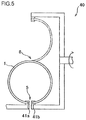
FIG. 5 is an explanatory diagram of a peel test (twist test); and
FIG. 6 is a diagram showing a blow-by gas amount, an oil consumption amount and a wear amount.
BEST MODES FOR CARRYING OUT THE INVENTION
A piston ring of the present invention will be described concretely using the drawings.
FIG. 1A is a perspective view of a piston ring of the present invention which is partially shown in section taken along a direction perpendicular to a radial direction of the piston ring, FIG. 1B is an enlarged sectional view of FIG. 1A, and FIG. 1C is a further enlarged view of FIG. 1B. The piston ring of the present invention is provided with a gap portion, which is not shown in FIGS. 1A to 1C.
As shown in FIGS. 1A to 1C, the piston ring 1 of the present invention is provided at its outer periphery with a sliding surface 10.
As shown in FIGS. 1B and 1C, when a cross section of the piston ring is viewed from a direction perpendicular to a radial direction of the piston ring, the sliding surface 10 includes a first sliding surface m which occupies a predetermined region extending from one end of the piston ring (upper end in FIGS. 1A to 1C) and a second sliding surface n which occupies a region extending from an end of the first sliding surface m to the other end (lower end in FIGS. 1A to 1C). The first sliding surface m is formed of hard film 3, but the hard film 3 does not exist on the second sliding surface n. In an embodiment shown in FIGS. 1A to 1C, a piston ring base material 2 is exposed as it is. The second sliding surface n is characterized in that it exists at a position deviated inward (toward an inner peripheral surface of the piston ring shown in FIG. 1C) from a phantom line S extending from the first sliding surface m toward the other end (lower end in FIGS. 1A to 1C).
According to such a piston ring 1 of the present invention, since the sliding surface 10 includes the first sliding surface m which formed of hard film 3 and the second sliding surface n which is not formed of hard film (piston ring base material 2 is exposed). Therefore, the first sliding surface m can give “wear resistance” to the piston ring 1, and the second sliding surface n can secure “gas seal performance and oil scraping performance”. Further, since the second sliding surface n exists at the position deviated from the phantom line S which is obtained by extending the first sliding surface m toward the lower end, it is possible to prevent the two sliding surfaces (m and n) having different hardness from coming into contact with the cylinder inner peripheral surface at the same time. Hence, it is possible to avoid a case where a scratch or a scuff is generated on the second sliding surface n having hardness lower than that of the first sliding surface m. According to this, the cylinder inner peripheral surface which is a mating member is not damaged or worn, and the piston ring itself is not abnormally worn.
The base material 2 which configures the piston ring 1 of the present invention will be described below.
Material of the base material 2 is not especially limited and any material can be used. For example, steel can be used mainly as the material. As stainless steel, it is possible to use SUS440, SUS410, SUS304 or the like expressed in JIS, or 8Cr steel, 10Cr steel, SWOSC-V, SWRH material or the like.
Next, the first sliding surface m will be described.
The first sliding surface m is characterized in that it occupies the predetermined region of the sliding surface of the piston ring 1 extending from its one end (upper end in FIGS. 1A to 1C), and the first sliding surface m is formed of hard film 3.
Here, the first sliding surface m can be formed by providing a recess 21 in a portion of the piston ring base material 2 which will become the first sliding surface, and by providing the hard film 3 on the recess 21.
The shape of the recess 21 is not especially limited, but it is preferable that a depth h (=thickness of the hard film 3) of the recess 21 gradually becomes shallower (thinner) at the end of the first sliding surface m as shown in FIG. 1C. More specifically, as shown in FIG. 1C, when a cross section of the piston ring which is perpendicular to a radial direction thereof is viewed, it is preferable that the recess 21 is formed in the base material 2 such that the recess 21 includes a first surface X extending from an upper surface to a lower surface (or from the lower surface to the upper surface) of the base material in parallel to a piston ring outer peripheral surface Z and a second surface Y extending from one end X1 of the first surface X toward the piston ring outer peripheral surface Z, and the second surface Y and the piston ring outer peripheral surface Z (surface of the hard film 3 formed on the recess 21) come into contact with each other at an angle of 10° to 30° (see α in FIG. 1C). According to this shape, it is possible to prevent the hard film 3 from being peeled from the piston ring base material 2.
The depth h (=thickness of the hard film 3) of the recess 21 is not especially limited in the invention of the present application, but if performance of the hard film 3 which is provided on the recess 21 and functions as the first sliding surface m and a producing cost are taken into consideration, the depth is preferably about 1 to 70 μm, and more preferably 10 to 60 μm. If the depth is less than 1 μm, there is a problem that the film wears out and durability is deteriorated, and if the depth exceeds 70 μm, producing time is increased and this is not preferable in terms of cost. As described above, the depth h of the recess 21 eventually becomes equal to the thickness of the hard film 3 formed on that portion.
A proportion of the first sliding surface min the entire piston ring sliding surface 10 (i.e., an axial length of the recess 21 provided in the piston ring base material 2) is not especially limited in the invention of the present application. However, to provide the piston ring 1 with wear resistance, it is necessary to sufficiently form the hard film 3 on the sliding surface 10, and a role of the second sliding surface n (details thereof will be described later) which is formed independently from the first sliding surface is to sharpen the edge and to enhance the gas sealing performance and the oil scraping performance. Hence, it is preferable that the proportion of the first sliding surface m (length of the recess 21) is about 75 to 95% of the entire length of the cross section of the piston ring. Therefore, the proportion of the second sliding surface n in the entire sliding surface is 5 to 25% of the entire length. If the proportion of the second sliding surface n in the entire sliding surface is less than 5%, there is a problem that a crack and peeling off can easily be generated, and if the proportion exceeds 25%, a portion having no hard film 3 (first sliding surface m) is increased and there is a problem that the wear resistance is deteriorated.
It is preferable that at least a lower surface 24 of the piston ring base material 2 is subjected to a nitriding treatment, and in addition to this, an upper surface 22 and an inner peripheral surface 23 of the base material 2 may also be subjected to the nitriding treatment. According to this, it is possible to further enhance the wear resistance of the piston ring, a post-treatment becomes unnecessary and the producing step can be simplified.
The nitriding treatment is not especially limited. Examples of the nitriding treatment include a salt bath soft-nitriding treatment, a gas-nitriding treatment, a gas soft-nitriding treatment and an ion-nitriding treatment. It is preferable that a nitride layer having Vickers hardness (HV) of 700 or more is formed by the nitriding treatment as a nitride diffusion layer, a thickness of the nitride diffusion layer is 1 to 40 μm, and the thickness is more preferably 10 to 20 μm.
Next, the hard film 3 forming the first sliding surface will be described.
Material of the hard film 3 is not especially limited, and conventionally used various hard films can appropriately be selected and used only if an effect of the hard film 3 can be obtained, i.e., only if the film can enhance the wear resistance of the piston ring, in other words, only if the film is harder than the piston ring base material 2.
In the present invention, among the various hard films, it is preferable that the film is a Cr—N type or Cr—B—N type film formed by a PVD method (physical vapor deposition method).
Examples of the PVD method for forming the Cr—N type or Cr—B—N type hard film 3 include an ion plating method, a vacuum deposition method and a sputtering method.
It is preferable that the Cr—N type hard film 3 is formed of Cr, CrN and Cr2N, and the Cr—N type hard film 3 includes 0.5 to 15.5% Cr by mass, 45.0 to 98.0% CrN by mass, and a balance of Cr2N.
It is preferable that the Cr—B—N type hard film 3 includes 0.05 to 20% B by mass. The hard film formed by including B in a Cr—N alloy has excellent wear resistance and scuffing resistance, and especially excellent aggressiveness to mated material. If a contained amount of B is less than 0.05% by mass, expected effects of the scuffing resistance and agressiveness to mated material cannot be obtained. If the contained amount of B exceeds 20% by mass, an internal stress of the hard film 3 becomes high, toughness is deteriorated, a crack and delamination are generated in the film, and a function as a piston ring can not be exerted. An especially preferable range of contained amount of B which configures the Cr—B—N type hard film 3 is 1 to 3% by mass, and a contained amount of N which configures the Cr—B—N type hard film 3 is in a range of 4.0 to 34.0% by mass and a balance is Cr.
Next, the second sliding surface n in the piston ring 1 of the present invention will be described.
As described above, the purpose of the second sliding surface n is to give the “gas sealing performance and oil scraping performance” to the piston ring 1. Therefore, it is preferable that an end n1 (other end, lower end in FIGS. 1A to 1C) of the second sliding surface n has a shape which is sharp to some extent.
Unlike the first sliding surface m, the second sliding surface n is not formed of hard film but is formed of the piston ring base material 2 itself as shown in FIGS. 1A to 1C. In other words, the piston ring base material is exposed. If the piston ring base material 2 itself is made as the second sliding surface n in this manner, even if the end n1 is formed into a sharp shape, a fracture such as a crack is not generated in that portion.
The second sliding surface n is characterized in that it exists at the position deviated inward from the phantom line S extending from the first sliding surface toward the other end direction (lower end in FIGS. 1A to 1C), but the deviation amount (f in FIG. 1C) is not especially limited. However, if the deviation amount f is excessively large, there is a fear that blow-by is generated from that portion. Therefore, it is preferable that the deviation amount f is about 1 to 20 μm and more preferably 1 to 10 μm, for example. If the deviation amount f exceeds 20 μm, a possibility that a lodging portion is generated when the piston ring is assembled into a ring groove of the piston and the sliding surface becomes chipped becomes high. If the deviation amount f is set to 10 μm or less, blow-by can be suppressed to a lower value, and it is possible to stably make it difficult to generate the lodging portion. If the deviation amount f is set to 1 μm or more, it is possible to prevent the second sliding surface n from being hitting strongly, and to prevent the second sliding surface n from locally wearing.
From the same viewpoint, it is necessary to take a proportion (5 to 25% of the entire length) of the second sliding surface n in the entire sliding surface (axial direction) into consideration, and it is preferable that the piston ring is designed such that the second sliding surface n becomes about 0.1 to 1.0 mm and more preferably about 0.2 to 0.5 mm, for example.
As described above, in the second sliding surface n, the piston ring base material 2 itself may be exposed, and the sliding surface may be subjected to the nitriding treatment.
Next, the producing method of the piston ring of the present invention will be described.
The producing method is not especially limited, and any producing method may be used only if the piston ring 1 has the above-described features as a final product.
FIGS. 2A to 2E are step diagrams showing one example of the producing method.
As show in FIG. 2A, the piston ring base material 2 provided with the recess 21 for forming the hard film 3 which will become the first sliding surface m is prepared. A depth H of the recess 21 is set deeper than the depth (h in FIG. 1C) of the recess 21 in the piston ring 1 as a final product. In other words, the depth H is deeper than a film thickness of the hard film 3 which will finally be formed on the recess 21. As a forming method of the recess 21, known techniques such as a cutting technique, a grinding technique, a polishing technique and a technique in which a shape is previously formed by wiring material may appropriately be selected and employed.
Next, the hard film 3 is formed on the entire outer peripheral surface of the base material 2 as show in FIG. 2B. The hard film 3 to be formed should have a thickness which is required for the piston ring 1 as the final product. The above-described various PVD methods may be used as the forming method of the hard film 3.
Next, as shown in FIG. 2C, a convex portion (shaded portion in FIG. 2C) formed on the side of a lower surface of the base material 2 is polished and removed along a surface of the hard film 3 formed on the recess 21 of the base material 2. At that time, the piston ring 2 which is softer than the hard film 3 is polished slightly more than the hard film 3 by polishing in parallel to the outer peripheral surface using hard grain (e.g., polishing agent such as Al2O3, SiC and diamond) as polishing agent.
As a result, the second sliding surface is completed at a deviated position as show in FIG. 2D, and the piston ring 1 of the present invention can be formed.
If the nitriding treatment is carried out in this state, a nitride diffusion layer 4 is formed on the piston ring base material 2 as shown in FIG. 2E.
According to the method shown in FIGS. 2A to 2E, after the hard film 3 is formed on the entire outer peripheral surface of the base material 2, the unnecessary portion is removed. According to this, the base material 2 can finally be exposed from a predetermined portion (edge portion on the side of the lower surface). Hence, even when the hard film 3 is formed by the PVD method, it is unnecessary to use a mask and it is possible to relatively easily and inexpensively produce the piston ring of the present invention.
FIGS. 3A and 3B are sectional views showing another example of the piston ring of the present invention.
In the piston ring of the present invention, the sliding surface 10 thereof can be formed into a barrel face shape as shown in FIG. 3A, or the sliding surface 10 can be formed into an eccentric barrel face shape as shown in FIG. 3B. If the sliding surface 10 is formed into the barrel face shape, it is possible to prevent gas from leaking from the outer peripheral surface (sliding surface) while carrying out oil film lubrication.
In this case also, if the second sliding surface is deviated inward from the phantom line S extending from the original barrel face shaped first sliding portion m, the piston ring of the present invention can be obtained.
When the outer peripheral surface of the piston ring has the barrel face shape or the eccentric barrel face shape, the outer peripheral surface Z has a curved surface shape, but it is possible to find a shown in FIG. 1 using a tangent which is portrayed on a boundary point between the first sliding surface m and the second sliding surface n.
The piston ring of the present invention can be used not only for a top ring which functions as a so-called pressure ring, but also for a second ring which is the same pressure ring, and the present invention can also be applied to an oil ring.
FIGS. 1A to 1C and 2A to 2E show an example of the so-called pressure ring. In this case, it is preferable that the hard film 3 is formed on the side of the upper surface of the piston ring and the side of the upper surface is used as the first sliding surface, and the side of the lower surface is used as the second sliding surface n, as shown in FIGS. 1A to 1C and 2A to 2E. This is because that in the pressure ring, it is possible to prevent a crack and peel off by exposing the base material 2 without forming the hard film 3 on the edge portion on the side of the lower surface.
FIGS. 4A and 4B are sectional views when the piston ring of the present invention is applied to the oil ring.
In a two-piece oil ring including a coil expander (not shown) and an oil ring body 1, as shown in FIG. 4A, the hard film 3 can be formed on upper and lower two sliding surfaces and on the side of the upper surface and they can be used as the first sliding surfaces m, and the side of the lower surface can be used as the second sliding surfaces n. In this case, an oil scraping direction is a downward direction of the oil ring body 1.
As shown in FIG. 4B, in the case of the upper sliding surface, the hard film 3 may be formed on the side of the upper surface and this may be made as the first sliding surface m, and the side of the lower surface may be made as the second sliding surface n, and in the case of the lower sliding surface, the hard film 3 may be formed on the side of the lower surface and this may be made as the first sliding surface m, and the side of the upper surface may be made as the second sliding surface n. In this case, an oil scraping direction is a central portion of the oil ring body 1.
EXAMPLES
The piston ring of the present invention will be described in more concretely using Examples.
Examples 1 to 12
The piston ring (oil ring) shown in FIG. 1 was produced using the method explained using FIGS. 2A to 2E.
Here, SUS440B expressed in JIS was used as the base material (2).
The hard films (3) were Cr—B—N (Examples 1 to 6) and Cr—N (Examples 7 to 12) formed by the ion plating method.
Sizes of the produced piston ring were as follows: a diameter was 115 mm, a width (h1) in the axial direction was 3.0 mm, and a width (a1) in the radial direction was 3.95 mm. A length (n) of the base material exposed from a lower portion (edge portion) of an outer peripheral sliding surface of the piston ring was 0.2 to 0.5 mm.
In the Examples 1 to 12, a value of an angle (α) formed between the piston ring outer peripheral surface (Z) and the second surface (Y) which configures the recess (21) formed in the base material (2) is as shown in Table 1. The piston ring was cut so that a cross section thereof in its axial direction could be observed, the cross section was polished and mirror-polished, the cross section was magnified a hundred times and the angle (α) formed between the second surface (Y) and the piston ring outer peripheral surface (Z) was checked. In these Examples, as shown in the following Table 1, some portions of the base materials where the hard films (3) were formed were subjected to the nitriding treatment, and other portions of the base materials where the hard films (3) were formed were not subjected to the nitriding treatment.
Concerning the nitriding treatment, nitride diffusion layers having thicknesses of 10 to 20 μm were formed using the gas nitriding method.
Comparative Examples 1 to 4
Piston rings of comparative examples were produced in the same manner as those of the Examples. In the piston rings of the comparative examples, a value of the angle (α) formed between the piston ring outer peripheral surface (Z) and the second surface (Y) which configured the recess (21) formed in the base material (2) was set to 30°, and the deviation amount f of the second sliding surface was set to 0 (zero). Details thereof are as shown in Table 1.
Conventional Examples 1 to 2
Conventional examples in which hard films (3) were formed on the entire outer peripheral surfaces of the base materials (2) were produced in the same manner as those of the Examples. Details thereof are as shown in Table 1.
<Peel Test>
A twist test was carried out using a twist peel test machine 40 shown in FIG. 5.
In the twist test, opposed mating ends of a gap 5 of the piston ring 1 are held by holding tools 41 a and 41 b, the holding tool 41 a is fixed, the holding tool 41 b is rotated around an opposite side 6 of the gap in a radial direction of the piston ring 1 as shown with dashed lines, and the piston ring 1 is twisted at a predetermined twisting angle. The twisting angle was 90°. After the piston ring 1 was twisted, the opposite side 6 which was opposite from the gap of the piston ring 1 was cut, and it was visually observed whether a film layer in the cut surface (fracture) was peeled off from a ring base material. As a result of the observation, a case where a crack or peel was not found at all was shown with O, and a case where a crack or peel was found even slightly was shown with x. The peel test was carried out for the Examples 1, 4, 5, 7, 10, 11, the comparative examples 1 to 4 and the conventional example 1.
A result thereof is shown in the following Table 1.
TABLE 1
Surface
treatment of Result of
α n(mm) f(μm) Film base material peel test
Example 1 10 0.3 6 Cr—B—N None
Example 2 10 0.4 3 Cr—B—N Nitride layer
Example 3 15 0.4 4 Cr—B—N Nitride layer
Example 4 20 0.3 5 Cr—B—N None
Example 5 30 0.5 10 Cr—B—N None
Example 6 30 0.5 2 Cr—B—N Nitride layer
Example 7 10 0.2 5 Cr—N None
Example 8 10 0.3 4 Cr—N Nitride layer
Example 9 15 0.3 3 Cr—N Nitride layer
Example 10 20 0.3 5 Cr—N None
Example 11 30 0.4 7 Cr—N None
Example 12 30 0.3 3 Cr—N Nitride layer
Comparative 30 0.5 0 Cr—B—N None
Example 1
Comparative 30 0.8 0 Cr—B—N None
Example 2
Comparative 30 0.5 0 Cr—B—N Nitride layer
Example 3
Comparative 30 0.8 0 Cr—B—N Nitride layer
Example 4
Conventional Cr—B—N None
Example 1
Conventional Cr—B—N Nitride layer
Example 2

<Real Machine Test>
An oil consumption amount and a blow-by gas amount were measured using an inline six-cylinder diesel engine having a piston displacement of 8,000 cc and a bore diameter of ϕ115 mm. A wear amount of a lower surface of a first pressure ring was measured by profiles before and after a real machine was operated.
A combination of piston rings at that time is as follows: a first pressure ring includes 0.9% C (by mass), 0.4% Si, 0.3% Mn, 17.5% Cr, 1.1% Mo, 0.1% V, 0.01% P, and 0.01% S (corresponding to SUS440B material expressed in JIS), a width (h1) of the ring in its axial direction is 3.0 mm, a width (a1) of the ring in its radial direction is 3.95 mm, specifications of the Examples 3 and 4 and the conventional example 1 are used, a second pressure ring includes material corresponding to 10Cr steel material, a width (h1) of the ring in its axial direction is 2.5 mm, and a width (a1) of the ring in its radial direction is 4.3 mm. The oil ring corresponds to SUS410J1 material expressed in JIS, a width (h1) of the ring in its axial direction is 4.0 mm, a width (a1) of a single oil ring in its radial direction is 2.35 mm, and a width (a1) is 4.35 mm when the oil ring is combined with a coil expander.
In the real machine test, specifications of the second pressure ring and the oil ring were constant, and only the first pressure ring was changed. An outer peripheral sliding surface of the first pressure ring was formed into a barrel face shape, and an outer peripheral sliding surface of the second pressure ring was formed into a tapered shape.
The concrete test method was as follows: the engine revolution number was 2,200 rpm under a condition of WOT (Wide Open Throttle), numeric values of a blow-by gas amount using a pressure ring of the conventional example 1 and an oil consumption amount were defined as 1, and a result of a test was obtained using compression rings of the conventional example 2 and the Examples 2, 3, 5 and 6. Concerning the wear amount, a numeric value of a wear amount of a ring lower surface using a pressure ring of the conventional example 1 was defined as 1, and results of tests using the compression rings of the Examples 3, 5 and 6 were obtained as indices. Results thereof are shown in FIG. 6.
As can be found from Table 1 and FIG. 6, according to the piston ring of the present invention, it is possible to enhance peel resistance, wear resistance, gas sealing performance and oil scraping performance as compared with those of the conventional technique.
DESCRIPTION OF REFERENCE NUMERALS
  • 1 . . . piston ring
  • 2 . . . base material
  • 3 . . . hard film
  • 4 . . . nitride diffusion layer
  • 5 . . . gap
  • 10 . . . sliding surface
  • 21 . . . recess
  • m . . . first sliding surface
  • n . . . second sliding surface
  • S . . . phantom line

Claims (17)

The invention claimed is:
1. A method for producing a piston ring for a cylinder that moves in a sliding direction, comprising:
providing a wire rod being formed by a piston ring base material and having an upper surface, a lower surface, a pre-formed first recess and a cylindrical surface, a first recess extending from the upper surface to the cylindrical surface, the cylindrical surface extending from the first recess to the lower surface, the first recess having a bottom surface parallel to the cylindrical surface and an inclined surface extending from the bottom surface to the cylindrical surface;
forming a hard film on the bottom surface and the inclined surface of the first recess and on the cylindrical surface at a predetermined thickness, the hard film having a higher hardness than the piston ring base material, an outer surface of the hard film on the bottom surface of the first recess establishing a sliding surface;
forming a second recess by performing a polishing process on the sliding surface based on at least three steps including:
removing the hard film formed on the cylindrical surface;
removing the hard film formed on a part of the inclined surface of the first recess and a second part of the piston ring base material disposed adjacent to the cylindrical surface, to a point substantially flush with the sliding surface, and
removing a third part of the piston ring base material from a section of the piston ring base material exposed by removal of the second part of the piston ring base material,
wherein the second recess is directly connecting the first recess and forming a connecting vertex with the inclined surface of the first recess.
2. The method according to claim 1, further comprising:
forming a nitride diffusion layer on the piston ring base material after forming the second recess.
3. The method according to claim 2, wherein the nitride diffusion layer is directly formed on the upper surface and the lower surface of the piston ring base material and on the second recess.
4. The method according to claim 1, wherein the inclined surface forms an angle 10°-30° with the sliding surface.
5. The method according to claim 1, wherein the first recess has a higher depth from the sliding surface than the second recess.
6. The method according to claim 1, wherein the first recess has a depth of 10 μm to 60 μm.
7. The method according to claim 1, wherein the second recess has a depth of 1 μm to 20 μm.
8. The method according to claim 1, wherein a length of the second recess in the sliding direction is about 5%-25% of a distance between the upper surface and the lower surface of the piston ring base material in the sliding direction.
9. The method according to claim 1, wherein the hard film is formed by a PVD method.
10. The method according to claim 1, wherein the hard film comprises a Cr—N type film or a Cr—B—N type film.
11. The method according to claim 1, wherein the second recess has a curved surface extending from the connecting vertex.
12. The method according to claim 11, wherein the second recess further has a flat surface extending from the lower surface of the piston ring base material and the curved surface.
13. The method according to claim 1, wherein the predetermined thickness for the hard film formed in the first recess and on the cylindrical surface is substantially the same as a depth of the first recess after removing the hard film on the part of the inclined surface of the first recess and the second part of the piston ring base material disposed adjacent to the cylindrical surface at the second step.
14. The method according to claim 1, wherein the sliding surface is polished such that the sliding surface is parallel with the sliding direction.
15. The method according to claim 1, wherein the sliding surface is polished such that the sliding surface is curved relative to the sliding direction.
16. The method according to claim 15, wherein the sliding surface has a barrel face shape.
17. The method according to claim 15, wherein the sliding surface has an eccentric barrel face shape.
US16/685,352 2009-11-30 2019-11-15 Method for producing piston ring with recess Active 2030-02-12 US11047479B2 (en)

Priority Applications (1)

Application Number Priority Date Filing Date Title
US16/685,352 US11047479B2 (en) 2009-11-30 2019-11-15 Method for producing piston ring with recess

Applications Claiming Priority (4)

Application Number Priority Date Filing Date Title
PCT/JP2009/070117 WO2011064888A1 (en) 2009-11-30 2009-11-30 Piston ring
US201213503381A 2012-04-23 2012-04-23
US15/672,942 US10514097B2 (en) 2009-11-30 2017-08-09 Method for producing piston ring with recess
US16/685,352 US11047479B2 (en) 2009-11-30 2019-11-15 Method for producing piston ring with recess

Related Parent Applications (1)

Application Number Title Priority Date Filing Date
US15/672,942 Continuation US10514097B2 (en) 2009-11-30 2017-08-09 Method for producing piston ring with recess

Publications (2)

Publication Number Publication Date
US20200080638A1 US20200080638A1 (en) 2020-03-12
US11047479B2 true US11047479B2 (en) 2021-06-29

Family

ID=44066007

Family Applications (3)

Application Number Title Priority Date Filing Date
US13/503,381 Abandoned US20120205876A1 (en) 2009-11-30 2009-11-30 Piston ring
US15/672,942 Active 2030-04-11 US10514097B2 (en) 2009-11-30 2017-08-09 Method for producing piston ring with recess
US16/685,352 Active 2030-02-12 US11047479B2 (en) 2009-11-30 2019-11-15 Method for producing piston ring with recess

Family Applications Before (2)

Application Number Title Priority Date Filing Date
US13/503,381 Abandoned US20120205876A1 (en) 2009-11-30 2009-11-30 Piston ring
US15/672,942 Active 2030-04-11 US10514097B2 (en) 2009-11-30 2017-08-09 Method for producing piston ring with recess

Country Status (4)

Country Link
US (3) US20120205876A1 (en)
EP (1) EP2508740B1 (en)
CN (1) CN102639851B (en)
WO (1) WO2011064888A1 (en)

Families Citing this family (29)

* Cited by examiner, † Cited by third party
Publication number Priority date Publication date Assignee Title
DE102010047836B4 (en) 2010-10-07 2014-09-04 Federal-Mogul Burscheid Gmbh Method for producing a piston ring
DE102010047961A1 (en) * 2010-10-08 2012-04-12 Federal-Mogul Burscheid Gmbh Method for producing a piston ring
DE102011120145A1 (en) 2010-12-24 2012-06-28 Mahle International Gmbh Piston ring for a piston of an internal combustion engine and method for its production
JP5564082B2 (en) * 2012-08-09 2014-07-30 株式会社リケン Tapered face type pressure ring wire and tapered face type pressure ring
CN104685267B (en) * 2012-10-02 2017-02-22 株式会社理研 Piston ring
US20180274675A1 (en) * 2012-11-09 2018-09-27 Federal-Mogul Burscheid Gmbh Piston ring with varying apex lines
BR112015015720A2 (en) * 2012-12-31 2017-07-11 Mahle Int Gmbh double coated piston ring
DE102013200261A1 (en) * 2013-01-10 2014-07-10 Federal-Mogul Burscheid Gmbh Piston ring for internal combustion engines with increased fatigue strength and method for its production
DE102013205912A1 (en) * 2013-04-04 2014-10-09 Federal-Mogul Burscheid Gmbh Piston ring with wear indicator
BR102013018952B1 (en) * 2013-07-24 2021-10-26 Mahle Metal Leve S/A SLIDING SET
JP5860571B1 (en) * 2014-02-19 2016-02-16 株式会社リケン piston ring
KR102426972B1 (en) 2014-06-27 2022-07-29 가부시끼가이샤 리켄 Piston ring
GB2533274A (en) * 2014-12-08 2016-06-22 Skf Ab Method of manufacturing a seal
JP6496578B2 (en) * 2015-03-12 2019-04-03 株式会社リケン piston ring
DE102015111672A1 (en) * 2015-07-17 2017-01-19 Federal-Mogul Burscheid Gmbh piston ring
DE102015009587B4 (en) * 2015-07-24 2018-11-22 Federal-Mogul Burscheid Gmbh Compression piston ring
BR102015020400A2 (en) * 2015-08-24 2017-03-01 Mahle Int Gmbh piston ring
SE1500438A1 (en) * 2015-11-02 2017-05-03 Flutron Ab High pressure seal of metallic like material
DE102016104454B4 (en) * 2016-03-11 2021-05-27 Federal-Mogul Burscheid Gmbh Piston ring
DE102016113678B4 (en) * 2016-07-25 2018-05-09 Federal-Mogul Burscheid Gmbh One-piece oil scraper ring
DE102017100173A1 (en) * 2017-01-05 2018-07-05 Federal-Mogul Burscheid Gmbh Piston ring with stepped tread
DE102017104221A1 (en) * 2017-03-01 2018-09-06 Federal-Mogul Burscheid Gmbh piston ring
JP6603284B2 (en) * 2017-10-05 2019-11-06 株式会社リケン side rail
CN108799493B (en) * 2018-06-08 2020-01-07 安徽共青机电装备制造有限公司 Piston ring for oil-free lubrication compressor
US11162585B2 (en) * 2019-01-31 2021-11-02 Mahle International Gmbh Piston having two piston rings
DK180594B1 (en) * 2020-06-15 2021-09-30 Man Energy Solutions Filial Af Man Energy Solutions Se Tyskland A piston ring for use in a ring pack in a piston of a large two-stroke turbo-charged uniflow-scavenged internal combustion engine with crossheads
CN112377614B (en) * 2020-11-11 2023-02-24 马勒汽车技术(中国)有限公司 Piston ring for engine and machining method of piston ring
JP7284308B1 (en) * 2022-02-28 2023-05-30 Tpr株式会社 piston ring
WO2024053065A1 (en) * 2022-09-08 2024-03-14 Tpr株式会社 Compression ring

Citations (15)

* Cited by examiner, † Cited by third party
Publication number Priority date Publication date Assignee Title
US2511874A (en) 1950-06-20 Piston ring
GB1133753A (en) 1966-05-20 1968-11-20 Ramsay Corp Improvements in or relating to the manufacture of compression rings
US3947046A (en) 1973-05-30 1976-03-30 Riken Piston Ring Kogyo Kabushiki Kaisha Oil seal ring for internal combustion engine
JPS5569742A (en) 1978-11-20 1980-05-26 Toyota Motor Corp Piston ring for internal combustion engine
JPS61146657A (en) 1984-12-19 1986-07-04 Fujitsu Ten Ltd Wiper driving device
JPH0730347U (en) 1993-11-01 1995-06-06 帝国ピストンリング株式会社 engine
US6206379B1 (en) * 1997-03-14 2001-03-27 Nippon Piston Ring Co., Ltd. Second pressure ring for Al cylinders and its producing method
US20020190476A1 (en) * 2000-01-20 2002-12-19 Karlfried Preyer Oil-scrapper piston ring and a method for producing an oil-scraper piston ring
JP2005114096A (en) 2003-10-09 2005-04-28 Riken Corp Piston ring and its manufacturing method
JP2005273583A (en) 2004-03-25 2005-10-06 Toyota Motor Corp Piston ring
US20070128807A1 (en) 2003-12-19 2007-06-07 Manfred Fischer Piston ring and method for the production thereof
US7354045B2 (en) 2002-10-29 2008-04-08 Toyota Jidosha Kabushiki Kaisha Oil ring
CN101205849A (en) 2006-12-18 2008-06-25 瓦特西拉瑞士股份有限公司 Piston with oil collector ring
US20090174150A1 (en) 2008-01-08 2009-07-09 Thomas Smith Lateral side protection of a piston ring with a thermally sprayed coating
US20100044967A1 (en) 2007-02-17 2010-02-25 Johannes Esser Piston ring

Family Cites Families (3)

* Cited by examiner, † Cited by third party
Publication number Priority date Publication date Assignee Title
DE2523953C3 (en) 1975-05-30 1980-05-14 Dr.Ing.H.C. F. Porsche Ag, 7000 Stuttgart Synchronizing device, in particular for speed change transmissions in motor vehicles
JPS61146657U (en) * 1985-03-04 1986-09-10
US5206379A (en) 1990-11-07 1993-04-27 Fuji Photo Film Co., Ltd. α-acylmethoxycarbonylbenzotriazoles

Patent Citations (18)

* Cited by examiner, † Cited by third party
Publication number Priority date Publication date Assignee Title
US2511874A (en) 1950-06-20 Piston ring
GB1133753A (en) 1966-05-20 1968-11-20 Ramsay Corp Improvements in or relating to the manufacture of compression rings
US3947046A (en) 1973-05-30 1976-03-30 Riken Piston Ring Kogyo Kabushiki Kaisha Oil seal ring for internal combustion engine
JPS5569742A (en) 1978-11-20 1980-05-26 Toyota Motor Corp Piston ring for internal combustion engine
US4323257A (en) 1978-11-20 1982-04-06 Toyota Jidosha Kogyo Kabushiki Kaisha Piston ring with a Cr-C-Fe inlaid ring in its outer surface, and a method of making it
JPS61146657A (en) 1984-12-19 1986-07-04 Fujitsu Ten Ltd Wiper driving device
JPH0730347U (en) 1993-11-01 1995-06-06 帝国ピストンリング株式会社 engine
US6206379B1 (en) * 1997-03-14 2001-03-27 Nippon Piston Ring Co., Ltd. Second pressure ring for Al cylinders and its producing method
US20020190476A1 (en) * 2000-01-20 2002-12-19 Karlfried Preyer Oil-scrapper piston ring and a method for producing an oil-scraper piston ring
US7354045B2 (en) 2002-10-29 2008-04-08 Toyota Jidosha Kabushiki Kaisha Oil ring
JP2005114096A (en) 2003-10-09 2005-04-28 Riken Corp Piston ring and its manufacturing method
US20070128807A1 (en) 2003-12-19 2007-06-07 Manfred Fischer Piston ring and method for the production thereof
JP2007520666A (en) 2003-12-19 2007-07-26 フェデラル−モーグル ブルシャイト ゲゼルシャフト ミット ベシュレンクテル ハフツング Piston ring and manufacturing method thereof
US7871078B2 (en) 2003-12-19 2011-01-18 Federal-Mogul Burscheid Gmbh Piston ring and method for the production thereof
JP2005273583A (en) 2004-03-25 2005-10-06 Toyota Motor Corp Piston ring
CN101205849A (en) 2006-12-18 2008-06-25 瓦特西拉瑞士股份有限公司 Piston with oil collector ring
US20100044967A1 (en) 2007-02-17 2010-02-25 Johannes Esser Piston ring
US20090174150A1 (en) 2008-01-08 2009-07-09 Thomas Smith Lateral side protection of a piston ring with a thermally sprayed coating

Non-Patent Citations (2)

* Cited by examiner, † Cited by third party
Title
Extended European search report, dated Feb. 19, 2015, in corresponding European Patent Application No. 09851678.4 (Cited in the IDS filed in parent U.S. Appl. No. 13/503,381).
International Search Report, PCT/JP2009/070117, dated Dec. 28, 2009 (Cited in the IDS filed in parent U.S. Appl. No. 13/503,381).

Also Published As

Publication number Publication date
US20120205876A1 (en) 2012-08-16
US20170335965A1 (en) 2017-11-23
CN102639851A (en) 2012-08-15
EP2508740B1 (en) 2017-05-31
EP2508740A4 (en) 2015-03-25
CN102639851B (en) 2015-08-12
WO2011064888A1 (en) 2011-06-03
US20200080638A1 (en) 2020-03-12
JP5557850B2 (en) 2014-07-23
US10514097B2 (en) 2019-12-24
EP2508740A1 (en) 2012-10-10
JPWO2011064888A1 (en) 2013-04-11

Similar Documents

Publication Publication Date Title
US11047479B2 (en) Method for producing piston ring with recess
US7572344B2 (en) Method for the production of wear-resistant sides for a keystone ring for internal combustion engine
US6279913B1 (en) Sliding member and manufacturing method thereof
US9506138B2 (en) Piston ring
EP2578908B1 (en) Oil ring for internal combustion engine
US20090026712A1 (en) Sliding Member
RU2577642C2 (en) Method of producing piston rings
WO2016038916A1 (en) Combined oil ring
JP3228116B2 (en) Combination oil ring
US9067286B2 (en) Piston ring for a piston of an internal combustion engine, and a method for producing same
US20120248711A1 (en) Piston ring
US20200256277A1 (en) Cast iron cylinder liner, and internal combustion engine
JP5276361B2 (en) piston ring
CN104169555A (en) Combination of cylinder and piston ring
JP5833276B1 (en) Combination oil ring
JP7219776B2 (en) piston ring
RU2727466C2 (en) Piston ring with protective layer having coating
JP5860571B1 (en) piston ring
JP5557850B6 (en) piston ring
WO2019229070A1 (en) Piston ring and method for manufacturing a piston ring
EP2746624B1 (en) Piston ring
JP2018141197A (en) Sliding member and method for manufacturing the same
JP2013061072A (en) Piston ring
JP2003194223A (en) Combinational oil ring

Legal Events

Date Code Title Description
FEPP Fee payment procedure

Free format text: ENTITY STATUS SET TO UNDISCOUNTED (ORIGINAL EVENT CODE: BIG.); ENTITY STATUS OF PATENT OWNER: LARGE ENTITY

STPP Information on status: patent application and granting procedure in general

Free format text: NON FINAL ACTION MAILED

STPP Information on status: patent application and granting procedure in general

Free format text: RESPONSE TO NON-FINAL OFFICE ACTION ENTERED AND FORWARDED TO EXAMINER

STPP Information on status: patent application and granting procedure in general

Free format text: NOTICE OF ALLOWANCE MAILED -- APPLICATION RECEIVED IN OFFICE OF PUBLICATIONS

STPP Information on status: patent application and granting procedure in general

Free format text: PUBLICATIONS -- ISSUE FEE PAYMENT RECEIVED

STPP Information on status: patent application and granting procedure in general

Free format text: PUBLICATIONS -- ISSUE FEE PAYMENT VERIFIED

STCF Information on status: patent grant

Free format text: PATENTED CASE