US11046357B2 - Method for the simplified assembly of a rack-and-pinion steering box of a rack-and-pinion steering system - Google Patents
Method for the simplified assembly of a rack-and-pinion steering box of a rack-and-pinion steering system Download PDFInfo
- Publication number
- US11046357B2 US11046357B2 US16/344,597 US201716344597A US11046357B2 US 11046357 B2 US11046357 B2 US 11046357B2 US 201716344597 A US201716344597 A US 201716344597A US 11046357 B2 US11046357 B2 US 11046357B2
- Authority
- US
- United States
- Prior art keywords
- steering
- pinion
- rack
- shaft
- pinion shaft
- Prior art date
- Legal status (The legal status is an assumption and is not a legal conclusion. Google has not performed a legal analysis and makes no representation as to the accuracy of the status listed.)
- Active, expires
Links
Images


Classifications
-
- B—PERFORMING OPERATIONS; TRANSPORTING
- B62—LAND VEHICLES FOR TRAVELLING OTHERWISE THAN ON RAILS
- B62D—MOTOR VEHICLES; TRAILERS
- B62D5/00—Power-assisted or power-driven steering
- B62D5/04—Power-assisted or power-driven steering electrical, e.g. using an electric servo-motor connected to, or forming part of, the steering gear
- B62D5/0442—Conversion of rotational into longitudinal movement
- B62D5/0454—Worm gears
-
- B—PERFORMING OPERATIONS; TRANSPORTING
- B62—LAND VEHICLES FOR TRAVELLING OTHERWISE THAN ON RAILS
- B62D—MOTOR VEHICLES; TRAILERS
- B62D3/00—Steering gears
- B62D3/02—Steering gears mechanical
- B62D3/12—Steering gears mechanical of rack-and-pinion type
-
- B—PERFORMING OPERATIONS; TRANSPORTING
- B62—LAND VEHICLES FOR TRAVELLING OTHERWISE THAN ON RAILS
- B62D—MOTOR VEHICLES; TRAILERS
- B62D5/00—Power-assisted or power-driven steering
- B62D5/04—Power-assisted or power-driven steering electrical, e.g. using an electric servo-motor connected to, or forming part of, the steering gear
- B62D5/0403—Power-assisted or power-driven steering electrical, e.g. using an electric servo-motor connected to, or forming part of, the steering gear characterised by constructional features, e.g. common housing for motor and gear box
-
- B—PERFORMING OPERATIONS; TRANSPORTING
- B62—LAND VEHICLES FOR TRAVELLING OTHERWISE THAN ON RAILS
- B62D—MOTOR VEHICLES; TRAILERS
- B62D5/00—Power-assisted or power-driven steering
- B62D5/04—Power-assisted or power-driven steering electrical, e.g. using an electric servo-motor connected to, or forming part of, the steering gear
- B62D5/0421—Electric motor acting on or near steering gear
Definitions
- the present disclosure generally relates to steering systems, including methods for assembling a rack-and-pinion steering gear of a rack-and-pinion steering system.
- Generic rack-and-pinion steering systems comprise a rack, which is guided in linearly movable fashion in a steering gear housing, and a rotatably mounted steering pinion, which is in engagement with the rack.
- the steering torque applied to a steering wheel by a driver is transmitted via a steering shaft to an input shaft of the steering gear.
- the input shaft of the steering gear is connected to a steering pinion, which meshes with the rack.
- a rotation of the input shaft and of the steering pinion is converted by means of the toothed engagement of the rack into a linear movement of the rack.
- Articulatedly connected to the rack are track rods, by means of which the steered wheels are adjusted by a steer angle. The rotation of the steering wheel is thus converted into a steering movement of the steered wheels.
- a servo motor which acts, for example via a mechanical reduction gear with worm and worm wheel, on the steering pinion and thus assists the driver in a steering maneuver.
- the servo motor is arranged between the input shaft and the steering pinion. This arrangement can however prove to be disadvantageous, because the steering pinion and rack can be placed in operative connection only with difficulty.
- FIG. 1 is a schematic side view of an example rack-and-pinion steering system.
- FIG. 2 is a perspective view of the steering gear from FIG. 1 .
- FIG. 3 is a detail view illustrating engagement of an example rack with an example steering pinion.
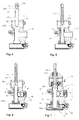
- FIG. 4 is a longitudinal sectional view of an example rack-and-pinion steering system in a first step of an example method of assembly.
- FIG. 5 is a longitudinal sectional view of an example rack-and-pinion steering system in a second step of an example method of assembly.
- FIG. 6 is a longitudinal sectional view of an example rack-and-pinion steering system in a third step of an example method of assembly.
- FIG. 7 is a longitudinal sectional view of an example rack-and-pinion steering system in a fourth step of an example method of assembly.
- FIG. 8 is a perspective view of an example rack-and-dual-pinion steering system.
- a method for assembling a rack-and-pinion steering gear of a rack-and-pinion steering system comprising a pinion shaft connected to a steering shaft, which pinion shaft comprises a steering pinion which is in engagement with a rack for pivoting steerable wheels, and wherein the rack-and-pinion steering system comprises an electric motor which drives the pinion shaft via a reduction gear, characterized in that the steering shaft, the pinion shaft with the steering pinion and the reduction gear form a collective arrangement which is accommodated in a steering gear housing, wherein the pinion shaft comprises, between the steering pinion and an end remote from the steering shaft, a narrowed portion whose diameter is smaller than that of the steering pinion, wherein the following method steps are provided:
- the steering gear is thus particularly easy to assemble because the pinion and the rack can be introduced in succession into the housing.
- This method furthermore has the advantage that the steering gear housing can be formed as a single piece.
- the diameter of the narrowed portion is smaller than that of the steering pinion and of the rest of the pinion shaft; it can thus be ensured that the steering rack can be pushed past the pinion shaft.
- the narrowed portion directly adjoins the steering pinion on the pinion shaft.
- the pinion shaft can thus be introduced into the housing already to a very great extent in step a), and only has to be moved slightly in step c) in order to produce the engagement.
- the pinion shaft is preferably mounted rotatably in the steering gear housing in a bearing, wherein the narrowed portion is arranged between the steering pinion and the bearing.
- step c) provision is made whereby, after step c), the reduction gear is introduced, at that end of the pinion shaft which is remote from the steering shaft, into the steering gear housing.
- the assembly of the reduction gear is thus likewise particularly straightforward.
- a rack-and-pinion steering system for a motor vehicle, comprising a pinion shaft connected to a steering shaft, which pinion shaft comprises a steering pinion which is in engagement with a rack, which rack is mounted in a housing so as to be displaceable along a longitudinal axis, in order to pivot steerable wheels, wherein the steering shaft, the pinion shaft with the steering pinion and the reduction gear form a collective arrangement which is accommodated in a steering gear housing, and having an electric motor which drives the pinion shaft via a reduction gear, wherein the pinion shaft comprises, between the steering pinion and an end remote from the steering shaft, a narrowed portion whose diameter is smaller than that of the steering pinion, such that, during the assembly of the rack-and-pinion steering gear, the rack can be pushed into the steering gear housing past the narrowed portion of the pinion shaft into an end position.
- the pinion shaft is, between the steering pinion and the reduction gear, mounted rotatably in the steering gear housing in a bearing. It is furthermore preferable if the pinion shaft comprises, between the steering pinion and the bearing, the narrowed portion, whose diameter is smaller than that of the steering pinion and of a bearing seat of the bearing; it is thus ensured that the rack can be pushed past the pinion shaft into the housing.
- the narrowed portion preferably directly adjoins the steering pinion on the pinion shaft.
- the diameter of the narrowed portion is smaller than the diameter of the steering pinion and of the rest of the pinion shaft.
- the electric motor and the reduction gear are arranged on the underside of the steering gear at the end remote from the steering shaft.
- the drive requires particularly little structural space.
- the pinion shaft is, at its end close to the steering shaft, connected to a torsion bar which connects the pinion shaft to an input shaft, wherein the torsion bar is part of a torque sensor which determines the steering moment that has to be applied to a steering wheel in order to activate the electric motor, wherein the reduction gear and the electric motor are arranged on the opposite side of the rack in relation to the torque sensor.
- the reduction gear and the electric motor are thus provided on that side of the pinion shaft which is remote from the steering shaft, and are thus situated, below the rack, relatively close to the roadway, which is particularly space-saving.
- the reduction gear is a worm gear, wherein a worm wheel of the worm gear concentrically surrounds, and is connected rotationally conjointly to, the pinion shaft.
- the steering gear housing is preferably formed as a single piece with the drive gear housing in which the reduction gear is accommodated.
- FIG. 1 schematically shows a rack-and-pinion steering system 1 of a motor vehicle.
- a steering shaft 2 serves for transmitting the steering movements performed by a driver of the motor vehicle at a steering wheel 3 to a rack-and-pinion steering gear 4 .
- the rack-and-pinion steering gear 4 converts a rotational movement of the steering shaft 2 into a movement of a rack 5 , whereby the wheel 7 , which is articulated on a track rod 6 , of the vehicle performs a steering movement.
- the rotational movement of the steering shaft 2 is converted by means of a steering pinion 8 , which meshes with the rack 5 in a toothing region 9 , into a translational movement of the rack 5 .
- the rack 5 is mounted in axially movable fashion in a steering gear housing 10 .
- a reduction gear 11 On that side of the rack 5 which is remote from the steering shaft, there are arranged a reduction gear 11 and an electric servo motor 12 .
- the servo motor 12 acts via the reduction gear 11 on the steering pinion 8 for the purposes of steering assistance.
- FIG. 2 illustrates, in a second view, the position of the reduction gear 11 and of the servo motor 12 below the rack 5 , that is to say so as to be situated relatively close to the roadway 70 .
- FIG. 3 shows the engagement of the steering pinion 8 into the toothing region 9 of the rack 5 .
- the steering pinion 8 is arranged on a pinion shaft 13 , which comprises an end 130 close to the steering shaft and an end 1300 remote from the steering shaft.
- the end 130 close to the steering shaft is connected to a torsion bar 115 , which connects the pinion shaft 13 to an input shaft 113 , which is in turn connected rotationally conjointly to the steering wheel 3 via the steering shaft 2 .
- the torsion bar 115 gives rise to a relative rotation between the input shaft 113 and the pinion shaft 13 .
- the torsion bar 115 is part of a torque sensor 114 , which determines the steering moment that has to be applied to the steering wheel 3 in order to activate the electric motor 12 .
- the pinion shaft 13 is, between the steering pinion 8 and the end 1300 remote from the steering shaft, mounted rotatably in the steering gear housing 10 in a bearing 14 .
- a worm wheel 15 of the reduction gear 11 At that end 1300 of the pinion shaft 13 which is remote from the steering shaft, there is provided a worm wheel 15 of the reduction gear 11 , which worm wheel concentrically surrounds, and is connected rotationally conjointly to, the pinion shaft 13 .
- the electric servo motor (not illustrated here) drives a worm shaft 16 , which meshes with the worm wheel 15 arranged on the pinion shaft 13 .
- the servo motor can likewise be attached to the underside of the steering gear 4 , which is particularly space-saving.
- the underside is to be understood here to mean that side of the steering gear 4 which points in the direction of the roadway 70 .
- the pinion shaft 13 comprises a narrowed portion 17 , whose diameter is smaller than that of the steering pinion 8 and of a bearing seat 140 of the bearing 14 .
- the diameter of the narrowed portion 17 is furthermore smaller than the rest of the pinion shaft 13 .
- the narrowed portion 17 preferably directly adjoins the steering pinion 8 .
- FIGS. 4 to 7 show the assembly of the rack-and-pinion steering gear 4 in multiple steps.
- a first step the input shaft 113 with torsion bar 115 and steering pinion 13 is pushed into a housing opening, provided for the same, of the steering gear housing 10 , specifically to such an extent that the region of the narrowed portion 17 of the pinion shaft 13 is situated at the level of the rack 5 to be inserted, and that end 1300 of the pinion shaft 13 which is remote from the steering shaft is surrounded by the bearing 14 .
- the rack 5 is pushed into the housing opening correspondingly provided for the same. The rack 5 can be pushed past the narrowed portion 17 of the pinion shaft 13 into a setpoint position.
- the pinion shaft 13 is subsequently pushed downward, further into the steering gear housing 10 , as far as an end position, such that the toothing region 9 of the rack 5 enters into engagement with the toothing of the steering pinion 8 .
- the bearing 14 is thus situated on the bearing seat 140 of the pinion shaft 13 and the worm wheel 15 can be fastened to that end 1300 of the pinion shaft 13 which is remote from the steering shaft.
- the rack-and-pinion mechanism can thus be assembled particularly easily in the steering gear housing 10 . After the steering gear has been assembled, the worm 16 is introduced into an opening, provided for the same, of the drive gear housing.
- the bearing 14 is arranged on the bearing seat 140 of the pinion shaft 13 , and the worm wheel 15 is fastened rotationally conjointly on the pinion shaft 13 .
- the torque sensor 114 is subsequently inserted from above into the steering gear housing 10 .
- the steering gear housing 10 is preferably formed as a single piece with the drive housing in which the reduction gear is accommodated, and produced from aluminum or magnesium.
- the design as a single piece has the advantage that the sealing point of drive gear housing with respect to steering gear housing is eliminated. Furthermore, a single-piece housing can be produced particular cost-efficiently and yields a considerable weight saving.
Landscapes
- Engineering & Computer Science (AREA)
- Chemical & Material Sciences (AREA)
- Combustion & Propulsion (AREA)
- Transportation (AREA)
- Mechanical Engineering (AREA)
- Power Steering Mechanism (AREA)
- Transmission Devices (AREA)
Abstract
Description
-
- a) introducing the steering pinion into a housing opening, provided for the same, of the steering gear housing, specifically such that the region of the narrowed portion of the pinion shaft is situated at the level of the rack to be inserted
- b) introducing the rack into the housing opening, provided for the same, of the steering gear housing, wherein the rack is pushed past the narrowed portion of the pinion shaft into a setpoint position
- c) moving the pinion shaft further into the steering gear housing as far as an end position, such that a toothing region of the rack enters into engagement with the toothing of the steering pinion.
Claims (13)
Applications Claiming Priority (3)
| Application Number | Priority Date | Filing Date | Title |
|---|---|---|---|
| DE102016013272.8A DE102016013272A1 (en) | 2016-11-09 | 2016-11-09 | Method for simplified mounting of a rack and pinion steering gear of a rack and pinion steering |
| DE102016013272.8 | 2016-11-09 | ||
| PCT/EP2017/078536 WO2018087112A1 (en) | 2016-11-09 | 2017-11-08 | Method for the simplified assembly of a rack-and-pinion steering box of a rack-and-pinion steering system |
Publications (2)
| Publication Number | Publication Date |
|---|---|
| US20200055539A1 US20200055539A1 (en) | 2020-02-20 |
| US11046357B2 true US11046357B2 (en) | 2021-06-29 |
Family
ID=60293957
Family Applications (1)
| Application Number | Title | Priority Date | Filing Date |
|---|---|---|---|
| US16/344,597 Active 2038-07-09 US11046357B2 (en) | 2016-11-09 | 2017-11-08 | Method for the simplified assembly of a rack-and-pinion steering box of a rack-and-pinion steering system |
Country Status (7)
| Country | Link |
|---|---|
| US (1) | US11046357B2 (en) |
| EP (1) | EP3538419B1 (en) |
| CN (1) | CN109923024B (en) |
| DE (1) | DE102016013272A1 (en) |
| ES (1) | ES2858360T3 (en) |
| PL (1) | PL3538419T3 (en) |
| WO (1) | WO2018087112A1 (en) |
Cited By (1)
| Publication number | Priority date | Publication date | Assignee | Title |
|---|---|---|---|---|
| US11407444B2 (en) * | 2017-05-16 | 2022-08-09 | Volkswagen Aktiengesellschaft | Electromechanical motor vehicle steering system |
Families Citing this family (3)
| Publication number | Priority date | Publication date | Assignee | Title |
|---|---|---|---|---|
| DE102018212607A1 (en) * | 2018-07-27 | 2020-01-30 | Volkswagen Aktiengesellschaft | Electromechanical motor vehicle steering, assembly method therefor and vehicle with such a motor vehicle steering |
| DE102021201985A1 (en) | 2021-03-02 | 2022-09-08 | Zf Automotive Germany Gmbh | Electromechanical rack and pinion steering for a motor vehicle and method for manufacturing such a rack and pinion steering |
| CN116873029B (en) * | 2023-07-20 | 2025-10-17 | 江苏智驭汽车科技有限公司 | Steering device for vehicle |
Citations (15)
| Publication number | Priority date | Publication date | Assignee | Title |
|---|---|---|---|---|
| DE2336572A1 (en) | 1972-07-18 | 1974-01-31 | Cam Gears Ltd | RACK DRIVE UNIT FOR A VEHICLE STEERING GEAR |
| JP2009120094A (en) | 2007-11-16 | 2009-06-04 | Kayaba Ind Co Ltd | Power steering apparatus and manufacturing method thereof |
| DE102011001217A1 (en) | 2011-03-11 | 2012-09-13 | Zf Lenksysteme Gmbh | Electro-mechanical steering system for vehicle, has servo housing provided with actuator and gear box and connected with steering housing, and plastic part inserted between servo housing and steering housing |
| US20120233860A1 (en) | 2009-12-08 | 2012-09-20 | Honda Motor Co., Ltd | Method of manufacturing motorized power steering device |
| US20130180794A1 (en) | 2012-01-13 | 2013-07-18 | Hitachi Automotive Systems Steering, Ltd. | Power Steering System |
| CN103318249A (en) | 2012-03-22 | 2013-09-25 | 日立汽车系统转向器株式会社 | Power steering device and housing for electric power steering device |
| EP2703252A1 (en) | 2011-04-25 | 2014-03-05 | NSK Ltd. | Rack-and-pinion steering gear unit |
| JP2014169079A (en) | 2014-06-11 | 2014-09-18 | Hitachi Automotive Systems Steering Ltd | Electric power steering device |
| US20150266506A1 (en) | 2014-03-24 | 2015-09-24 | Showa Corporation | Power steering apparatus |
| JP2015178295A (en) | 2014-03-19 | 2015-10-08 | 日立オートモティブシステムズステアリング株式会社 | Power steering device |
| US20160016607A1 (en) * | 2013-03-22 | 2016-01-21 | Hitachi Automotive Systems Steering, Ltd. | Rotation detection device and power steering device |
| US20160137219A1 (en) | 2013-06-21 | 2016-05-19 | Thyssenkrupp Presta Ag | Double pinion steering gear with an electric motor |
| US20160207565A1 (en) | 2013-06-21 | 2016-07-21 | Thyssenkrupp Presta Ag | Double-pinion steering mechanism having a hollow shaft motor |
| DE102015213304A1 (en) | 2015-04-30 | 2016-11-03 | Thyssenkrupp Ag | Electromechanical power steering |
| US10167009B2 (en) * | 2016-05-25 | 2019-01-01 | Jtekt Corporation | Electric power steering system |
-
2016
- 2016-11-09 DE DE102016013272.8A patent/DE102016013272A1/en not_active Withdrawn
-
2017
- 2017-11-08 ES ES17797135T patent/ES2858360T3/en active Active
- 2017-11-08 EP EP17797135.5A patent/EP3538419B1/en active Active
- 2017-11-08 US US16/344,597 patent/US11046357B2/en active Active
- 2017-11-08 WO PCT/EP2017/078536 patent/WO2018087112A1/en not_active Ceased
- 2017-11-08 CN CN201780068790.9A patent/CN109923024B/en active Active
- 2017-11-08 PL PL17797135T patent/PL3538419T3/en unknown
Patent Citations (16)
| Publication number | Priority date | Publication date | Assignee | Title |
|---|---|---|---|---|
| DE2336572A1 (en) | 1972-07-18 | 1974-01-31 | Cam Gears Ltd | RACK DRIVE UNIT FOR A VEHICLE STEERING GEAR |
| JP2009120094A (en) | 2007-11-16 | 2009-06-04 | Kayaba Ind Co Ltd | Power steering apparatus and manufacturing method thereof |
| US20120233860A1 (en) | 2009-12-08 | 2012-09-20 | Honda Motor Co., Ltd | Method of manufacturing motorized power steering device |
| DE102011001217A1 (en) | 2011-03-11 | 2012-09-13 | Zf Lenksysteme Gmbh | Electro-mechanical steering system for vehicle, has servo housing provided with actuator and gear box and connected with steering housing, and plastic part inserted between servo housing and steering housing |
| EP2703252A1 (en) | 2011-04-25 | 2014-03-05 | NSK Ltd. | Rack-and-pinion steering gear unit |
| US20130180794A1 (en) | 2012-01-13 | 2013-07-18 | Hitachi Automotive Systems Steering, Ltd. | Power Steering System |
| CN103318249A (en) | 2012-03-22 | 2013-09-25 | 日立汽车系统转向器株式会社 | Power steering device and housing for electric power steering device |
| US20130248278A1 (en) | 2012-03-22 | 2013-09-26 | Hitachi Automotive Systems Steering, Ltd. | Power steering device and housing for electric power steering device |
| US20160016607A1 (en) * | 2013-03-22 | 2016-01-21 | Hitachi Automotive Systems Steering, Ltd. | Rotation detection device and power steering device |
| US20160137219A1 (en) | 2013-06-21 | 2016-05-19 | Thyssenkrupp Presta Ag | Double pinion steering gear with an electric motor |
| US20160207565A1 (en) | 2013-06-21 | 2016-07-21 | Thyssenkrupp Presta Ag | Double-pinion steering mechanism having a hollow shaft motor |
| JP2015178295A (en) | 2014-03-19 | 2015-10-08 | 日立オートモティブシステムズステアリング株式会社 | Power steering device |
| US20150266506A1 (en) | 2014-03-24 | 2015-09-24 | Showa Corporation | Power steering apparatus |
| JP2014169079A (en) | 2014-06-11 | 2014-09-18 | Hitachi Automotive Systems Steering Ltd | Electric power steering device |
| DE102015213304A1 (en) | 2015-04-30 | 2016-11-03 | Thyssenkrupp Ag | Electromechanical power steering |
| US10167009B2 (en) * | 2016-05-25 | 2019-01-01 | Jtekt Corporation | Electric power steering system |
Non-Patent Citations (1)
| Title |
|---|
| English Translation of International Search Report issued in PCT/EP2017/078536, dated Feb. 9, 2018. |
Cited By (1)
| Publication number | Priority date | Publication date | Assignee | Title |
|---|---|---|---|---|
| US11407444B2 (en) * | 2017-05-16 | 2022-08-09 | Volkswagen Aktiengesellschaft | Electromechanical motor vehicle steering system |
Also Published As
| Publication number | Publication date |
|---|---|
| ES2858360T3 (en) | 2021-09-30 |
| WO2018087112A1 (en) | 2018-05-17 |
| US20200055539A1 (en) | 2020-02-20 |
| DE102016013272A1 (en) | 2018-05-09 |
| EP3538419B1 (en) | 2020-12-30 |
| CN109923024A (en) | 2019-06-21 |
| EP3538419A1 (en) | 2019-09-18 |
| CN109923024B (en) | 2021-08-13 |
| PL3538419T3 (en) | 2021-06-28 |
Similar Documents
| Publication | Publication Date | Title |
|---|---|---|
| US11192575B2 (en) | Steering column for a motor vehicle | |
| US11046357B2 (en) | Method for the simplified assembly of a rack-and-pinion steering box of a rack-and-pinion steering system | |
| US11180180B2 (en) | Counter rotation steering wheel | |
| US20190283797A1 (en) | Rack-and-pinion steering system comprising a one-piece transmission housing | |
| US11034380B2 (en) | Rack-and-pinion steering system for a motor vehicle having a worm gear set | |
| CN111065570B (en) | Steering column assembly, steering system and switchable locking unit for motor vehicle | |
| EP2116444A1 (en) | Vehicle steering device | |
| US12060114B2 (en) | Steering gear for a steer-by-wire steering system | |
| US12391298B2 (en) | Translating power adjustable steering column with geared rack for an absolute sensor | |
| US20150197273A1 (en) | Vehicle steering system | |
| US11952056B2 (en) | Electric powered recirculating ball assembly | |
| US10814905B2 (en) | Electric power assisted steering systems for solid axle front suspension vehicles | |
| US11230327B2 (en) | Steering device | |
| US20200346685A1 (en) | Steering device | |
| EP3299258B1 (en) | Steer-by-wire steering system | |
| JP6926835B2 (en) | Steering device | |
| US12448025B2 (en) | Steer-by-wire steering column | |
| US20250249950A1 (en) | Steering column for a motor vehicle | |
| US20250010908A1 (en) | Steer-by-wire steering column with low translating energy absorption mass | |
| WO2019044235A1 (en) | Steering device | |
| JP2008273347A (en) | Steering device | |
| CN117429496A (en) | Adjustment drive for motor-adjustable steering columns and steering columns for motor vehicles |
Legal Events
| Date | Code | Title | Description |
|---|---|---|---|
| FEPP | Fee payment procedure |
Free format text: ENTITY STATUS SET TO UNDISCOUNTED (ORIGINAL EVENT CODE: BIG.); ENTITY STATUS OF PATENT OWNER: LARGE ENTITY |
|
| AS | Assignment |
Owner name: THYSSENKRUPP AG, GERMANY Free format text: ASSIGNMENT OF ASSIGNORS INTEREST;ASSIGNORS:STECK, PHILIPPE;BAUMGARTNER, PATRICK;SIGNING DATES FROM 20200808 TO 20200812;REEL/FRAME:053523/0957 Owner name: THYSSENKRUPP PRESTA AG, LIECHTENSTEIN Free format text: ASSIGNMENT OF ASSIGNORS INTEREST;ASSIGNORS:STECK, PHILIPPE;BAUMGARTNER, PATRICK;SIGNING DATES FROM 20200808 TO 20200812;REEL/FRAME:053523/0957 |
|
| STPP | Information on status: patent application and granting procedure in general |
Free format text: NON FINAL ACTION MAILED |
|
| STPP | Information on status: patent application and granting procedure in general |
Free format text: RESPONSE TO NON-FINAL OFFICE ACTION ENTERED AND FORWARDED TO EXAMINER |
|
| STPP | Information on status: patent application and granting procedure in general |
Free format text: NOTICE OF ALLOWANCE MAILED -- APPLICATION RECEIVED IN OFFICE OF PUBLICATIONS |
|
| STPP | Information on status: patent application and granting procedure in general |
Free format text: PUBLICATIONS -- ISSUE FEE PAYMENT RECEIVED |
|
| STPP | Information on status: patent application and granting procedure in general |
Free format text: PUBLICATIONS -- ISSUE FEE PAYMENT VERIFIED |
|
| STCF | Information on status: patent grant |
Free format text: PATENTED CASE |
|
| MAFP | Maintenance fee payment |
Free format text: PAYMENT OF MAINTENANCE FEE, 4TH YEAR, LARGE ENTITY (ORIGINAL EVENT CODE: M1551); ENTITY STATUS OF PATENT OWNER: LARGE ENTITY Year of fee payment: 4 |